EP3205204B2 - Presse à balles - Google Patents
Presse à balles Download PDFInfo
- Publication number
- EP3205204B2 EP3205204B2 EP17155164.1A EP17155164A EP3205204B2 EP 3205204 B2 EP3205204 B2 EP 3205204B2 EP 17155164 A EP17155164 A EP 17155164A EP 3205204 B2 EP3205204 B2 EP 3205204B2
- Authority
- EP
- European Patent Office
- Prior art keywords
- unloading
- bale
- belt
- door
- belt tensioner
- Prior art date
- Legal status (The legal status is an assumption and is not a legal conclusion. Google has not performed a legal analysis and makes no representation as to the accuracy of the status listed.)
- Active
Links
Images
Classifications
-
- A—HUMAN NECESSITIES
- A01—AGRICULTURE; FORESTRY; ANIMAL HUSBANDRY; HUNTING; TRAPPING; FISHING
- A01F—PROCESSING OF HARVESTED PRODUCE; HAY OR STRAW PRESSES; DEVICES FOR STORING AGRICULTURAL OR HORTICULTURAL PRODUCE
- A01F15/00—Baling presses for straw, hay or the like
- A01F15/08—Details
- A01F15/0875—Discharge devices
- A01F15/0883—Discharge devices for round balers
Definitions
- the present invention relates to a baler with a partially or fully variable bale forming chamber in which stalk- and/or leaf-like crop material or similar pressed material can be formed and/or pressed into bales, wherein the bale forming chamber has at least one belt element running around deflection rollers, to which at least one adjustable belt tensioner is assigned, wherein the bale forming chamber has a retractable unloading door, and wherein an unloading control device is provided for controlling the unloading door and/or the deflection rollers and/or the belt tensioner when unloading a bale.
- Balers are known in the agricultural sector in various designs, in particular in the form of round balers with variable or fixed bale chambers, in which a plurality of deflection rollers or rolls are assigned to the bale chamber.
- variable bale chambers endless belts, belts with belt connectors or bar chain elevators are often used, which represent an increasingly larger bale chamber diameter or circumference as the crop is fed into the bale chamber.
- the deflection rollers or rolls are used to deflect the belts or bar chains, but also directly to deflect the crop, and can be arranged in the bale chamber itself or outside.
- the deflection rollers are also arranged distributed along the circumference of the bale chamber without such belts or bar chains, in order to press the fed-in crop into bales directly with the deflection rollers.
- Such deflection rollers or rolls without a deflection function for a belt or a bar chain can also be provided in variable bale chambers in addition to the deflection rollers or rolls deflecting the belt or the bar chain.
- variable balers with rotating belt elements depending on the geometry of the belt, the phenomenon occurs that a bale to be unloaded from the bale chamber falls out of the bale chamber or can be unloaded more or less easily when it is ejected.
- the belt path can mean that the bale is held in the bale chamber by the belt for a relatively long time, even though the unloading door has already been opened and the bale forming chamber is open.
- the rotating belt elements be more or less completely relaxed, for example by retracting the belt tensioner.
- this type of relaxation of the belt elements is not entirely unproblematic, as it can lead to a high level of slippage between the belt and the belt drive roller, at least for a short time, or even to a complete standstill of the rotating movement of the belt, which can then impair the further unloading process and, above all, the re-tensioning of the belt.
- one or more of the deflection rollers or pulleys, around which no belts are guided should be moved when the unloading door is open in order to move the bale out of the bale forming chamber.
- the starter rollers which are arranged at the entrance to the bale forming chamber next to the conveyor channel of the crop receiving device in order to convey the incoming crop in the circumferential direction of the bale forming chamber and start the bale forming process, should be moved towards the opened tailgate during the unloading process in order to push the bale out of the open bale forming chamber.
- starter rollers that can be moved in this way require a great deal of design effort, since a specially movable suspension must be created that must also be compatible with the drive of the starter rollers.
- Baling presses of the type mentioned above are known, for example, from the writings US 4 258 619 A , EP 1 842 418 A1 , EN 10 2011 010 251 A1 or DE 20 2012 006 898 U1 Furthermore, the text suggests EN 10 2006 038 299 A1 proposes to simplify and support the unloading process of a round baler by providing a sloping conveyor belt on the output side of the bale forming chamber. From the document EN 103 03 201 C5 It is also known to swing open the unloading door of a round baler in the form of an upwardly pivoting tailgate with a special speed profile in order to enable the tailgate to be opened quickly on the one hand, but on the other hand to reduce wear by approaching the end positions at a reduced speed.
- the present invention is based on the object of creating an improved baler of the type mentioned, which avoids the disadvantages of the prior art and develops the latter in an advantageous manner.
- a reliably controlled unloading of the bales should be possible even under difficult terrain conditions such as driving on slopes, without having to provide complex roller bearing arrangements and additional mobility of the deflection rollers.
- the unloading control device is designed to press the belt tensioner against the bale when the unloading door is opened during unloading and to press the bale out of the bale forming chamber using the belt tensioner while the belt element remains tensioned. The aforementioned slippage problem is avoided by keeping the belt element tensioned.
- the bale is also guided in a controlled manner during unloading.
- adjusting the belt tensioner prevents the bale from being held in the bale forming chamber by the belt element that remains tensioned or the unloading process from being delayed. Since the belt tensioner itself is already movably mounted, no additional degrees of freedom or complex bearing solutions need to be created.
- a further development of the invention can provide that, unlike in the prior art, the unloading door is not torn open as quickly as possible, but is controlled in such a way that the bale presses against the unloading door during its unloading movement and/or the unloading door remains in contact with the bale when the bale is unloaded.
- the unloading control device provides a defined opening movement of the unloading door, the movement profile of which is coordinated with the adjustment movement of the belt tensioner and/or adapted to the actual unloading movement of the bale.
- the opening movement of the unloading door can also be pressure-controlled, for example in such a way that when the bale is unloaded, it presses against the unloading door with a defined force and/or the unloading door counteracts the unloading movement of the bale with a defined force.
- the defined force mentioned can be constant here, but alternatively it can also assume different values in different phases of the bale's unloading path, for example in such a way that in an initial stage of the unloading process, in which the bale is still held quite extensively by the belt element, a smaller force, in a middle stage of the unloading process a larger force and then towards the end of the unloading process a smaller force again or even no force at all is provided with which the unloading door counteracts the bale.
- a different force curve can also be provided.
- the movement and/or inhibiting force of the unloading door on the bale can be actively controlled and/or specified by the unloading control device.
- the unloading door can also be moved passively by the unloading control device, in particular in such a way that a control actuator for opening and/or closing the unloading door when unloading the bale is moved into a floating position in which the unloading door can be pushed open by the bale.
- the control actuator mentioned can apply an inhibiting force to the unloading door, for example by throttling a hydraulic control actuator, in order to slow down its opening movement, or can also apply a certain actuating force to the unloading door in the opening direction in order to compensate, for example, for part of an opposing weight force of the unloading door and/or part of the frictional inhibition of the unloading door, so that a comparatively smaller inhibiting force of the unloading door is exerted on the bale.
- the unloading door remains in contact with the bale during unloading and/or presses against the bale with a certain force and/or the bale remains clamped between the belt tensioner and the unloading door with a certain force during unloading, sideways slipping of the bale can be avoided, particularly when driving on slopes, and the unloading movement of the bale can be better controlled.
- the belt tensioner that supports the unloading process can basically be designed in different ways and/or be movably mounted and/or arranged.
- the belt tensioner mentioned can advantageously be arranged in a sector of the bale forming chamber that is opposite the discharge opening when the discharge door is open or at least in an area of the bale forming chamber that is facing away from the discharge opening.
- the belt tensioner can advantageously have an axis of movement and/or a path of movement that allows the belt tensioner to be moved towards the discharge opening when the discharge door is open.
- the movement of the belt tensioner can take place in a direction directly towards the discharge opening. Alternatively, however, it can also be sufficient if the belt tensioner movement leads diagonally towards the discharge opening and/or has a main component towards the discharge opening.
- the belt tensioner has mobility transversely to the belt orbit and can be moved inwards towards the area enclosed by the orbit or into the interior of the enclosed orbit, so that the belt tensioner can push the bale wrapped by the belt element out of the belt wrap or from the belt orbit. can push away.
- a control actuator can be assigned to the belt tensioner mentioned in order to actively move the belt tensioner in the desired direction during unloading, whereby the control actuator mentioned can be controlled by the unloading control device.
- a control actuator can in principle also be used to tension the belt during the bale forming process, for example by switching a hydraulic pre-tensioning pressure to such a control actuator.
- a separate tensioning device can also be assigned to the belt tensioner, which causes the tensioning of the belt element for the bale forming process, whereby the control actuator mentioned can be deactivated here and/or can be switched on to provide support if necessary.
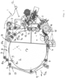
- the baler 1 for forming and/or pressing crops into bales can have a bale forming chamber 2 with a variable diameter, which can be essentially cylindrically contoured.
- the bale forming chamber can be fed with crops or pressed crops via a feed channel 11, whereby the feed channel 11 can be provided in a manner known per se with a conveyor rotor 16 and optionally a cutting device 15.
- a receiving device for example in the form of a pickup with a rotating spiked roller, can be provided in a manner known per se for picking up the crops from the ground.
- Fig.1 shows, at the entrance to the bale forming chamber 2 or in the transition area between the aforementioned feed channel 11 and the bale forming chamber 2, several forming and/or pressing rollers and/or starter rollers 5 and 6 are provided, which come into engagement with the material to be pressed entering the bale forming chamber 2.
- the bale forming chamber 2 comprises further deflection rollers distributed over the circumference of the bale forming chamber 2, over which deflection rollers 4 rotate several belt elements 3 aligned parallel to one another, the orbit of which clings to the bale being formed and, together with it, increases in diameter.
- At least one belt tensioner 7 is assigned to the belt elements 3 circulating around the deflection rollers 4, whereby, as Fig.1 shows, several belt tensioners 7 and 8 can also be provided in order to tension the belt elements 3 and to be able to adapt the orbit or its diameter to the bale which gradually becomes larger during the bale forming process.
- a belt tensioner 7 can be provided on the side of the bale forming chamber 2 on which the inlet of the bale forming chamber 2 and/or the aforementioned starter rollers 5 and 6 are arranged.
- a further belt tensioner 8 can be arranged on a section of the bale forming chamber 2 opposite the inlet of the bale forming chamber 2, for example on an upper side and/or a rear side of the bale forming chamber 2.
- the belt tensioners 7 and 8 can each have one or more deflection rollers 7a and 8a, respectively, which can each be mounted on a swivel arm 7b and 8b or can be adjusted in another way, wherein the mobility of the belt tensioners 7 and 8 is advantageously such that the belt tensioners 7 and 8 can be moved transversely to the orbit of the belt elements 3 inwards into the bale forming chamber 2.
- the arrows 7c and 8c illustrate the adjustment direction and/or pre-tensioning direction of the belt tensioners 7 and 8 respectively.
- the bale forming chamber 2 comprises an unloading door 9, which can advantageously be arranged in a sector of the bale forming chamber 2 facing away from the inlet of the bale forming chamber 2 and/or the starter rollers 5 and 6. If the inlet of the bale forming chamber 2 is provided on the bow side, the unloading door 9 can be arranged on the rear side.
- the unloading door 9 mentioned can basically be mounted in different ways.
- the unloading door 9 can advantageously be pivoted open like a flap about a horizontal door pivot axis 10, whereby the door pivot axis 10 mentioned can be provided on an upper section of the unloading door 9 so that the unloading door 9 can be pivoted upwards.
- the door pivot axis 10 can be provided in the area of one of the deflection rollers 4.
- the arrow 9a shows the possible direction of movement or opening direction of the unloading door 9.
- the unloading door 9 and the belt tensioners 7 and 8 are controlled by an unloading control device 12, whereby the unloading control device 12 can control actuators 13 and 14 for adjusting the belt tensioners 7 and 8 and/or an actuator 17 for adjusting the unloading door 9 in order to control their movements.
- the aforementioned actuators 17 can be hydraulic actuators, for example in the form of hydraulic cylinders, electric rotary motors, spindle drives or the like, whereby the unloading control device 12 can be designed as an electronic control for example, comprising a processor and a program memory.
- the belt tensioner 7 When unloading a bale, the belt tensioner 7 can be moved inwards by opening the unloading door 9 and pressed against the bale in order to push the bale towards the resulting unloading opening. How Fig.1 shows, the movement of the belt tensioner 7 is towards the resulting discharge opening.
- the belt tensioner 7 when unloading a bale, the belt elements 3 remain tensioned. If necessary, the additional belt tensioner 8 can be used for adjustment, i.e. the belt tensioner 8 can be moved additionally so that the desired belt tension is maintained.
- the unloading door 9 is advantageously controlled in such a way that the unloading door 9 remains in contact with the bale moving towards the unloading opening, in particular the said bale pushes the unloading door further and further open with slight resistance until the bale can finally fall out of the unloading opening.
Landscapes
- Life Sciences & Earth Sciences (AREA)
- Environmental Sciences (AREA)
- Storage Of Harvested Produce (AREA)
Claims (9)
- Presse à balles avec une chambre à balles (2) en partie variable ou totalement variable, dans laquelle des produits de récolte de type paille et/ou feuille ou des produits à presser similaires peuvent être façonnés et/ou pressés en balles, dans laquelle la chambre de façonnage de balles (2) présente au moins un élément de courroie (3) circulant autour de poulies de renvoi (4), auquel au moins un tendeur de courroie (7, 8) pouvant être ajusté est associé, dans laquelle la chambre de façonnage de balles (2) présente une porte de déchargement (9) pouvant être montée, et dans laquelle un dispositif de commande de déchargement (12) est prévu pour commander la porte de déchargement (9) et/ou les poulies de renvoi (4) et/ou le tendeur de courroie (7, 8) lors du déchargement d'une balle, caractérisée en ce que le dispositif de commande de déchargement (12) est réalisé pour pousser lors du déchargement le tendeur de courroie (12) contre la balle moyennant ouverture de la porte de déchargement (9) et pour prévoir un déplacement de montée de la porte de déchargement (9), dont le profil de déplacement et/ou le profil de vitesse sont adaptés au mouvement de réglage du tendeur de courroie (7), et ainsi pour pousser la balle par le tendeur de courroie (7) hors de la chambre de façonnage de balles (2) alors que l'élément de courroie (3) reste tendu.
- Presse à balles selon la revendication précédente, dans laquelle le dispositif de déchargement (12) est réalisé pour maintenir, lors du déchargement d'une balle, la porte de déchargement (9) en contact avec la balle et/ou pour la pousser contre la balle.
- Presse à balles selon la revendication précédente, dans laquelle le dispositif de commande de déchargement (12) est réalisé de telle manière que la porte de déchargement (9) est ouverte en poussant lors du déchargement d'une balle par pression par la balle et la porte de déchargement (9) agit contre la balle avec une force contrecarrant l'ouverture en poussant.
- Presse à balles selon la revendication précédente, dans laquelle le dispositif de commande de déchargement (12) commute dans une position flottante lors du déchargement un actionneur de réglage (17) associé à la porte de déchargement (9) et/ou le soumet à l'action d'un blocage de mouvement prédéfini, en particulier d'une contrainte exercée par une force de précontrainte ou par une pression de précontrainte ou par une soupape de limitation d'écoulement.
- Presse à balles selon l'une quelconque des revendications précédentes, dans laquelle le tendeur de courroie (7) soutenant le déchargement de la balle peut être déplacé dans une direction (7c), qui va en direction d'une ouverture de déchargement dégagée par la porte de déchargement (9) ou présente au moins une composante principale allant en direction de ladite ouverture de déchargement.
- Presse à balles selon l'une quelconque des revendications précédentes, dans laquelle le tendeur de courroie (7) soutenant le déchargement de la balle est disposé sur un côté, faisant face à la porte de déchargement (9), de la chambre de façonnage de balles (2).
- Presse à balles selon l'une quelconque des revendications précédentes, dans laquelle le tendeur de courroie (7) soutenant le déchargement de la balle est disposé à proximité de cylindres de démarrage (5, 6), lesquels cylindres de démarrage (5, 6) sont disposés dans une zone d'entrée ou une zone d'admission de la chambre de façonnage de balles (2).
- Presse à balles selon l'une quelconque des revendications précédentes, dans laquelle le tendeur de courroie (7) soutenant le déchargement de la balle peut être déplacé dans le centre de la chambre de façonnage de balles (2) de manière transversale par rapport à la trajectoire circulaire de l'élément de courroie (3).
- Presse à balles selon l'une quelconque des revendications précédentes, dans laquelle au moins un autre tendeur de courroie (8) est prévu et le dispositif de commande de déchargement (12) est réalisé pour commander ultérieurement l'autre tendeur de courroie (8) lors du déchargement d'une balle de telle manière qu'une tension de courroie prédéfinie est maintenue.
Applications Claiming Priority (1)
| Application Number | Priority Date | Filing Date | Title |
|---|---|---|---|
| DE102016001588.8A DE102016001588A1 (de) | 2016-02-11 | 2016-02-11 | Ballenpresse |
Publications (3)
| Publication Number | Publication Date |
|---|---|
| EP3205204A1 EP3205204A1 (fr) | 2017-08-16 |
| EP3205204B1 EP3205204B1 (fr) | 2020-09-02 |
| EP3205204B2 true EP3205204B2 (fr) | 2024-04-17 |
Family
ID=57995105
Family Applications (1)
| Application Number | Title | Priority Date | Filing Date |
|---|---|---|---|
| EP17155164.1A Active EP3205204B2 (fr) | 2016-02-11 | 2017-02-08 | Presse à balles |
Country Status (2)
| Country | Link |
|---|---|
| EP (1) | EP3205204B2 (fr) |
| DE (1) | DE102016001588A1 (fr) |
Citations (4)
| Publication number | Priority date | Publication date | Assignee | Title |
|---|---|---|---|---|
| EP1588604A1 (fr) † | 2004-04-23 | 2005-10-26 | Deere & Company | Presse à balles rondes |
| DE602004009666T2 (de) † | 2004-04-23 | 2008-08-21 | Deere & Company, Moline | Rundballenpresse |
| DE602004010121T2 (de) † | 2004-09-28 | 2008-09-11 | Deere & Company, Moline | Rundballenpresse |
| US7640852B1 (en) † | 2008-11-21 | 2010-01-05 | Deere & Company | Round baler belt-tensioning cylinder arrangement also used for bale ejection |
Family Cites Families (11)
| Publication number | Priority date | Publication date | Assignee | Title |
|---|---|---|---|---|
| CA1072812A (fr) * | 1974-09-19 | 1980-03-04 | Carmen S. Phillips | Presse-lieuse a courroie pour balles cylindriques |
| US4258619A (en) | 1979-06-28 | 1981-03-31 | Hesston Corporation | Rotary baler having bale-ejecting apparatus |
| EP0339730B1 (fr) * | 1988-04-27 | 1993-04-21 | New Holland Belgium N.V. | Presse à balles rondes avec chambre variable et ensemble presseur |
| DE29713514U1 (de) * | 1997-07-29 | 1997-10-02 | Greenland Geldrop B.V., Geldrop | Rundballenpresse |
| DE10303201C5 (de) | 2003-01-28 | 2015-03-12 | Lely Vermeer Maschinenfabrik GmbH | Rundballenpresse für landwirtschaftliche Halmgüter |
| US7140294B1 (en) | 2006-04-07 | 2006-11-28 | Deere & Company | Round baler bale ejecting arrangement |
| DE102006038299A1 (de) | 2006-08-16 | 2008-02-28 | Deere & Company, Moline | Rundballenpresse |
| DE102011010251A1 (de) | 2011-02-03 | 2012-08-09 | Alois Pöttinger Maschinenfabrik Gmbh | Ballenpresse |
| DE202012006898U1 (de) | 2012-07-17 | 2013-10-18 | Alois Pöttinger Maschinenfabrik Ges.m.b.H. | Ballenpresse |
| US9241443B2 (en) | 2014-03-13 | 2016-01-26 | Deere & Company | Gate position control of round bale discharge |
| NL2012638B1 (en) | 2014-04-16 | 2016-07-15 | Forage Innovations Bv | Apparatus and method for forming a round bale with a tensioned pressing means. |
-
2016
- 2016-02-11 DE DE102016001588.8A patent/DE102016001588A1/de not_active Withdrawn
-
2017
- 2017-02-08 EP EP17155164.1A patent/EP3205204B2/fr active Active
Patent Citations (4)
| Publication number | Priority date | Publication date | Assignee | Title |
|---|---|---|---|---|
| EP1588604A1 (fr) † | 2004-04-23 | 2005-10-26 | Deere & Company | Presse à balles rondes |
| DE602004009666T2 (de) † | 2004-04-23 | 2008-08-21 | Deere & Company, Moline | Rundballenpresse |
| DE602004010121T2 (de) † | 2004-09-28 | 2008-09-11 | Deere & Company, Moline | Rundballenpresse |
| US7640852B1 (en) † | 2008-11-21 | 2010-01-05 | Deere & Company | Round baler belt-tensioning cylinder arrangement also used for bale ejection |
Also Published As
| Publication number | Publication date |
|---|---|
| DE102016001588A1 (de) | 2017-08-17 |
| EP3205204A1 (fr) | 2017-08-16 |
| EP3205204B1 (fr) | 2020-09-02 |
Similar Documents
| Publication | Publication Date | Title |
|---|---|---|
| DE60131524T2 (de) | Rundballenpresse | |
| EP0931449B1 (fr) | Presse avec dispositif d'enveloppage | |
| EP2484197B1 (fr) | Presse à balles rondes dotée de guidages latéraux pour courroies de presse | |
| DE10063122A1 (de) | Rundballenpresse | |
| EP4108069B1 (fr) | Presse à balles rondes | |
| EP1769673A1 (fr) | Presse à balles rondes | |
| EP1969918B1 (fr) | Presse à ballots ronds et procédé de modification de la friction sur ses parois latérales | |
| EP3266299B1 (fr) | Presse à balles | |
| EP1932419B1 (fr) | Presse agricole | |
| EP0102530A1 (fr) | Méthode pour enlever les surcharges dûes aux amassements de récolte lors de l'enroulement de balles rondes | |
| EP0499909A1 (fr) | Presse à balles rondes | |
| EP3721700B1 (fr) | Dispositif d'enroulement de balles pour une presse à balles rondes et presse à balles rondes | |
| EP1726204B1 (fr) | Presse et appareil pour envelopper des balles rondes | |
| EP3459341B1 (fr) | Presse à balles rondes agricole | |
| EP2687083B1 (fr) | Presse à empaqueter | |
| EP3205204B2 (fr) | Presse à balles | |
| DE10063120A1 (de) | Rundballenpresse | |
| EP3106021B1 (fr) | Presse à balles rondes | |
| EP3501261B1 (fr) | Moyen de guidage, presse à balles et procédé | |
| EP0986306A1 (fr) | Procede et dispositif pour former des produits de boulangerie roules | |
| DE4012739C2 (de) | Umhüllungseinrichtung für Rundballen in Ballenpressen | |
| DE60128563T2 (de) | Einwickelsystem für eine Rundballenpresse | |
| DE8802337U1 (de) | Rundballenpresse | |
| EP4074162A1 (fr) | Presse à balles rondes pourvue de rouleau de démarrage et d'élément de déviation pouvant être dévié élastiquement | |
| EP3123857B1 (fr) | Dispositif d'enrubannage de balles, appareil de récupération de cueillette et procédé |
Legal Events
| Date | Code | Title | Description |
|---|---|---|---|
| PUAI | Public reference made under article 153(3) epc to a published international application that has entered the european phase |
Free format text: ORIGINAL CODE: 0009012 |
|
| STAA | Information on the status of an ep patent application or granted ep patent |
Free format text: STATUS: THE APPLICATION HAS BEEN PUBLISHED |
|
| AK | Designated contracting states |
Kind code of ref document: A1 Designated state(s): AL AT BE BG CH CY CZ DE DK EE ES FI FR GB GR HR HU IE IS IT LI LT LU LV MC MK MT NL NO PL PT RO RS SE SI SK SM TR |
|
| AX | Request for extension of the european patent |
Extension state: BA ME |
|
| STAA | Information on the status of an ep patent application or granted ep patent |
Free format text: STATUS: REQUEST FOR EXAMINATION WAS MADE |
|
| 17P | Request for examination filed |
Effective date: 20180207 |
|
| RBV | Designated contracting states (corrected) |
Designated state(s): AL AT BE BG CH CY CZ DE DK EE ES FI FR GB GR HR HU IE IS IT LI LT LU LV MC MK MT NL NO PL PT RO RS SE SI SK SM TR |
|
| GRAP | Despatch of communication of intention to grant a patent |
Free format text: ORIGINAL CODE: EPIDOSNIGR1 |
|
| STAA | Information on the status of an ep patent application or granted ep patent |
Free format text: STATUS: GRANT OF PATENT IS INTENDED |
|
| INTG | Intention to grant announced |
Effective date: 20200507 |
|
| GRAS | Grant fee paid |
Free format text: ORIGINAL CODE: EPIDOSNIGR3 |
|
| GRAA | (expected) grant |
Free format text: ORIGINAL CODE: 0009210 |
|
| STAA | Information on the status of an ep patent application or granted ep patent |
Free format text: STATUS: THE PATENT HAS BEEN GRANTED |
|
| AK | Designated contracting states |
Kind code of ref document: B1 Designated state(s): AL AT BE BG CH CY CZ DE DK EE ES FI FR GB GR HR HU IE IS IT LI LT LU LV MC MK MT NL NO PL PT RO RS SE SI SK SM TR |
|
| REG | Reference to a national code |
Ref country code: GB Ref legal event code: FG4D Free format text: NOT ENGLISH |
|
| REG | Reference to a national code |
Ref country code: AT Ref legal event code: REF Ref document number: 1307717 Country of ref document: AT Kind code of ref document: T Effective date: 20200915 Ref country code: CH Ref legal event code: EP |
|
| REG | Reference to a national code |
Ref country code: DE Ref legal event code: R096 Ref document number: 502017006985 Country of ref document: DE |
|
| REG | Reference to a national code |
Ref country code: IE Ref legal event code: FG4D Free format text: LANGUAGE OF EP DOCUMENT: GERMAN |
|
| REG | Reference to a national code |
Ref country code: NL Ref legal event code: FP |
|
| REG | Reference to a national code |
Ref country code: LT Ref legal event code: MG4D |
|
| PG25 | Lapsed in a contracting state [announced via postgrant information from national office to epo] |
Ref country code: GR Free format text: LAPSE BECAUSE OF FAILURE TO SUBMIT A TRANSLATION OF THE DESCRIPTION OR TO PAY THE FEE WITHIN THE PRESCRIBED TIME-LIMIT Effective date: 20201203 Ref country code: FI Free format text: LAPSE BECAUSE OF FAILURE TO SUBMIT A TRANSLATION OF THE DESCRIPTION OR TO PAY THE FEE WITHIN THE PRESCRIBED TIME-LIMIT Effective date: 20200902 Ref country code: HR Free format text: LAPSE BECAUSE OF FAILURE TO SUBMIT A TRANSLATION OF THE DESCRIPTION OR TO PAY THE FEE WITHIN THE PRESCRIBED TIME-LIMIT Effective date: 20200902 Ref country code: NO Free format text: LAPSE BECAUSE OF FAILURE TO SUBMIT A TRANSLATION OF THE DESCRIPTION OR TO PAY THE FEE WITHIN THE PRESCRIBED TIME-LIMIT Effective date: 20201202 Ref country code: SE Free format text: LAPSE BECAUSE OF FAILURE TO SUBMIT A TRANSLATION OF THE DESCRIPTION OR TO PAY THE FEE WITHIN THE PRESCRIBED TIME-LIMIT Effective date: 20200902 Ref country code: LT Free format text: LAPSE BECAUSE OF FAILURE TO SUBMIT A TRANSLATION OF THE DESCRIPTION OR TO PAY THE FEE WITHIN THE PRESCRIBED TIME-LIMIT Effective date: 20200902 Ref country code: BG Free format text: LAPSE BECAUSE OF FAILURE TO SUBMIT A TRANSLATION OF THE DESCRIPTION OR TO PAY THE FEE WITHIN THE PRESCRIBED TIME-LIMIT Effective date: 20201202 |
|
| PG25 | Lapsed in a contracting state [announced via postgrant information from national office to epo] |
Ref country code: PL Free format text: LAPSE BECAUSE OF FAILURE TO SUBMIT A TRANSLATION OF THE DESCRIPTION OR TO PAY THE FEE WITHIN THE PRESCRIBED TIME-LIMIT Effective date: 20200902 Ref country code: LV Free format text: LAPSE BECAUSE OF FAILURE TO SUBMIT A TRANSLATION OF THE DESCRIPTION OR TO PAY THE FEE WITHIN THE PRESCRIBED TIME-LIMIT Effective date: 20200902 Ref country code: RS Free format text: LAPSE BECAUSE OF FAILURE TO SUBMIT A TRANSLATION OF THE DESCRIPTION OR TO PAY THE FEE WITHIN THE PRESCRIBED TIME-LIMIT Effective date: 20200902 |
|
| PG25 | Lapsed in a contracting state [announced via postgrant information from national office to epo] |
Ref country code: CZ Free format text: LAPSE BECAUSE OF FAILURE TO SUBMIT A TRANSLATION OF THE DESCRIPTION OR TO PAY THE FEE WITHIN THE PRESCRIBED TIME-LIMIT Effective date: 20200902 Ref country code: PT Free format text: LAPSE BECAUSE OF FAILURE TO SUBMIT A TRANSLATION OF THE DESCRIPTION OR TO PAY THE FEE WITHIN THE PRESCRIBED TIME-LIMIT Effective date: 20210104 Ref country code: RO Free format text: LAPSE BECAUSE OF FAILURE TO SUBMIT A TRANSLATION OF THE DESCRIPTION OR TO PAY THE FEE WITHIN THE PRESCRIBED TIME-LIMIT Effective date: 20200902 Ref country code: SM Free format text: LAPSE BECAUSE OF FAILURE TO SUBMIT A TRANSLATION OF THE DESCRIPTION OR TO PAY THE FEE WITHIN THE PRESCRIBED TIME-LIMIT Effective date: 20200902 Ref country code: EE Free format text: LAPSE BECAUSE OF FAILURE TO SUBMIT A TRANSLATION OF THE DESCRIPTION OR TO PAY THE FEE WITHIN THE PRESCRIBED TIME-LIMIT Effective date: 20200902 |
|
| PG25 | Lapsed in a contracting state [announced via postgrant information from national office to epo] |
Ref country code: AL Free format text: LAPSE BECAUSE OF FAILURE TO SUBMIT A TRANSLATION OF THE DESCRIPTION OR TO PAY THE FEE WITHIN THE PRESCRIBED TIME-LIMIT Effective date: 20200902 Ref country code: ES Free format text: LAPSE BECAUSE OF FAILURE TO SUBMIT A TRANSLATION OF THE DESCRIPTION OR TO PAY THE FEE WITHIN THE PRESCRIBED TIME-LIMIT Effective date: 20200902 Ref country code: IS Free format text: LAPSE BECAUSE OF FAILURE TO SUBMIT A TRANSLATION OF THE DESCRIPTION OR TO PAY THE FEE WITHIN THE PRESCRIBED TIME-LIMIT Effective date: 20210102 |
|
| REG | Reference to a national code |
Ref country code: DE Ref legal event code: R026 Ref document number: 502017006985 Country of ref document: DE |
|
| PLBI | Opposition filed |
Free format text: ORIGINAL CODE: 0009260 |
|
| PLAX | Notice of opposition and request to file observation + time limit sent |
Free format text: ORIGINAL CODE: EPIDOSNOBS2 |
|
| PG25 | Lapsed in a contracting state [announced via postgrant information from national office to epo] |
Ref country code: SK Free format text: LAPSE BECAUSE OF FAILURE TO SUBMIT A TRANSLATION OF THE DESCRIPTION OR TO PAY THE FEE WITHIN THE PRESCRIBED TIME-LIMIT Effective date: 20200902 |
|
| 26 | Opposition filed |
Opponent name: MASCHINENFABRIK BERNARD KRONE GMBH & CO. KG Effective date: 20210601 |
|
| PG25 | Lapsed in a contracting state [announced via postgrant information from national office to epo] |
Ref country code: SI Free format text: LAPSE BECAUSE OF FAILURE TO SUBMIT A TRANSLATION OF THE DESCRIPTION OR TO PAY THE FEE WITHIN THE PRESCRIBED TIME-LIMIT Effective date: 20200902 Ref country code: DK Free format text: LAPSE BECAUSE OF FAILURE TO SUBMIT A TRANSLATION OF THE DESCRIPTION OR TO PAY THE FEE WITHIN THE PRESCRIBED TIME-LIMIT Effective date: 20200902 |
|
| PG25 | Lapsed in a contracting state [announced via postgrant information from national office to epo] |
Ref country code: MC Free format text: LAPSE BECAUSE OF FAILURE TO SUBMIT A TRANSLATION OF THE DESCRIPTION OR TO PAY THE FEE WITHIN THE PRESCRIBED TIME-LIMIT Effective date: 20200902 |
|
| GBPC | Gb: european patent ceased through non-payment of renewal fee |
Effective date: 20210208 |
|
| REG | Reference to a national code |
Ref country code: BE Ref legal event code: MM Effective date: 20210228 |
|
| PG25 | Lapsed in a contracting state [announced via postgrant information from national office to epo] |
Ref country code: CH Free format text: LAPSE BECAUSE OF NON-PAYMENT OF DUE FEES Effective date: 20210228 Ref country code: IT Free format text: LAPSE BECAUSE OF FAILURE TO SUBMIT A TRANSLATION OF THE DESCRIPTION OR TO PAY THE FEE WITHIN THE PRESCRIBED TIME-LIMIT Effective date: 20200902 Ref country code: LU Free format text: LAPSE BECAUSE OF NON-PAYMENT OF DUE FEES Effective date: 20210208 Ref country code: LI Free format text: LAPSE BECAUSE OF NON-PAYMENT OF DUE FEES Effective date: 20210228 |
|
| PLBB | Reply of patent proprietor to notice(s) of opposition received |
Free format text: ORIGINAL CODE: EPIDOSNOBS3 |
|
| PG25 | Lapsed in a contracting state [announced via postgrant information from national office to epo] |
Ref country code: GB Free format text: LAPSE BECAUSE OF NON-PAYMENT OF DUE FEES Effective date: 20210208 |
|
| PG25 | Lapsed in a contracting state [announced via postgrant information from national office to epo] |
Ref country code: BE Free format text: LAPSE BECAUSE OF NON-PAYMENT OF DUE FEES Effective date: 20210228 |
|
| PLAB | Opposition data, opponent's data or that of the opponent's representative modified |
Free format text: ORIGINAL CODE: 0009299OPPO |
|
| R26 | Opposition filed (corrected) |
Opponent name: MASCHINENFABRIK BERNARD KRONE GMBH & CO. KG Effective date: 20210601 |
|
| REG | Reference to a national code |
Ref country code: AT Ref legal event code: MM01 Ref document number: 1307717 Country of ref document: AT Kind code of ref document: T Effective date: 20220208 |
|
| PG25 | Lapsed in a contracting state [announced via postgrant information from national office to epo] |
Ref country code: AT Free format text: LAPSE BECAUSE OF NON-PAYMENT OF DUE FEES Effective date: 20220208 |
|
| PG25 | Lapsed in a contracting state [announced via postgrant information from national office to epo] |
Ref country code: HU Free format text: LAPSE BECAUSE OF FAILURE TO SUBMIT A TRANSLATION OF THE DESCRIPTION OR TO PAY THE FEE WITHIN THE PRESCRIBED TIME-LIMIT; INVALID AB INITIO Effective date: 20170208 |
|
| PG25 | Lapsed in a contracting state [announced via postgrant information from national office to epo] |
Ref country code: CY Free format text: LAPSE BECAUSE OF FAILURE TO SUBMIT A TRANSLATION OF THE DESCRIPTION OR TO PAY THE FEE WITHIN THE PRESCRIBED TIME-LIMIT Effective date: 20200902 |
|
| PUAH | Patent maintained in amended form |
Free format text: ORIGINAL CODE: 0009272 |
|
| STAA | Information on the status of an ep patent application or granted ep patent |
Free format text: STATUS: PATENT MAINTAINED AS AMENDED |
|
| 27A | Patent maintained in amended form |
Effective date: 20240417 |
|
| AK | Designated contracting states |
Kind code of ref document: B2 Designated state(s): AL AT BE BG CH CY CZ DE DK EE ES FI FR GB GR HR HU IE IS IT LI LT LU LV MC MK MT NL NO PL PT RO RS SE SI SK SM TR |
|
| REG | Reference to a national code |
Ref country code: DE Ref legal event code: R102 Ref document number: 502017006985 Country of ref document: DE |
|
| PG25 | Lapsed in a contracting state [announced via postgrant information from national office to epo] |
Ref country code: MK Free format text: LAPSE BECAUSE OF FAILURE TO SUBMIT A TRANSLATION OF THE DESCRIPTION OR TO PAY THE FEE WITHIN THE PRESCRIBED TIME-LIMIT Effective date: 20200902 |
|
| REG | Reference to a national code |
Ref country code: NL Ref legal event code: FP |
|
| PG25 | Lapsed in a contracting state [announced via postgrant information from national office to epo] |
Ref country code: MT Free format text: LAPSE BECAUSE OF FAILURE TO SUBMIT A TRANSLATION OF THE DESCRIPTION OR TO PAY THE FEE WITHIN THE PRESCRIBED TIME-LIMIT Effective date: 20200902 |
|
| PG25 | Lapsed in a contracting state [announced via postgrant information from national office to epo] |
Ref country code: TR Free format text: LAPSE BECAUSE OF FAILURE TO SUBMIT A TRANSLATION OF THE DESCRIPTION OR TO PAY THE FEE WITHIN THE PRESCRIBED TIME-LIMIT Effective date: 20200902 |
|
| PGFP | Annual fee paid to national office [announced via postgrant information from national office to epo] |
Ref country code: NL Payment date: 20260219 Year of fee payment: 10 |
|
| PGFP | Annual fee paid to national office [announced via postgrant information from national office to epo] |
Ref country code: DE Payment date: 20260218 Year of fee payment: 10 Ref country code: IE Payment date: 20260225 Year of fee payment: 10 |
|
| PGFP | Annual fee paid to national office [announced via postgrant information from national office to epo] |
Ref country code: FR Payment date: 20260225 Year of fee payment: 10 |