EP3205227A1 - Stock für sportaktivitäten, insbesondere zum wandern und dergleichen - Google Patents
Stock für sportaktivitäten, insbesondere zum wandern und dergleichen Download PDFInfo
- Publication number
- EP3205227A1 EP3205227A1 EP17155475.1A EP17155475A EP3205227A1 EP 3205227 A1 EP3205227 A1 EP 3205227A1 EP 17155475 A EP17155475 A EP 17155475A EP 3205227 A1 EP3205227 A1 EP 3205227A1
- Authority
- EP
- European Patent Office
- Prior art keywords
- rod
- shaped body
- pole
- support structure
- sports
- Prior art date
- Legal status (The legal status is an assumption and is not a legal conclusion. Google has not performed a legal analysis and makes no representation as to the accuracy of the status listed.)
- Withdrawn
Links
- 230000000694 effects Effects 0.000 title description 3
- 230000000284 resting effect Effects 0.000 claims abstract description 5
- 210000000245 forearm Anatomy 0.000 claims description 8
- 210000001364 upper extremity Anatomy 0.000 description 9
- 230000008878 coupling Effects 0.000 description 4
- 238000010168 coupling process Methods 0.000 description 4
- 238000005859 coupling reaction Methods 0.000 description 4
- 230000037396 body weight Effects 0.000 description 2
- 210000003414 extremity Anatomy 0.000 description 2
- 210000003205 muscle Anatomy 0.000 description 2
- 239000006096 absorbing agent Substances 0.000 description 1
- 238000005273 aeration Methods 0.000 description 1
- 238000010276 construction Methods 0.000 description 1
- 229930183489 erectone Natural products 0.000 description 1
- 230000005484 gravity Effects 0.000 description 1
- 238000003780 insertion Methods 0.000 description 1
- 230000037431 insertion Effects 0.000 description 1
- 239000000463 material Substances 0.000 description 1
- 238000013021 overheating Methods 0.000 description 1
- 230000037081 physical activity Effects 0.000 description 1
- 230000035939 shock Effects 0.000 description 1
- 210000000707 wrist Anatomy 0.000 description 1
Images

Classifications
-
- A—HUMAN NECESSITIES
- A45—HAND OR TRAVELLING ARTICLES
- A45B—WALKING STICKS; UMBRELLAS; LADIES' OR LIKE FANS
- A45B9/00—Details
- A45B9/02—Handles or heads
-
- A—HUMAN NECESSITIES
- A63—SPORTS; GAMES; AMUSEMENTS
- A63C—SKATES; SKIS; ROLLER SKATES; DESIGN OR LAYOUT OF COURTS, RINKS OR THE LIKE
- A63C11/00—Accessories for skiing or snowboarding
- A63C11/22—Ski-sticks
- A63C11/222—Ski-stick handles or hand-straps
-
- A—HUMAN NECESSITIES
- A45—HAND OR TRAVELLING ARTICLES
- A45B—WALKING STICKS; UMBRELLAS; LADIES' OR LIKE FANS
- A45B7/00—Other sticks, e.g. of cranked shape
- A45B7/005—Other sticks, e.g. of cranked shape crank-shaped
-
- A—HUMAN NECESSITIES
- A45—HAND OR TRAVELLING ARTICLES
- A45B—WALKING STICKS; UMBRELLAS; LADIES' OR LIKE FANS
- A45B9/00—Details
- A45B2009/002—Accessories
Definitions
- the present invention relates to a pole for sports activities such as trekking, hiking or other similar sports.
- poles are currently used which are generally of the type with telescopic rod, a ferrule being mounted at a first end of which is forced against the ground and a gripping knob for the user being fixedly mounted at the opposite end.
- Poles for sports constitute a support for the body, in fact forming an extension of the upper limbs which are thereby used as assistants of the movement. In brief, their use facilitates the balance, the weight distribution on all four limbs and the symmetry of the walk.
- the Applicant has found that, however, the percentage of weight relieved on the upper limbs through the poles of the known type generally does not exceed 26% of the body weight and of any loads on the shoulders.
- the Applicant has further identified a connection between the reduced weight percentage relieved and the substantially erect body position imposed by the use of poles for sports of the known type, also in the presence of inclined ground.
- the Applicant has, in fact, observed that, in the case of inclined ground, the natural position one tends to assume in the absence of poles greatly differs from the erect one. Specifically, it is characterized by having the centre of gravity displaced in such a way as to compensate the inclination of the ground up to get to have, in the event of significant inclinations, also the upper limbs resting on the ground.
- the Applicant has therefore identified a need to implement a pole for sports which allows relieving more weight on the upper limbs with respect to the poles of the known type.
- the Applicant has felt the need to implement a pole for sports which can be adapted to the specific ground slope offering a more optimised support to the user.
- the problem underlying the present invention is therefore to provide a pole for sports that is functionally and structurally designed to enable the overcoming of the drawbacks mentioned with reference to the discussed prior art.
- an object of the present invention is therefore to devise a pole for sports able to adapt to the slope of the ground on which it is used in order to offer a more secure support for the upper limbs to the user, through which a good part of the weight is relieved.
- the invention relates to a pole for sports comprising a rod-shaped body having a development axis, a ferrule, for resting on the ground, being mounted at a first end of the rod-shaped body characterised in that, at a second end of the rod-shaped body, opposite to the first end, a support structure having a main development axis is mounted, the support structure being mounted according to an inclination which is adjustable with respect to the rod-shaped body and comprising a gripping portion developing transversally with respect to the main development axis of the support structure.
- the applicant has identified that through an adjustable inclination of the gripping portion of the pole and in any case substantially coinciding with the axis of the rod-shaped body of the pole, it is possible to optimise the weight relieved on the arms.
- the Applicant has observed that through the greater involvement of the upper limbs and the relative muscles, it is possible to produce overall less fatigue, making the walk more pleasant and often more productive in terms of distance travelled and/or travelling speed.
- the present invention may have at least one of the following preferred features; the latter may in particular be combined with each other as desired to meet specific application requirements.
- the gripping portion of the support structure develops substantially orthogonal to the main development axis of the support structure.
- the gripping portion of the support structure is connected, at a first end part thereof, to the second end of the rod-shaped body by interposing a flexible portion.
- the flexible portion comprises a curved configuration.
- the flexible portion allows absorbing a higher thrust resulting from the larger weight relieved. A reduction of the stresses suffered at the wrists is thus obtained.
- the support structure comprises an armrest for engaging with a user's forearm, connected to a second end of the gripping portion.
- the arm has at least a curved surface which defines a seat for at least partially receiving a forearm.
- the curved surface comprises at least one aeration window.
- the presence of the armrest allows engaging also the forearm in the movement up to make it substantially integral with the pole.
- the pole becomes a limb extension, allowing it to interact with the ground as if in direct support.
- means for locking the relative position between the support structure and the rod-shaped body are interposed.
- the locking means comprising a pair of discs arranged side by side, provided with inner faces shaped in a matching manner so as to prevent a relative rotation between the two discs when arranged side-by side, a first disc being constrained to the support structure and a second disc being constrained to the rod-shaped body.
- the first disc is fixedly connected an end of the support structure close to the gripping portion.
- the second disc is fixedly connected to constraining means for the rod-shaped body.
- the two disks are maintained in mutual engagement by means of clamping means, such as a tightening wheel which engages threadedly with both discs, an axial lever of the type for quick clamping or other equivalent clamping means.
- clamping means such as a tightening wheel which engages threadedly with both discs, an axial lever of the type for quick clamping or other equivalent clamping means.
- protrusions are provided shaped like rays in such a way as to define a plurality of angular positions of mutual coupling between the two discs.
- the angular positions enabled by the mutual coupling between the two discs vary between a position of the support structure with the main development axis coinciding with the development axis of the rod-shaped body and a position of the support structure with the main development axis substantially parallel and next to the development axis of the rod-shaped body.
- the means for constraining to the rod-shaped body are of the removable type and a gripping knob is coaxially mounted at a second end of the rod-shaped body, opposite to the first one.
- the releasable constraining means are housed in the cavity of the rod-shaped body at the second end to which the gripping knob is mounted.
- the constraining means comprise a spring clip shaped so as to engage a head of a pin integral with the second disc.
- the gripping knob comprises superiorly an opening suitable for inserting the pin.
- the spring clip can be operated to be opened by a pair of buttons protruding from the rod-shaped body.
- the constraining means to the rod-shaped body are of the fixed type.
- the fixed constraining means comprise a threaded pin which can be screwed in the inner cavity of the rod-shaped body, at the second end of said rod-shaped body.
- the rod-shaped body is of the telescopic type or of the type comprising a plurality of joints to be able to take a folded compact configuration.
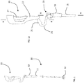
- a first embodiment of a pole 10 for sports comprising a rod-shaped body 11 of the telescopic type, having a development axis A.
- a ferrule 12 for resting on the ground is mounted at a first end of the rod-shaped body 11 and at a second end, opposite to the first end, a gripping knob 13 for user 100 is mounted.
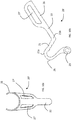
- a support structure 20 is advantageously mounted at the second end, having a main development axis B, shown enlarged in figure 1a .
- the support structure 20 is constrained to the rod-shaped body 11 according to an adjustable inclination and comprises a gripping portion 21 which extends substantially orthogonally with respect to the main development axis B of the support structure 20.
- means 23 for locking the relative position between the support structure 20 and the rod-shaped body 11 are provided.
- such locking means 23 comprise two discs 23a, 23b provided with inner faces with protrusions 24a, 24b shaped in a matching manner so as to prevent a relative rotation between the two faces.
- protrusions 24a, 24b provided on the inner faces are shaped like rays in such a way as to define a plurality of angular positions of mutual coupling between the two discs 23a, 23b.
- the angular positions enabled by the mutual coupling between the two discs 23a, 23b vary between a position of the support structure 20 in extension of the rod-shaped body 11 and a position of the support structure 20 next to the rod-shaped body 11.
- the support structure 20 is carried to such a second flanked position, illustrated in figure 4 , in order to reduce the overall dimensions of pole 10 when it has to be stored.
- Figures 2 and 3 show, by way of example, two further possible inclinations at which the support structure 20 can be constrained depending on the specific inclination of the ground on which pole 10 must be used.
- the two discs 23a, 23b are kept in mutual engagement by a tightening wheel 26 which engages in screwing with both discs 23a, 23b.
- a first disc 23a is fixedly constrained to the support structure 20, particularly at one end of the same next to the gripping portion 21.
- a second disc 23b is fixedly connected to constraining means 30 for the rod-shaped body 11.
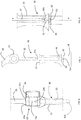
- a first embodiment of the constraining means 30 is shown in figures 7 and 8 .
- the constraining means 30 shown in figures 7 and 8 are releasable and comprise a spring clip 31 shaped so as to engage with head 32a of a pin 32 integral with the second disc 23b.
- the spring clip 31 can be operated to be opened by a pair of buttons 33 placed in such a way as to protrude from the rod-shaped body 11. The pressure of the pair of buttons 33 counteracts the action of spring 31a, allowing the spring clip 31 to spread apart and thereby release the engagement with head 32a of pin 32.
- the releasable constraining means 30 are housed in the cavity of the rod-shaped body 11 at the second end to which the gripping knob 13 is mounted.
- the gripping knob 13 superiorly comprises an opening which allows the insertion of pin 32 inside such a knob 13.
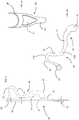
- a second embodiment of pole 10' for sports shown in figures 9, 9a and 9b , comprises fixed constraining means 30' , without gripping knobs.
- the constraining means 30' of fixed type shown in figures 9a and 9b comprise a threaded pin 32' screwable in the inner cavity of the rod-shaped body 11, at the second end thereof.
- the gripping portion 21 of the support structure 20 is connected, at a first end part 21a thereof, to the first disc 23a by interposing a flexible curved portion 25 acting as a shock absorber.
- the support structure 20 further comprises an armrest 22 for engaging with a user's forearm 101, integrally connected to a second end 21b of the gripping portion 21.
- Armrest 22 has at least one curved surface 28 which defines an at least partial housing for forearm 101.
- a curved surface 28 comprises at least one window 27 which allows overheating of the body part 101 in support on the same.
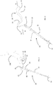
- Figures 5a and 5b and 10a and 10b show two possible embodiments of support structures 20, 20' used in pole 10, 10' for sports according to the present invention which differ substantially in the shape and number of windows 27, 27'.
- pole 10, 10' for sports according to the present invention is as follows.
- the locking means 23 are initially set in such a way as to impart a specific relative inclination to the support structure 20 with respect to the rod-shaped body 11.
- the most suitable length of the rod-shaped body 11 of telescopic type is also set.
- Inclination and length are selected according to the specific slope to be travelled on, allowing the user to take the most suited position.
- the user takes a posture in which the arm is substantially in line with the main axis A of the rod-shaped body 11, or at most inclined by a reduced angle with respect to the same.
- the user can relieve more body weight through the upper limbs, compared to traditional poles that impose an angle substantially equal to 90° between the forearm and the main axis A of the rod-shaped body 11.
- pole 10 may be used in the traditional manner, by operating buttons 33 protruding from the rod-shaped body 11 and removing pin 32 from the engagement with the spring clip 31. Once the support structure 20 has been removed, pole 10 can be used in a known manner, holding the dedicated gripping knob 13.
Landscapes
- Steering Devices For Bicycles And Motorcycles (AREA)
Applications Claiming Priority (1)
| Application Number | Priority Date | Filing Date | Title |
|---|---|---|---|
| ITUB2016A000687A ITUB20160687A1 (it) | 2016-02-11 | 2016-02-11 | Bastoncino per attivita' sportive, in particolare per trekking e simili |
Publications (1)
| Publication Number | Publication Date |
|---|---|
| EP3205227A1 true EP3205227A1 (de) | 2017-08-16 |
Family
ID=55969302
Family Applications (1)
| Application Number | Title | Priority Date | Filing Date |
|---|---|---|---|
| EP17155475.1A Withdrawn EP3205227A1 (de) | 2016-02-11 | 2017-02-09 | Stock für sportaktivitäten, insbesondere zum wandern und dergleichen |
Country Status (2)
| Country | Link |
|---|---|
| EP (1) | EP3205227A1 (de) |
| IT (1) | ITUB20160687A1 (de) |
Cited By (3)
| Publication number | Priority date | Publication date | Assignee | Title |
|---|---|---|---|---|
| US10537489B1 (en) * | 2018-08-08 | 2020-01-21 | Hyundai Motor Company | Crutch having joint structure |
| US10722010B2 (en) | 2018-07-30 | 2020-07-28 | Douglas J. D'Jay | Systems and methods for adjustable length weighted trekking poles |
| EP3908379A1 (de) | 2019-01-10 | 2021-11-17 | Creaforce Oy | Stock für nordic walking/laufen/training |
Citations (8)
| Publication number | Priority date | Publication date | Assignee | Title |
|---|---|---|---|---|
| US2408604A (en) * | 1944-11-22 | 1946-10-01 | Al R Brooks | Crutch |
| FR2517551A2 (fr) * | 1981-07-08 | 1983-06-10 | Kerma | Baton de ski |
| US4597589A (en) * | 1984-03-16 | 1986-07-01 | Fujii Ray K | Pivoted grip ski pole |
| WO1990011031A1 (en) * | 1989-03-23 | 1990-10-04 | Rhodes Heather A G | Walking aid |
| US5996602A (en) * | 1996-07-29 | 1999-12-07 | Mobility Devices, Inc. | Hiking pole |
| WO2005041844A1 (ja) * | 2003-11-04 | 2005-05-12 | Hirokazu Inoue | 前腕保持具が可傾の杖、および杖に着脱できる前腕保持具の可傾連結装置 |
| DE102010053107A1 (de) * | 2010-12-01 | 2012-06-06 | Leonhard Brader | Verformbarer Stockgriff |
| WO2013168144A2 (en) * | 2012-05-11 | 2013-11-14 | Brignone Renato | Adjustable crutch |
-
2016
- 2016-02-11 IT ITUB2016A000687A patent/ITUB20160687A1/it unknown
-
2017
- 2017-02-09 EP EP17155475.1A patent/EP3205227A1/de not_active Withdrawn
Patent Citations (8)
| Publication number | Priority date | Publication date | Assignee | Title |
|---|---|---|---|---|
| US2408604A (en) * | 1944-11-22 | 1946-10-01 | Al R Brooks | Crutch |
| FR2517551A2 (fr) * | 1981-07-08 | 1983-06-10 | Kerma | Baton de ski |
| US4597589A (en) * | 1984-03-16 | 1986-07-01 | Fujii Ray K | Pivoted grip ski pole |
| WO1990011031A1 (en) * | 1989-03-23 | 1990-10-04 | Rhodes Heather A G | Walking aid |
| US5996602A (en) * | 1996-07-29 | 1999-12-07 | Mobility Devices, Inc. | Hiking pole |
| WO2005041844A1 (ja) * | 2003-11-04 | 2005-05-12 | Hirokazu Inoue | 前腕保持具が可傾の杖、および杖に着脱できる前腕保持具の可傾連結装置 |
| DE102010053107A1 (de) * | 2010-12-01 | 2012-06-06 | Leonhard Brader | Verformbarer Stockgriff |
| WO2013168144A2 (en) * | 2012-05-11 | 2013-11-14 | Brignone Renato | Adjustable crutch |
Cited By (5)
| Publication number | Priority date | Publication date | Assignee | Title |
|---|---|---|---|---|
| US10722010B2 (en) | 2018-07-30 | 2020-07-28 | Douglas J. D'Jay | Systems and methods for adjustable length weighted trekking poles |
| US10537489B1 (en) * | 2018-08-08 | 2020-01-21 | Hyundai Motor Company | Crutch having joint structure |
| EP3908379A1 (de) | 2019-01-10 | 2021-11-17 | Creaforce Oy | Stock für nordic walking/laufen/training |
| EP3908379A4 (de) * | 2019-01-10 | 2022-10-05 | Creaforce Oy | Stock für nordic walking/laufen/training |
| US11918092B2 (en) | 2019-01-10 | 2024-03-05 | Creaforce Oy | Nordic walking/running/exercise pole |
Also Published As
| Publication number | Publication date |
|---|---|
| ITUB20160687A1 (it) | 2017-08-11 |
Similar Documents
| Publication | Publication Date | Title |
|---|---|---|
| US8474470B2 (en) | Crutch | |
| US5495867A (en) | Dual handled cane | |
| US6085766A (en) | Geary convertible crutch system | |
| US8082936B2 (en) | Walking cane | |
| US3304946A (en) | Crutch | |
| US5996602A (en) | Hiking pole | |
| US7270138B2 (en) | Joint mechanism | |
| US6695754B1 (en) | Exercise device for supporting at least one ankle during a physical exercise | |
| JP2001502932A (ja) | スキーストック、ハイキングステッキなどの杖 | |
| CN208910879U (zh) | 一种辅助行走的骨科助力拐杖 | |
| JP2019071982A (ja) | 杖先及び杖 | |
| US20060124163A1 (en) | Crutch | |
| US7451775B1 (en) | Ergonomic support staff apparatus | |
| KR100807304B1 (ko) | 평형 유지 및 충격 흡수 지팡이 | |
| US20250160490A1 (en) | Handle for a walking assistance device | |
| SG191449A1 (en) | A hybrid walking cane | |
| KR20010037705A (ko) | 길이 조절이 자유로운 지팡이 겸용 목발 | |
| CN215270964U (zh) | 一种结构改良的杖体 | |
| JP5956852B2 (ja) | 杖支持具 | |
| CN205031513U (zh) | 一种伸缩腋下用拐杖 | |
| CN203262465U (zh) | 具调整高度的拐杖伞螺锁改进结构 | |
| EP0212772A2 (de) | Krücken | |
| CN112890391A (zh) | 杖体结构改良 | |
| ES1304199U (es) | Bastón de deporte convertible en muleta o bastón de apoyo de contingencia u oportunidad | |
| JP3242566U (ja) | 自立型の傘 |
Legal Events
| Date | Code | Title | Description |
|---|---|---|---|
| PUAI | Public reference made under article 153(3) epc to a published international application that has entered the european phase |
Free format text: ORIGINAL CODE: 0009012 |
|
| STAA | Information on the status of an ep patent application or granted ep patent |
Free format text: STATUS: THE APPLICATION HAS BEEN PUBLISHED |
|
| AK | Designated contracting states |
Kind code of ref document: A1 Designated state(s): AL AT BE BG CH CY CZ DE DK EE ES FI FR GB GR HR HU IE IS IT LI LT LU LV MC MK MT NL NO PL PT RO RS SE SI SK SM TR |
|
| AX | Request for extension of the european patent |
Extension state: BA ME |
|
| STAA | Information on the status of an ep patent application or granted ep patent |
Free format text: STATUS: THE APPLICATION IS DEEMED TO BE WITHDRAWN |
|
| 18D | Application deemed to be withdrawn |
Effective date: 20180217 |