EP3205431A1 - Fraise en bout arrondie - Google Patents
Fraise en bout arrondie Download PDFInfo
- Publication number
- EP3205431A1 EP3205431A1 EP15848886.6A EP15848886A EP3205431A1 EP 3205431 A1 EP3205431 A1 EP 3205431A1 EP 15848886 A EP15848886 A EP 15848886A EP 3205431 A1 EP3205431 A1 EP 3205431A1
- Authority
- EP
- European Patent Office
- Prior art keywords
- cutting edge
- end mill
- gash
- axial
- radius
- Prior art date
- Legal status (The legal status is an assumption and is not a legal conclusion. Google has not performed a legal analysis and makes no representation as to the accuracy of the status listed.)
- Withdrawn
Links
- 230000002093 peripheral effect Effects 0.000 claims abstract description 70
- 230000000052 comparative effect Effects 0.000 description 14
- 238000005452 bending Methods 0.000 description 4
- 230000000694 effects Effects 0.000 description 3
- 230000001771 impaired effect Effects 0.000 description 3
- 230000002452 interceptive effect Effects 0.000 description 3
- 101000703464 Homo sapiens SH3 and multiple ankyrin repeat domains protein 2 Proteins 0.000 description 1
- 102100030680 SH3 and multiple ankyrin repeat domains protein 2 Human genes 0.000 description 1
- 239000011248 coating agent Substances 0.000 description 1
- 238000000576 coating method Methods 0.000 description 1
- 230000003247 decreasing effect Effects 0.000 description 1
- 239000000463 material Substances 0.000 description 1
- 238000000034 method Methods 0.000 description 1
- 238000003801 milling Methods 0.000 description 1
Images


Classifications
-
- B—PERFORMING OPERATIONS; TRANSPORTING
- B23—MACHINE TOOLS; METAL-WORKING NOT OTHERWISE PROVIDED FOR
- B23C—MILLING
- B23C5/00—Milling-cutters
- B23C5/02—Milling-cutters characterised by the shape of the cutter
- B23C5/10—Shank-type cutters, i.e. with an integral shaft
-
- B—PERFORMING OPERATIONS; TRANSPORTING
- B23—MACHINE TOOLS; METAL-WORKING NOT OTHERWISE PROVIDED FOR
- B23C—MILLING
- B23C2210/00—Details of milling cutters
- B23C2210/04—Angles
-
- B—PERFORMING OPERATIONS; TRANSPORTING
- B23—MACHINE TOOLS; METAL-WORKING NOT OTHERWISE PROVIDED FOR
- B23C—MILLING
- B23C2210/00—Details of milling cutters
- B23C2210/04—Angles
- B23C2210/0407—Cutting angles
- B23C2210/0421—Cutting angles negative
- B23C2210/0428—Cutting angles negative axial rake angle
-
- B—PERFORMING OPERATIONS; TRANSPORTING
- B23—MACHINE TOOLS; METAL-WORKING NOT OTHERWISE PROVIDED FOR
- B23C—MILLING
- B23C2210/00—Details of milling cutters
- B23C2210/04—Angles
- B23C2210/0407—Cutting angles
- B23C2210/0442—Cutting angles positive
- B23C2210/045—Cutting angles positive axial rake angle
-
- B—PERFORMING OPERATIONS; TRANSPORTING
- B23—MACHINE TOOLS; METAL-WORKING NOT OTHERWISE PROVIDED FOR
- B23C—MILLING
- B23C2210/00—Details of milling cutters
- B23C2210/54—Configuration of the cutting part
Definitions
- the present invention relates to a radius end mill in which an end cutting edge coming in contact with a tip of a peripheral cutting edge is formed at a tip of an end mill body by extending to a posterior end side as it becomes closer to an outer peripheral side of the end mill body while a rotational locus thereof around an axial line draws a protruded curved face.
- the present invention relates to a radius end mill in which the curvature radius of a convex curve formed by the above protruded curved face that the end cutting edge draws in a section along the above axial line is made to be greater on a tip inner-peripheral side of an end mill body than on a tip outer-peripheral side.
- an end mill having a peripheral cutting edge, and an end cutting edge consisting of a circular-arc edge that is in a curved line as seen from a direction perpendicular to a tool shaft, and a concave gradient edge that is in a straight line or the curved line continuous with the circular-arc edge is suggested, for example, in PTL 1.
- the end cutting edge and the peripheral cutting edge are connected together via a substantially circular-arc R edge formed with a curvature radius in a range of 0.02 to 0.2 times the tool radius.
- radius end mill performs cutting at an inner-peripheral-side portion (inner portion) of the end cutting edge with a large curvature radius
- cutting edge length becomes large and the thickness of chips becomes small.
- the radius end mill has a longer life while allowing higher-efficiency cutting work compared to ordinary radius end mills in which a linear end cutting edge is connected to a peripheral cutting edge via a corner edge having a single radius.
- a method which enlarges the axial rake angle of the end cutting edge at a position of this contact point on a positive angle side to increase sharpness and thus to reduce resistance in the radial direction.
- the end cutting edge of such a radius end mill is formed at a tip-side ridge portion of a gash.
- the gash is formed at a tip portion of a chip discharge groove in which the peripheral cutting edge is formed.
- the end cutting edge is formed at the tip-side ridge portion of the gash as described above, if the axial rake angle at the contact point between the end cutting edge and the peripheral cutting edge located at the outermost periphery of the end cutting edge is to be enlarged to the positive angle side, the width of the gash in a circumferential direction become larger also in an end mill-rotational direction.
- the invention has been made under such a background and an object thereof is to provide a radius end mill that can enlarge an axial rake angle at a contact point between an end cutting edge and a peripheral cutting edge to reduce resistance, thereby suppressing vibration in a radial direction to prevent chipping while preventing the strength of the end cutting edge or the peripheral cutting edge from being impaired or preventing a gash from interfering with a flank face of the peripheral cutting edge when a gash becomes broader.
- the gash depth angle ⁇ represents a depth to the posterior end side in the axial direction in the recessed groove-shaped gash that extends toward the posterior end side as it becomes closer to the outer peripheral side of the end mill body.
- gash depth angle ⁇ (°) is as small as 50° or less, even if the axial rake angle at the contact point between the end cutting edge and the peripheral cutting edge is enlarged on a positive angle side, it is possible to avoid the width of the gash becoming greater than needed. Therefore, it is possible to avoid the gash of the end cutting edge largely reducing the thickness of another end cutting edge or another peripheral cutting edge adjacent to the end mill-rotational direction side or interfering with the flank face of this peripheral cutting edge.
- the sum ( ⁇ (°) + ⁇ (°)) of the gash depth angle ⁇ (°) and the axial rake angle difference ⁇ (°) ( ⁇ 2 (°) - ⁇ 1 (a)) between the axial rake angle ⁇ 2 (°) of the end cutting edge at the contact point between the end cutting edge and the peripheral cutting edge and the axial rake angle ⁇ 1 (°) at the protruded end of the end cutting edge is set to be 60° or more.
- the axial rake angle difference ⁇ (°) can be at least 10°, and the axial rake angle difference ⁇ (°) can be enlarged as the gash depth angle ⁇ (°) becomes smaller.
- the chips generated by the end cutting edge can be discharged to the chip discharge groove so as to be bent. Therefore, even if the depth of the gash becomes small, it is possible to guarantee good chip discharge performance.
- the sum ( ⁇ (°) + ⁇ (°)) of the gash depth angle ⁇ (°) and the axial rake angle difference ⁇ (°) ( ⁇ 2 (°) - ⁇ 1 (°)) is 80 degrees or more.
- the curvature radius of the end cutting edge on a tip inner-peripheral side (inner portion) of the end mill body is made to be greater than that on a tip outer-peripheral side, even in a case where even the outer peripheral end of the end cutting edge is used for cutting, it is possible to perform stable cutting work that prevents chipping or the like resulting from vibration.
- FIGS. 1 to 5 illustrate an embodiment of the invention.
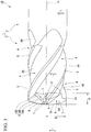
- a radius end mill 10 includes the end mill body 1 in the present embodiment.
- the end mill body 1 is integrally formed in a substantially columnar shape centered on an axial line O, using hard materials, such as cemented carbide.
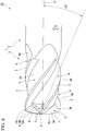
- a posterior end portion (an upper right portion of FIG. 1 and a right portion of FIGS. 3 and 4 ) of the end mill body 1 serves as a columnar shank portion 2.
- a tip portion (a lower left portion of FIG. 1 and a left portion of FIGS. 3 and 4 ) of the end mill body 1 serves as a cutting portion 3.
- a workpiece is subjected to cutting work by the cutting portion 3 while the shank portion 2 is gripped by a main shaft of a machine tool and is rotated around the axial line O.
- an end mill-rotational direction T a direction in which the radius end mill 10 rotates around the axial line O.
- Outer-peripheral-side ridge portions of wall faces 4A of the chip discharge grooves 4 that face the end mill-rotational direction T are respectively formed with peripheral cutting edges 5 having the wall faces 4A as rake faces.
- each wall face 4A forms a concave curve that is recessed to the side opposite to the end mill-rotational direction T in a section orthogonal to the axial line O. That is, each wall face 4A is formed in a curved manner so as to have a concave curve that is recessed to the side opposite to the end mill-rotational direction T as seen in the section orthogonal to the axial line O.
- the four peripheral cutting edges 5 are formed at regular intervals in the circumferential direction, similar to the chip discharge grooves 4, and a rotational locus that the peripheral cutting edges 5 draw around the axial line O becomes a single cylindrical surface centered on the axial line O.
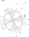
- a recessed groove-shaped gash 6 that extends toward the posterior end side as it becomes closer to an outer peripheral side of the end mill body 1 from the vicinity of the axial line O is formed at a tip portion of each chip discharge groove 4. More specifically, the gash 6 extends toward the posterior end side so as to cut out a groove bottom of the chip discharge groove 4 at the tip portion of the end mill body 1.
- a wall face 6A of each of the gashes 6 that faces the end mill-rotational direction T is formed so as to extend toward the side opposite the end mill-rotational direction T while being curved in a convex shape as it becomes closer to the outer peripheral side as illustrated in FIG 2 in the present embodiment.
- An end cutting edge 7 having the wall face 6A as a rake faces is formed at a tip-side ridge portion of the wall face 6A.
- a bottom face 6B that continues to the end mill-rotational direction T side with respect to the wall face 6A and faces a tip side in a direction of the axial line O, and a wall face 6C that further continues to the end mill-rotational direction T side with respect to the bottom face 6B and faces the side opposite to the end mill-rotational direction T are formed in each gash 6.
- a tip surface of the end mill body 1 that continues to the end mill-rotational direction T side with respect to the wall face 6C serves as a flank face 8 of the end cutting edge 7 adjacent to the end mill-rotational direction T side with respect to the end cutting edge 7 that continues to the gash 6 in which the wall face 6C is formed.
- a clearance angle is given to the flank face 8 so as to incline toward the posterior end side of the end mill body 1 as it becomes closer to the side opposite to the end mill-rotational direction T.
- flank face 8 is curvedly formed in a convex shape so as to face the posterior end side after protruding slightly to the tip side from the vicinity of the axial line O toward the outer peripheral side in the tip portion of the end mill body 1.
- the end cutting edge 7 is also formed in imitation of the flank face 8.
- the end cutting edge 7 has a protruded end 7A that protrudes toward the tip side in the direction of the axial line O at a position slightly apart from the axial line O to the outer peripheral side.
- the end cutting edge 7 is formed in a convexly curved shape that extends in a gently curved manner so as to face the posterior end side as it becomes closer to the outer peripheral side from the protruded end 7A.
- the end cutting edge 7 is formed so as to extend to the posterior end side as it becomes closer to the outer peripheral side of the end mill body 1 while a rotational locus thereof around the axial line O draws a protruded curved face from the protruded end 7A.
- the end cutting edge 7 that extends to the outer peripheral side of the tip portion of the end mill body 1 is in contact with the peripheral cutting edge 5 via a contact point 7B at an outer peripheral end thereof.
- the end cutting edge 7 is formed such that the curvature radius of a convex curve formed by a section along the axial line O of the protruded curved face formed by the end cutting edge 7 in the rotational locus around the axial line O becomes greater than that on a tip outer-peripheral side around the contact point 7B.
- the above protruded curved face is formed so as to have a convex curve where a curvature radius in an inner portion (for example, the protruded end 7A) located closer to the axial line O side than the tip outer-peripheral side is greater than a curvature radius on the tip outer-peripheral side (for example, the contact point 7B) of the end mill body 1, in a sectional view along the axial line O.
- a curvature radius in an inner portion for example, the protruded end 7A located closer to the axial line O side than the tip outer-peripheral side is greater than a curvature radius on the tip outer-peripheral side (for example, the contact point 7B) of the end mill body 1, in a sectional view along the axial line O.
- the curvature radius of the above convex curve formed by the section of the rotational locus of the end cutting edge 7 at the protruded end 7A is 5.0 mm
- the curvature radius of the above convex curve formed by the section of the rotational locus of the end cutting edge 7 at the contact point 7B is set to be 0.6 mm.
- the end cutting edge 7 is formed such that a plurality of (two in the present embodiment) circular arcs with that such different curvature radii are smoothly in contact with each other (are connected to each other).
- the wall face 6A (the rake face of the end cutting edge 7) of the gash 6 that faces the end mill-rotational direction T is formed in the shape of a twisted surface such that the inclination thereof with respect to the axial line O in a sectional view parallel to the axial line O as it becomes closer to the outer peripheral side of the end mill body 1 becomes larger in a direction facing the side opposite to the end mill-rotational direction T as it becomes closer to the posterior end side of the end mill body 1.
- FIG. 5 is a sectional view at the protruded end 7A of the end cutting edge 7.
- an axial rake angle ⁇ 1 (°) of the end cutting edge 7 at the protruded end 7A is set to be a negative angle.
- the axial rake angle of the end cutting edge 7 becomes a maximum on the positive angle side at the contact point 7B (the outer peripheral end of the end cutting edge 7) between the end cutting edge 7 and the peripheral cutting edge 5.
- the axial rake angle of the end cutting edge 7 is equal to the axial rake angle of the peripheral cutting edge 5, that is, the twist angle of the peripheral cutting edge 5, at the contact point 7B.
- an axial rake angle ⁇ 2 (°) of the end cutting edge 7 at the contact point 7B is set to be a positive angle.
- an intersection ridgeline L between the wall face 6A and the bottom face 6B of the gash 6 extends to the posterior end side beyond the contact point 7B in the direction of the axial line O. Also, as the intersection ridgeline L intersects the wall face 4A (the rake face of the peripheral cutting edge 5) of the chip discharge groove 4 that faces the end mill-rotational direction T, at the intersection point C, the gash 6 is formed in a cut-upward shape.
- intersection point C is the position of a most-posterior end of the gash 6.
- a gash depth angle 0 (°) given (calculated) by ⁇ tan -1 (A/B) on the basis of a distance A (mm) in the direction of the axial line O from the protruded end 7A of the end cutting edge 7 in the direction of the axial line O to the intersection point C serving as the most-posterior end of the gash 6, and a radius B (mm) from the axial line O to the contact point 7B between the peripheral cutting edge 5 and the end cutting edge 7 is set to be 50° or less.
- the gash depth angle 8 (°) represents the depth of the gash 6 to the posterior end side in the direction of the axial line O with respect to the radius B (mm) of the end cutting edge 7. Also, since the gash depth angle ⁇ (°) is set to be as small as 50° or less, the gash 6 is formed to be relatively shallow.
- the gash 6 of the end cutting edge 7 can be prevented from reducing the thickness of the tip portion of the end mill body 1 connected to the side, opposite to the end mill-rotational direction T, of another end cutting edge 7 or peripheral cutting edge 5 adjacent thereto the end mill-rotational direction T side.
- resistance can be reduced by sharpening the end cutting edge 7 at the contact point 7B, and chipping or the like at the contact point 7B can be prevented by suppressing occurrence of vibration.
- the gash depth angle ⁇ (°) is set to be 15° or more because the absolute capacity of the gash 6 become insufficient if this gash depth angle is too small.
- the axial rake angle difference ⁇ (°) is set to 10° or more. That is, 10° or more of the axial rake angle difference ⁇ (°) is secured between the protruded end 7A of the end cutting edge 7 and the contact point 7B.
- the wall face 6A (the rake face of the end cutting edge 7) of the gash 6 that faces the end mill-rotational direction T can be formed in the shape of a twisted surface as described above.
- chips which are generated by the end cutting edge 7 and scratch the wall face 6A, receive stress from the wall face 6A and are bent. For that reason, chips are discharged by being rapidly separating from the wall face 6A and sent out to the chip discharge groove 4.
- the radius end mill 10 of the above configuration even if the gash 6 becomes shallow by making the gash depth angle ⁇ (°) small as described above, good chip discharge performance can be guaranteed, and chips can be prevented from getting clogged within the gash 6. For that reason, an increase in resistance caused by chip clogging can be suppressed, and it is possible to perform stable cutting work.
- the sum ( ⁇ (°) + ⁇ (°)) of the gash depth angle ⁇ (°) and the axial rake angle difference ⁇ (°) ( ⁇ 2 (°) - ⁇ 1 (°)) is 80 degrees or more.
- the sum ( ⁇ (°) + ⁇ (°)) of the gash depth angle ⁇ (°) and the axial rake angle difference ⁇ (°) is set to be 80° or more.
- a total of four types of radius end mills including three types of radius end mills in which the sum ( ⁇ (°) + ⁇ (°)) of the gash depth angle ⁇ (°) and the axial rake angle difference ⁇ (°) is 50° that is less than 60°, and one type of a radius end mill in which the gash depth angle ⁇ (°) is 55° exceeding 50° were also manufactured.
- the radius end mills of these Examples 1 to 8 and Comparative Examples 1 to 4 are made of cemented carbide in which (Al, Ti, Si) N coating is performed on the surface of the end mill body 1, and as described in the above embodiment, the external diameter is set to be 6.0 mm (the radius B (mm) is 3.0 mm).
- a cutting edge length from the protruded end 7A to a posterior end of the peripheral cutting edge 5 is set to be 9 mm, and the clearance angle of the end cutting edge 7 and the peripheral cutting edge 5 is 15°.
- pockets were formed in a workpiece (hardness 60HRC) that made of SKD11 by contour line-working with a cut of 0.3 mm in the direction of the axial line O and a pick feed of 4.5 mm.
- the spindle speed of the end mill body 1 was 2500 min -1
- the feed rate thereof was 4500 mm/min.
- Example 1 Gash Depth Angle ⁇ (°) ⁇ (°) + ⁇ (°) Axial Rake Angle (°) Results Cutting Resistance (Resulting Force of Three Forces) Angle Difference ⁇ ( ⁇ 2- ⁇ 1) Protruded End ( ⁇ 1) Contact Point ( ⁇ 2)
- Example 1 40° 100° 60° -20° 40° A 652
- Example 2 40° 80° 40° -10° 30° A 640
- Example 3 30° 80° 50° -20° 30° A 691
- Example 4 50° 80° 30° -10° 20° A 716
- Example 5 50° 60° 10° 10° 20° B 805
- Example 6 40° 60° 20° -10° 10° B 827
- Example 7 30° 60° 30° -10° 20° B 833
- Example 8 20° 60° 40° -20° 20° B 889 Comparative Example 1 40° 50° 10° 0° 10° C 1350 Comparative Example 2 30° 50° 20° 0° 20° C 1488 Comparative Example 3 20° 50° 30°
- Example 8 in which the gash depth angle ⁇ (°) was 20° that was the same as that of Comparative Example 3, the axial rake angle difference ⁇ (°) was as large as 40° and chips could be sufficiently bent. Therefore, even if the depth of the gash 6 was small, chip clogging did not occur too.
- the invention even in a case where even the outer peripheral end of the end cutting edge is used for cutting, it is possible to perform stable cutting work that prevents chipping or the like resulting from vibration. Therefore, the invention has industrial applicability.
Landscapes
- Engineering & Computer Science (AREA)
- Mechanical Engineering (AREA)
- Milling Processes (AREA)
Applications Claiming Priority (2)
| Application Number | Priority Date | Filing Date | Title |
|---|---|---|---|
| JP2014206297A JP2016074061A (ja) | 2014-10-07 | 2014-10-07 | ラジアスエンドミル |
| PCT/JP2015/059973 WO2016056266A1 (fr) | 2014-10-07 | 2015-03-30 | Fraise en bout arrondie |
Publications (2)
| Publication Number | Publication Date |
|---|---|
| EP3205431A1 true EP3205431A1 (fr) | 2017-08-16 |
| EP3205431A4 EP3205431A4 (fr) | 2018-06-06 |
Family
ID=55652894
Family Applications (1)
| Application Number | Title | Priority Date | Filing Date |
|---|---|---|---|
| EP15848886.6A Withdrawn EP3205431A4 (fr) | 2014-10-07 | 2015-03-30 | Fraise en bout arrondie |
Country Status (6)
| Country | Link |
|---|---|
| US (1) | US20170304909A1 (fr) |
| EP (1) | EP3205431A4 (fr) |
| JP (1) | JP2016074061A (fr) |
| KR (1) | KR20170066368A (fr) |
| CN (1) | CN106794526A (fr) |
| WO (1) | WO2016056266A1 (fr) |
Families Citing this family (15)
| Publication number | Priority date | Publication date | Assignee | Title |
|---|---|---|---|---|
| US9975187B2 (en) * | 2014-10-28 | 2018-05-22 | Mitsubishi Hitachi Tool Engineering, Ltd. | Ceramic end mill and method for cutting difficult-to-cut material using the same |
| IL249676B (en) | 2016-12-20 | 2021-08-31 | Hanita Metal Works Ltd | An end mill with differently rotated slot profiles |
| CN108513549B (zh) * | 2016-12-26 | 2021-03-30 | 住友电工硬质合金株式会社 | 切削工具及其制造方法 |
| CN107984010B (zh) * | 2017-11-10 | 2019-07-09 | 株洲钻石切削刀具股份有限公司 | 一种圆角立铣刀 |
| JP6683299B2 (ja) | 2018-02-02 | 2020-04-15 | 三菱日立ツール株式会社 | エンドミルおよび加工方法 |
| JP7089171B2 (ja) * | 2018-05-23 | 2022-06-22 | 株式会社Moldino | エンドミル |
| ES1225597Y (es) * | 2019-02-05 | 2019-05-20 | Paragon Tools Sl | Herramienta de fresado para el asentamiento de un tornillo en una estructura dental |
| EP3736071B1 (fr) * | 2019-05-09 | 2022-03-16 | AB Sandvik Coromant | Fraise en bout monobloc |
| DE102019214041A1 (de) * | 2019-09-16 | 2021-03-18 | Gühring KG | Fräswerkzeug |
| CN113070517A (zh) * | 2020-01-06 | 2021-07-06 | 华硕电脑股份有限公司 | 用于加工金属壳体的端铣刀及加工方法 |
| CN113399727A (zh) * | 2021-04-16 | 2021-09-17 | 厦门金鹭特种合金有限公司 | 一种面铣精加工刀具 |
| KR102748743B1 (ko) * | 2021-09-20 | 2024-12-30 | 오에스지 가부시키가이샤 | 엔드밀 |
| US11865629B2 (en) | 2021-11-04 | 2024-01-09 | Kennametal Inc. | Rotary cutting tool with high ramp angle capability |
| EP4454794A4 (fr) * | 2021-12-24 | 2025-11-19 | Osg Corp | Fraise en bout |
| CN116900379B (zh) * | 2023-07-20 | 2025-10-31 | 湖南富兰地工具股份有限公司 | 圆鼻铣刀 |
Family Cites Families (10)
| Publication number | Priority date | Publication date | Assignee | Title |
|---|---|---|---|---|
| JP3638033B2 (ja) * | 1995-04-10 | 2005-04-13 | 日立ツール株式会社 | スローアウェイ式エンドミル |
| JPH11156620A (ja) * | 1997-11-25 | 1999-06-15 | Hitachi Tool Eng Ltd | 円弧刃エンドミル |
| JPH11216609A (ja) * | 1998-01-30 | 1999-08-10 | Hitachi Tool Eng Ltd | ラジアス刃エンドミル |
| DE10225481A1 (de) * | 2002-06-10 | 2003-12-18 | Sandvik Ab | Fräser mit Wiper-Radius |
| KR101029951B1 (ko) * | 2002-12-26 | 2011-04-19 | 미쓰비시 마테리알 가부시키가이샤 | 레디어스 엔드밀 |
| JP2006297495A (ja) * | 2005-04-15 | 2006-11-02 | Dijet Ind Co Ltd | ラジアスエンドミル |
| JP5194680B2 (ja) * | 2006-10-06 | 2013-05-08 | 三菱マテリアル株式会社 | ラジアスエンドミル |
| JP2011056608A (ja) * | 2009-09-08 | 2011-03-24 | Ki World:Kk | スクエアエンドミル |
| US8647025B2 (en) * | 2011-01-17 | 2014-02-11 | Kennametal Inc. | Monolithic ceramic end mill |
| US20150367429A1 (en) * | 2014-06-18 | 2015-12-24 | Sgs Tool Company | Rotary cutting tool |
-
2014
- 2014-10-07 JP JP2014206297A patent/JP2016074061A/ja active Pending
-
2015
- 2015-03-30 EP EP15848886.6A patent/EP3205431A4/fr not_active Withdrawn
- 2015-03-30 KR KR1020177008430A patent/KR20170066368A/ko not_active Withdrawn
- 2015-03-30 US US15/516,762 patent/US20170304909A1/en not_active Abandoned
- 2015-03-30 CN CN201580046845.7A patent/CN106794526A/zh active Pending
- 2015-03-30 WO PCT/JP2015/059973 patent/WO2016056266A1/fr not_active Ceased
Also Published As
| Publication number | Publication date |
|---|---|
| WO2016056266A1 (fr) | 2016-04-14 |
| EP3205431A4 (fr) | 2018-06-06 |
| CN106794526A (zh) | 2017-05-31 |
| US20170304909A1 (en) | 2017-10-26 |
| JP2016074061A (ja) | 2016-05-12 |
| KR20170066368A (ko) | 2017-06-14 |
Similar Documents
| Publication | Publication Date | Title |
|---|---|---|
| US20170304909A1 (en) | Radius end mill | |
| EP2913132B1 (fr) | Fraise à extrémité sphérique | |
| US10220451B2 (en) | End mill and method for manufacturing machined product | |
| EP3278913A1 (fr) | Fraise en bout formée | |
| EP2065111B1 (fr) | Outil de coupe rotatif | |
| CN102264496B (zh) | 圆弧头立铣刀 | |
| EP3733334A1 (fr) | Foret | |
| JP5842708B2 (ja) | ボールエンドミル | |
| JP2007030074A (ja) | ラジアスエンドミル及び切削加工方法 | |
| CN110446575B (zh) | 球头立铣刀 | |
| EP3560645A1 (fr) | Fraise en bout | |
| WO2019044791A1 (fr) | Alésoir conique | |
| WO2017043129A1 (fr) | Foret | |
| EP3865237A1 (fr) | Fraise en bout | |
| WO2016080486A1 (fr) | Plaquette de coupe et outil de coupe rotatif à bord de coupe remplaçable | |
| JP2013202748A (ja) | エンドミル | |
| JP5849817B2 (ja) | スクエアエンドミル | |
| US20250065422A1 (en) | Ball end mill | |
| JP6825400B2 (ja) | テーパボールエンドミル | |
| EP3812070B1 (fr) | Fraise à queue à rainurer | |
| JP5402575B2 (ja) | エンドミル | |
| CN116917073A (zh) | 立铣刀 | |
| EP3925721A1 (fr) | Fraise en bout | |
| JP2010030044A (ja) | ボールエンドミル | |
| WO2010050390A1 (fr) | Fraise à bout sphérique |
Legal Events
| Date | Code | Title | Description |
|---|---|---|---|
| PUAI | Public reference made under article 153(3) epc to a published international application that has entered the european phase |
Free format text: ORIGINAL CODE: 0009012 |
|
| 17P | Request for examination filed |
Effective date: 20170331 |
|
| AK | Designated contracting states |
Kind code of ref document: A1 Designated state(s): AL AT BE BG CH CY CZ DE DK EE ES FI FR GB GR HR HU IE IS IT LI LT LU LV MC MK MT NL NO PL PT RO RS SE SI SK SM TR |
|
| AX | Request for extension of the european patent |
Extension state: BA ME |
|
| DAV | Request for validation of the european patent (deleted) | ||
| DAX | Request for extension of the european patent (deleted) | ||
| A4 | Supplementary search report drawn up and despatched |
Effective date: 20180508 |
|
| RIC1 | Information provided on ipc code assigned before grant |
Ipc: B23C 5/10 20060101AFI20180502BHEP |
|
| STAA | Information on the status of an ep patent application or granted ep patent |
Free format text: STATUS: THE APPLICATION HAS BEEN WITHDRAWN |
|
| 18W | Application withdrawn |
Effective date: 20181011 |