EP3205441B1 - Électrodes de soudage et procédés de fabrication de celui-ci - Google Patents
Électrodes de soudage et procédés de fabrication de celui-ci Download PDFInfo
- Publication number
- EP3205441B1 EP3205441B1 EP16167944.4A EP16167944A EP3205441B1 EP 3205441 B1 EP3205441 B1 EP 3205441B1 EP 16167944 A EP16167944 A EP 16167944A EP 3205441 B1 EP3205441 B1 EP 3205441B1
- Authority
- EP
- European Patent Office
- Prior art keywords
- shell
- core
- wire
- shape
- assemblies
- Prior art date
- Legal status (The legal status is an assumption and is not a legal conclusion. Google has not performed a legal analysis and makes no representation as to the accuracy of the status listed.)
- Active
Links
Images








Classifications
-
- B—PERFORMING OPERATIONS; TRANSPORTING
- B23—MACHINE TOOLS; METAL-WORKING NOT OTHERWISE PROVIDED FOR
- B23K—SOLDERING OR UNSOLDERING; WELDING; CLADDING OR PLATING BY SOLDERING OR WELDING; CUTTING BY APPLYING HEAT LOCALLY, e.g. FLAME CUTTING; WORKING BY LASER BEAM
- B23K11/00—Resistance welding; Severing by resistance heating
- B23K11/30—Features relating to electrodes
-
- B—PERFORMING OPERATIONS; TRANSPORTING
- B21—MECHANICAL METAL-WORKING WITHOUT ESSENTIALLY REMOVING MATERIAL; PUNCHING METAL
- B21C—MANUFACTURE OF METAL SHEETS, WIRE, RODS, TUBES, PROFILES OR LIKE SEMI-MANUFACTURED PRODUCTS OTHERWISE THAN BY ROLLING; AUXILIARY OPERATIONS USED IN CONNECTION WITH METAL-WORKING WITHOUT ESSENTIALLY REMOVING MATERIAL
- B21C37/00—Manufacture of metal sheets, rods, wire, tubes, profiles or like semi-manufactured products, not otherwise provided for; Manufacture of tubes of special shape
- B21C37/04—Manufacture of metal sheets, rods, wire, tubes, profiles or like semi-manufactured products, not otherwise provided for; Manufacture of tubes of special shape of rods or wire
- B21C37/045—Manufacture of wire or rods with particular section or properties
-
- B—PERFORMING OPERATIONS; TRANSPORTING
- B21—MECHANICAL METAL-WORKING WITHOUT ESSENTIALLY REMOVING MATERIAL; PUNCHING METAL
- B21C—MANUFACTURE OF METAL SHEETS, WIRE, RODS, TUBES, PROFILES OR LIKE SEMI-MANUFACTURED PRODUCTS OTHERWISE THAN BY ROLLING; AUXILIARY OPERATIONS USED IN CONNECTION WITH METAL-WORKING WITHOUT ESSENTIALLY REMOVING MATERIAL
- B21C23/00—Extruding metal; Impact extrusion
- B21C23/22—Making metal-coated products; Making products from two or more metals
- B21C23/24—Covering indefinite lengths of metal or non-metal material with a metal coating
-
- B—PERFORMING OPERATIONS; TRANSPORTING
- B21—MECHANICAL METAL-WORKING WITHOUT ESSENTIALLY REMOVING MATERIAL; PUNCHING METAL
- B21C—MANUFACTURE OF METAL SHEETS, WIRE, RODS, TUBES, PROFILES OR LIKE SEMI-MANUFACTURED PRODUCTS OTHERWISE THAN BY ROLLING; AUXILIARY OPERATIONS USED IN CONNECTION WITH METAL-WORKING WITHOUT ESSENTIALLY REMOVING MATERIAL
- B21C33/00—Feeding extrusion presses with metal to be extruded ; Loading the dummy block
- B21C33/002—Encapsulated billet
-
- B—PERFORMING OPERATIONS; TRANSPORTING
- B21—MECHANICAL METAL-WORKING WITHOUT ESSENTIALLY REMOVING MATERIAL; PUNCHING METAL
- B21C—MANUFACTURE OF METAL SHEETS, WIRE, RODS, TUBES, PROFILES OR LIKE SEMI-MANUFACTURED PRODUCTS OTHERWISE THAN BY ROLLING; AUXILIARY OPERATIONS USED IN CONNECTION WITH METAL-WORKING WITHOUT ESSENTIALLY REMOVING MATERIAL
- B21C33/00—Feeding extrusion presses with metal to be extruded ; Loading the dummy block
- B21C33/004—Composite billet
-
- B—PERFORMING OPERATIONS; TRANSPORTING
- B22—CASTING; POWDER METALLURGY
- B22D—CASTING OF METALS; CASTING OF OTHER SUBSTANCES BY THE SAME PROCESSES OR DEVICES
- B22D11/00—Continuous casting of metals, i.e. casting in indefinite lengths
- B22D11/001—Continuous casting of metals, i.e. casting in indefinite lengths of specific alloys
- B22D11/004—Copper alloys
-
- B—PERFORMING OPERATIONS; TRANSPORTING
- B22—CASTING; POWDER METALLURGY
- B22D—CASTING OF METALS; CASTING OF OTHER SUBSTANCES BY THE SAME PROCESSES OR DEVICES
- B22D11/00—Continuous casting of metals, i.e. casting in indefinite lengths
- B22D11/006—Continuous casting of metals, i.e. casting in indefinite lengths of tubes
-
- B—PERFORMING OPERATIONS; TRANSPORTING
- B22—CASTING; POWDER METALLURGY
- B22D—CASTING OF METALS; CASTING OF OTHER SUBSTANCES BY THE SAME PROCESSES OR DEVICES
- B22D7/00—Casting ingots, e.g. from ferrous metals
- B22D7/005—Casting ingots, e.g. from ferrous metals from non-ferrous metals
-
- B—PERFORMING OPERATIONS; TRANSPORTING
- B22—CASTING; POWDER METALLURGY
- B22F—WORKING METALLIC POWDER; MANUFACTURE OF ARTICLES FROM METALLIC POWDER; MAKING METALLIC POWDER; APPARATUS OR DEVICES SPECIALLY ADAPTED FOR METALLIC POWDER
- B22F7/00—Manufacture of composite layers, workpieces, or articles, comprising metallic powder, by sintering the powder, with or without compacting wherein at least one part is obtained by sintering or compression
- B22F7/06—Manufacture of composite layers, workpieces, or articles, comprising metallic powder, by sintering the powder, with or without compacting wherein at least one part is obtained by sintering or compression of composite workpieces or articles from parts, e.g. to form tipped tools
- B22F7/08—Manufacture of composite layers, workpieces, or articles, comprising metallic powder, by sintering the powder, with or without compacting wherein at least one part is obtained by sintering or compression of composite workpieces or articles from parts, e.g. to form tipped tools with one or more parts not made from powder
-
- B—PERFORMING OPERATIONS; TRANSPORTING
- B23—MACHINE TOOLS; METAL-WORKING NOT OTHERWISE PROVIDED FOR
- B23K—SOLDERING OR UNSOLDERING; WELDING; CLADDING OR PLATING BY SOLDERING OR WELDING; CUTTING BY APPLYING HEAT LOCALLY, e.g. FLAME CUTTING; WORKING BY LASER BEAM
- B23K11/00—Resistance welding; Severing by resistance heating
- B23K11/30—Features relating to electrodes
- B23K11/3009—Pressure electrodes
-
- B—PERFORMING OPERATIONS; TRANSPORTING
- B23—MACHINE TOOLS; METAL-WORKING NOT OTHERWISE PROVIDED FOR
- B23K—SOLDERING OR UNSOLDERING; WELDING; CLADDING OR PLATING BY SOLDERING OR WELDING; CUTTING BY APPLYING HEAT LOCALLY, e.g. FLAME CUTTING; WORKING BY LASER BEAM
- B23K20/00—Non-electric welding by applying impact or other pressure, with or without the application of heat, e.g. cladding or plating
- B23K20/02—Non-electric welding by applying impact or other pressure, with or without the application of heat, e.g. cladding or plating by means of a press ; Diffusion bonding
- B23K20/021—Isostatic pressure welding
-
- B—PERFORMING OPERATIONS; TRANSPORTING
- B23—MACHINE TOOLS; METAL-WORKING NOT OTHERWISE PROVIDED FOR
- B23K—SOLDERING OR UNSOLDERING; WELDING; CLADDING OR PLATING BY SOLDERING OR WELDING; CUTTING BY APPLYING HEAT LOCALLY, e.g. FLAME CUTTING; WORKING BY LASER BEAM
- B23K20/00—Non-electric welding by applying impact or other pressure, with or without the application of heat, e.g. cladding or plating
- B23K20/22—Non-electric welding by applying impact or other pressure, with or without the application of heat, e.g. cladding or plating taking account of the properties of the materials to be welded
- B23K20/227—Non-electric welding by applying impact or other pressure, with or without the application of heat, e.g. cladding or plating taking account of the properties of the materials to be welded with ferrous layer
-
- B—PERFORMING OPERATIONS; TRANSPORTING
- B23—MACHINE TOOLS; METAL-WORKING NOT OTHERWISE PROVIDED FOR
- B23K—SOLDERING OR UNSOLDERING; WELDING; CLADDING OR PLATING BY SOLDERING OR WELDING; CUTTING BY APPLYING HEAT LOCALLY, e.g. FLAME CUTTING; WORKING BY LASER BEAM
- B23K20/00—Non-electric welding by applying impact or other pressure, with or without the application of heat, e.g. cladding or plating
- B23K20/22—Non-electric welding by applying impact or other pressure, with or without the application of heat, e.g. cladding or plating taking account of the properties of the materials to be welded
- B23K20/233—Non-electric welding by applying impact or other pressure, with or without the application of heat, e.g. cladding or plating taking account of the properties of the materials to be welded without ferrous layer
-
- B—PERFORMING OPERATIONS; TRANSPORTING
- B23—MACHINE TOOLS; METAL-WORKING NOT OTHERWISE PROVIDED FOR
- B23K—SOLDERING OR UNSOLDERING; WELDING; CLADDING OR PLATING BY SOLDERING OR WELDING; CUTTING BY APPLYING HEAT LOCALLY, e.g. FLAME CUTTING; WORKING BY LASER BEAM
- B23K35/00—Rods, electrodes, materials, or media, for use in soldering, welding, or cutting
- B23K35/02—Rods, electrodes, materials, or media, for use in soldering, welding, or cutting characterised by mechanical features, e.g. shape
- B23K35/0205—Non-consumable electrodes; C-electrodes
-
- B—PERFORMING OPERATIONS; TRANSPORTING
- B23—MACHINE TOOLS; METAL-WORKING NOT OTHERWISE PROVIDED FOR
- B23K—SOLDERING OR UNSOLDERING; WELDING; CLADDING OR PLATING BY SOLDERING OR WELDING; CUTTING BY APPLYING HEAT LOCALLY, e.g. FLAME CUTTING; WORKING BY LASER BEAM
- B23K35/00—Rods, electrodes, materials, or media, for use in soldering, welding, or cutting
- B23K35/02—Rods, electrodes, materials, or media, for use in soldering, welding, or cutting characterised by mechanical features, e.g. shape
- B23K35/0255—Rods, electrodes, materials, or media, for use in soldering, welding, or cutting characterised by mechanical features, e.g. shape for use in welding
- B23K35/0261—Rods, electrodes or wires
-
- B—PERFORMING OPERATIONS; TRANSPORTING
- B23—MACHINE TOOLS; METAL-WORKING NOT OTHERWISE PROVIDED FOR
- B23K—SOLDERING OR UNSOLDERING; WELDING; CLADDING OR PLATING BY SOLDERING OR WELDING; CUTTING BY APPLYING HEAT LOCALLY, e.g. FLAME CUTTING; WORKING BY LASER BEAM
- B23K35/00—Rods, electrodes, materials, or media, for use in soldering, welding, or cutting
- B23K35/22—Rods, electrodes, materials, or media, for use in soldering, welding, or cutting characterised by the composition or nature of the material
- B23K35/24—Selection of soldering or welding materials proper
- B23K35/30—Selection of soldering or welding materials proper with the principal constituent melting at less than 1550°C
- B23K35/302—Cu as the principal constituent
-
- B—PERFORMING OPERATIONS; TRANSPORTING
- B23—MACHINE TOOLS; METAL-WORKING NOT OTHERWISE PROVIDED FOR
- B23K—SOLDERING OR UNSOLDERING; WELDING; CLADDING OR PLATING BY SOLDERING OR WELDING; CUTTING BY APPLYING HEAT LOCALLY, e.g. FLAME CUTTING; WORKING BY LASER BEAM
- B23K35/00—Rods, electrodes, materials, or media, for use in soldering, welding, or cutting
- B23K35/40—Making wire or rods for soldering or welding
-
- B—PERFORMING OPERATIONS; TRANSPORTING
- B23—MACHINE TOOLS; METAL-WORKING NOT OTHERWISE PROVIDED FOR
- B23K—SOLDERING OR UNSOLDERING; WELDING; CLADDING OR PLATING BY SOLDERING OR WELDING; CUTTING BY APPLYING HEAT LOCALLY, e.g. FLAME CUTTING; WORKING BY LASER BEAM
- B23K35/00—Rods, electrodes, materials, or media, for use in soldering, welding, or cutting
- B23K35/40—Making wire or rods for soldering or welding
- B23K35/402—Non-consumable electrodes; C-electrodes
-
- B—PERFORMING OPERATIONS; TRANSPORTING
- B23—MACHINE TOOLS; METAL-WORKING NOT OTHERWISE PROVIDED FOR
- B23K—SOLDERING OR UNSOLDERING; WELDING; CLADDING OR PLATING BY SOLDERING OR WELDING; CUTTING BY APPLYING HEAT LOCALLY, e.g. FLAME CUTTING; WORKING BY LASER BEAM
- B23K35/00—Rods, electrodes, materials, or media, for use in soldering, welding, or cutting
- B23K35/40—Making wire or rods for soldering or welding
- B23K35/406—Filled tubular wire or rods
-
- B—PERFORMING OPERATIONS; TRANSPORTING
- B23—MACHINE TOOLS; METAL-WORKING NOT OTHERWISE PROVIDED FOR
- B23K—SOLDERING OR UNSOLDERING; WELDING; CLADDING OR PLATING BY SOLDERING OR WELDING; CUTTING BY APPLYING HEAT LOCALLY, e.g. FLAME CUTTING; WORKING BY LASER BEAM
- B23K2101/00—Articles made by soldering, welding or cutting
- B23K2101/36—Electric or electronic devices
- B23K2101/38—Conductors
-
- B—PERFORMING OPERATIONS; TRANSPORTING
- B23—MACHINE TOOLS; METAL-WORKING NOT OTHERWISE PROVIDED FOR
- B23K—SOLDERING OR UNSOLDERING; WELDING; CLADDING OR PLATING BY SOLDERING OR WELDING; CUTTING BY APPLYING HEAT LOCALLY, e.g. FLAME CUTTING; WORKING BY LASER BEAM
- B23K2103/00—Materials to be soldered, welded or cut
- B23K2103/08—Non-ferrous metals or alloys
- B23K2103/12—Copper or alloys thereof
-
- B—PERFORMING OPERATIONS; TRANSPORTING
- B23—MACHINE TOOLS; METAL-WORKING NOT OTHERWISE PROVIDED FOR
- B23K—SOLDERING OR UNSOLDERING; WELDING; CLADDING OR PLATING BY SOLDERING OR WELDING; CUTTING BY APPLYING HEAT LOCALLY, e.g. FLAME CUTTING; WORKING BY LASER BEAM
- B23K2103/00—Materials to be soldered, welded or cut
- B23K2103/18—Dissimilar materials
- B23K2103/22—Ferrous alloys and copper or alloys thereof
Definitions
- the disclosure generally relates to the field of composite wires and, in particular, methods for manufacture of resistance welding electrodes.
- DSC Dispersion Strengthened Copper
- DSC Dispersion Strengthened Copper
- extruded and drawn shapes including rounds, rectangles, wire, plates, tubes, and rolled strip.
- DSC is a thermally stable copper, which retains a high percentage of its strength at elevated temperatures. DSC does not recrystallize or soften after exposure to temperatures approaching the melting point of copper. Since DSC uses inert aluminum oxide particles to strengthen the copper matrix, the thermal conductivity of the copper is not significantly decreased.
- DSC is used for applications requiring electrical and thermal conductivity near that of pure copper, while maintaining strength and resistance to softening at elevated temperatures.
- the commercial applications for DSC include resistance welding electrodes, incandescent lamp lead wires, diodes, X-Ray and microwave tube components, high temperature contacts and particle accelerator components.
- DSC resistance welding electrodes offer improved life due to reduced weld tip surface softening and non-sticking properties when welding coated steels.
- the "canister method” is an example of DSC manufacturing, which begins with a canister made of pure copper.
- the canister is cleaned with an acid or alkaline cleaner to remove machining lubricants or any oxides from the surface.
- DSC powder is then placed into the canister to achieve a fill factor of between 50 to 55 percent.
- the canister can then be purged with nitrogen if desired and evacuated and sealed. This process of evacuating the canister creates a vacuum inside the canister to eliminate trapped gas and minimize expansion during preheating of the canister powder prior to extrusion. Heat can also be applied to the canisters during filling while creating the vacuum to remove any trapped moisture in the assembly. Once the vacuum has been established and moisture removed the canister is then sealed.
- the billet containing DSC powder is formed into rod by first preheating the billet to a given temperature and then extruding. Since the wall thickness of the canister is small (for example, less than 5 millimeters), a typical DSC rod may have a cross section of 92% DSC.
- the drawbacks to the canister method include: fabrication of a pure copper canister that adds no additional functional benefit to the final product, limited fill factor of powder into the canister creating low yields, the time required to evacuate a canister, increased heating time to heat an assembly prior to extrusion due to the separation between powder particles that reduces conduction heating, and an amount of DSC needed for the end product due to the small wall thickness.
- HIP and CIP have extreme costs associated with their operation. In particular, estimated cost per HIPing load using a large Quintus chamber would be $7,000 to $8,000 and having the capacity for 7k to 11k pounds of DSC billets. This would equate to approximately $0.833/lb. and would require a 24-hour cycle.
- the cost for CIPing is approximately $500 per item and takes approximately one hour to complete.
- the estimated cost for CIPing a DSC billet would be $2.00/lb.
- the cost of the canister method can be between $250-$500 per item.
- a disadvantage to HIP is that the assembled canisters containing DSC powder need to be heated to remove moisture, crimp sealed and welded, leak tested, and then HIPed.
- the fill factor must be greater than 50% prior to HIP. If the fill factor is less than 50% then the powder must be CIPed prior to being placed into a canister.
- DSC resistance welding electrodes.
- Resistance welding has long been used as a quick and effective method of joining metal members.
- the workpieces to be welded are placed in abutting relationship and a large current is caused to flow through the workpieces by a pair of opposed electrodes.
- the current causes the abutting surfaces of the workpieces to be heated sufficiently to effect the formation of a weld nugget.
- the electrodes apply significant pressure to the workpieces during welding. This facilitates the welding process by urging the material together and, also, reducing electrical resistance between each electrode tip and the adjacent workpiece material.
- the insert may be brazed onto the shank.
- the brazing step is disadvantageous as it adds an additional step to the electrode manufacturing process and, hence, increases the cost of the electrode. Furthermore, the brazing operation may anneal and soften the electrode body.
- US 2005/0092728 discloses a method of manufacturing a welding electrode using the so called "canister method.
- a billet which is to form the core of an electrode is formed by extrusion of a sealed copper container (canister) in which a lightly compacted copper based alloy powder is held.
- the billet is inserted into a tube which is to form the shell of the electrode.
- the shell and billet are thereafter coextruded to form a composite product, which is then cold worked to form the electrode.
- the technical problem in view of 2005/0092728 is to provide a method for manufacturing a welding electrode having an improved electrical performance as well as durability and weld nugget stability.
- US 4345136 discloses a resistance welding electrode having a dispersion strengthened copper tip and a high conductivity copper shank.
- the electrode is made by forming a tip member in two successive upsetting operations to produce a tip member having a coating of high conductivity copper covering substantially all of one end thereof.
- a solid, high conductivity copper, cylindrical billet is formed and brazed to the tip member as its coated end to form an extrusion blank.
- the extrusion blank is back extruded with the high conductivity copper material being worked substantially, while only partially back extruding the tip portion of the extrusion blank.
- the present disclosure provides a method 100 of manufacturing a composite material.
- the method 100 can include compacting 110 a copper alloy powder into a plurality of substantially uniform compressed sub-assemblies such that the copper alloy powder can have a density that is greater than 70%, 75%, 80%, or 85% according to certain embodiments of the present disclosure.
- the plurality of compressed sub-assemblies can be layered 120 relative one another within an aperture of a shell, the plurality of compressed sub-assemblies to form a consecutive assembly of compacted copper alloy.
- the consecutive assembly can be sealed 130 within the shell to form a billet.
- the billet can be purged 140 with gas, and hot extruded 150.
- the extruded billet is used to draw 160 a composite material.
- FIG. 2 shows an exemplary shell 25 that may be used in accordance with the method 100.
- the shell 25 may be the product of various fabrication methods.
- the shell may be cast by: continuous casting of a hollow cross section, continuous casting of a solid billet, sand casting, vacuum casting, or billet casting.
- methods may include machining of the inner diameter from a solid billet, back extruding the inner diameter from a solid billet, or inserting and welding a plug into a hollow cross section.
- the wall thickness 23 of the shell 25 may be extruded, machined, or cast to a desired thickness.
- the wall thickness 23 may be minimal (for example, a minimum of about 2mm), while others may require a wall thickness 23 that covers up a substantial portion of the cross section (for example, a maximum of about 5mm). It may be desired to reduce the amount of copper alloy required for the core, so the core may make up no more than 25% of the cross section.
- the shell 25 may further be cleaned to remove any impurities left behind by the fabrication process, for instance, an acid dip.
- the shape of the shell 25 can be a hollow cylindrical or prismatic volume with a cavity that includes an aperture 20 on one face and extends a substantial length of the shell 25.
- the thickness 23 is 52.5 mm and the length 22 is 470 mm.
- the shell 25 may be formed of one or more of the following materials: a precipitation hardened copper alloy, copper alloy, or carbon steel.
- the method 100 can include compressing DSC powder into a plurality of compressed sub-assemblies 15. This process can begin by forming the DSC powder 10 using internal oxidation or mechanical milling techniques. Once the DSC powder 10 is produced, a gravimetric or volumetric method may be used to obtain a predetermined amount of powder to produce a specific size sub-assembly 15. The predetermined amount of powder may be compacted 110 using a mechanical or hydraulic press to create a sub-assembly 15 of a density greater than 70%. In one embodiment, the powder density of the sub-assemblies may be 85%. Depending on the quality of the powder 10, the compacted sub-assemblies 15 may be also thermally heat treated 115. This may be performed using hydrogen to remove any moisture, residual lubricants from the pressing operation, or residual copper oxides.
- Figure 3 depicts an exemplary sub-assembly that may be used according to the method 100.
- the shape of the compacted sub-assemblies 15 can change depending on the desired fit within the aperture 20 of the shell 25.
- Examples of sub-assembly 15 shapes include cylindrical and prismatic volumes.
- the shape of the shell 25 is cylindrical such that the shape of the compressed sub-assembly 15 is also cylindrical, with a thickness 13 and diameter 12 that complements the aperture 20 diameter of the shell 25.
- the thickness 13 can range from 25-50mm and diameter 12 can range from 70-200mm. In a specific embodiment, the thickness 13 is 25.5 mm and the diameter 12 is 100.3 mm
- the shell 25 can be made of CuZr, and the powder 10 be DSC.
- the density of the DSC powder 10 can be greater than 65%.
- the compressed sub-assemblies 15 are thermally heat treated 115 prior to being layered 120 within the shell 25.
- the shell 25 material chosen was a precipitation hardened copper alloy. Since the shell material is only used as a device to contain the DSC, any copper or nonferrous alloy compatible with the extrusion temperature and having similar elongation properties to that of the DSC may be selected. Carbon steel may also be selected.
- a layer of un-compacted copper alloy powder 10 may be provided 116 in the shell if it was produced using back extrusion or machining. This may compensate for any surface irregularities or air gaps from machining or extrusion contours.
- Compressed sub-assemblies 15 are layered 120 within the aperture 20 of the shell 25, with each sub-assembly 15 in contact with the faces of the adjacent layers. The number of sub-assemblies 15 that comprise the plurality is dependent on the thickness 13 of each sub-assembly and the length 22 of the shell 25 used.
- the number of sub-assemblies 15 may be relatively large if the thickness 13 of each sub-assembly 15 is relatively short and the length 22 of the shell 25 is relatively long, and the number of sub-assemblies 15 may be relatively small if the thickness 13 of each sub-assembly 15 is relatively long and the length 22 of the shell 25 is relatively short.
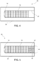
- This consecutive assembly 30 of Fig. 4 is sealed 130 and purged 140 with nitrogen.
- Sealing 130 involves installing a cap 40 on top of the plurality of sub-assemblies 15 within the aperture 20 of the shell 25 and welding it in place to form billet 35, as seen in Fig. 5 .
- Weld nugget 44 may be the result of any welding process one of ordinary skill in the art may be familiar with.
- the cap 40 may further contain a tube 45, as seen in Fig. 6 , to facilitate gas purging and evacuation of the shell cavity.
- Fig. 7 depicts two billets 35 undergoing the purging step 140.
- the purging step 140 includes addition of the purging gas, which may be nitrogen, heating the billet above ambient temperature of the consecutive assembly, and evacuation of the purging gas.
- the billet 35 may be heated to a temperature above 900°C. In a specific embodiment, the billet 35 may be heated to a temperature of 960°C.
- the heated billet 35 may then be extruded 150 into a rod 50, as seen in Fig. 8A , and water quenched upon the exit of the extrusion die. Through extrusion 150, the interfaces between the compacted sub-assemblies 15 are completely bonded together, as well as the interface between the plurality of sub-assemblies 15 and the shell 25, as seen in Fig. 8B .
- Fig. 9 An enhanced view of the extruded rod is shown in Fig. 9 .
- the extruded rod 50 is further drawn 160 to form a composite wire 55 having the desired diameter.
- Conventional drawing techniques may be used, which may involve multiple passes to achieve the desired diameter. If a precipitation hardened copper alloy is used in the assembly for the shell material, a heat treatment step may be necessary to harden and increase the conductivity of the shell material.
- the final composite wire coil 55 is shown in Fig. 10 and a sheared end of a composite wire is shown in Fig. 11 .
- the method of producing a DSC rod simplifies the production process and can be used to reduce the amount of DSC needed for the end product. All known current methods used to produce DSC rod start from either extruding granule/powder within a canister or extruding CIPed/HIPed billets. Instead, the present disclosure uses pre-compacted sub-assemblies from granules/powder that are stacked into a tubular shell and then extruded into rod.
- the benefits to this method include: larger coil weights of extruded DSC rod due to using DSC powder that has been compacted to a density greater than 80% prior to extrusion and the ability to significantly increase the wall thickness of the outer shell to minimize the amount of DSC for specific products, including welding . Utilizing this method to manufacture a rod with significantly less DSC is the primary focus of this work and its relationship to resistance welding electrodes.
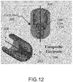
- the present disclosure describes a composite welding electrode 200.
- the electrode 200 comprises a composite body having a tip portion 203 and an end portion 204.
- the composite body of the electrode 200 includes a shell 205 defining a cavity 206 through the end portion 204.
- the shell 205 is comprised of a first metal that includes precipitation hardened copper alloy, copper alloy, or carbon steel.
- the shell 205 further comprises a core 210 within the shell 205, the core 210 extending through the shell 205 from the tip portion 203 to the cavity 206.
- the core 210 comprises a second metal that includes dispersion strengthened copper.
- the core 210 and shell 205 have a metallurgical bond formed from co-extrusion .
- the diameter of the core 210 may be substantially uniform from the tip portion 203 of the electrode 200 or the majority of the length of the core 210 may have a diameter that is substantially uniform with a minority length of the diameter that tapers outwardly as the core 210 meets the cavity 206.
- the cavity 206 of the electrode 200 may be sized and configured to be received by a robotic welder.
- the cavity 206 may be tapered inwardly from the end portion 204 to the core 210.
- the tip portion 203 may have a cross-sectional shape of a truncated parabolic or elliptical curve.
- the core 210 has an axial length and the shell 205 has an axial length, where the axial length of the core 210 may be about half the axial length of the shell 205.
- the shell 205 can be made solely of CuZr and the core 210 made solely from dispersion strengthened copper.
- the core 210 may have a diameter that is 6-8mm at the tip portion 203 of the body, or the diameter of the core 210 may be approximately 6-8mm throughout the welding electrode 200.
- the shell 205 can have an outer diameter that is approximately 0.600-0.650 inches and an inner diameter that is approximately 0.420-0.480 inches, which forms an outer wall of the cavity 210.
- the core 210 may have a melting point of approximately 1083°C (1981°F); a hardness range of approximately 110-125 HV (60-70 HRB); an electrical conductivity of approximately 0.380 MegaSiemens/cm at 20°C (83% IACS at 68°F); and a density of approximately 8.83 gm/cm 3 at 20°C (0.319 lb/in 3 at 68°F).
- the shell 205 may have a melting range of approximately 980°C-1080°C (796°F-1976°F); a density of approximately 8.89 gm/cm3 at 20°C (0.321 lb/in 3 at 68°F); and a thermal conductivity of approximately 366.9 W/m ⁇ °K at 20°C (212.0 Btu ft/(hr ⁇ ft 2 ⁇ °F) at 68°F).
- the shell 205 can have a hardness of approximately 120-155 HV (64-80 HRB); an electrical conductivity of approximately 0.544 MegaSiemens/cm at 20°C (93%IACS at 68°F); an electrical resistivity of approximately 1.86 microhm-cm at 20°C (11.2 ohms-cmil/ft at 68°F); a specific gravity of approximately 8.89; and a specific heat capacity of approximately 393.5 J/kg ⁇ °K at 293°K (0.092 Btu/lb/°F at 68°F).
- the present disclosure further comprises a method 300 of manufacturing a composite material.
- the method 300 includes providing 310 a composite metal wire having a first end and a second end, a core, and a shell surrounding the core where a metallurgical bond is formed between the shell and core from co-extrusion.
- the composite metal wire is cylindrical and the core extends from the first end to the second end of the composite metal wire.
- the shell comprises precipitation hardened copper alloy or carbon steel and the core comprises dispersion strengthened copper.
- the shell may be made solely of CuZr and the core made be made solely from dispersion strengthened copper.
- the composite wire can be deformed 320 into a first shape such that the first end forms as rounded tip having a truncation.
- the step of deforming 320 the wire into the first shape may lengthen the wire. Multiple deforming presses may be necessary to achieve the first shape.
- the first shape is further deformed 330 into a second shape in which a cavity is formed in the second end.
- the deforming step 330 from the first shape to the second shape may involve pushing the core from the second end toward the first end. Multiple deforming presses may be necessary to achieve the second shape.
- the step of deforming 330 the wire from the first shape into the second shape may also lengthen the wire.
- the core may have an axial length and the shell has an axial length, where the axial length of the core may be about half the axial length of the shell.
- Figures 16A-16F show cross-sectional views of an exemplary composite wire undergoing an exemplary manufacturing method according to the present disclosure. Specifically, an initial composite wire, shown in Fig.16A , is shown undergoing five successive deformation steps Figs. 16B-16F , until a composite welding electrode is formed.
- Benefits of the methods of manufacturing a composite material and the composite welding electrode described herein include: improved weld nugget stability due to a consistent diameter of core, extended welding electrode life due to lower expansion of the weld face of the electrode, improved electrical efficiencies by using alloys with higher electrical conductivities for the outer shell, improved electrode cooling by using alloys with higher thermal conductivities for the outer shell, and the ability to have an infinite range of core diameter to shell diameter ratios.
- the overall cost of welding can be reduced, while maintaining a high weld quality.
- the improved electrical efficiencies can reduce the weld currents used during a welding operation.
Landscapes
- Engineering & Computer Science (AREA)
- Mechanical Engineering (AREA)
- Chemical & Material Sciences (AREA)
- Composite Materials (AREA)
- Manufacturing & Machinery (AREA)
- Materials Engineering (AREA)
- Powder Metallurgy (AREA)
Claims (8)
- Procédé de fabrication d'une électrode de soudage, comprenant :le compactage d'une poudre d'alliage de cuivre en une pluralité de sous-ensembles (15) comprimés d'une manière sensiblement uniforme de manière à ce que la poudre d'alliage de cuivre de la pluralité de sous-ensembles (15) comprimés ait une densité de tassement qui est plus grande que 50%;la mise en couche de la pluralité de sous-ensembles (15) comprimés les uns par rapport aux autres dans une ouverture (20) d'une coquille (25), la pluralité de sous-ensembles (15) comprimés formant un ensemble (30) consécutif d'alliage de cuivre compacté;le scellement de l'ensemble (30) consécutif dans la coquille (25) pour former une billette (35);l'extrusion à chaud de la billette à une température supérieure à 900°C en un fil (55) métallique composite ayant une première extrémité et une seconde extrémité, le fil (55) composite ayant une âme et une gaine entourant l'âme, l'âme et la gaine ayant une liaison métallurgique formée par coextrusion;la déformation du fil (55) en une première forme de manière à ce que la première extrémité forme un bout arrondi ayant une troncature;la déformation du fil (55) de la première forme à une seconde forme de manière à former une cavité à la seconde extrémité;la déformation du fil (55) de la deuxième forme en une électrode composite de soudage;dans lequel déformer le fil (55) de la première forme en la deuxième forme pousse l'âme de la seconde extrémité vers la première extrémité;dans lequel la gaine comprend l'un de ce qui suit : un alliage de cuivre durci par précipitation, un alliage de cuivre et un acier au carbone;dans lequel l'âme (210) comprend du cuivre à durcissement par phase dispersée;dans lequel l'âme (210) de l'électrode composite de soudage a un diamètre, qui augmente du bout arrondi vers la cavité (206) .
- Procédé suivant la revendication 1, dans lequel la gaine est faite seulement de CuZr et/ou dans lequel l'âme (210) est faite seulement de cuivre à durcissement par phase dispersée.
- Procédé suivant la revendication 1 ou 2, dans lequel le fil (55) composite métallique est cylindrique, l'âme s'étendant de la première extrémité à la seconde extrémité du fil (55) composite métallique.
- Procédé suivant l'une quelconque des revendications 1 à 3, dans lequel la déformation du fil (55) en la première forme allonge le fil (55) et/ou dans lequel la déformation du fil (55) de la première forme à la deuxième forme allonge le fil (55) .
- Procédé suivant l'une quelconque des revendications 1 à 4, dans lequel, dans la deuxième forme, l'âme a une longueur axiale et la gaine a une longueur axiale, la longueur axiale de l'âme représentant environ la moitié de la longueur axiale de la gaine.
- Procédé suivant l'une quelconque des revendications 1 à 5, dans lequel la densité de tassement de la poudre d'alliage de cuivre de la pluralité de sous-ensembles (15) comprimés est plus grande que 65%.
- Procédé suivant l'une quelconque des revendications 1 à 6, comprenant en outre un traitement thermique à la chaleur des sous-ensembles (15) comprimés avant la mise en couche de la pluralité de sous-ensembles (15) comprimés dans la coquille.
- Procédé suivant l'une quelconque des revendications 1 à 7, comprenant, en outre, mettre une couche de poudre d'alliage de cuivre non compactée dans la coquille ;
la pluralité de sous-ensembles (15) comprimés étant mise en couche sur la couche de poudre d'alliage de cuivre non compactée.
Applications Claiming Priority (1)
| Application Number | Priority Date | Filing Date | Title |
|---|---|---|---|
| US15/040,398 US10207355B2 (en) | 2016-02-10 | 2016-02-10 | Welding electrodes and methods of manufacturing same |
Publications (2)
| Publication Number | Publication Date |
|---|---|
| EP3205441A1 EP3205441A1 (fr) | 2017-08-16 |
| EP3205441B1 true EP3205441B1 (fr) | 2021-06-30 |
Family
ID=55910170
Family Applications (1)
| Application Number | Title | Priority Date | Filing Date |
|---|---|---|---|
| EP16167944.4A Active EP3205441B1 (fr) | 2016-02-10 | 2016-05-02 | Électrodes de soudage et procédés de fabrication de celui-ci |
Country Status (2)
| Country | Link |
|---|---|
| US (1) | US10207355B2 (fr) |
| EP (1) | EP3205441B1 (fr) |
Cited By (1)
| Publication number | Priority date | Publication date | Assignee | Title |
|---|---|---|---|---|
| DE102022103617A1 (de) | 2022-02-16 | 2023-08-17 | Cunova Gmbh | Verfahren zur Herstellung einer Schweißkappe und Schweißkappe |
Families Citing this family (2)
| Publication number | Priority date | Publication date | Assignee | Title |
|---|---|---|---|---|
| WO2017151737A1 (fr) * | 2016-03-03 | 2017-09-08 | H.C. Starck Inc. | Fabrication de pièces métalliques par fabrication additive |
| EP3461921B1 (fr) * | 2016-12-01 | 2021-06-02 | NGK Insulators, Ltd. | Élément support éléctroconduteur et procédé de fabrication d'un tel élément support éléctroconduteur |
Family Cites Families (7)
| Publication number | Priority date | Publication date | Assignee | Title |
|---|---|---|---|---|
| US3909581A (en) * | 1972-05-08 | 1975-09-30 | Mallory & Co Inc P R | Disposable resistance welding electrode |
| US4071947A (en) | 1976-12-13 | 1978-02-07 | The Nippert Company | Bimetal resistance welding electrode and method for making |
| US4345136A (en) | 1978-11-13 | 1982-08-17 | The Nippert Company | Copper bimetal brazed resistance welding electrode |
| US4588870A (en) * | 1984-12-18 | 1986-05-13 | Scm Corporation | Resistance welding electrode cap |
| US5030275A (en) | 1987-12-14 | 1991-07-09 | Scm Metal Products, Inc. | Equiaxed dispersion strengthened copper product |
| JPH0976074A (ja) | 1995-09-12 | 1997-03-25 | Kobe Steel Ltd | 抵抗溶接用電極材及び抵抗溶接用複合電極並びにその製造方法 |
| FR2859401B1 (fr) * | 2003-09-10 | 2006-03-17 | Le Bronze Ind Sa | Electrode de soudage par resistance et son procede de fabrication |
-
2016
- 2016-02-10 US US15/040,398 patent/US10207355B2/en active Active
- 2016-05-02 EP EP16167944.4A patent/EP3205441B1/fr active Active
Non-Patent Citations (1)
| Title |
|---|
| None * |
Cited By (2)
| Publication number | Priority date | Publication date | Assignee | Title |
|---|---|---|---|---|
| DE102022103617A1 (de) | 2022-02-16 | 2023-08-17 | Cunova Gmbh | Verfahren zur Herstellung einer Schweißkappe und Schweißkappe |
| WO2023155954A1 (fr) | 2022-02-16 | 2023-08-24 | Cunova Gmbh | Procédé de fabrication d'un capuchon de soudage et capuchon de soudage |
Also Published As
| Publication number | Publication date |
|---|---|
| US10207355B2 (en) | 2019-02-19 |
| US20170225261A1 (en) | 2017-08-10 |
| EP3205441A1 (fr) | 2017-08-16 |
Similar Documents
| Publication | Publication Date | Title |
|---|---|---|
| JP4896032B2 (ja) | 管状ターゲット | |
| CA1186874A (fr) | Methode de production d'electrodes males pour le soudage par resistance | |
| EP0202735B1 (fr) | Procédé pour la fabrication d'une ébauche composite à partir de poudre métallique | |
| CA1198267A (fr) | Methode de fabrication de tubes bimetalliques | |
| EP0011466B1 (fr) | Electrode de soudage par résistance bimétallique et procédé pour sa fabrication | |
| CN102226486B (zh) | 一种铜铝双金属复合管及其模具挤压成型方法 | |
| US20050092728A1 (en) | Resistance welding electrode and associated manufacturing method | |
| EP3205441B1 (fr) | Électrodes de soudage et procédés de fabrication de celui-ci | |
| JP2005506200A5 (fr) | ||
| JP5244063B2 (ja) | アルミニウム材の電磁成形方法 | |
| US5844194A (en) | Resistance welding electrode and method of manufacturing same | |
| US4345136A (en) | Copper bimetal brazed resistance welding electrode | |
| US4933141A (en) | Method for making a clad metal product | |
| US10300531B2 (en) | Methods of manufacturing composite materials, composite wires, and welding electrodes | |
| US10730135B2 (en) | Welding electrodes and adapter therefor | |
| CN113976658B (zh) | 一种超大规格钛合金管材的制备方法 | |
| US4958060A (en) | Clad metal electrode | |
| WO1996024455A1 (fr) | Procede d'extrusion de poudres metalliques dont le tantale et le niobium | |
| US4110130A (en) | Forging powdered dispersion strengthened metal | |
| US3523354A (en) | Method of producing large shapes | |
| CN107322179A (zh) | 一种低温自钎剂铝硅焊环 | |
| CN111438362A (zh) | 一种热挤压包套及使用包套生产预成型件的方法 | |
| US20040219050A1 (en) | Superdeformable/high strength metal alloys | |
| US3913208A (en) | Process for producing bimetallic and polymetallic bodies in which the metallic components are joined together with metallurgical bond | |
| KR100573314B1 (ko) | 알루미늄 부품 제조방법과 이를 이용하여 제조된 콘덴서튜브 및 고력 알루미늄 합금재 부품 |
Legal Events
| Date | Code | Title | Description |
|---|---|---|---|
| PUAI | Public reference made under article 153(3) epc to a published international application that has entered the european phase |
Free format text: ORIGINAL CODE: 0009012 |
|
| STAA | Information on the status of an ep patent application or granted ep patent |
Free format text: STATUS: THE APPLICATION HAS BEEN PUBLISHED |
|
| AK | Designated contracting states |
Kind code of ref document: A1 Designated state(s): AL AT BE BG CH CY CZ DE DK EE ES FI FR GB GR HR HU IE IS IT LI LT LU LV MC MK MT NL NO PL PT RO RS SE SI SK SM TR |
|
| AX | Request for extension of the european patent |
Extension state: BA ME |
|
| STAA | Information on the status of an ep patent application or granted ep patent |
Free format text: STATUS: REQUEST FOR EXAMINATION WAS MADE |
|
| 17P | Request for examination filed |
Effective date: 20180213 |
|
| RBV | Designated contracting states (corrected) |
Designated state(s): AL AT BE BG CH CY CZ DE DK EE ES FI FR GB GR HR HU IE IS IT LI LT LU LV MC MK MT NL NO PL PT RO RS SE SI SK SM TR |
|
| STAA | Information on the status of an ep patent application or granted ep patent |
Free format text: STATUS: EXAMINATION IS IN PROGRESS |
|
| 17Q | First examination report despatched |
Effective date: 20200514 |
|
| RIC1 | Information provided on ipc code assigned before grant |
Ipc: B22D 11/00 20060101ALI20201126BHEP Ipc: B21C 33/00 20060101ALI20201126BHEP Ipc: B23K 35/40 20060101AFI20201126BHEP Ipc: B23K 11/00 20060101ALI20201126BHEP Ipc: B23K 35/02 20060101ALI20201126BHEP Ipc: B22D 7/00 20060101ALI20201126BHEP Ipc: B23K 11/30 20060101ALI20201126BHEP Ipc: B23K 20/227 20060101ALI20201126BHEP Ipc: B23K 20/02 20060101ALI20201126BHEP Ipc: B21C 37/04 20060101ALI20201126BHEP Ipc: B23K 35/30 20060101ALI20201126BHEP |
|
| GRAP | Despatch of communication of intention to grant a patent |
Free format text: ORIGINAL CODE: EPIDOSNIGR1 |
|
| STAA | Information on the status of an ep patent application or granted ep patent |
Free format text: STATUS: GRANT OF PATENT IS INTENDED |
|
| INTG | Intention to grant announced |
Effective date: 20210114 |
|
| GRAS | Grant fee paid |
Free format text: ORIGINAL CODE: EPIDOSNIGR3 |
|
| GRAA | (expected) grant |
Free format text: ORIGINAL CODE: 0009210 |
|
| STAA | Information on the status of an ep patent application or granted ep patent |
Free format text: STATUS: THE PATENT HAS BEEN GRANTED |
|
| AK | Designated contracting states |
Kind code of ref document: B1 Designated state(s): AL AT BE BG CH CY CZ DE DK EE ES FI FR GB GR HR HU IE IS IT LI LT LU LV MC MK MT NL NO PL PT RO RS SE SI SK SM TR |
|
| REG | Reference to a national code |
Ref country code: CH Ref legal event code: EP |
|
| REG | Reference to a national code |
Ref country code: AT Ref legal event code: REF Ref document number: 1405899 Country of ref document: AT Kind code of ref document: T Effective date: 20210715 |
|
| REG | Reference to a national code |
Ref country code: DE Ref legal event code: R096 Ref document number: 602016059880 Country of ref document: DE |
|
| REG | Reference to a national code |
Ref country code: IE Ref legal event code: FG4D |
|
| REG | Reference to a national code |
Ref country code: LT Ref legal event code: MG9D |
|
| PG25 | Lapsed in a contracting state [announced via postgrant information from national office to epo] |
Ref country code: BG Free format text: LAPSE BECAUSE OF FAILURE TO SUBMIT A TRANSLATION OF THE DESCRIPTION OR TO PAY THE FEE WITHIN THE PRESCRIBED TIME-LIMIT Effective date: 20210930 Ref country code: HR Free format text: LAPSE BECAUSE OF FAILURE TO SUBMIT A TRANSLATION OF THE DESCRIPTION OR TO PAY THE FEE WITHIN THE PRESCRIBED TIME-LIMIT Effective date: 20210630 Ref country code: FI Free format text: LAPSE BECAUSE OF FAILURE TO SUBMIT A TRANSLATION OF THE DESCRIPTION OR TO PAY THE FEE WITHIN THE PRESCRIBED TIME-LIMIT Effective date: 20210630 |
|
| REG | Reference to a national code |
Ref country code: NL Ref legal event code: MP Effective date: 20210630 |
|
| REG | Reference to a national code |
Ref country code: AT Ref legal event code: MK05 Ref document number: 1405899 Country of ref document: AT Kind code of ref document: T Effective date: 20210630 |
|
| PG25 | Lapsed in a contracting state [announced via postgrant information from national office to epo] |
Ref country code: NO Free format text: LAPSE BECAUSE OF FAILURE TO SUBMIT A TRANSLATION OF THE DESCRIPTION OR TO PAY THE FEE WITHIN THE PRESCRIBED TIME-LIMIT Effective date: 20210930 Ref country code: RS Free format text: LAPSE BECAUSE OF FAILURE TO SUBMIT A TRANSLATION OF THE DESCRIPTION OR TO PAY THE FEE WITHIN THE PRESCRIBED TIME-LIMIT Effective date: 20210630 Ref country code: SE Free format text: LAPSE BECAUSE OF FAILURE TO SUBMIT A TRANSLATION OF THE DESCRIPTION OR TO PAY THE FEE WITHIN THE PRESCRIBED TIME-LIMIT Effective date: 20210630 Ref country code: LV Free format text: LAPSE BECAUSE OF FAILURE TO SUBMIT A TRANSLATION OF THE DESCRIPTION OR TO PAY THE FEE WITHIN THE PRESCRIBED TIME-LIMIT Effective date: 20210630 Ref country code: GR Free format text: LAPSE BECAUSE OF FAILURE TO SUBMIT A TRANSLATION OF THE DESCRIPTION OR TO PAY THE FEE WITHIN THE PRESCRIBED TIME-LIMIT Effective date: 20211001 |
|
| PG25 | Lapsed in a contracting state [announced via postgrant information from national office to epo] |
Ref country code: SM Free format text: LAPSE BECAUSE OF FAILURE TO SUBMIT A TRANSLATION OF THE DESCRIPTION OR TO PAY THE FEE WITHIN THE PRESCRIBED TIME-LIMIT Effective date: 20210630 Ref country code: SK Free format text: LAPSE BECAUSE OF FAILURE TO SUBMIT A TRANSLATION OF THE DESCRIPTION OR TO PAY THE FEE WITHIN THE PRESCRIBED TIME-LIMIT Effective date: 20210630 Ref country code: EE Free format text: LAPSE BECAUSE OF FAILURE TO SUBMIT A TRANSLATION OF THE DESCRIPTION OR TO PAY THE FEE WITHIN THE PRESCRIBED TIME-LIMIT Effective date: 20210630 Ref country code: CZ Free format text: LAPSE BECAUSE OF FAILURE TO SUBMIT A TRANSLATION OF THE DESCRIPTION OR TO PAY THE FEE WITHIN THE PRESCRIBED TIME-LIMIT Effective date: 20210630 Ref country code: ES Free format text: LAPSE BECAUSE OF FAILURE TO SUBMIT A TRANSLATION OF THE DESCRIPTION OR TO PAY THE FEE WITHIN THE PRESCRIBED TIME-LIMIT Effective date: 20210630 Ref country code: NL Free format text: LAPSE BECAUSE OF FAILURE TO SUBMIT A TRANSLATION OF THE DESCRIPTION OR TO PAY THE FEE WITHIN THE PRESCRIBED TIME-LIMIT Effective date: 20210630 Ref country code: PT Free format text: LAPSE BECAUSE OF FAILURE TO SUBMIT A TRANSLATION OF THE DESCRIPTION OR TO PAY THE FEE WITHIN THE PRESCRIBED TIME-LIMIT Effective date: 20211102 Ref country code: RO Free format text: LAPSE BECAUSE OF FAILURE TO SUBMIT A TRANSLATION OF THE DESCRIPTION OR TO PAY THE FEE WITHIN THE PRESCRIBED TIME-LIMIT Effective date: 20210630 Ref country code: AT Free format text: LAPSE BECAUSE OF FAILURE TO SUBMIT A TRANSLATION OF THE DESCRIPTION OR TO PAY THE FEE WITHIN THE PRESCRIBED TIME-LIMIT Effective date: 20210630 |
|
| PG25 | Lapsed in a contracting state [announced via postgrant information from national office to epo] |
Ref country code: PL Free format text: LAPSE BECAUSE OF FAILURE TO SUBMIT A TRANSLATION OF THE DESCRIPTION OR TO PAY THE FEE WITHIN THE PRESCRIBED TIME-LIMIT Effective date: 20210630 |
|
| REG | Reference to a national code |
Ref country code: DE Ref legal event code: R097 Ref document number: 602016059880 Country of ref document: DE |
|
| PG25 | Lapsed in a contracting state [announced via postgrant information from national office to epo] |
Ref country code: DK Free format text: LAPSE BECAUSE OF FAILURE TO SUBMIT A TRANSLATION OF THE DESCRIPTION OR TO PAY THE FEE WITHIN THE PRESCRIBED TIME-LIMIT Effective date: 20210630 |
|
| PLBE | No opposition filed within time limit |
Free format text: ORIGINAL CODE: 0009261 |
|
| STAA | Information on the status of an ep patent application or granted ep patent |
Free format text: STATUS: NO OPPOSITION FILED WITHIN TIME LIMIT |
|
| PG25 | Lapsed in a contracting state [announced via postgrant information from national office to epo] |
Ref country code: AL Free format text: LAPSE BECAUSE OF FAILURE TO SUBMIT A TRANSLATION OF THE DESCRIPTION OR TO PAY THE FEE WITHIN THE PRESCRIBED TIME-LIMIT Effective date: 20210630 |
|
| 26N | No opposition filed |
Effective date: 20220331 |
|
| PG25 | Lapsed in a contracting state [announced via postgrant information from national office to epo] |
Ref country code: IT Free format text: LAPSE BECAUSE OF FAILURE TO SUBMIT A TRANSLATION OF THE DESCRIPTION OR TO PAY THE FEE WITHIN THE PRESCRIBED TIME-LIMIT Effective date: 20210630 |
|
| REG | Reference to a national code |
Ref country code: CH Ref legal event code: PL |
|
| REG | Reference to a national code |
Ref country code: BE Ref legal event code: MM Effective date: 20220531 |
|
| GBPC | Gb: european patent ceased through non-payment of renewal fee |
Effective date: 20220502 |
|
| PG25 | Lapsed in a contracting state [announced via postgrant information from national office to epo] |
Ref country code: MC Free format text: LAPSE BECAUSE OF FAILURE TO SUBMIT A TRANSLATION OF THE DESCRIPTION OR TO PAY THE FEE WITHIN THE PRESCRIBED TIME-LIMIT Effective date: 20210630 Ref country code: LU Free format text: LAPSE BECAUSE OF NON-PAYMENT OF DUE FEES Effective date: 20220502 Ref country code: LI Free format text: LAPSE BECAUSE OF NON-PAYMENT OF DUE FEES Effective date: 20220531 Ref country code: CH Free format text: LAPSE BECAUSE OF NON-PAYMENT OF DUE FEES Effective date: 20220531 |
|
| REG | Reference to a national code |
Ref country code: FR Ref legal event code: PLFP Year of fee payment: 8 |
|
| PG25 | Lapsed in a contracting state [announced via postgrant information from national office to epo] |
Ref country code: LT Free format text: LAPSE BECAUSE OF FAILURE TO SUBMIT A TRANSLATION OF THE DESCRIPTION OR TO PAY THE FEE WITHIN THE PRESCRIBED TIME-LIMIT Effective date: 20210630 Ref country code: IE Free format text: LAPSE BECAUSE OF NON-PAYMENT OF DUE FEES Effective date: 20220502 |
|
| PG25 | Lapsed in a contracting state [announced via postgrant information from national office to epo] |
Ref country code: GB Free format text: LAPSE BECAUSE OF NON-PAYMENT OF DUE FEES Effective date: 20220502 Ref country code: BE Free format text: LAPSE BECAUSE OF NON-PAYMENT OF DUE FEES Effective date: 20220531 |
|
| PG25 | Lapsed in a contracting state [announced via postgrant information from national office to epo] |
Ref country code: HU Free format text: LAPSE BECAUSE OF FAILURE TO SUBMIT A TRANSLATION OF THE DESCRIPTION OR TO PAY THE FEE WITHIN THE PRESCRIBED TIME-LIMIT; INVALID AB INITIO Effective date: 20160502 |
|
| PG25 | Lapsed in a contracting state [announced via postgrant information from national office to epo] |
Ref country code: MK Free format text: LAPSE BECAUSE OF FAILURE TO SUBMIT A TRANSLATION OF THE DESCRIPTION OR TO PAY THE FEE WITHIN THE PRESCRIBED TIME-LIMIT Effective date: 20210630 Ref country code: CY Free format text: LAPSE BECAUSE OF FAILURE TO SUBMIT A TRANSLATION OF THE DESCRIPTION OR TO PAY THE FEE WITHIN THE PRESCRIBED TIME-LIMIT Effective date: 20210630 |
|
| PGFP | Annual fee paid to national office [announced via postgrant information from national office to epo] |
Ref country code: FR Payment date: 20240328 Year of fee payment: 9 |
|
| PG25 | Lapsed in a contracting state [announced via postgrant information from national office to epo] |
Ref country code: TR Free format text: LAPSE BECAUSE OF FAILURE TO SUBMIT A TRANSLATION OF THE DESCRIPTION OR TO PAY THE FEE WITHIN THE PRESCRIBED TIME-LIMIT Effective date: 20210630 |
|
| PGFP | Annual fee paid to national office [announced via postgrant information from national office to epo] |
Ref country code: DE Payment date: 20240326 Year of fee payment: 9 |
|
| PG25 | Lapsed in a contracting state [announced via postgrant information from national office to epo] |
Ref country code: MT Free format text: LAPSE BECAUSE OF FAILURE TO SUBMIT A TRANSLATION OF THE DESCRIPTION OR TO PAY THE FEE WITHIN THE PRESCRIBED TIME-LIMIT Effective date: 20210630 |
|
| REG | Reference to a national code |
Ref country code: DE Ref legal event code: R119 Ref document number: 602016059880 Country of ref document: DE |
|
| PG25 | Lapsed in a contracting state [announced via postgrant information from national office to epo] |
Ref country code: DE Free format text: LAPSE BECAUSE OF NON-PAYMENT OF DUE FEES Effective date: 20251202 |
|
| PG25 | Lapsed in a contracting state [announced via postgrant information from national office to epo] |
Ref country code: FR Free format text: LAPSE BECAUSE OF NON-PAYMENT OF DUE FEES Effective date: 20250531 |