EP3205455A1 - Pressvorrichtung - Google Patents
Pressvorrichtung Download PDFInfo
- Publication number
- EP3205455A1 EP3205455A1 EP17151154.6A EP17151154A EP3205455A1 EP 3205455 A1 EP3205455 A1 EP 3205455A1 EP 17151154 A EP17151154 A EP 17151154A EP 3205455 A1 EP3205455 A1 EP 3205455A1
- Authority
- EP
- European Patent Office
- Prior art keywords
- pressing
- pressing device
- fastening bolt
- recess
- bore
- Prior art date
- Legal status (The legal status is an assumption and is not a legal conclusion. Google has not performed a legal analysis and makes no representation as to the accuracy of the status listed.)
- Granted
Links
Images


Classifications
-
- B—PERFORMING OPERATIONS; TRANSPORTING
- B25—HAND TOOLS; PORTABLE POWER-DRIVEN TOOLS; MANIPULATORS
- B25B—TOOLS OR BENCH DEVICES NOT OTHERWISE PROVIDED FOR, FOR FASTENING, CONNECTING, DISENGAGING, OR HOLDING
- B25B27/00—Hand tools, specially adapted for fitting together or separating parts or objects whether or not involving some deformation, not otherwise provided for
- B25B27/02—Hand tools, specially adapted for fitting together or separating parts or objects whether or not involving some deformation, not otherwise provided for for connecting objects by press fit or detaching same
- B25B27/10—Hand tools, specially adapted for fitting together or separating parts or objects whether or not involving some deformation, not otherwise provided for for connecting objects by press fit or detaching same inserting fittings into hoses
-
- B—PERFORMING OPERATIONS; TRANSPORTING
- B21—MECHANICAL METAL-WORKING WITHOUT ESSENTIALLY REMOVING MATERIAL; PUNCHING METAL
- B21D—WORKING OR PROCESSING OF SHEET METAL OR METAL TUBES, RODS OR PROFILES WITHOUT ESSENTIALLY REMOVING MATERIAL; PUNCHING METAL
- B21D39/00—Application of procedures in order to connect objects or parts, e.g. coating with sheet metal otherwise than by plating; Tube expanders
- B21D39/04—Application of procedures in order to connect objects or parts, e.g. coating with sheet metal otherwise than by plating; Tube expanders of tubes with tubes; of tubes with rods
- B21D39/048—Application of procedures in order to connect objects or parts, e.g. coating with sheet metal otherwise than by plating; Tube expanders of tubes with tubes; of tubes with rods using presses for radially crimping tubular elements
Definitions
- the present invention relates to a pressing device for pressing a tube with a connecting piece (fitting) with at least two pressing jaws, which are pivotably connected to at least one connecting strap such that both the connecting strap and the pressing jaws are penetrated by a respective fastening bolt, and a receptacle, which receives the parts to be pressed.
- Such pressing devices are already known from the prior art and are mainly used in the sanitary installation to connect pipes and pipe ends via connectors (fittings), in particular press fittings with each other.
- Such fittings have at least one tubular spigot coaxially spaced from a compression sleeve.
- the pipe to be connected is placed on this neck and pressed the compression sleeve with a suitable pressing device or with a suitable pressing tool to create a permanent connection between the pipe and the fitting.
- T-shaped fittings with three sockets and cross-shaped fittings with four sockets are also known.
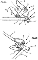
- the Fig. 1a, b show a pressing device 1 in a plan and a side view, as is known in the prior art and as usually for pressing the tubes (in Fig. 1 a, b not shown) is used.
- a pressing device 1 has two pressing jaws 2, 2 ', which are hingedly connected to a connecting plate 3, 3' and a receptacle 5, which receives the parts to be pressed.
- a fastening bolt 4 is provided for the connection, which passes through both the connecting tab 3, 3 'and the pressing jaw 2, 2'.
- the fastening bolt 4, 4 ' protrudes significantly beyond the connecting strap 3, 3', so that the illustrated pressing device 1 has a width B1, which is predetermined by the length of the bolt 4, 4 '.
- Fig. 1c shows by way of example a T-shaped fitting 6 with three nozzles 7, 7 ', 7 “and correspondingly three press sleeves 8, 8', 8". Between the press sleeves 7, 7 ', 7 “and the respective nozzle 8, 8', 8", an annular space is created for receiving a tube 9, 9 ', 9 ", which in the assembled state (see arrow 17) between the compression sleeve 7, 7 ', 7 “and the nozzle 8, 8', 8" is clamped.
- FIG. 2a, b show a typical example of the compression of a T-shaped press fitting 6 (as exemplified in Fig. 1c in which a first pipe 9 "has already been pressed in.
- the compression sleeve 8 In order to produce the pipe 9 (in FIG Fig. 2a not visible), the compression sleeve 8 must be placed in the receptacle 5 of the pressing tool 1.
- Fig. 2a shows the situation in a side view and the lowest possible angle ⁇ , which the attached pressing tool 1 can have with respect to the tube 9 ", due to the width B1 of the pressing device 1 and in particular because of the bolt 4, 4 'of the Tube 9 "blocked.
- the material thickness of the pressing device and its components, in particular the connecting strap and the bolt is essentially predetermined by the required stability.
- a narrower connection tab and / or narrower press jaws can not be used, so possibly a smaller width of the overall device could be achieved.
- a pressing device which according to the invention provides that the connecting plate has at least one bore for receiving the fastening bolt and a cutout engaging around the bore, in which the bolt head of the fastening bolt rests.
- a recess with a part-circular area is arranged on the receiving side facing the tab, the center of which coincides with the center of the receptacle.
- the annular, the bore embracing cutout and on the other hand, the recess with the part-circular area on the receiving side facing the connecting plate can be independently formed on a pressing device according to the invention and both provide the advantage that an unobstructed rotation of the pressing device to an attached compression sleeve is possible.
- the annular and the bore encompassing cutout rests the bolt head of the connecting bolt in a recess, which significantly reduces the width of the pressing device.
- the recess with the part-circular area in turn makes room for an existing compression sleeve of an adjacent nozzle, so that rotation of the pressing device can take place unhindered.
- the stability of the pressing device and the stability of the connecting strap are not affected by the low proportion of milled material, so that the original stability is maintained.
- the pressing device has two connecting straps, between which the pressing jaws are pivotally mounted. Both connecting straps are essentially identical and have the same recesses and cutouts, so that the pressing device is usable on both sides and has no preferential orientation.
- the recess provides space for an adjacent compression sleeve.
- the radius of the recess or the part-circular area is at least the length of a nozzle, preferably 3.5 to 4 cm.
- the recess may also have a deviating from a pitch geometry, as long as the part-circular area with the required radius is completely within the recess.
- the recess and the part-circular area can also be identical.
- the cutout engaging around the hole has a depth which corresponds at least to the height of the bolt head, so that the bolt head does not project beyond the upper edge of the cutout. If the depth of the cut-out is chosen so that it corresponds exactly to the height of the bolt head, a recess with the lowest possible depth is selected, which provides the greatest stability of the connecting plate and is therefore preferred.
- the outer surfaces of two connecting straps of a pressing tool have a distance of 3 to 4 cm, preferably from 3.4 to 3.6 cm. This ensures that the pressing device is adapted to common press fittings and meets the above conditions.
- FIG Fig. 3a A concrete embodiment of a pressing tongs 20 according to the invention with two pressing jaws 2, 2 'and a connecting lug 21 (shown) is shown in FIG Fig. 3a shown.
- the illustrated pressing tool according to the invention 20 has a connecting plate 21 with a part-circular recess 22 and in each case an annular cutout 23, 23 ', in which the bolt heads 24, 24' rest.
- the recess 22 corresponds to the part-circular area.
- the center 25 of the part-circular recess 22 or the center of the part-circular area coincides with the center of the recess 5.
- the radius R of the part-circular recess 22 corresponds at least to the length L of a nozzle, which measures from the center of a fitting 6 and in Fig. 1c is drawn.
- Fig. 3b shows the sectional plane BB and thus a cross-sectional view of the connecting plate 21 with the recess 22, within which the compression sleeve of an adjacent nozzle is freely movable.
- Fig. 3c shows finally a sectional view along the sectional plane AA and thus the annular cutouts 25, 25 ', 25 ", 25”', which surround the respective bores 26, 26 ', 26 “, 26'”.
- the bolt heads 24, 24 ', 24 ", 24”' thus rest in each case in a recess of the connecting plate 21, 21 'and do not protrude beyond their surfaces 27, 27' addition.
- the width B2 of the pressing tool 20 is substantially smaller than the width B1 of a conventional pressing tool 1 according to FIG Fig. 1a because the bolt heads do not protrude beyond the connecting tab 21 '21'. A total width of 3.6 cm is therefore not exceeded.
Landscapes
- Engineering & Computer Science (AREA)
- Mechanical Engineering (AREA)
- Press Drives And Press Lines (AREA)
- Clamps And Clips (AREA)
Abstract
Description
- Die vorliegende Erfindung betrifft eine Pressvorrichtung zum Verpressen eines Rohres mit einem Verbindungsstück (Fitting) mit mindestens zwei Pressbacken, die verschwenkbar mit mindestens einer Verbindungslasche derart verbunden sind, dass sowohl die Verbindungslasche als auch die Pressbacken von jeweils einem Befestigungsbolzen durchgriffen werden, und einer Aufnahme, die die zu verpressenden Teile aufnimmt.
- Derartige Pressvorrichtungen sind nach dem Stand der Technik bereits bekannt und werden hauptsächlich in der Sanitärinstallation eingesetzt, um Rohre und Rohrenden über Verbindungsstücke (Fittinge), insbesondere Pressfittinge, miteinander zu verbinden. Solche Fittinge besitzen mindestens einen rohrförmigen Stutzen, der koaxial und beabstandet von einer Presshülse umfasst ist. Das zu verbindende Rohr wird auf diesen Stutzen aufgesteckt und die Presshülse mit einer geeigneten Pressvorrichtung bzw. mit einem geeigneten Presswerkzeug aufgepresst, um eine unlösbare Verbindung zwischen dem Rohr und dem Fitting zu schaffen. Neben Pressfittingen mit einem oder zwei Stutzen sind auch T-förmige Fittinge mit drei Stutzen und kreuzförmige Fittinge mit vier Stutzen bekannt.
- Die
Fig. 1a, b zeigen eine Pressvorrichtung 1 in einer Drauf- und einer Seitenansicht, wie sie nach dem Stand der Technik bekannt ist und wie sie üblicherweise zum Verpressen der Rohre (inFig. 1 a,b nicht gezeigt) verwendet wird. Eine solche Pressvorrichtung 1 besitzt zwei Pressbacken 2, 2', die gelenkig mit einer Verbindungslasche 3, 3' verbunden sind sowie eine Aufnahme 5, die die zu verpressenden Teile aufnimmt. Üblicherweise ist zur Verbindung ein Befestigungsbolzen 4 vorgesehen, der sowohl die Verbindungslasche 3, 3' als auch die Pressbacke 2, 2' durchgreift. In der Seitenansicht (Fig. 1 b) ist klar zu erkennen, dass der Befestigungsbolzen 4, 4' deutlich über die Verbindungslasche 3, 3' hinausragt, so dass die dargestellte Pressvorrichtung 1 eine Breite B1 aufweist, die von der Länge des Bolzens 4, 4' vorgegeben ist. -
Fig. 1c zeigt beispielhaft ein T-förmiges Fitting 6 mit drei Stutzen 7, 7', 7" und entsprechend drei Presshülsen 8, 8', 8". Zwischen den Presshülsen 7, 7', 7" und dem jeweiligen Stutzen 8, 8', 8" entsteht ein ringförmiger Raum zur Aufnahme eines Rohres 9, 9', 9", das im zusammengesetzten Zustand (s. Pfeil 17) zwischen der Presshülse 7, 7', 7" und dem Stutzen 8, 8', 8" eingeklemmt ist. - Solange genügend Platz zur Positionierung der Pressvorrichtung besteht, ist die Breite B1 der Pressvorrichtung kein Problem. In der Praxis treten allerdings regelmäßig Probleme auf, bei denen der Pressvorgang durch beengte Platzverhältnisse erschwert wird. Die
Fig. 2a, b zeigen ein typisches Beispiel anhand der Verpressung eines T-förmigen Pressfittings 6 (wie es beispielhaft inFig. 1c dargestellt ist), bei dem bereits ein erstes Rohr 9" verpresst ist. Um auch das Rohr 9 (inFig. 2a nicht erkennbar) zu verpressen, muss die Presshülse 8 in die Aufnahme 5 des Presswerkzeugs 1 gelegt werden. Die überwiegend verwendeten Fittinge sind dabei derart kurz ausgestaltet, dass die Verbindungslasche 3, 3' und/oder der Befestigungsbolzen 4, 4' eine ungehinderte Drehung der Pressvorrichtung 1 um die Presshülse 8 verhindert. Demzufolge sind nur wenige Winkelpositionen möglich, mit denen das Presswerkzeug 1 angesetzt werden kann.Fig. 2a zeigt die Situation in einer Seitendarstellung und den geringstmöglichen Winkel α, den das angesetzte Presswerkzeug 1 gegenüber dem Rohr 9" aufweisen kann. Eine weitere Verschwenkung in Pfeilrichtung 10 wird aufgrund der Breite B1 der Pressvorrichtung 1 und insbesondere wegen des Bolzens 4, 4' von dem Rohr 9" blockiert. - Die Materialstärke der Pressvorrichtung und deren Bauteile, insbesondere der Verbindungslasche und der Bolzen ist im Wesentlichen durch die erforderliche Stabilität vorgegeben. Insofern können eine schmalere Verbindungslasche und/oder schmalere Pressbacken nicht eingesetzt werden, womit möglicherweise eine geringere Breite der Gesamtvorrichtung erzielt werden könnte.
- Es ist daher die Aufgabe der vorliegenden Erfindung eine Pressvorrichtung vorzuschlagen, die den Anforderungen an Stabilität genügt und die dennoch die Möglichkeit schafft, beim Verpressen eine beliebige Winkelposition des Presswerkzeugs gegenüber dem Pressfitting, insbesondere gegenüber einem parallel angeordneten Stutzen, einzunehmen.
- Diese Aufgabe wird durch eine Pressvorrichtung nach Anspruch 1 gelöst, die erfindungsgemäß vorsieht, dass die Verbindungslasche mindestens eine Bohrung zur Aufnahme des Befestigungsbolzens und eine die Bohrung umgreifende Ausfräsung aufweist, in der der Bolzenkopf des Befestigungsbolzens ruht. Alternativ oder additiv ist auf der der Aufnahme zugewandten Seite der Lasche eine Ausnehmung mit einem teilkreisförmigen Bereich angeordnet, dessen Mittelpunkt mit dem Mittelpunkt der Aufnahme zusammenfällt.
- Die erfindungsgemäßen Merkmale, nämlich einerseits die ringförmige, die Bohrung umgreifende Ausfräsung und andererseits die Ausnehmung mit dem teilkreisförmigen Bereich auf der der Aufnahme zugewandten Seite der Verbindungslasche können unabhängig voneinander an einer erfindungsgemäßen Pressvorrichtung ausgebildet sein und liefern beide den Vorteil, dass eine ungehinderte Drehung der Pressvorrichtung um eine angesetzte Presshülse möglich ist. Durch die ringförmige und die Bohrung umgreifende Ausfräsung ruht der Bolzenkopf des Verbindungsbolzens in einer Vertiefung, was die Breite der Pressvorrichtung deutlich reduziert. Die Ausnehmung mit dem teilkreisförmigen Bereich wiederrum schafft Platz für eine etwa vorhandene Presshülse eines benachbarten Stutzens, so dass eine Rotation der Pressvorrichtung ungehindert erfolgen kann. Die Stabilität der Pressvorrichtung und die Stabilität der Verbindungslasche werden durch den geringen Anteil des abgefrästen Materials nicht beeinflusst, so dass die ursprüngliche Stabilität erhalten bleibt.
- Weitere bevorzugte Ausgestaltungen der Erfindung werden im Folgenden und in den Unteransprüchen beschrieben.
- Nach einer ersten bevorzugten Ausgestaltung der Erfindung besitzt die Pressvorrichtung zwei Verbindungslaschen, zwischen denen die Pressbacken schwenkbar gelagert sind. Beide Verbindungslaschen sind im Wesentlichen baugleich und weisen die gleichen Ausnehmungen und Ausfräsungen auf, so dass die Pressvorrichtung beidseitig nutzbar ist und keine Vorzugsorientierung aufweist.
- Es wurde bereits erläutert, dass die Ausnehmung Platz für eine benachbarte Presshülse liefert. Vom Mittelpunkt eines T-förmigen Pressfittings aus betrachtet, beträgt der Radius der Ausnehmung oder des teilkreisförmigen Bereiches nach einer bevorzugten Ausgestaltung der Erfindung mindestens die Länge eines Stutzens, vorzugsweise 3,5 bis 4 cm. Es versteht sich von selbst, dass die Ausnehmung auch eine von einem Teilkreis abweichende Geometrie aufweisen kann, solange der teilkreisförmige Bereich mit dem erforderlichen Radius komplett innerhalb der Ausnehmung liegt. Die Ausnehmung und der teilkreisförmige Bereich können auch identisch ausgebildet sein.
- In ähnlicher Weise ist nach einer weiteren bevorzugten Ausgestaltung der Erfindung vorgesehen, dass die die Bohrung umgreifende Ausfräsung eine Tiefe aufweist, die mindestens der Höhe des Bolzenkopfes entspricht, so dass der Bolzenkopf nicht die Oberkante der Ausfräsung überragt. Ist die Tiefe der Ausfräsung derart gewählt, dass sie exakt der Höhe des Bolzenkopfes entspricht, ist eine Ausnehmung mit der geringstmöglichen Tiefe gewählt, was die größte Stabilität der Verbindungslasche liefert und insofern bevorzugt ist.
- Schließlich ist nach einer besonders bevorzugten Ausgestaltung der Erfindung vorgesehen, dass die Außenflächen zweier Verbindungslaschen eines Presswerkzeugs einen Abstand von 3 bis 4 cm, vorzugsweise von 3,4 bis 3,6 cm aufweisen. Hierdurch ist gewährleistet, dass die Pressvorrichtung an gängige Pressfittinge angepasst ist und den vorgenannten Bedingungen genügt.
- Weitere konkrete Ausgestaltungen der Erfindung werden nachfolgend anhand der Figuren erläutert. Es zeigen:
- Fig. 3a
- eine erfindungsgemäße Pressvorrichtung in einer Draufsicht,
- Fig. 3b, c
- Querschnittsdarstellungen der Verbindungslasche und
- Fig. 3d
- eine erfindungsgemäße Pressvorrichtung in einer Seitendarstellung.
- Ein konkretes Ausführungsbeispiel einer erfindungsgemäßen Presszange 20 mit zwei Pressbacken 2, 2' und einer (dargestellten) Verbindungslasche 21 ist in
Fig. 3a gezeigt. In Abgrenzung zu der Presszange 1 gemäßAbbildung 1a besitzt die dargestellte und erfindungsgemäße Presszange 20 eine Verbindungslasche 21 mit einer teilkreisförmigen Ausnehmung 22 und jeweils einer ringförmigen Ausfräsung 23, 23', in denen die Bolzenköpfe 24, 24' ruhen. Im dargestellten Ausführungsbeispiel entspricht die Ausnehmung 22 dem teilkreisförmigen Bereich. Der Mittelpunkt 25 der teilkreisförmigen Ausnehmung 22 beziehungsweise der Mittelpunkt des teilkreisförmigen Bereiches fällt dabei mit dem Mittelpunkt der Ausnehmung 5 zusammen. Der Radius R der teilkreisförmigen Ausnehmung 22 entspricht mindestens der Länge L eines Stutzens, die sich von dem Mittelpunkt eines Fittings 6 misst und inFig. 1c eingezeichnet ist. -
Fig. 3b zeigt die Schnittebene B-B und mithin eine Querschnittsdarstellung der Verbindungslasche 21 mit der Ausnehmung 22, innerhalb der die Presshülse eines benachbarten Stutzens frei beweglich ist. -
Fig. 3c zeigt schließlich eine Schnittansicht entlang der Schnittebene A-A und mithin die ringförmigen Ausfräsungen 25, 25', 25", 25"', die die jeweiligen Bohrungen 26, 26', 26", 26'" umgreifen. Die Bolzenköpfe 24, 24', 24", 24"' ruhen mithin in jeweils einer Vertiefung der Verbindungslasche 21, 21' und ragen nicht über deren Oberflächen 27, 27' hinaus. Aus der Seitenansicht derFig. 3d eines erfindungsgemäßen Presswerkzeugs 20 ergibt sich unmittelbar, dass die Breite B2 des Presswerkzeugs 20 wesentlich geringer ist als die Breite B1 eines herkömmlichen Presswerkzeugs 1 gemäßFig. 1a , weil die Bolzenköpfe nicht über die Verbindungslasche 21 '21' hinaus abstehen. Eine Gesamtbreite von 3,6 cm wird mithin nicht überschritten.
Claims (5)
- Pressvorrichtung zum Verpressen eines Rohres (9, 9',9") mit einem Verbindungsstück (Fitting) (6) mit mindestens zwei Pressbacken (2, 2'), die verschwenkbar mit mindestens einer Verbindungslasche (21, 21') derart verbunden sind, dass sowohl die Verbindungslasche (21, 21') als auch die Pressbacken (2, 2') von jeweils einem Befestigungsbolzen (28, 28') durchgriffen werden, und einer Aufnahme (5), die die zu verpressenden Teile aufnimmt,
dadurch gekennzeichnet, dassa) die Verbindungslasche (21, 21') mindestens eine Bohrung (26, 26', 26", 26'") zur Aufnahme des Befestigungsbolzens (28, 28') und eine die Bohrung (26, 26', 26", 26'") umgreifende Ausfräsung (25, 25', 25", 25'") besitzt, in der der Bolzenkopf (24, 24', 24", 24'") des Befestigungsbolzens (28, 28') ruht, und/oderb) auf der der Aufnahme (5) zugewandten Seite der Verbindungslasche (21, 21') eine Ausnehmung (22) mit einem teilkreisförmigen Bereiches angeordnet ist, dessen Mittelpunkt mit dem Mittelpunkt der Aufnahme (5) zusammenfällt. - Pressvorrichtung nach Anspruch 1, dadurch gekennzeichnet, dass die Pressvorrichtung (20) zwei Verbindungslaschen (21, 21') besitzt, zwischen denen die Pressbacken (2, 2') schwenkbar gelagert sind.
- Pressvorrichtung nach einem der Ansprüche 1 oder 2, dadurch gekennzeichnet, dass der Radius (R) der Ausnehmung (22) oder des teilkreisförmigen Bereiches mindestens der Länge (L) eines Stutzens (7, 7', 7") entspricht, insbesondere 3,5 bis 4 cm.
- Pressvorrichtung nach einem der Ansprüche 1 bis 3, dadurch gekennzeichnet, dass die die Bohrung (26, 26', 26", 26'") umgreifende Ausfräsung (25, 25', 25", 25"') eine Tiefe aufweist, die mindestens der Höhe des Bolzenkopfes (24, 24', 24", 24'") entspricht, so dass der Bolzenkopf (24, 24', 24", 24'") nicht die Oberkante der Ausfräsung (25, 25', 25", 25'") überragt.
- Pressvorrichtung nach einem der Ansprüche 1 bis 4, dadurch gekennzeichnet, dass die Außenflächen (27, 27') zweier Verbindungslaschen (21, 21') eines Presswerkzeugs einen Abstand von 3 bis 4 cm, vorzugsweise von 3,4 bis 3,6 cm aufweisen.
Applications Claiming Priority (1)
| Application Number | Priority Date | Filing Date | Title |
|---|---|---|---|
| DE102016100823.0A DE102016100823A1 (de) | 2016-01-19 | 2016-01-19 | Pressvorrichtung |
Publications (2)
| Publication Number | Publication Date |
|---|---|
| EP3205455A1 true EP3205455A1 (de) | 2017-08-16 |
| EP3205455B1 EP3205455B1 (de) | 2019-06-12 |
Family
ID=57796207
Family Applications (1)
| Application Number | Title | Priority Date | Filing Date |
|---|---|---|---|
| EP17151154.6A Active EP3205455B1 (de) | 2016-01-19 | 2017-01-12 | Pressvorrichtung |
Country Status (2)
| Country | Link |
|---|---|
| EP (1) | EP3205455B1 (de) |
| DE (1) | DE102016100823A1 (de) |
Citations (4)
| Publication number | Priority date | Publication date | Assignee | Title |
|---|---|---|---|---|
| EP0826441A1 (de) * | 1996-08-26 | 1998-03-04 | Franz Viegener II GmbH & Co. KG. | Pressbacke für ein Presswerkzeug für eine unlösbare Kaltverbindung zwischen einem Fitting und einem Metallrohr |
| DE102004016110A1 (de) * | 2004-04-01 | 2005-10-20 | Klauke Gmbh Gustav | Presshebel für ein Verpressgerät sowie Verfahren zur Überprüfung der Vollständigkeit einer Verpressung |
| EP2027971A2 (de) * | 2007-08-24 | 2009-02-25 | REMS-WERK Christian Föll und Söhne GmbH | Presszange zum radialen Verpressen von Rohren, Rohrstücken und dergleichen |
| DE102012100357A1 (de) * | 2012-01-17 | 2013-07-18 | Viega Gmbh & Co. Kg | Lösbare Werkzeugbackenhälfte |
Family Cites Families (4)
| Publication number | Priority date | Publication date | Assignee | Title |
|---|---|---|---|---|
| DE9314054U1 (de) * | 1992-11-10 | 1993-11-25 | Geberit Ag, Jona, St.Gallen | Preßzange zum Verpressen von Rohrverbindungen |
| DE20016060U1 (de) * | 2000-09-16 | 2000-12-28 | Volp, Rainer, 36369 Lautertal | Presszange |
| DE102004005558B4 (de) * | 2004-01-31 | 2006-04-20 | Michael Birk | Presszangenkopf und Presswerkzeug |
| ES2289679T3 (es) * | 2005-05-04 | 2008-02-01 | Wen-Ya Yeh | Dispositivo pivotante para tijeras. |
-
2016
- 2016-01-19 DE DE102016100823.0A patent/DE102016100823A1/de not_active Withdrawn
-
2017
- 2017-01-12 EP EP17151154.6A patent/EP3205455B1/de active Active
Patent Citations (4)
| Publication number | Priority date | Publication date | Assignee | Title |
|---|---|---|---|---|
| EP0826441A1 (de) * | 1996-08-26 | 1998-03-04 | Franz Viegener II GmbH & Co. KG. | Pressbacke für ein Presswerkzeug für eine unlösbare Kaltverbindung zwischen einem Fitting und einem Metallrohr |
| DE102004016110A1 (de) * | 2004-04-01 | 2005-10-20 | Klauke Gmbh Gustav | Presshebel für ein Verpressgerät sowie Verfahren zur Überprüfung der Vollständigkeit einer Verpressung |
| EP2027971A2 (de) * | 2007-08-24 | 2009-02-25 | REMS-WERK Christian Föll und Söhne GmbH | Presszange zum radialen Verpressen von Rohren, Rohrstücken und dergleichen |
| DE102012100357A1 (de) * | 2012-01-17 | 2013-07-18 | Viega Gmbh & Co. Kg | Lösbare Werkzeugbackenhälfte |
Also Published As
| Publication number | Publication date |
|---|---|
| DE102016100823A1 (de) | 2017-07-20 |
| EP3205455B1 (de) | 2019-06-12 |
Similar Documents
| Publication | Publication Date | Title |
|---|---|---|
| DE102014117113A1 (de) | Verbindungsvorrichtung für Gebäudeträger | |
| EP3214403A1 (de) | Haltevorrichtung für ein lasergerät | |
| DE29721146U1 (de) | Verbindungsstück | |
| DE202009004970U1 (de) | Anordnung mit zumindest zwei aneinandergrenzenden Kabeltragvorrichtungselementen | |
| DE3721092C2 (de) | Rohrverbindungssystem | |
| DE4309862A1 (de) | Verbindungseinrichtung für Gitterrinnen | |
| EP3205455B1 (de) | Pressvorrichtung | |
| EP3658787B1 (de) | Formbauteil, verfahren zur verbindung von zumindest einem blechbauteil mit einem formbauteil und system einer blechkonstruktion | |
| DE3436990A1 (de) | Bausatz fuer griffartige, zusammensetzbare beschlaege | |
| DE202020102278U1 (de) | Eckkonsole | |
| DE202016100233U1 (de) | Pressvorrichtung | |
| EP3240103A1 (de) | Masthalter sowie verfahren zum montieren eines masthalters | |
| DE2842925C2 (de) | ||
| DE2142621A1 (de) | Verbindung von rechteckprofilen | |
| DE19921690A1 (de) | Hohlprofilverbindung | |
| EP3716423A1 (de) | Werkzeug zum ausgerichteten montieren von geräteeinsätzen | |
| DE202018006350U1 (de) | Vorrichtung zum abgedichteten Durchführen von Kabeln und/oder Leitungen durch eine Bodenplatte in ein Gebäude | |
| DE3329036A1 (de) | Vorrichtung zum verbinden der enden von unter einem winkel zueinander verlaufenden gittertraegern | |
| EP3239537B1 (de) | Befestigungseinrichtung und verfahren zu deren herstellung | |
| DE363984C (de) | Kupplung fuer Schlaeuche, Rohre, Stangen u. dgl. | |
| DE202017104881U1 (de) | Anschlusselement für einen Erdungsverbinder zum Einbetonieren in ein Betonelement | |
| DE3324337A1 (de) | Befestigungselement zur festlegung von gegenstaenden mit zylindrischer oberflaeche | |
| DE944683C (de) | Verbindung fuer Bau- und andere Gerueste sowie Gestelle aller Art | |
| DE202009009823U1 (de) | Verbindungsklemmelement bzw. Aufnahme für ein Verbindungsklemmelement | |
| DE3708144C2 (de) | Verbindungsanordnung für die Enden von in einem Winkel zueinander verlaufenden Gitterträgern |
Legal Events
| Date | Code | Title | Description |
|---|---|---|---|
| PUAI | Public reference made under article 153(3) epc to a published international application that has entered the european phase |
Free format text: ORIGINAL CODE: 0009012 |
|
| STAA | Information on the status of an ep patent application or granted ep patent |
Free format text: STATUS: THE APPLICATION HAS BEEN PUBLISHED |
|
| AK | Designated contracting states |
Kind code of ref document: A1 Designated state(s): AL AT BE BG CH CY CZ DE DK EE ES FI FR GB GR HR HU IE IS IT LI LT LU LV MC MK MT NL NO PL PT RO RS SE SI SK SM TR |
|
| AX | Request for extension of the european patent |
Extension state: BA ME |
|
| STAA | Information on the status of an ep patent application or granted ep patent |
Free format text: STATUS: REQUEST FOR EXAMINATION WAS MADE |
|
| 17P | Request for examination filed |
Effective date: 20171025 |
|
| RBV | Designated contracting states (corrected) |
Designated state(s): AL AT BE BG CH CY CZ DE DK EE ES FI FR GB GR HR HU IE IS IT LI LT LU LV MC MK MT NL NO PL PT RO RS SE SI SK SM TR |
|
| STAA | Information on the status of an ep patent application or granted ep patent |
Free format text: STATUS: EXAMINATION IS IN PROGRESS |
|
| 17Q | First examination report despatched |
Effective date: 20180823 |
|
| GRAP | Despatch of communication of intention to grant a patent |
Free format text: ORIGINAL CODE: EPIDOSNIGR1 |
|
| STAA | Information on the status of an ep patent application or granted ep patent |
Free format text: STATUS: GRANT OF PATENT IS INTENDED |
|
| INTG | Intention to grant announced |
Effective date: 20190218 |
|
| GRAJ | Information related to disapproval of communication of intention to grant by the applicant or resumption of examination proceedings by the epo deleted |
Free format text: ORIGINAL CODE: EPIDOSDIGR1 |
|
| STAA | Information on the status of an ep patent application or granted ep patent |
Free format text: STATUS: EXAMINATION IS IN PROGRESS |
|
| GRAP | Despatch of communication of intention to grant a patent |
Free format text: ORIGINAL CODE: EPIDOSNIGR1 |
|
| STAA | Information on the status of an ep patent application or granted ep patent |
Free format text: STATUS: GRANT OF PATENT IS INTENDED |
|
| GRAS | Grant fee paid |
Free format text: ORIGINAL CODE: EPIDOSNIGR3 |
|
| INTC | Intention to grant announced (deleted) | ||
| GRAA | (expected) grant |
Free format text: ORIGINAL CODE: 0009210 |
|
| STAA | Information on the status of an ep patent application or granted ep patent |
Free format text: STATUS: THE PATENT HAS BEEN GRANTED |
|
| INTG | Intention to grant announced |
Effective date: 20190423 |
|
| AK | Designated contracting states |
Kind code of ref document: B1 Designated state(s): AL AT BE BG CH CY CZ DE DK EE ES FI FR GB GR HR HU IE IS IT LI LT LU LV MC MK MT NL NO PL PT RO RS SE SI SK SM TR |
|
| REG | Reference to a national code |
Ref country code: GB Ref legal event code: FG4D Free format text: NOT ENGLISH |
|
| REG | Reference to a national code |
Ref country code: CH Ref legal event code: EP |
|
| REG | Reference to a national code |
Ref country code: AT Ref legal event code: REF Ref document number: 1141978 Country of ref document: AT Kind code of ref document: T Effective date: 20190615 |
|
| REG | Reference to a national code |
Ref country code: CH Ref legal event code: NV Representative=s name: RENTSCH PARTNER AG, CH |
|
| REG | Reference to a national code |
Ref country code: DE Ref legal event code: R096 Ref document number: 502017001494 Country of ref document: DE |
|
| REG | Reference to a national code |
Ref country code: IE Ref legal event code: FG4D Free format text: LANGUAGE OF EP DOCUMENT: GERMAN |
|
| REG | Reference to a national code |
Ref country code: NL Ref legal event code: MP Effective date: 20190612 |
|
| REG | Reference to a national code |
Ref country code: LT Ref legal event code: MG4D |
|
| PG25 | Lapsed in a contracting state [announced via postgrant information from national office to epo] |
Ref country code: AL Free format text: LAPSE BECAUSE OF FAILURE TO SUBMIT A TRANSLATION OF THE DESCRIPTION OR TO PAY THE FEE WITHIN THE PRESCRIBED TIME-LIMIT Effective date: 20190612 Ref country code: FI Free format text: LAPSE BECAUSE OF FAILURE TO SUBMIT A TRANSLATION OF THE DESCRIPTION OR TO PAY THE FEE WITHIN THE PRESCRIBED TIME-LIMIT Effective date: 20190612 Ref country code: HR Free format text: LAPSE BECAUSE OF FAILURE TO SUBMIT A TRANSLATION OF THE DESCRIPTION OR TO PAY THE FEE WITHIN THE PRESCRIBED TIME-LIMIT Effective date: 20190612 Ref country code: LT Free format text: LAPSE BECAUSE OF FAILURE TO SUBMIT A TRANSLATION OF THE DESCRIPTION OR TO PAY THE FEE WITHIN THE PRESCRIBED TIME-LIMIT Effective date: 20190612 Ref country code: SE Free format text: LAPSE BECAUSE OF FAILURE TO SUBMIT A TRANSLATION OF THE DESCRIPTION OR TO PAY THE FEE WITHIN THE PRESCRIBED TIME-LIMIT Effective date: 20190612 Ref country code: NO Free format text: LAPSE BECAUSE OF FAILURE TO SUBMIT A TRANSLATION OF THE DESCRIPTION OR TO PAY THE FEE WITHIN THE PRESCRIBED TIME-LIMIT Effective date: 20190912 |
|
| PG25 | Lapsed in a contracting state [announced via postgrant information from national office to epo] |
Ref country code: BG Free format text: LAPSE BECAUSE OF FAILURE TO SUBMIT A TRANSLATION OF THE DESCRIPTION OR TO PAY THE FEE WITHIN THE PRESCRIBED TIME-LIMIT Effective date: 20190912 Ref country code: GR Free format text: LAPSE BECAUSE OF FAILURE TO SUBMIT A TRANSLATION OF THE DESCRIPTION OR TO PAY THE FEE WITHIN THE PRESCRIBED TIME-LIMIT Effective date: 20190913 Ref country code: RS Free format text: LAPSE BECAUSE OF FAILURE TO SUBMIT A TRANSLATION OF THE DESCRIPTION OR TO PAY THE FEE WITHIN THE PRESCRIBED TIME-LIMIT Effective date: 20190612 Ref country code: LV Free format text: LAPSE BECAUSE OF FAILURE TO SUBMIT A TRANSLATION OF THE DESCRIPTION OR TO PAY THE FEE WITHIN THE PRESCRIBED TIME-LIMIT Effective date: 20190612 |
|
| PG25 | Lapsed in a contracting state [announced via postgrant information from national office to epo] |
Ref country code: CZ Free format text: LAPSE BECAUSE OF FAILURE TO SUBMIT A TRANSLATION OF THE DESCRIPTION OR TO PAY THE FEE WITHIN THE PRESCRIBED TIME-LIMIT Effective date: 20190612 Ref country code: PT Free format text: LAPSE BECAUSE OF FAILURE TO SUBMIT A TRANSLATION OF THE DESCRIPTION OR TO PAY THE FEE WITHIN THE PRESCRIBED TIME-LIMIT Effective date: 20191014 Ref country code: RO Free format text: LAPSE BECAUSE OF FAILURE TO SUBMIT A TRANSLATION OF THE DESCRIPTION OR TO PAY THE FEE WITHIN THE PRESCRIBED TIME-LIMIT Effective date: 20190612 Ref country code: NL Free format text: LAPSE BECAUSE OF FAILURE TO SUBMIT A TRANSLATION OF THE DESCRIPTION OR TO PAY THE FEE WITHIN THE PRESCRIBED TIME-LIMIT Effective date: 20190612 Ref country code: EE Free format text: LAPSE BECAUSE OF FAILURE TO SUBMIT A TRANSLATION OF THE DESCRIPTION OR TO PAY THE FEE WITHIN THE PRESCRIBED TIME-LIMIT Effective date: 20190612 Ref country code: SK Free format text: LAPSE BECAUSE OF FAILURE TO SUBMIT A TRANSLATION OF THE DESCRIPTION OR TO PAY THE FEE WITHIN THE PRESCRIBED TIME-LIMIT Effective date: 20190612 |
|
| PG25 | Lapsed in a contracting state [announced via postgrant information from national office to epo] |
Ref country code: IT Free format text: LAPSE BECAUSE OF FAILURE TO SUBMIT A TRANSLATION OF THE DESCRIPTION OR TO PAY THE FEE WITHIN THE PRESCRIBED TIME-LIMIT Effective date: 20190612 Ref country code: SM Free format text: LAPSE BECAUSE OF FAILURE TO SUBMIT A TRANSLATION OF THE DESCRIPTION OR TO PAY THE FEE WITHIN THE PRESCRIBED TIME-LIMIT Effective date: 20190612 Ref country code: IS Free format text: LAPSE BECAUSE OF FAILURE TO SUBMIT A TRANSLATION OF THE DESCRIPTION OR TO PAY THE FEE WITHIN THE PRESCRIBED TIME-LIMIT Effective date: 20191012 Ref country code: ES Free format text: LAPSE BECAUSE OF FAILURE TO SUBMIT A TRANSLATION OF THE DESCRIPTION OR TO PAY THE FEE WITHIN THE PRESCRIBED TIME-LIMIT Effective date: 20190612 |
|
| REG | Reference to a national code |
Ref country code: DE Ref legal event code: R097 Ref document number: 502017001494 Country of ref document: DE |
|
| PG25 | Lapsed in a contracting state [announced via postgrant information from national office to epo] |
Ref country code: TR Free format text: LAPSE BECAUSE OF FAILURE TO SUBMIT A TRANSLATION OF THE DESCRIPTION OR TO PAY THE FEE WITHIN THE PRESCRIBED TIME-LIMIT Effective date: 20190612 |
|
| PLBE | No opposition filed within time limit |
Free format text: ORIGINAL CODE: 0009261 |
|
| STAA | Information on the status of an ep patent application or granted ep patent |
Free format text: STATUS: NO OPPOSITION FILED WITHIN TIME LIMIT |
|
| PG25 | Lapsed in a contracting state [announced via postgrant information from national office to epo] |
Ref country code: DK Free format text: LAPSE BECAUSE OF FAILURE TO SUBMIT A TRANSLATION OF THE DESCRIPTION OR TO PAY THE FEE WITHIN THE PRESCRIBED TIME-LIMIT Effective date: 20190612 Ref country code: PL Free format text: LAPSE BECAUSE OF FAILURE TO SUBMIT A TRANSLATION OF THE DESCRIPTION OR TO PAY THE FEE WITHIN THE PRESCRIBED TIME-LIMIT Effective date: 20190612 |
|
| 26N | No opposition filed |
Effective date: 20200313 |
|
| PG25 | Lapsed in a contracting state [announced via postgrant information from national office to epo] |
Ref country code: SI Free format text: LAPSE BECAUSE OF FAILURE TO SUBMIT A TRANSLATION OF THE DESCRIPTION OR TO PAY THE FEE WITHIN THE PRESCRIBED TIME-LIMIT Effective date: 20190612 Ref country code: IS Free format text: LAPSE BECAUSE OF FAILURE TO SUBMIT A TRANSLATION OF THE DESCRIPTION OR TO PAY THE FEE WITHIN THE PRESCRIBED TIME-LIMIT Effective date: 20200224 |
|
| PG2D | Information on lapse in contracting state deleted |
Ref country code: IS |
|
| PG25 | Lapsed in a contracting state [announced via postgrant information from national office to epo] |
Ref country code: MC Free format text: LAPSE BECAUSE OF FAILURE TO SUBMIT A TRANSLATION OF THE DESCRIPTION OR TO PAY THE FEE WITHIN THE PRESCRIBED TIME-LIMIT Effective date: 20190612 |
|
| REG | Reference to a national code |
Ref country code: BE Ref legal event code: MM Effective date: 20200131 |
|
| PG25 | Lapsed in a contracting state [announced via postgrant information from national office to epo] |
Ref country code: LU Free format text: LAPSE BECAUSE OF NON-PAYMENT OF DUE FEES Effective date: 20200112 |
|
| PG25 | Lapsed in a contracting state [announced via postgrant information from national office to epo] |
Ref country code: BE Free format text: LAPSE BECAUSE OF NON-PAYMENT OF DUE FEES Effective date: 20200131 |
|
| PG25 | Lapsed in a contracting state [announced via postgrant information from national office to epo] |
Ref country code: IE Free format text: LAPSE BECAUSE OF NON-PAYMENT OF DUE FEES Effective date: 20200112 |
|
| PG25 | Lapsed in a contracting state [announced via postgrant information from national office to epo] |
Ref country code: MT Free format text: LAPSE BECAUSE OF FAILURE TO SUBMIT A TRANSLATION OF THE DESCRIPTION OR TO PAY THE FEE WITHIN THE PRESCRIBED TIME-LIMIT Effective date: 20190612 Ref country code: CY Free format text: LAPSE BECAUSE OF FAILURE TO SUBMIT A TRANSLATION OF THE DESCRIPTION OR TO PAY THE FEE WITHIN THE PRESCRIBED TIME-LIMIT Effective date: 20190612 |
|
| PG25 | Lapsed in a contracting state [announced via postgrant information from national office to epo] |
Ref country code: MK Free format text: LAPSE BECAUSE OF FAILURE TO SUBMIT A TRANSLATION OF THE DESCRIPTION OR TO PAY THE FEE WITHIN THE PRESCRIBED TIME-LIMIT Effective date: 20190612 |
|
| REG | Reference to a national code |
Ref country code: AT Ref legal event code: MM01 Ref document number: 1141978 Country of ref document: AT Kind code of ref document: T Effective date: 20220112 |
|
| PG25 | Lapsed in a contracting state [announced via postgrant information from national office to epo] |
Ref country code: AT Free format text: LAPSE BECAUSE OF NON-PAYMENT OF DUE FEES Effective date: 20220112 |
|
| REG | Reference to a national code |
Ref country code: DE Ref legal event code: R082 Ref document number: 502017001494 Country of ref document: DE Representative=s name: RGTH PATENTANWAELTE PARTGMBB, DE Ref country code: DE Ref legal event code: R082 Ref document number: 502017001494 Country of ref document: DE Representative=s name: RGTH RICHTER GERBAULET THIELEMANN HOFMANN PATE, DE |
|
| PGFP | Annual fee paid to national office [announced via postgrant information from national office to epo] |
Ref country code: GB Payment date: 20240119 Year of fee payment: 8 |
|
| GBPC | Gb: european patent ceased through non-payment of renewal fee |
Effective date: 20250112 |
|
| PG25 | Lapsed in a contracting state [announced via postgrant information from national office to epo] |
Ref country code: GB Free format text: LAPSE BECAUSE OF NON-PAYMENT OF DUE FEES Effective date: 20250112 |
|
| REG | Reference to a national code |
Ref country code: CH Ref legal event code: U11 Free format text: ST27 STATUS EVENT CODE: U-0-0-U10-U11 (AS PROVIDED BY THE NATIONAL OFFICE) Effective date: 20260201 |
|
| PGFP | Annual fee paid to national office [announced via postgrant information from national office to epo] |
Ref country code: DE Payment date: 20260122 Year of fee payment: 10 |
|
| PGFP | Annual fee paid to national office [announced via postgrant information from national office to epo] |
Ref country code: FR Payment date: 20260121 Year of fee payment: 10 |
|
| PGFP | Annual fee paid to national office [announced via postgrant information from national office to epo] |
Ref country code: CH Payment date: 20260201 Year of fee payment: 10 |