EP3205463A1 - Broche porte-outil d'usinage du bois, machine à moulurer comprenant une telle broche porte-outil et procédé faisant appel à une broche porte-outil - Google Patents
Broche porte-outil d'usinage du bois, machine à moulurer comprenant une telle broche porte-outil et procédé faisant appel à une broche porte-outil Download PDFInfo
- Publication number
- EP3205463A1 EP3205463A1 EP17000117.6A EP17000117A EP3205463A1 EP 3205463 A1 EP3205463 A1 EP 3205463A1 EP 17000117 A EP17000117 A EP 17000117A EP 3205463 A1 EP3205463 A1 EP 3205463A1
- Authority
- EP
- European Patent Office
- Prior art keywords
- temperature
- spindle
- tool spindle
- temperature sensor
- signals
- Prior art date
- Legal status (The legal status is an assumption and is not a legal conclusion. Google has not performed a legal analysis and makes no representation as to the accuracy of the status listed.)
- Granted
Links
Images


Classifications
-
- B—PERFORMING OPERATIONS; TRANSPORTING
- B27—WORKING OR PRESERVING WOOD OR SIMILAR MATERIAL; NAILING OR STAPLING MACHINES IN GENERAL
- B27C—PLANING, DRILLING, MILLING, TURNING OR UNIVERSAL MACHINES FOR WOOD OR SIMILAR MATERIAL
- B27C5/00—Machines designed for producing special profiles or shaped work, e.g. by rotary cutters; Equipment therefor
- B27C5/10—Portable hand-operated wood-milling machines; Routers
-
- G—PHYSICS
- G01—MEASURING; TESTING
- G01M—TESTING STATIC OR DYNAMIC BALANCE OF MACHINES OR STRUCTURES; TESTING OF STRUCTURES OR APPARATUS, NOT OTHERWISE PROVIDED FOR
- G01M13/00—Testing of machine parts
- G01M13/04—Bearings
-
- B—PERFORMING OPERATIONS; TRANSPORTING
- B23—MACHINE TOOLS; METAL-WORKING NOT OTHERWISE PROVIDED FOR
- B23Q—DETAILS, COMPONENTS, OR ACCESSORIES FOR MACHINE TOOLS, e.g. ARRANGEMENTS FOR COPYING OR CONTROLLING; MACHINE TOOLS IN GENERAL CHARACTERISED BY THE CONSTRUCTION OF PARTICULAR DETAILS OR COMPONENTS; COMBINATIONS OR ASSOCIATIONS OF METAL-WORKING MACHINES, NOT DIRECTED TO A PARTICULAR RESULT
- B23Q17/00—Arrangements for observing, indicating or measuring on machine tools
-
- B—PERFORMING OPERATIONS; TRANSPORTING
- B23—MACHINE TOOLS; METAL-WORKING NOT OTHERWISE PROVIDED FOR
- B23Q—DETAILS, COMPONENTS, OR ACCESSORIES FOR MACHINE TOOLS, e.g. ARRANGEMENTS FOR COPYING OR CONTROLLING; MACHINE TOOLS IN GENERAL CHARACTERISED BY THE CONSTRUCTION OF PARTICULAR DETAILS OR COMPONENTS; COMBINATIONS OR ASSOCIATIONS OF METAL-WORKING MACHINES, NOT DIRECTED TO A PARTICULAR RESULT
- B23Q1/00—Members which are comprised in the general build-up of a form of machine, particularly relatively large fixed members
- B23Q1/70—Stationary or movable members for carrying working-spindles for attachment of tools or work
-
- B—PERFORMING OPERATIONS; TRANSPORTING
- B23—MACHINE TOOLS; METAL-WORKING NOT OTHERWISE PROVIDED FOR
- B23Q—DETAILS, COMPONENTS, OR ACCESSORIES FOR MACHINE TOOLS, e.g. ARRANGEMENTS FOR COPYING OR CONTROLLING; MACHINE TOOLS IN GENERAL CHARACTERISED BY THE CONSTRUCTION OF PARTICULAR DETAILS OR COMPONENTS; COMBINATIONS OR ASSOCIATIONS OF METAL-WORKING MACHINES, NOT DIRECTED TO A PARTICULAR RESULT
- B23Q17/00—Arrangements for observing, indicating or measuring on machine tools
- B23Q17/09—Arrangements for observing, indicating or measuring on machine tools for indicating or measuring cutting pressure or for determining cutting-tool condition, e.g. cutting ability, load on tool
- B23Q17/0952—Arrangements for observing, indicating or measuring on machine tools for indicating or measuring cutting pressure or for determining cutting-tool condition, e.g. cutting ability, load on tool during machining
- B23Q17/0985—Arrangements for observing, indicating or measuring on machine tools for indicating or measuring cutting pressure or for determining cutting-tool condition, e.g. cutting ability, load on tool during machining by measuring temperature
-
- B—PERFORMING OPERATIONS; TRANSPORTING
- B27—WORKING OR PRESERVING WOOD OR SIMILAR MATERIAL; NAILING OR STAPLING MACHINES IN GENERAL
- B27C—PLANING, DRILLING, MILLING, TURNING OR UNIVERSAL MACHINES FOR WOOD OR SIMILAR MATERIAL
- B27C1/00—Machines for producing flat surfaces, e.g. by rotary cutters; Equipment therefor
- B27C1/08—Machines for working several sides of work simultaneously
-
- B—PERFORMING OPERATIONS; TRANSPORTING
- B27—WORKING OR PRESERVING WOOD OR SIMILAR MATERIAL; NAILING OR STAPLING MACHINES IN GENERAL
- B27C—PLANING, DRILLING, MILLING, TURNING OR UNIVERSAL MACHINES FOR WOOD OR SIMILAR MATERIAL
- B27C9/00—Multi-purpose machines; Universal machines; Equipment therefor
- B27C9/04—Multi-purpose machines; Universal machines; Equipment therefor with a plurality of working spindles
-
- B—PERFORMING OPERATIONS; TRANSPORTING
- B27—WORKING OR PRESERVING WOOD OR SIMILAR MATERIAL; NAILING OR STAPLING MACHINES IN GENERAL
- B27G—ACCESSORY MACHINES OR APPARATUS FOR WORKING WOOD OR SIMILAR MATERIALS; TOOLS FOR WORKING WOOD OR SIMILAR MATERIALS; SAFETY DEVICES FOR WOOD WORKING MACHINES OR TOOLS
- B27G21/00—Safety guards or devices specially designed for other wood-working machines auxiliary devices facilitating proper operation of said wood-working machines
-
- F—MECHANICAL ENGINEERING; LIGHTING; HEATING; WEAPONS; BLASTING
- F16—ENGINEERING ELEMENTS AND UNITS; GENERAL MEASURES FOR PRODUCING AND MAINTAINING EFFECTIVE FUNCTIONING OF MACHINES OR INSTALLATIONS; THERMAL INSULATION IN GENERAL
- F16C—SHAFTS; FLEXIBLE SHAFTS; ELEMENTS OR CRANKSHAFT MECHANISMS; ROTARY BODIES OTHER THAN GEARING ELEMENTS; BEARINGS
- F16C41/00—Other accessories, e.g. devices integrated in the bearing not relating to the bearing function as such
-
- F—MECHANICAL ENGINEERING; LIGHTING; HEATING; WEAPONS; BLASTING
- F16—ENGINEERING ELEMENTS AND UNITS; GENERAL MEASURES FOR PRODUCING AND MAINTAINING EFFECTIVE FUNCTIONING OF MACHINES OR INSTALLATIONS; THERMAL INSULATION IN GENERAL
- F16C—SHAFTS; FLEXIBLE SHAFTS; ELEMENTS OR CRANKSHAFT MECHANISMS; ROTARY BODIES OTHER THAN GEARING ELEMENTS; BEARINGS
- F16C2233/00—Monitoring condition, e.g. temperature, load, vibration
-
- F—MECHANICAL ENGINEERING; LIGHTING; HEATING; WEAPONS; BLASTING
- F16—ENGINEERING ELEMENTS AND UNITS; GENERAL MEASURES FOR PRODUCING AND MAINTAINING EFFECTIVE FUNCTIONING OF MACHINES OR INSTALLATIONS; THERMAL INSULATION IN GENERAL
- F16C—SHAFTS; FLEXIBLE SHAFTS; ELEMENTS OR CRANKSHAFT MECHANISMS; ROTARY BODIES OTHER THAN GEARING ELEMENTS; BEARINGS
- F16C2322/00—Apparatus used in shaping articles
- F16C2322/39—General buildup of machine tools, e.g. spindles, slides, actuators
Definitions
- the invention relates to a woodworking tool spindle according to the preamble of claim 1, a molding machine according to claim 8 and a method according to claim 10.
- tool spindles In woodworking machines, especially moulders, tool spindles are used, with which tools required for machining are rotatably driven.
- the tool spindles have a spindle shaft rotatably mounted in a spindle housing.
- the pivot bearings which support the spindle shaft in the spindle housing, partially exposed to high forces. This can cause the pivot bearings to be damaged. Failure to detect a damaged pivot will result in the failure of the corresponding tool spindle, requiring longer machine downtime and high repair costs. Under certain circumstances, a damaged pivot bearing also environmental parts within the machine affected, possibly even damaged.
- the invention is based on the object, the generic tool spindle, the molding machine and the method in such a way that early threatening failure of the tool spindle can be detected in the woodworking machine.
- the tool spindle according to the invention has at least one temperature sensor with which the temperature of the rotary bearing can be detected. This makes it possible to reliably determine whether the temperature of the rotary bearing approaches a critical value during operation of the tool spindle.
- the temperature sensor generates signals which are fed to an evaluation unit, which evaluates the temperature signals accordingly and generates output signals as a function of this evaluation. Due to the temperature monitoring, the user receives an indication in good time before a tool spindle failure that further use of the tool spindle may be critical.
- the temperature sensor may be arranged in the spindle housing adjacent to the rotary bearing. It is thereby possible to bring the temperature sensor very close to the pivot bearing to be monitored. Here, the distance between the temperature sensor and the pivot bearing to be monitored can be very small, so that the temperature of the pivot bearing can be detected properly.
- the spindle housing is provided with at least one axial bore, which opens into an end face of the spindle housing and serves to receive the temperature sensor.
- the temperature sensor can be pushed from the front side of the spindle housing very easy so far into the axial bore until a sensor head or temperature sensor of the sensor is adjacent to the pivot bearing.
- the axial course of the bore in the spindle housing has the advantage that adjusting movements of the spindle axis, in particular of the spindle housing, are not impaired in the axial direction and also transversely thereto when the sensor signals are transmitted via lines. Inside the hole, the sensor is housed protected and does not interfere with the adjustment of the tool spindle.
- the spindle housing has at least one approximately radially extending bore, which opens into the outside of the spindle housing.
- a bore can be very easily attached to the spindle housing. If the temperature sensor is equipped with a sensor cable, it can be routed outwards by the shortest route.
- a particularly advantageous embodiment results when the temperature sensor is arranged directly on or in the rotary bearing, preferably on or in the outer, stationary bearing ring. Then the temperature of the pivot bearing is detected with high accuracy.
- the tool spindle has a plurality of rotary bearings, for example two rotary bearings, then in each case at least one temperature sensor is advantageously provided for each rotary bearing.
- at least one temperature sensor is advantageously provided for each rotary bearing.
- the signals of the temperature sensor can be transmitted either via at least one sensor line or wirelessly.
- the wireless transmission of the sensor signals has the advantage that the laying of sensor lines in the tool spindle and possibly the forwarding to the evaluation unit within the woodworking machine accounts.
- the signals of the temperature sensor are advantageously transmitted to a control of the molding machine.
- This control of the molding machine forms the evaluation unit, which evaluates the signals sent by the temperature sensor.
- At least one of the tool spindles is designed in the manner according to the invention.
- all tool spindles of the molding machine with at least the one Temperature sensor equipped with which the temperature of the pivot bearing of these tool spindles can be detected.
- the user of the molding machine thus reliably receives a status report on all the tool spindles of the molding machine, so that he is informed early if one or more of the tool spindles threaten to fail.
- the molding machine according to the invention advantageously has at least one further sensor which determines the internal temperature of the molding machine, i. H. the ambient temperature of the tool spindle in the moulder detected.
- the signals of this further temperature sensor are used to compensate for the temperature limit of the pivot bearing. If, for example, the ambient temperature in the molding machine increases, the pivot bearing also heats up, without this being due to excessive stress on the pivot bearing. Accordingly, the temperature limit is raised accordingly taking into account the measured ambient temperature, whereby the influence of the ambient temperature is compensated for the temperature of the pivot bearing. The compensation can also be made directly to the temperature signals of the individual sensors.
- the temperature of the rotary bearing with the at least one temperature sensor is constantly detected and fed to the evaluation unit. It compares the supplied sensor signals with the temperature limit. If it is reached, the evaluation unit generates a corresponding signal.
- This signal generated by the evaluation unit can be a warning signal, which indicates to the user that the detected tool spindle has reached a critical range.
- the warning signal can be an audible and / or optical signal or, for example, a warning message on a screen and the like.
- the signal generated by the evaluation unit can also be a shutdown signal, via which machine functions, such as spindle, feed, are switched off.
- machine functions such as spindle, feed
- all spindles and the feed of the molding machine are automatically switched off on the basis of the evaluated temperature signals.
- the evaluation unit can advantageously generate a warning signal. If no measures are initiated by the user, then the evaluation unit generates when reaching the higher temperature limit another signal, which is advantageous in this case a shutdown signal, with the monitored tool spindle or other machine functions are turned off.
- not only the temperature of the pivot bearing but also the ambient temperature of the monitored tool spindle is advantageously detected by at least one further temperature sensor. This ambient temperature is then used to compensate for the temperature limit of the pivot bearing and / or the temperature value.
- the temperature signals of the temperature sensor and / or the further temperature sensor are stored in at least one memory.
- This memory may be a separate memory associated with the woodworking machine.
- the signals can also be stored on a network server or for example in a cloud storage.
- the storage of the signals has the advantage that a service or else the user can see a history of the temperature profile of the pivot bearing at any time.
- the data are stored in such a way that they can be retrieved using a smart device.
- a signal is sent to a service, which can then take appropriate action to check, for example, the causes of the temperature increase of the pivot bearing or schedule the preventive maintenance and to initiate in the way.
- Fig. 1 shows a schematic representation of a moulder, with which in cross-section rectangular workpieces 1 made of wood, plastic and the like can be processed on all four sides in a continuous process.
- Fig. 1 only the spindles and the sitting thereon, schematically illustrated tools are given, with which the workpiece machining takes place.
- the transport elements, supports for the workpieces and the like are not shown for clarity.
- the workpieces 1 are transported in the direction of arrow 2 through the molding machine. First, the underside of the workpieces 1 is processed with a tool 3, which sits on a horizontal spindle 4. With the tool 3, the workpiece 1, for example, planed straight.
- a vertical right spindle 5 which carries a tool 6, with which the right in the direction of passage 2 longitudinal side of the workpiece 1 is processed during the passage of the workpiece.
- a left vertical spindle 7 on which a tool 8 is seated, with which the left in the direction of transport 2 longitudinal side of the workpiece 1 is processed.
- an upper and a lower horizontal spindle 9, 10 are provided, the tools 11, 12 edit the top and bottom of the workpiece 1.
- the tools can each be planing or profiling tools, with which the respective sides are either planed straight or provided with a profile.
- the bearings are monitored by temperature sensors whose signals are fed to a controller 13. These signals can be transmitted via lines 14, but also wirelessly to the controller 13 of the molding machine.
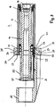
- the spindle 4 has a spindle housing 15 in which a spindle shaft 16 is rotatably mounted.
- the spindle housing 15 is an example of a cylindrical spindle sleeve which surrounds the spindle shaft 16 at a distance.
- pivot bearings 17, 18 are advantageous rolling bearings, in the exemplary embodiment ball bearings.
- two ball bearings are provided adjoining each other at both ends of the spindle housing 15.
- the pivot bearings 17, 18 are axially secured in a suitable manner in the spindle housing 15.
- the spindle 4 is received with the spindle housing 15 in a bore of a spindle slide, not shown, and can be adjusted axially in this bore in a known manner. This can be referred to as quill adjustment.
- the spindle shaft 16 is provided at its one end with a receptacle 19, which is an HSK receptacle in the embodiment, which receives a tool.
- a drive pulley 20 which is a toothed belt pulley in the embodiment over which an endless belt of a drive is guided, with which the spindle shaft 16 is rotatably driven.
- the drive pulley 20 is non-rotatably mounted on the spindle shaft 16 and is secured axially between two rings 21, 22 fastened on the spindle shaft 16.
- the ring 21 is formed as a nut and is used together with the drive pulley 20 and the ring 22 for axial securing of the pivot bearing 17th
- a holder 23 is attached on the spindle 4. He has a receiving ring 24 which is provided at one end face with a recess 25 into which the spindle housing 15 projects with one end.
- the recess 25 is bounded axially by a radially inwardly directed annular flange 26 against which the spindle housing 15 abuts with its frontal edge.
- the receiving ring 25 has on its other end face on a further recess 27, which is substantially flatter than the recess 25 and 23 results due to a machining of the cast holder.
- the soil 28 processed in this way ( Fig. 2 ) is penetrated by fastening screws 29, which are arranged distributed over the circumference of the recess 27 and screwed into threaded bores on the end face of the spindle housing 15.
- the annular flange 26 and the adjacent region of the spindle housing 15 have approximately the same inner diameter.
- the ring 22 has a radially outwardly directed annular flange 30, which has only a small distance to the inside of the annular flange 26 and to the inside of the spindle housing 15 and thus forms a sealing gap. As a result, the penetration of chips or dust to the pivot bearing 17 is prevented.
- a support arm 31 from which is provided at the free end with a retaining ring 32 in which a (not shown) release unit for the clamped in the spindle 4 tools 3 is held.
- the holder 23 serves not only for holding the release unit, but also as a carrier of a nut or a thread for the axial adjustment of the spindle.
- the spindle 4 is provided with temperature sensors 33, 34, with which the temperature of the pivot bearings 17, 18 can be detected.
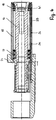
- the temperature sensors 33, 34 by axial bores 35, 36 (FIG. Fig. 3 and 4 ) in the spindle housing 15 to the respective bearings 17, 18 out.
- the sensors have a sensor head 40, 41, the actual temperature sensor, which is inserted in the front end of a thin tube 37, 38, in which sensor lines (sensor wires) 14 are led to the outside.
- To the tube 37, 38 includes a sleeve 44, 45 at ( Fig. 2 ),
- a ferrule from which the tube 37, 38 pickwand end the sheathed flexible sensor lines 14 exit.
- the axial bores 35, 36 extend from the end face of the spindle housing 15 lying in the receiving ring 24.
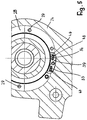
- the temperature sensors 33, 34 protrude with their tube 37, 38 through a mounting block 39 from the spindle housing 15.
- the mounting block 39 is releasably secured to the spindle housing 15.
- the annular flange 26 of the receiving ring 24 is interrupted in the region of the mounting block 39 by a recess 46 ( Fig. 5 ).
- the edges of the recess 46 each have a distance from the mounting block 39.
- the tubes 37, 38 and thus the temperature sensors 33, 34 secured so that they can not be moved in the holes 35, 36. This ensures that the sensor head 40, 41 is always at the level of the pivot bearing 17, 18 to be monitored.
- the backup can be done as in the embodiment of laterally screwed into the mounting block 39 threaded pins 47, 48. As a result, length tolerances or different depth holes 35, 36 can be compensated. It is also possible to provide the sensors 33, 34 with a thread and screw them into the mounting block 39.
- the sensor lines 14 are guided in a suitable manner to the machine control 13, as exemplified by the Fig. 1 has been described and explained with the lines 14. In the illustrated embodiment, the sensor lines 14 are continued through openings 42 in the support arm 31.
- the temperature sensors 33, 34 may also be different from the illustrated embodiment radially to the monitored pivot bearing 17, 18 are introduced. In this case, only very short holes for the temperature sensors 33, 34 are required.
- the temperature of the pivot bearings 17, 18 are permanently monitored.
- the signals of the temperature sensors 33, 34 are fed to an evaluation unit. In the simplest case, when a predetermined temperature limit value is exceeded by the evaluation unit generates a signal. It can be used to send a warning to the user of the spindle or moulder. It is also possible to use this signal to switch off the corresponding machine function, for example the rotary drive of the spindle 4 or the feed, ie the workpiece transport through the molding machine.
- This limit value for the temperature of the rotary bearings 17, 18 can be set so low that the correspondingly evaluated signal of the temperature sensors 33, 34 is emitted early when the pivot bearings 17, 18 are not damaged.
- the temperature sensors 33, 34 are used in this case, the preventive maintenance and the early detection of bearing damage. This reliably prevents consequential damage to the spindle or the moulder due to bearing damage that is not detected in good time.
- the controller 13 may be arranged so that it then shuts off the spindles 4, 5, 7, 9, 10 and the feed to prevent consequential damage.
- the sensor signals are transmitted via the sensor lines 14 to the machine controller 13.
- the sensors can in particular be installed directly on or in the pivot bearings 17, 18, so that the temperature of the pivot bearings 17, 18 can be detected much more accurately.
- the temperature sensors 33, 34 can transmit their signals, for example via radio, for example, to receiving units, which are arranged in the region of the individual spindles.
- the receiving units for the wireless transmission of the sensor signals are in turn connected via lines 14 to the controller 13.
- Such sensors facilitate installation in the spindle 4, because no longer provisions for the implementation of sensor lines are required.
- the sensors 33, 34 transmit their signals via the sensor lines 14, the sensors can be arranged directly in the rotary bearing 17, 18.
- the reliability of the bearing diagnosis or the detection of a bearing damage can be improved in an advantageous manner that the ambient temperature of the spindle 4 is measured.
- at least one further temperature sensor 43 is provided, which is connected to the machine control or evaluation unit 13.
- This sensor 43 can also transmit its signals via sensor lines or wirelessly, for example by radio.
- the controller 13 can be designed such that the limit values of the storage temperatures or the recorded storage temperature values automatically adjusted to the measured interior temperature. If, for example, the interior temperature of the machine detected by the temperature sensor 43 increases, the temperature of the rotary bearings 17, 18 also increases. However, this temperature increase has nothing to do with a corresponding load on the rotary bearings. Accordingly, the control or the evaluation of the temperature sensors is provided so that the corresponding limits are increased so that the influence of the internal temperature of the machine is compensated for the temperature of the rotary bearings 17, 18.
- controller 13 or evaluation unit may be designed such that it does not automatically compensate or adapt the temperature limit values of the rotary bearings 17, 18, but the spindle temperature values as a function of the internal temperature of the machine, for example by an internal temperature-dependent correction value of the measured Temperature value subtracted or added to this. A combination of both methods is possible.
- the automatic adjustment and compensation has the advantage that the user of the machine does not have to make the adjustment itself.
- controller 13 it is quite possible to design the controller 13 so that the limit values for the storage temperatures are adjusted manually as a function of the measured interior temperature of the machine.
- the temperature monitoring of the rotary bearings 17, 18 can be designed so that the temperature values are stored continuously. This makes it possible to record the history of the temperature profile of the individual temperature sensors 33, 34 and, for example, to check the frequency of exceeding the limit values over a certain period of time.
- These stored data can be stored, for example, in the evaluation unit, the machine control or by transmission in a cloud, so that authorized persons at any time stored the Retrieve and evaluate measurements. This is particularly advantageous for the service.
- the storage in a cloud offers the possibility of advantageous use of so-called smart devices and apps for analyzing and displaying certain data from machine-independent locations.
- pivot bearings 17, 18 are monitored separately, their condition can be monitored independently of each other.
- the signals of the temperature sensors 33, 34 are fed to one or more evaluation units as described. These may be part of the machine control or be provided as a unit or units independent of this. In the latter case, the evaluation unit can switch off the machine functions described directly and send the machine control a signal to display a warning or error message.
- the respective current temperatures can be called directly on the screen of the machine control and those temperatures, which exceed the set limit values, are marked, for example, in color, written in color, flashing or the like. It is equally advantageous if the operator receives a message via the machine control, as a result of which limit value violation at which bearing of which spindle the machine (spindles and feed) was switched off.
Landscapes
- Engineering & Computer Science (AREA)
- Life Sciences & Earth Sciences (AREA)
- Mechanical Engineering (AREA)
- Wood Science & Technology (AREA)
- Forests & Forestry (AREA)
- General Engineering & Computer Science (AREA)
- Physics & Mathematics (AREA)
- General Physics & Mathematics (AREA)
- Machine Tool Sensing Apparatuses (AREA)
- Rolling Contact Bearings (AREA)
Priority Applications (1)
| Application Number | Priority Date | Filing Date | Title |
|---|---|---|---|
| SI201730642T SI3205463T1 (sl) | 2016-02-10 | 2017-01-24 | Vreteno za orodje za obdelavo lesa, oblikovalni stroj s takim vretenom za orodje in postopek z uporabo vretena za orodje |
Applications Claiming Priority (1)
| Application Number | Priority Date | Filing Date | Title |
|---|---|---|---|
| DE102016001745.7A DE102016001745B4 (de) | 2016-02-10 | 2016-02-10 | Holzbearbeitungs-Werkzeugspindel und Kehlmaschine mit einer solchen Werkzeugspindel |
Publications (2)
| Publication Number | Publication Date |
|---|---|
| EP3205463A1 true EP3205463A1 (fr) | 2017-08-16 |
| EP3205463B1 EP3205463B1 (fr) | 2020-11-18 |
Family
ID=57956064
Family Applications (1)
| Application Number | Title | Priority Date | Filing Date |
|---|---|---|---|
| EP17000117.6A Active EP3205463B1 (fr) | 2016-02-10 | 2017-01-24 | Broche porte-outil d'usinage du bois, machine à moulurer comprenant une telle broche porte-outil et procédé faisant appel à une broche porte-outil |
Country Status (6)
| Country | Link |
|---|---|
| US (1) | US10466140B2 (fr) |
| EP (1) | EP3205463B1 (fr) |
| CN (1) | CN107052902B (fr) |
| DE (1) | DE102016001745B4 (fr) |
| SI (1) | SI3205463T1 (fr) |
| TW (1) | TWI711519B (fr) |
Cited By (1)
| Publication number | Priority date | Publication date | Assignee | Title |
|---|---|---|---|---|
| EP3403783B1 (fr) * | 2017-05-20 | 2025-09-10 | Michael Weinig AG | Dispositif de surveillance de température pour broches d'outil de machines de traitement du bois ainsi que procédé faisant appel au dispositif de surveillance de la température |
Families Citing this family (2)
| Publication number | Priority date | Publication date | Assignee | Title |
|---|---|---|---|---|
| DE102019112877A1 (de) * | 2019-05-16 | 2020-11-19 | Homag Gmbh | Verfahren zur Überwachung eines Spindellagers |
| CN110160770B (zh) * | 2019-06-25 | 2021-12-21 | 沈阳工业大学 | 高速旋转主轴实时检测装置及其检测方法 |
Citations (5)
| Publication number | Priority date | Publication date | Assignee | Title |
|---|---|---|---|---|
| GB2190876A (en) * | 1986-05-27 | 1987-12-02 | Wadkin Public Ltd Co | Woodworking router |
| EP1579951A1 (fr) * | 2004-03-22 | 2005-09-28 | Paul Müller GmbH & Co. KG Unternehmensbeteiligungen | Broche pour machine-outil avec un roulement pourvu d'un conduit capilaire pour l'alimentation en lubrifiant |
| EP1762331A1 (fr) * | 2005-09-12 | 2007-03-14 | Paul Müller GmbH & Co. KG Unternehmensbeteiligungen | Broche avec capteur de données lisible par ondes radio |
| DE102010003338A1 (de) * | 2010-03-26 | 2011-09-29 | Komet Group Gmbh | Werkzeugmaschine mit Drehübertrager für Daten |
| US20140166323A1 (en) * | 2012-09-16 | 2014-06-19 | J. Carl Cooper | Kickback Reduction for Power Tools and Machines |
Family Cites Families (13)
| Publication number | Priority date | Publication date | Assignee | Title |
|---|---|---|---|---|
| JPH081606A (ja) * | 1994-06-16 | 1996-01-09 | Iida Kogyo Kk | 木材加工機の診断装置 |
| JP3389417B2 (ja) * | 1996-05-29 | 2003-03-24 | 大阪機工株式会社 | ロストモーションの補正方法 |
| US6508614B1 (en) * | 1999-03-17 | 2003-01-21 | Ntn Corporation | Spindle device and machine tool utilizing the same |
| US6505972B1 (en) * | 2000-09-01 | 2003-01-14 | The Timken Company | Bearing with adjustable setting |
| DE10348608B4 (de) * | 2003-10-20 | 2016-05-19 | Siemens Aktiengesellschaft | Überwachungssystem und Verfahren für eine Spindel |
| DE102004050270B4 (de) * | 2004-10-14 | 2008-07-03 | Grotefeld Gmbh | Bearbeitungsaggregat |
| EP2391488A4 (fr) * | 2009-01-30 | 2015-05-13 | René St Cyr 1996 Inc | Fabrication de profils à languette et rainure sur des lames de parquet en bois dur |
| CN102632283B (zh) * | 2012-04-28 | 2013-08-14 | 翟泉来 | 数控钢板双面双边同步坡口直线削边成型机 |
| CN203051516U (zh) * | 2012-12-18 | 2013-07-10 | 广西盛誉糖机制造有限责任公司 | 连续离心分蜜机轴承座组合 |
| JP5902767B2 (ja) * | 2014-07-09 | 2016-04-13 | ファナック株式会社 | モータの過熱推定を行う工作機械の制御装置 |
| US10245697B2 (en) * | 2014-10-29 | 2019-04-02 | Okuma Corporation | Method for controlling temperature adjustment system of machine |
| CN104525980B (zh) * | 2014-11-26 | 2017-02-22 | 北京航天三发高科技有限公司 | 超高速高精度大功率的电主轴 |
| US10371297B2 (en) * | 2016-02-01 | 2019-08-06 | Deublin Company | Rotary union with bellows seal |
-
2016
- 2016-02-10 DE DE102016001745.7A patent/DE102016001745B4/de not_active Expired - Fee Related
-
2017
- 2017-01-24 EP EP17000117.6A patent/EP3205463B1/fr active Active
- 2017-01-24 SI SI201730642T patent/SI3205463T1/sl unknown
- 2017-02-07 TW TW106103950A patent/TWI711519B/zh active
- 2017-02-10 CN CN201710072286.8A patent/CN107052902B/zh active Active
- 2017-02-10 US US15/429,200 patent/US10466140B2/en active Active
Patent Citations (5)
| Publication number | Priority date | Publication date | Assignee | Title |
|---|---|---|---|---|
| GB2190876A (en) * | 1986-05-27 | 1987-12-02 | Wadkin Public Ltd Co | Woodworking router |
| EP1579951A1 (fr) * | 2004-03-22 | 2005-09-28 | Paul Müller GmbH & Co. KG Unternehmensbeteiligungen | Broche pour machine-outil avec un roulement pourvu d'un conduit capilaire pour l'alimentation en lubrifiant |
| EP1762331A1 (fr) * | 2005-09-12 | 2007-03-14 | Paul Müller GmbH & Co. KG Unternehmensbeteiligungen | Broche avec capteur de données lisible par ondes radio |
| DE102010003338A1 (de) * | 2010-03-26 | 2011-09-29 | Komet Group Gmbh | Werkzeugmaschine mit Drehübertrager für Daten |
| US20140166323A1 (en) * | 2012-09-16 | 2014-06-19 | J. Carl Cooper | Kickback Reduction for Power Tools and Machines |
Cited By (1)
| Publication number | Priority date | Publication date | Assignee | Title |
|---|---|---|---|---|
| EP3403783B1 (fr) * | 2017-05-20 | 2025-09-10 | Michael Weinig AG | Dispositif de surveillance de température pour broches d'outil de machines de traitement du bois ainsi que procédé faisant appel au dispositif de surveillance de la température |
Also Published As
| Publication number | Publication date |
|---|---|
| DE102016001745B4 (de) | 2021-03-04 |
| SI3205463T1 (sl) | 2021-04-30 |
| TWI711519B (zh) | 2020-12-01 |
| DE102016001745A1 (de) | 2017-08-10 |
| CN107052902B (zh) | 2021-06-29 |
| CN107052902A (zh) | 2017-08-18 |
| US20170227420A1 (en) | 2017-08-10 |
| US10466140B2 (en) | 2019-11-05 |
| TW201731652A (zh) | 2017-09-16 |
| EP3205463B1 (fr) | 2020-11-18 |
Similar Documents
| Publication | Publication Date | Title |
|---|---|---|
| EP3403783B1 (fr) | Dispositif de surveillance de température pour broches d'outil de machines de traitement du bois ainsi que procédé faisant appel au dispositif de surveillance de la température | |
| DE102012108476B4 (de) | Vorrichtung zur Befestigung einer Schraube auf einem Werkstück und Verfahren zum Beurteilen des Lösens einer Schraube | |
| DE60225514T2 (de) | Wälzlager mit Temperatur- und/oder Vibrations-Sensor | |
| DE102008000489B3 (de) | Verfahren und Vorrichtung zur Reparatur eines Schleifringes im eingebauten Zustand | |
| DE102016108498B4 (de) | Bearbeitungssystem zum anpassen der drehzahl eines bearbeitungswerkzeugs und der vorschubgeschwindigkeit eines werkstücks | |
| EP3990189B1 (fr) | Broyeur à rouleaux et procédé de fonctionnement d'un broyeur à rouleaux | |
| DE10351347A1 (de) | Meß- und Überwachungseinrichtung für Bearbeitungsmaschinen | |
| EP3205463B1 (fr) | Broche porte-outil d'usinage du bois, machine à moulurer comprenant une telle broche porte-outil et procédé faisant appel à une broche porte-outil | |
| DE69506779T2 (de) | System zur automatischen Kontrolle der Schweissfugenform im Orbitalschweissverfahren für Rohre mit mittleren bis grossen Abmessungen | |
| DE102006035164A1 (de) | Werkzeugmaschine mit verbessertem Rundlauf | |
| EP0804983B1 (fr) | Outil avec capteur | |
| DE102018218286B4 (de) | Drehtischvorrichtung | |
| DE3617323A1 (de) | Werkzeuganormalitaets-detektorvorrichtung | |
| EP3291945A2 (fr) | Dispositif de lubrification en quantité minimale | |
| DE2950881A1 (de) | Vorrichtung zum steuern einer werkzeugmaschine, deren werkzeug gegenueber dem werkstueck um eine achse rotiert und in dieser achse vorschiebbar ist | |
| WO2018095472A1 (fr) | Porte-outil pour outil d'usinage d'une machine d'usinage et dispositif de mesure | |
| DE3843450C2 (fr) | ||
| WO1987007550A1 (fr) | Procede, appareil de mesure, porte-outil reglable avec precision et dispositif compensateur pour le controle de qualite en cours d'operation de machines-outils d'usinage | |
| DE69517136T2 (de) | Steuerungsverfahren und -vorrichtung zum Erkennen von Spananhäufung | |
| DE102018003132B4 (de) | Werkzeugmaschine | |
| DE4203994A1 (de) | Werkzeugmaschine mit einer automatischen waermedehnungs-kompensationseinrichtung | |
| EP1764186A1 (fr) | Système de contrôle d'une opération d'usinage avec des capteurs piézoélectriques axiaux dans la broche de travail | |
| EP3976426A1 (fr) | Procédé pour faire fonctionner une installation de traitement de véhicule, installation de traitement de véhicule, utilisation d'une installation de traitement de véhicule, et produit-programme d'ordinateur | |
| EP0597310A1 (fr) | Dispositif de surveillance pour des outils d'une machine d'usinage | |
| DE29722951U1 (de) | Werkzeugpositionsdetektor für eine Drehbank |
Legal Events
| Date | Code | Title | Description |
|---|---|---|---|
| PUAI | Public reference made under article 153(3) epc to a published international application that has entered the european phase |
Free format text: ORIGINAL CODE: 0009012 |
|
| STAA | Information on the status of an ep patent application or granted ep patent |
Free format text: STATUS: THE APPLICATION HAS BEEN PUBLISHED |
|
| AK | Designated contracting states |
Kind code of ref document: A1 Designated state(s): AL AT BE BG CH CY CZ DE DK EE ES FI FR GB GR HR HU IE IS IT LI LT LU LV MC MK MT NL NO PL PT RO RS SE SI SK SM TR |
|
| AX | Request for extension of the european patent |
Extension state: BA ME |
|
| STAA | Information on the status of an ep patent application or granted ep patent |
Free format text: STATUS: REQUEST FOR EXAMINATION WAS MADE |
|
| 17P | Request for examination filed |
Effective date: 20180216 |
|
| RBV | Designated contracting states (corrected) |
Designated state(s): AL AT BE BG CH CY CZ DE DK EE ES FI FR GB GR HR HU IE IS IT LI LT LU LV MC MK MT NL NO PL PT RO RS SE SI SK SM TR |
|
| STAA | Information on the status of an ep patent application or granted ep patent |
Free format text: STATUS: EXAMINATION IS IN PROGRESS |
|
| 17Q | First examination report despatched |
Effective date: 20180713 |
|
| GRAP | Despatch of communication of intention to grant a patent |
Free format text: ORIGINAL CODE: EPIDOSNIGR1 |
|
| STAA | Information on the status of an ep patent application or granted ep patent |
Free format text: STATUS: GRANT OF PATENT IS INTENDED |
|
| INTG | Intention to grant announced |
Effective date: 20200605 |
|
| GRAS | Grant fee paid |
Free format text: ORIGINAL CODE: EPIDOSNIGR3 |
|
| GRAA | (expected) grant |
Free format text: ORIGINAL CODE: 0009210 |
|
| STAA | Information on the status of an ep patent application or granted ep patent |
Free format text: STATUS: THE PATENT HAS BEEN GRANTED |
|
| AK | Designated contracting states |
Kind code of ref document: B1 Designated state(s): AL AT BE BG CH CY CZ DE DK EE ES FI FR GB GR HR HU IE IS IT LI LT LU LV MC MK MT NL NO PL PT RO RS SE SI SK SM TR |
|
| REG | Reference to a national code |
Ref country code: GB Ref legal event code: FG4D Free format text: NOT ENGLISH |
|
| REG | Reference to a national code |
Ref country code: CH Ref legal event code: EP |
|
| REG | Reference to a national code |
Ref country code: IE Ref legal event code: FG4D Free format text: LANGUAGE OF EP DOCUMENT: GERMAN |
|
| REG | Reference to a national code |
Ref country code: DE Ref legal event code: R096 Ref document number: 502017008213 Country of ref document: DE |
|
| REG | Reference to a national code |
Ref country code: AT Ref legal event code: REF Ref document number: 1335249 Country of ref document: AT Kind code of ref document: T Effective date: 20201215 |
|
| REG | Reference to a national code |
Ref country code: SE Ref legal event code: TRGR |
|
| REG | Reference to a national code |
Ref country code: NL Ref legal event code: MP Effective date: 20201118 |
|
| PG25 | Lapsed in a contracting state [announced via postgrant information from national office to epo] |
Ref country code: FI Free format text: LAPSE BECAUSE OF FAILURE TO SUBMIT A TRANSLATION OF THE DESCRIPTION OR TO PAY THE FEE WITHIN THE PRESCRIBED TIME-LIMIT Effective date: 20201118 Ref country code: GR Free format text: LAPSE BECAUSE OF FAILURE TO SUBMIT A TRANSLATION OF THE DESCRIPTION OR TO PAY THE FEE WITHIN THE PRESCRIBED TIME-LIMIT Effective date: 20210219 Ref country code: PT Free format text: LAPSE BECAUSE OF FAILURE TO SUBMIT A TRANSLATION OF THE DESCRIPTION OR TO PAY THE FEE WITHIN THE PRESCRIBED TIME-LIMIT Effective date: 20210318 Ref country code: RS Free format text: LAPSE BECAUSE OF FAILURE TO SUBMIT A TRANSLATION OF THE DESCRIPTION OR TO PAY THE FEE WITHIN THE PRESCRIBED TIME-LIMIT Effective date: 20201118 Ref country code: NO Free format text: LAPSE BECAUSE OF FAILURE TO SUBMIT A TRANSLATION OF THE DESCRIPTION OR TO PAY THE FEE WITHIN THE PRESCRIBED TIME-LIMIT Effective date: 20210218 |
|
| PG25 | Lapsed in a contracting state [announced via postgrant information from national office to epo] |
Ref country code: BG Free format text: LAPSE BECAUSE OF FAILURE TO SUBMIT A TRANSLATION OF THE DESCRIPTION OR TO PAY THE FEE WITHIN THE PRESCRIBED TIME-LIMIT Effective date: 20210218 Ref country code: IS Free format text: LAPSE BECAUSE OF FAILURE TO SUBMIT A TRANSLATION OF THE DESCRIPTION OR TO PAY THE FEE WITHIN THE PRESCRIBED TIME-LIMIT Effective date: 20210318 Ref country code: PL Free format text: LAPSE BECAUSE OF FAILURE TO SUBMIT A TRANSLATION OF THE DESCRIPTION OR TO PAY THE FEE WITHIN THE PRESCRIBED TIME-LIMIT Effective date: 20201118 Ref country code: LV Free format text: LAPSE BECAUSE OF FAILURE TO SUBMIT A TRANSLATION OF THE DESCRIPTION OR TO PAY THE FEE WITHIN THE PRESCRIBED TIME-LIMIT Effective date: 20201118 |
|
| REG | Reference to a national code |
Ref country code: LT Ref legal event code: MG9D |
|
| PG25 | Lapsed in a contracting state [announced via postgrant information from national office to epo] |
Ref country code: HR Free format text: LAPSE BECAUSE OF FAILURE TO SUBMIT A TRANSLATION OF THE DESCRIPTION OR TO PAY THE FEE WITHIN THE PRESCRIBED TIME-LIMIT Effective date: 20201118 |
|
| PG25 | Lapsed in a contracting state [announced via postgrant information from national office to epo] |
Ref country code: CZ Free format text: LAPSE BECAUSE OF FAILURE TO SUBMIT A TRANSLATION OF THE DESCRIPTION OR TO PAY THE FEE WITHIN THE PRESCRIBED TIME-LIMIT Effective date: 20201118 Ref country code: EE Free format text: LAPSE BECAUSE OF FAILURE TO SUBMIT A TRANSLATION OF THE DESCRIPTION OR TO PAY THE FEE WITHIN THE PRESCRIBED TIME-LIMIT Effective date: 20201118 Ref country code: SM Free format text: LAPSE BECAUSE OF FAILURE TO SUBMIT A TRANSLATION OF THE DESCRIPTION OR TO PAY THE FEE WITHIN THE PRESCRIBED TIME-LIMIT Effective date: 20201118 Ref country code: LT Free format text: LAPSE BECAUSE OF FAILURE TO SUBMIT A TRANSLATION OF THE DESCRIPTION OR TO PAY THE FEE WITHIN THE PRESCRIBED TIME-LIMIT Effective date: 20201118 Ref country code: SK Free format text: LAPSE BECAUSE OF FAILURE TO SUBMIT A TRANSLATION OF THE DESCRIPTION OR TO PAY THE FEE WITHIN THE PRESCRIBED TIME-LIMIT Effective date: 20201118 Ref country code: RO Free format text: LAPSE BECAUSE OF FAILURE TO SUBMIT A TRANSLATION OF THE DESCRIPTION OR TO PAY THE FEE WITHIN THE PRESCRIBED TIME-LIMIT Effective date: 20201118 |
|
| REG | Reference to a national code |
Ref country code: DE Ref legal event code: R097 Ref document number: 502017008213 Country of ref document: DE |
|
| PG25 | Lapsed in a contracting state [announced via postgrant information from national office to epo] |
Ref country code: DK Free format text: LAPSE BECAUSE OF FAILURE TO SUBMIT A TRANSLATION OF THE DESCRIPTION OR TO PAY THE FEE WITHIN THE PRESCRIBED TIME-LIMIT Effective date: 20201118 Ref country code: MC Free format text: LAPSE BECAUSE OF FAILURE TO SUBMIT A TRANSLATION OF THE DESCRIPTION OR TO PAY THE FEE WITHIN THE PRESCRIBED TIME-LIMIT Effective date: 20201118 |
|
| REG | Reference to a national code |
Ref country code: CH Ref legal event code: PL |
|
| PLBE | No opposition filed within time limit |
Free format text: ORIGINAL CODE: 0009261 |
|
| STAA | Information on the status of an ep patent application or granted ep patent |
Free format text: STATUS: NO OPPOSITION FILED WITHIN TIME LIMIT |
|
| PG25 | Lapsed in a contracting state [announced via postgrant information from national office to epo] |
Ref country code: LU Free format text: LAPSE BECAUSE OF NON-PAYMENT OF DUE FEES Effective date: 20210124 |
|
| REG | Reference to a national code |
Ref country code: BE Ref legal event code: MM Effective date: 20210131 |
|
| 26N | No opposition filed |
Effective date: 20210819 |
|
| GBPC | Gb: european patent ceased through non-payment of renewal fee |
Effective date: 20210218 |
|
| PG25 | Lapsed in a contracting state [announced via postgrant information from national office to epo] |
Ref country code: AL Free format text: LAPSE BECAUSE OF FAILURE TO SUBMIT A TRANSLATION OF THE DESCRIPTION OR TO PAY THE FEE WITHIN THE PRESCRIBED TIME-LIMIT Effective date: 20201118 Ref country code: NL Free format text: LAPSE BECAUSE OF FAILURE TO SUBMIT A TRANSLATION OF THE DESCRIPTION OR TO PAY THE FEE WITHIN THE PRESCRIBED TIME-LIMIT Effective date: 20201118 Ref country code: FR Free format text: LAPSE BECAUSE OF NON-PAYMENT OF DUE FEES Effective date: 20210131 |
|
| PG25 | Lapsed in a contracting state [announced via postgrant information from national office to epo] |
Ref country code: LI Free format text: LAPSE BECAUSE OF NON-PAYMENT OF DUE FEES Effective date: 20210131 Ref country code: CH Free format text: LAPSE BECAUSE OF NON-PAYMENT OF DUE FEES Effective date: 20210131 |
|
| PG25 | Lapsed in a contracting state [announced via postgrant information from national office to epo] |
Ref country code: GB Free format text: LAPSE BECAUSE OF NON-PAYMENT OF DUE FEES Effective date: 20210218 Ref country code: IE Free format text: LAPSE BECAUSE OF NON-PAYMENT OF DUE FEES Effective date: 20210124 Ref country code: ES Free format text: LAPSE BECAUSE OF FAILURE TO SUBMIT A TRANSLATION OF THE DESCRIPTION OR TO PAY THE FEE WITHIN THE PRESCRIBED TIME-LIMIT Effective date: 20201118 |
|
| PG25 | Lapsed in a contracting state [announced via postgrant information from national office to epo] |
Ref country code: BE Free format text: LAPSE BECAUSE OF NON-PAYMENT OF DUE FEES Effective date: 20210131 |
|
| PG25 | Lapsed in a contracting state [announced via postgrant information from national office to epo] |
Ref country code: HU Free format text: LAPSE BECAUSE OF FAILURE TO SUBMIT A TRANSLATION OF THE DESCRIPTION OR TO PAY THE FEE WITHIN THE PRESCRIBED TIME-LIMIT; INVALID AB INITIO Effective date: 20170124 |
|
| PG25 | Lapsed in a contracting state [announced via postgrant information from national office to epo] |
Ref country code: CY Free format text: LAPSE BECAUSE OF FAILURE TO SUBMIT A TRANSLATION OF THE DESCRIPTION OR TO PAY THE FEE WITHIN THE PRESCRIBED TIME-LIMIT Effective date: 20201118 |
|
| P01 | Opt-out of the competence of the unified patent court (upc) registered |
Effective date: 20230906 |
|
| PG25 | Lapsed in a contracting state [announced via postgrant information from national office to epo] |
Ref country code: MK Free format text: LAPSE BECAUSE OF FAILURE TO SUBMIT A TRANSLATION OF THE DESCRIPTION OR TO PAY THE FEE WITHIN THE PRESCRIBED TIME-LIMIT Effective date: 20201118 |
|
| PG25 | Lapsed in a contracting state [announced via postgrant information from national office to epo] |
Ref country code: MT Free format text: LAPSE BECAUSE OF FAILURE TO SUBMIT A TRANSLATION OF THE DESCRIPTION OR TO PAY THE FEE WITHIN THE PRESCRIBED TIME-LIMIT Effective date: 20201118 |
|
| PG25 | Lapsed in a contracting state [announced via postgrant information from national office to epo] |
Ref country code: TR Free format text: LAPSE BECAUSE OF FAILURE TO SUBMIT A TRANSLATION OF THE DESCRIPTION OR TO PAY THE FEE WITHIN THE PRESCRIBED TIME-LIMIT Effective date: 20201118 |
|
| PGFP | Annual fee paid to national office [announced via postgrant information from national office to epo] |
Ref country code: SE Payment date: 20260122 Year of fee payment: 10 |
|
| PGFP | Annual fee paid to national office [announced via postgrant information from national office to epo] |
Ref country code: DE Payment date: 20260326 Year of fee payment: 10 |
|
| PGFP | Annual fee paid to national office [announced via postgrant information from national office to epo] |
Ref country code: AT Payment date: 20260121 Year of fee payment: 10 |
|
| PGFP | Annual fee paid to national office [announced via postgrant information from national office to epo] |
Ref country code: IT Payment date: 20260122 Year of fee payment: 10 |
|
| PGFP | Annual fee paid to national office [announced via postgrant information from national office to epo] |
Ref country code: SI Payment date: 20260112 Year of fee payment: 10 |