EP3205490A1 - Pneumatique ainsi que procédé de fabrication de celui-ci - Google Patents
Pneumatique ainsi que procédé de fabrication de celui-ci Download PDFInfo
- Publication number
- EP3205490A1 EP3205490A1 EP15859331.9A EP15859331A EP3205490A1 EP 3205490 A1 EP3205490 A1 EP 3205490A1 EP 15859331 A EP15859331 A EP 15859331A EP 3205490 A1 EP3205490 A1 EP 3205490A1
- Authority
- EP
- European Patent Office
- Prior art keywords
- tread
- cover
- pneumatic tire
- forming
- center
- Prior art date
- Legal status (The legal status is an assumption and is not a legal conclusion. Google has not performed a legal analysis and makes no representation as to the accuracy of the status listed.)
- Granted
Links
Images


Classifications
-
- B—PERFORMING OPERATIONS; TRANSPORTING
- B29—WORKING OF PLASTICS; WORKING OF SUBSTANCES IN A PLASTIC STATE IN GENERAL
- B29D—PRODUCING PARTICULAR ARTICLES FROM PLASTICS OR FROM SUBSTANCES IN A PLASTIC STATE
- B29D30/00—Producing pneumatic or solid tyres or parts thereof
- B29D30/06—Pneumatic tyres or parts thereof (e.g. produced by casting, moulding, compression moulding, injection moulding, centrifugal casting)
- B29D30/08—Building tyres
- B29D30/20—Building tyres by the flat-tyre method, i.e. building on cylindrical drums
- B29D30/30—Applying the layers; Guiding or stretching the layers during application
-
- B—PERFORMING OPERATIONS; TRANSPORTING
- B29—WORKING OF PLASTICS; WORKING OF SUBSTANCES IN A PLASTIC STATE IN GENERAL
- B29D—PRODUCING PARTICULAR ARTICLES FROM PLASTICS OR FROM SUBSTANCES IN A PLASTIC STATE
- B29D30/00—Producing pneumatic or solid tyres or parts thereof
- B29D30/06—Pneumatic tyres or parts thereof (e.g. produced by casting, moulding, compression moulding, injection moulding, centrifugal casting)
- B29D30/08—Building tyres
- B29D30/20—Building tyres by the flat-tyre method, i.e. building on cylindrical drums
- B29D30/32—Fitting the bead-rings or bead-cores; Folding the textile layers around the rings or cores
-
- B—PERFORMING OPERATIONS; TRANSPORTING
- B29—WORKING OF PLASTICS; WORKING OF SUBSTANCES IN A PLASTIC STATE IN GENERAL
- B29D—PRODUCING PARTICULAR ARTICLES FROM PLASTICS OR FROM SUBSTANCES IN A PLASTIC STATE
- B29D30/00—Producing pneumatic or solid tyres or parts thereof
- B29D30/06—Pneumatic tyres or parts thereof (e.g. produced by casting, moulding, compression moulding, injection moulding, centrifugal casting)
- B29D30/72—Side-walls
-
- B—PERFORMING OPERATIONS; TRANSPORTING
- B60—VEHICLES IN GENERAL
- B60C—VEHICLE TYRES; TYRE INFLATION; TYRE CHANGING; CONNECTING VALVES TO INFLATABLE ELASTIC BODIES IN GENERAL; DEVICES OR ARRANGEMENTS RELATED TO TYRES
- B60C11/00—Tyre tread bands; Tread patterns; Anti-skid inserts
- B60C11/01—Shape of the shoulders between tread and sidewall, e.g. rounded, stepped or cantilevered
-
- B—PERFORMING OPERATIONS; TRANSPORTING
- B60—VEHICLES IN GENERAL
- B60C—VEHICLE TYRES; TYRE INFLATION; TYRE CHANGING; CONNECTING VALVES TO INFLATABLE ELASTIC BODIES IN GENERAL; DEVICES OR ARRANGEMENTS RELATED TO TYRES
- B60C11/00—Tyre tread bands; Tread patterns; Anti-skid inserts
- B60C2011/0091—Tyre tread bands; Tread patterns; Anti-skid inserts built-up by narrow strip winding
-
- B—PERFORMING OPERATIONS; TRANSPORTING
- B60—VEHICLES IN GENERAL
- B60C—VEHICLE TYRES; TYRE INFLATION; TYRE CHANGING; CONNECTING VALVES TO INFLATABLE ELASTIC BODIES IN GENERAL; DEVICES OR ARRANGEMENTS RELATED TO TYRES
- B60C11/00—Tyre tread bands; Tread patterns; Anti-skid inserts
- B60C11/01—Shape of the shoulders between tread and sidewall, e.g. rounded, stepped or cantilevered
- B60C2011/016—Shape of the shoulders between tread and sidewall, e.g. rounded, stepped or cantilevered different rubber for tread wings
Definitions
- the present invention relates to a method of manufacturing a pneumatic tire having a so-called SOT (Sidewall Over Tread) structure, having sidewalls formed to cover tread ends, and to a pneumatic tire manufactured using this method.
- SOT Silicon Over Tread
- a pneumatic tire having the SOT structure has its low cover formed in two steps.
- a sidewall is wrapped on opposite side portions of a first forming drum and, thereafter, on the central portion of the first forming drum, an inner liner and a ply are pasted successively. Then, a pair of beads is set inside the sidewalls, at positions corresponding to the width of the tire product. Thus, the first cover is formed (first cover forming step).
- a breaker and a band such as JLB joint less band
- a tread is wrapped by strip-winding, whereby a tread ring is formed (tread ring forming step).
- the first cover is inserted to the inside of tread ring, and that portion of the first cover which is between the beads is inflated and pressure-bonded to the tread ring, to form a shape close to that of the low cover (shaping step).
- the above-described stitch-down step is a step of making the tread ring smaller in diameter and thereby to make it extend along the curved first cover. It is not easy to appropriately conduct stitch-down to exhibit desirable tire functions and it also poses a problem in increasing production efficiency.
- stitcher operation for the stitch-down is complicated and hence, the stitcher must have a complicated structure, increasing cost of the equipment.
- an object of the present invention is to provide a method of manufacturing a pneumatic tire having the SOT structure eliminating or minimizing necessity of stitch-down while enabling satisfactory formation of the low cover, as well as to provide a pneumatic tire manufactured through this method.
- the invention according to claim 1 provides a method of manufacturing a pneumatic tire having a sidewall-over-tread structure with the sidewall formed to cover tread ends, comprising:
- the invention according to claim 2 provides the method of manufacturing a pneumatic tire according to claim 1, wherein at the turn-up step, said sides of tread of the first cover and said center of tread on said tread ring are bonded, overlapped by at least 5 mm in the axial direction of the tire.
- the invention according to claim 3 provides the method of manufacturing a pneumatic tire according to claim 1 or 2, wherein at the turn-up step, a bonding surface of said side of tread of the first cover and said center of the tread on said tread ring is approximately vertical to the outer surface of said tread, or is a tapered surface inclined toward said sidewall from the outer surface of said thread to an inner surface of said tread.
- the invention according to claim 4 provides a pneumatic tire which is manufactured using the method of manufacturing a pneumatic tire according to any one of claims 1 to 3.
- a method of manufacturing a pneumatic tire having the SOT structure eliminating stitch-down or minimizing necessity of stitch-down while enabling satisfactory forming of the low cover, as well as a pneumatic tire manufactured through this method can be provided.
- the method of manufacturing a pneumatic tire in accordance with the present invention includes:
- the method of manufacturing a pneumatic tire in accordance with the present embodiment is different from the conventional method of manufacturing a pneumatic tire in that the tread is divided to the center and sides.
- the method of the present invention is different from the conventional method of manufacturing a pneumatic tire in that:
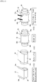
- Fig. 1 includes schematic illustrations showing the first cover forming step of the method of manufacturing a pneumatic tire in accordance with an embodiment of the present invention.
- first, sidewalls (sw) 34a, 34b are wrapped on opposite sides of a first forming drum 30, and then, at the central portion of first forming drum 30, a sheet-shaped inner liner 32 and a ply 35 are pasted.
- a pair of beads 36a, 36b is set inner than sidewalls 34a, 34b.
- the space between the pair of beads 36a, 36b to be set is appropriately selected in accordance with the width of the tire product.
- tread rubber materials 12a, 12b are wound spirally (strip-winding), whereby sides 13a, 13b of tread (see Fig. 3 ) are formed
- formation of the first cover 38 is completed. Winding of tread rubber material 12a, 12b may be performed before setting the pair of beads 36a, 36b.
- Tread sides 13a and 13b are formed appropriately at positions outside a JLB (joint less band) 24, which will be described later, inner than beads 36a, 36b, to be adjacent to respective ends of the center of tread formed on the tread ring when the first cover 38 is inflated at the shaping step described later.
- JLB joint less band
- Fig. 2 includes schematic illustrations showing the tread ring forming step of the method of manufacturing a pneumatic tire in accordance with an embodiment of the present invention.
- first, two sheet-shaped breakers 22 are wrapped around and pasted on a second forming drum 20 and, thereafter, JLB 24 is formed by strip-winding on the breaker 22.
- strip-shaped tread rubber material 10b is wrapped spirally by strip-winding and thus, a center10 of tread (see Fig. 3 ) is formed. Thus, forming of tread ring 26 is completed.
- Fig. 3 includes schematic illustrations showing the shaping step of the method of manufacturing a pneumatic tire in accordance with an embodiment of the present invention. As shown in Fig. 3 , at the shaping step, first, the first cover 38 is inserted to the inside of cylindrical tread ring 26 and combined.
- the first cover 38 between the beads 36a, 36b is inflated, so that tread ring 26 and the first cover 38 are pressure-bonded, and the resulting body as a whole is formed to have the shape of a low cover.
- Fig. 4 includes schematic illustrations showing processes from the shaping step to the turn-up step of the method of manufacturing a pneumatic tire in accordance with an embodiment of the present invention, depicting a right-half of a symmetrical structure.
- sidewall 34a outside bead 36a is turned up and pasted to a side surface of inflated first cover 38 and, as shown in Fig. 4(B) , the side 13a of tread on the first cover 38 and the center 10 of tread on tread ring 26 are bonded together to form tread 1, and thus, formation of the low cover of pneumatic tire having the SOT structure is completed.
- the side 13a and the center 10 of tread are bonded appropriately overlapped in the axial direction of the tire. Specifically, overlapping by at least 5 mm is preferred.
- the bonding surface between the side 13a and the center 10 of tread should preferably be a shape as shown in Fig. 5(A), (B) or (C) , or a tapered surface, tapered from the outer surface side to the inner surface side of the tread, inclined to the sidewall
- the low cover made in this manner is vulcanized by a tire-vulcanizer and a pneumatic tire is manufactured.
- the bonded side 13a and center 10 of tread are formed of rubber having the same composition and, therefore, during vulcanization, these are integrated and form the tread of pneumatic tire. Therefore, by using the method of manufacturing a pneumatic tire in accordance with the present embodiment, a pneumatic tire having the SOT structure similar to the conventional pneumatic tire shown in Fig .6 can appropriately be manufactured without necessitating the conventional stitch-down step.
- 1a, 1b and 1c represent various types of treads in accordance with the present embodiment
- 50a, 50b and 50c represent various types of treads in accordance with the conventional method of manufacturing a pneumatic tire.
- the tread which has been formed as one body, is formed separately as a center and sides of tread, the center of tread is formed on the tread ring and the sides are formed on the first cover, and these are bonded when the low cover is made. Therefore, various problems occurred in the conventional method of manufacturing a pneumatic tire can be solved.
- the tread ring is made smaller in diameter by compressing rubber while the drum is being rotated, so as to make the tread extend along the first cover. Therefore, if the speed of rotation is increased, the shape of low cover comes to be nonuniform and it becomes more difficult to maintain shape accuracy.
- stitcher roller it may slip over the tread surface, possibly causing scratches or wrinkles on the tread.
- the tread is formed separately as a center and sides of tread, the center is formed on the tread ring and the sides are formed on the first cover, and the center and sides are bonded simultaneously with the shaping of the first cover, as described above.
- the shape of low cover can be maintained with high accuracy, and a pneumatic tire having stable tire performance such as FV can be manufactured with high efficiency.
- the pneumatic tire thus manufactured has the same structure as the conventional tires, as described above.
- the equipment for the stitch-down step can be simplified or made unnecessary, and therefore, production efficiency can further be improved.
- the center of tread is formed to have the width substantially the same as the breaker or the band, and the sides of tread that have been subjected to stitch-down are formed on the first cover. Therefore, unlike the conventional method, the difficulty of bending rubber of high stiffness along the first cover and pasting it thereon can be avoided. As a result, the first cover and the tread ring can reliably be integrated regardless of the length or gauge of the tread, and low covers of high quality can be manufactured stably with high reproducibility.
- An end of the tread entering a buttress portion of a pneumatic tire has, depending on its hardness, an influence on steering stability as well as RRC (Rolling Resistance Coefficient of tire) of a vehicle when the tire is mounted.
- RRC Rolling Resistance Coefficient of tire
- Example 5 stitch-down was conducted using a stitcher.
- the stitcher was moved straight (1-dimensional), while in Example 3, it was moved two-dimensionally, as in the conventional example.
- the frequency of collapse of strips was lower than the conventional example.
- the pneumatic tire can be manufactured with higher efficiency than the conventional example.
- collapse of strips did not occur at all, and pneumatic tires could be formed reliably.
Landscapes
- Engineering & Computer Science (AREA)
- Mechanical Engineering (AREA)
- Tyre Moulding (AREA)
Applications Claiming Priority (2)
| Application Number | Priority Date | Filing Date | Title |
|---|---|---|---|
| JP2014228349A JP6177220B2 (ja) | 2014-11-10 | 2014-11-10 | 空気入りタイヤの製造方法および空気入りタイヤ |
| PCT/JP2015/081044 WO2016076176A1 (fr) | 2014-11-10 | 2015-11-04 | Pneumatique ainsi que procédé de fabrication de celui-ci |
Publications (3)
| Publication Number | Publication Date |
|---|---|
| EP3205490A1 true EP3205490A1 (fr) | 2017-08-16 |
| EP3205490A4 EP3205490A4 (fr) | 2018-04-25 |
| EP3205490B1 EP3205490B1 (fr) | 2020-08-19 |
Family
ID=55954266
Family Applications (1)
| Application Number | Title | Priority Date | Filing Date |
|---|---|---|---|
| EP15859331.9A Active EP3205490B1 (fr) | 2014-11-10 | 2015-11-04 | Procédé de fabrication d'un pneumatique |
Country Status (5)
| Country | Link |
|---|---|
| US (1) | US10538047B2 (fr) |
| EP (1) | EP3205490B1 (fr) |
| JP (1) | JP6177220B2 (fr) |
| CN (1) | CN107073857B (fr) |
| WO (1) | WO2016076176A1 (fr) |
Families Citing this family (3)
| Publication number | Priority date | Publication date | Assignee | Title |
|---|---|---|---|---|
| WO2020230576A1 (fr) | 2019-05-13 | 2020-11-19 | 住友ゴム工業株式会社 | Pneu et son procédé de fabrication |
| CN111976180A (zh) * | 2020-07-02 | 2020-11-24 | 赛轮(沈阳)轮胎有限公司 | 全钢三鼓旋拉反包胎侧压合方法及装置 |
| CN117597229A (zh) * | 2021-06-18 | 2024-02-23 | 普利司通美国轮胎运营有限责任公司 | 用于非充气轮胎的固化模具组件以及制造方法 |
Family Cites Families (11)
| Publication number | Priority date | Publication date | Assignee | Title |
|---|---|---|---|---|
| US4007069A (en) | 1970-12-29 | 1977-02-08 | Bridgestone Tire Company Limited | Process for making radial tires |
| WO1999048706A1 (fr) * | 1998-03-27 | 1999-09-30 | The Goodyear Tire & Rubber Company | Bande de roulement de pneu amelioree et construction de flancs |
| JP4256149B2 (ja) * | 2002-11-25 | 2009-04-22 | 株式会社ブリヂストン | 空気入りタイヤ |
| JP4612372B2 (ja) * | 2004-09-13 | 2011-01-12 | 住友ゴム工業株式会社 | 空気入りタイヤ、及びその製造方法 |
| JP4546812B2 (ja) | 2004-12-02 | 2010-09-22 | 住友ゴム工業株式会社 | 空気入りタイヤ |
| JP4392400B2 (ja) * | 2005-11-09 | 2009-12-24 | 住友ゴム工業株式会社 | 空気入りタイヤ |
| CN101535065A (zh) | 2006-10-11 | 2009-09-16 | 东洋橡胶工业株式会社 | 充气轮胎 |
| JP4939344B2 (ja) * | 2007-08-28 | 2012-05-23 | 住友ゴム工業株式会社 | 空気入りタイヤ、及びその製造方法 |
| ITTO20100323A1 (it) | 2010-04-20 | 2011-10-21 | Bridgestone Corp | Metodo di costruzione di un pneumatico mediante un unico tamburo di formatura |
| JP2013039695A (ja) * | 2011-08-12 | 2013-02-28 | Sumitomo Rubber Ind Ltd | 空気入りタイヤの製造方法 |
| JP5721651B2 (ja) * | 2012-03-12 | 2015-05-20 | 住友ゴム工業株式会社 | 生タイヤ成形用圧着装置および生タイヤ成形方法 |
-
2014
- 2014-11-10 JP JP2014228349A patent/JP6177220B2/ja active Active
-
2015
- 2015-11-04 EP EP15859331.9A patent/EP3205490B1/fr active Active
- 2015-11-04 CN CN201580058226.XA patent/CN107073857B/zh active Active
- 2015-11-04 WO PCT/JP2015/081044 patent/WO2016076176A1/fr not_active Ceased
- 2015-11-04 US US15/523,600 patent/US10538047B2/en not_active Expired - Fee Related
Also Published As
| Publication number | Publication date |
|---|---|
| US20170313006A1 (en) | 2017-11-02 |
| CN107073857B (zh) | 2019-05-10 |
| CN107073857A (zh) | 2017-08-18 |
| EP3205490B1 (fr) | 2020-08-19 |
| JP6177220B2 (ja) | 2017-08-09 |
| EP3205490A4 (fr) | 2018-04-25 |
| WO2016076176A1 (fr) | 2016-05-19 |
| JP2016088031A (ja) | 2016-05-23 |
| US10538047B2 (en) | 2020-01-21 |
Similar Documents
| Publication | Publication Date | Title |
|---|---|---|
| CN102642318B (zh) | 充气轮胎的制造方法 | |
| CN1962291A (zh) | 充气轮胎及其制造方法和用于此轮胎中的缓冲橡胶 | |
| WO2014030470A1 (fr) | Procédé de fabrication pour pneu, et pneu | |
| JP5952963B2 (ja) | ゴムストリップ貼付け方法、それを用いた空気入りタイヤの製造方法、及び、貼付け装置 | |
| EP3205490B1 (fr) | Procédé de fabrication d'un pneumatique | |
| EP3205488B1 (fr) | Procédé de fabrication d'un pneumatique | |
| EP3205489B1 (fr) | Procédé de fabrication d'un pneumatique | |
| CN103158441B (zh) | 充气轮胎及其制造方法 | |
| JP6306975B2 (ja) | 空気入りタイヤの製造方法 | |
| JP7434904B2 (ja) | 生タイヤの製造方法 | |
| CN104640691B (zh) | 刚性型芯以及使用该刚性型芯的充气轮胎的制造方法 | |
| JP4960592B2 (ja) | トレッドリングの形成方法 | |
| US20200164688A1 (en) | Method for manufacturing tire | |
| JP6450207B2 (ja) | 空気入りタイヤの製造方法 | |
| JP2009172961A (ja) | タイヤ成型方法及びタイヤ製造方法 | |
| JP6794664B2 (ja) | 生タイヤの製造方法 | |
| JP2005212325A (ja) | 空気入り安全タイヤの製造方法 |
Legal Events
| Date | Code | Title | Description |
|---|---|---|---|
| STAA | Information on the status of an ep patent application or granted ep patent |
Free format text: STATUS: THE INTERNATIONAL PUBLICATION HAS BEEN MADE |
|
| PUAI | Public reference made under article 153(3) epc to a published international application that has entered the european phase |
Free format text: ORIGINAL CODE: 0009012 |
|
| STAA | Information on the status of an ep patent application or granted ep patent |
Free format text: STATUS: REQUEST FOR EXAMINATION WAS MADE |
|
| 17P | Request for examination filed |
Effective date: 20170512 |
|
| AK | Designated contracting states |
Kind code of ref document: A1 Designated state(s): AL AT BE BG CH CY CZ DE DK EE ES FI FR GB GR HR HU IE IS IT LI LT LU LV MC MK MT NL NO PL PT RO RS SE SI SK SM TR |
|
| AX | Request for extension of the european patent |
Extension state: BA ME |
|
| DAV | Request for validation of the european patent (deleted) | ||
| DAX | Request for extension of the european patent (deleted) | ||
| A4 | Supplementary search report drawn up and despatched |
Effective date: 20180323 |
|
| RIC1 | Information provided on ipc code assigned before grant |
Ipc: B29D 30/30 20060101AFI20180319BHEP |
|
| STAA | Information on the status of an ep patent application or granted ep patent |
Free format text: STATUS: EXAMINATION IS IN PROGRESS |
|
| 17Q | First examination report despatched |
Effective date: 20191025 |
|
| GRAP | Despatch of communication of intention to grant a patent |
Free format text: ORIGINAL CODE: EPIDOSNIGR1 |
|
| STAA | Information on the status of an ep patent application or granted ep patent |
Free format text: STATUS: GRANT OF PATENT IS INTENDED |
|
| INTG | Intention to grant announced |
Effective date: 20200526 |
|
| GRAS | Grant fee paid |
Free format text: ORIGINAL CODE: EPIDOSNIGR3 |
|
| GRAA | (expected) grant |
Free format text: ORIGINAL CODE: 0009210 |
|
| STAA | Information on the status of an ep patent application or granted ep patent |
Free format text: STATUS: THE PATENT HAS BEEN GRANTED |
|
| AK | Designated contracting states |
Kind code of ref document: B1 Designated state(s): AL AT BE BG CH CY CZ DE DK EE ES FI FR GB GR HR HU IE IS IT LI LT LU LV MC MK MT NL NO PL PT RO RS SE SI SK SM TR |
|
| REG | Reference to a national code |
Ref country code: CH Ref legal event code: EP |
|
| REG | Reference to a national code |
Ref country code: DE Ref legal event code: R096 Ref document number: 602015057858 Country of ref document: DE |
|
| REG | Reference to a national code |
Ref country code: AT Ref legal event code: REF Ref document number: 1303468 Country of ref document: AT Kind code of ref document: T Effective date: 20200915 |
|
| REG | Reference to a national code |
Ref country code: IE Ref legal event code: FG4D |
|
| REG | Reference to a national code |
Ref country code: LT Ref legal event code: MG4D |
|
| REG | Reference to a national code |
Ref country code: NL Ref legal event code: MP Effective date: 20200819 |
|
| PG25 | Lapsed in a contracting state [announced via postgrant information from national office to epo] |
Ref country code: HR Free format text: LAPSE BECAUSE OF FAILURE TO SUBMIT A TRANSLATION OF THE DESCRIPTION OR TO PAY THE FEE WITHIN THE PRESCRIBED TIME-LIMIT Effective date: 20200819 Ref country code: LT Free format text: LAPSE BECAUSE OF FAILURE TO SUBMIT A TRANSLATION OF THE DESCRIPTION OR TO PAY THE FEE WITHIN THE PRESCRIBED TIME-LIMIT Effective date: 20200819 Ref country code: BG Free format text: LAPSE BECAUSE OF FAILURE TO SUBMIT A TRANSLATION OF THE DESCRIPTION OR TO PAY THE FEE WITHIN THE PRESCRIBED TIME-LIMIT Effective date: 20201119 Ref country code: SE Free format text: LAPSE BECAUSE OF FAILURE TO SUBMIT A TRANSLATION OF THE DESCRIPTION OR TO PAY THE FEE WITHIN THE PRESCRIBED TIME-LIMIT Effective date: 20200819 Ref country code: FI Free format text: LAPSE BECAUSE OF FAILURE TO SUBMIT A TRANSLATION OF THE DESCRIPTION OR TO PAY THE FEE WITHIN THE PRESCRIBED TIME-LIMIT Effective date: 20200819 Ref country code: PT Free format text: LAPSE BECAUSE OF FAILURE TO SUBMIT A TRANSLATION OF THE DESCRIPTION OR TO PAY THE FEE WITHIN THE PRESCRIBED TIME-LIMIT Effective date: 20201221 Ref country code: NO Free format text: LAPSE BECAUSE OF FAILURE TO SUBMIT A TRANSLATION OF THE DESCRIPTION OR TO PAY THE FEE WITHIN THE PRESCRIBED TIME-LIMIT Effective date: 20201119 Ref country code: GR Free format text: LAPSE BECAUSE OF FAILURE TO SUBMIT A TRANSLATION OF THE DESCRIPTION OR TO PAY THE FEE WITHIN THE PRESCRIBED TIME-LIMIT Effective date: 20201120 |
|
| REG | Reference to a national code |
Ref country code: AT Ref legal event code: MK05 Ref document number: 1303468 Country of ref document: AT Kind code of ref document: T Effective date: 20200819 |
|
| PG25 | Lapsed in a contracting state [announced via postgrant information from national office to epo] |
Ref country code: LV Free format text: LAPSE BECAUSE OF FAILURE TO SUBMIT A TRANSLATION OF THE DESCRIPTION OR TO PAY THE FEE WITHIN THE PRESCRIBED TIME-LIMIT Effective date: 20200819 Ref country code: NL Free format text: LAPSE BECAUSE OF FAILURE TO SUBMIT A TRANSLATION OF THE DESCRIPTION OR TO PAY THE FEE WITHIN THE PRESCRIBED TIME-LIMIT Effective date: 20200819 Ref country code: RS Free format text: LAPSE BECAUSE OF FAILURE TO SUBMIT A TRANSLATION OF THE DESCRIPTION OR TO PAY THE FEE WITHIN THE PRESCRIBED TIME-LIMIT Effective date: 20200819 Ref country code: PL Free format text: LAPSE BECAUSE OF FAILURE TO SUBMIT A TRANSLATION OF THE DESCRIPTION OR TO PAY THE FEE WITHIN THE PRESCRIBED TIME-LIMIT Effective date: 20200819 Ref country code: IS Free format text: LAPSE BECAUSE OF FAILURE TO SUBMIT A TRANSLATION OF THE DESCRIPTION OR TO PAY THE FEE WITHIN THE PRESCRIBED TIME-LIMIT Effective date: 20201219 |
|
| PG25 | Lapsed in a contracting state [announced via postgrant information from national office to epo] |
Ref country code: DK Free format text: LAPSE BECAUSE OF FAILURE TO SUBMIT A TRANSLATION OF THE DESCRIPTION OR TO PAY THE FEE WITHIN THE PRESCRIBED TIME-LIMIT Effective date: 20200819 Ref country code: CZ Free format text: LAPSE BECAUSE OF FAILURE TO SUBMIT A TRANSLATION OF THE DESCRIPTION OR TO PAY THE FEE WITHIN THE PRESCRIBED TIME-LIMIT Effective date: 20200819 Ref country code: EE Free format text: LAPSE BECAUSE OF FAILURE TO SUBMIT A TRANSLATION OF THE DESCRIPTION OR TO PAY THE FEE WITHIN THE PRESCRIBED TIME-LIMIT Effective date: 20200819 Ref country code: RO Free format text: LAPSE BECAUSE OF FAILURE TO SUBMIT A TRANSLATION OF THE DESCRIPTION OR TO PAY THE FEE WITHIN THE PRESCRIBED TIME-LIMIT Effective date: 20200819 Ref country code: SM Free format text: LAPSE BECAUSE OF FAILURE TO SUBMIT A TRANSLATION OF THE DESCRIPTION OR TO PAY THE FEE WITHIN THE PRESCRIBED TIME-LIMIT Effective date: 20200819 |
|
| REG | Reference to a national code |
Ref country code: DE Ref legal event code: R097 Ref document number: 602015057858 Country of ref document: DE |
|
| PG25 | Lapsed in a contracting state [announced via postgrant information from national office to epo] |
Ref country code: ES Free format text: LAPSE BECAUSE OF FAILURE TO SUBMIT A TRANSLATION OF THE DESCRIPTION OR TO PAY THE FEE WITHIN THE PRESCRIBED TIME-LIMIT Effective date: 20200819 Ref country code: AT Free format text: LAPSE BECAUSE OF FAILURE TO SUBMIT A TRANSLATION OF THE DESCRIPTION OR TO PAY THE FEE WITHIN THE PRESCRIBED TIME-LIMIT Effective date: 20200819 Ref country code: AL Free format text: LAPSE BECAUSE OF FAILURE TO SUBMIT A TRANSLATION OF THE DESCRIPTION OR TO PAY THE FEE WITHIN THE PRESCRIBED TIME-LIMIT Effective date: 20200819 |
|
| PLBE | No opposition filed within time limit |
Free format text: ORIGINAL CODE: 0009261 |
|
| STAA | Information on the status of an ep patent application or granted ep patent |
Free format text: STATUS: NO OPPOSITION FILED WITHIN TIME LIMIT |
|
| PG25 | Lapsed in a contracting state [announced via postgrant information from national office to epo] |
Ref country code: MC Free format text: LAPSE BECAUSE OF FAILURE TO SUBMIT A TRANSLATION OF THE DESCRIPTION OR TO PAY THE FEE WITHIN THE PRESCRIBED TIME-LIMIT Effective date: 20200819 Ref country code: SK Free format text: LAPSE BECAUSE OF FAILURE TO SUBMIT A TRANSLATION OF THE DESCRIPTION OR TO PAY THE FEE WITHIN THE PRESCRIBED TIME-LIMIT Effective date: 20200819 |
|
| REG | Reference to a national code |
Ref country code: CH Ref legal event code: PL |
|
| 26N | No opposition filed |
Effective date: 20210520 |
|
| GBPC | Gb: european patent ceased through non-payment of renewal fee |
Effective date: 20201119 |
|
| PG25 | Lapsed in a contracting state [announced via postgrant information from national office to epo] |
Ref country code: LU Free format text: LAPSE BECAUSE OF NON-PAYMENT OF DUE FEES Effective date: 20201104 Ref country code: IT Free format text: LAPSE BECAUSE OF FAILURE TO SUBMIT A TRANSLATION OF THE DESCRIPTION OR TO PAY THE FEE WITHIN THE PRESCRIBED TIME-LIMIT Effective date: 20200819 |
|
| REG | Reference to a national code |
Ref country code: BE Ref legal event code: MM Effective date: 20201130 |
|
| PG25 | Lapsed in a contracting state [announced via postgrant information from national office to epo] |
Ref country code: LI Free format text: LAPSE BECAUSE OF NON-PAYMENT OF DUE FEES Effective date: 20201130 Ref country code: SI Free format text: LAPSE BECAUSE OF FAILURE TO SUBMIT A TRANSLATION OF THE DESCRIPTION OR TO PAY THE FEE WITHIN THE PRESCRIBED TIME-LIMIT Effective date: 20200819 Ref country code: CH Free format text: LAPSE BECAUSE OF NON-PAYMENT OF DUE FEES Effective date: 20201130 |
|
| PG25 | Lapsed in a contracting state [announced via postgrant information from national office to epo] |
Ref country code: IE Free format text: LAPSE BECAUSE OF NON-PAYMENT OF DUE FEES Effective date: 20201104 |
|
| PG25 | Lapsed in a contracting state [announced via postgrant information from national office to epo] |
Ref country code: GB Free format text: LAPSE BECAUSE OF NON-PAYMENT OF DUE FEES Effective date: 20201119 |
|
| PG25 | Lapsed in a contracting state [announced via postgrant information from national office to epo] |
Ref country code: IS Free format text: LAPSE BECAUSE OF FAILURE TO SUBMIT A TRANSLATION OF THE DESCRIPTION OR TO PAY THE FEE WITHIN THE PRESCRIBED TIME-LIMIT Effective date: 20201219 Ref country code: TR Free format text: LAPSE BECAUSE OF FAILURE TO SUBMIT A TRANSLATION OF THE DESCRIPTION OR TO PAY THE FEE WITHIN THE PRESCRIBED TIME-LIMIT Effective date: 20200819 Ref country code: MT Free format text: LAPSE BECAUSE OF FAILURE TO SUBMIT A TRANSLATION OF THE DESCRIPTION OR TO PAY THE FEE WITHIN THE PRESCRIBED TIME-LIMIT Effective date: 20200819 Ref country code: CY Free format text: LAPSE BECAUSE OF FAILURE TO SUBMIT A TRANSLATION OF THE DESCRIPTION OR TO PAY THE FEE WITHIN THE PRESCRIBED TIME-LIMIT Effective date: 20200819 |
|
| PG25 | Lapsed in a contracting state [announced via postgrant information from national office to epo] |
Ref country code: MK Free format text: LAPSE BECAUSE OF FAILURE TO SUBMIT A TRANSLATION OF THE DESCRIPTION OR TO PAY THE FEE WITHIN THE PRESCRIBED TIME-LIMIT Effective date: 20200819 |
|
| PG25 | Lapsed in a contracting state [announced via postgrant information from national office to epo] |
Ref country code: BE Free format text: LAPSE BECAUSE OF NON-PAYMENT OF DUE FEES Effective date: 20201130 |
|
| P01 | Opt-out of the competence of the unified patent court (upc) registered |
Effective date: 20230510 |
|
| PGFP | Annual fee paid to national office [announced via postgrant information from national office to epo] |
Ref country code: FR Payment date: 20250930 Year of fee payment: 11 |
|
| PGFP | Annual fee paid to national office [announced via postgrant information from national office to epo] |
Ref country code: DE Payment date: 20250930 Year of fee payment: 11 |