EP3205523A1 - Structure de positionnement de batterie de véhicule électrique - Google Patents
Structure de positionnement de batterie de véhicule électrique Download PDFInfo
- Publication number
- EP3205523A1 EP3205523A1 EP17159346.0A EP17159346A EP3205523A1 EP 3205523 A1 EP3205523 A1 EP 3205523A1 EP 17159346 A EP17159346 A EP 17159346A EP 3205523 A1 EP3205523 A1 EP 3205523A1
- Authority
- EP
- European Patent Office
- Prior art keywords
- battery
- brackets
- bracket
- battery modules
- positioning structure
- Prior art date
- Legal status (The legal status is an assumption and is not a legal conclusion. Google has not performed a legal analysis and makes no representation as to the accuracy of the status listed.)
- Granted
Links
Images


Classifications
-
- H—ELECTRICITY
- H01—ELECTRIC ELEMENTS
- H01M—PROCESSES OR MEANS, e.g. BATTERIES, FOR THE DIRECT CONVERSION OF CHEMICAL ENERGY INTO ELECTRICAL ENERGY
- H01M50/00—Constructional details or processes of manufacture of the non-active parts of electrochemical cells other than fuel cells, e.g. hybrid cells
- H01M50/20—Mountings; Secondary casings or frames; Racks, modules or packs; Suspension devices; Shock absorbers; Transport or carrying devices; Holders
- H01M50/258—Modular batteries; Casings provided with means for assembling
- H01M50/26—Assemblies sealed to each other in a non-detachable manner
-
- B—PERFORMING OPERATIONS; TRANSPORTING
- B60—VEHICLES IN GENERAL
- B60K—ARRANGEMENT OR MOUNTING OF PROPULSION UNITS OR OF TRANSMISSIONS IN VEHICLES; ARRANGEMENT OR MOUNTING OF PLURAL DIVERSE PRIME-MOVERS IN VEHICLES; AUXILIARY DRIVES FOR VEHICLES; INSTRUMENTATION OR DASHBOARDS FOR VEHICLES; ARRANGEMENTS IN CONNECTION WITH COOLING, AIR INTAKE, GAS EXHAUST OR FUEL SUPPLY OF PROPULSION UNITS IN VEHICLES
- B60K1/00—Arrangement or mounting of electrical propulsion units
- B60K1/04—Arrangement or mounting of electrical propulsion units of the electric storage means for propulsion
-
- B—PERFORMING OPERATIONS; TRANSPORTING
- B60—VEHICLES IN GENERAL
- B60L—PROPULSION OF ELECTRICALLY-PROPELLED VEHICLES; SUPPLYING ELECTRIC POWER FOR AUXILIARY EQUIPMENT OF ELECTRICALLY-PROPELLED VEHICLES; ELECTRODYNAMIC BRAKE SYSTEMS FOR VEHICLES IN GENERAL; MAGNETIC SUSPENSION OR LEVITATION FOR VEHICLES; MONITORING OPERATING VARIABLES OF ELECTRICALLY-PROPELLED VEHICLES; ELECTRIC SAFETY DEVICES FOR ELECTRICALLY-PROPELLED VEHICLES
- B60L50/00—Electric propulsion with power supplied within the vehicle
- B60L50/50—Electric propulsion with power supplied within the vehicle using propulsion power supplied by batteries or fuel cells
- B60L50/60—Electric propulsion with power supplied within the vehicle using propulsion power supplied by batteries or fuel cells using power supplied by batteries
- B60L50/64—Constructional details of batteries specially adapted for electric vehicles
-
- B—PERFORMING OPERATIONS; TRANSPORTING
- B60—VEHICLES IN GENERAL
- B60L—PROPULSION OF ELECTRICALLY-PROPELLED VEHICLES; SUPPLYING ELECTRIC POWER FOR AUXILIARY EQUIPMENT OF ELECTRICALLY-PROPELLED VEHICLES; ELECTRODYNAMIC BRAKE SYSTEMS FOR VEHICLES IN GENERAL; MAGNETIC SUSPENSION OR LEVITATION FOR VEHICLES; MONITORING OPERATING VARIABLES OF ELECTRICALLY-PROPELLED VEHICLES; ELECTRIC SAFETY DEVICES FOR ELECTRICALLY-PROPELLED VEHICLES
- B60L50/00—Electric propulsion with power supplied within the vehicle
- B60L50/50—Electric propulsion with power supplied within the vehicle using propulsion power supplied by batteries or fuel cells
- B60L50/60—Electric propulsion with power supplied within the vehicle using propulsion power supplied by batteries or fuel cells using power supplied by batteries
- B60L50/66—Arrangements of batteries
-
- H—ELECTRICITY
- H01—ELECTRIC ELEMENTS
- H01M—PROCESSES OR MEANS, e.g. BATTERIES, FOR THE DIRECT CONVERSION OF CHEMICAL ENERGY INTO ELECTRICAL ENERGY
- H01M50/00—Constructional details or processes of manufacture of the non-active parts of electrochemical cells other than fuel cells, e.g. hybrid cells
- H01M50/20—Mountings; Secondary casings or frames; Racks, modules or packs; Suspension devices; Shock absorbers; Transport or carrying devices; Holders
- H01M50/204—Racks, modules or packs for multiple batteries or multiple cells
-
- H—ELECTRICITY
- H01—ELECTRIC ELEMENTS
- H01M—PROCESSES OR MEANS, e.g. BATTERIES, FOR THE DIRECT CONVERSION OF CHEMICAL ENERGY INTO ELECTRICAL ENERGY
- H01M50/00—Constructional details or processes of manufacture of the non-active parts of electrochemical cells other than fuel cells, e.g. hybrid cells
- H01M50/20—Mountings; Secondary casings or frames; Racks, modules or packs; Suspension devices; Shock absorbers; Transport or carrying devices; Holders
- H01M50/233—Mountings; Secondary casings or frames; Racks, modules or packs; Suspension devices; Shock absorbers; Transport or carrying devices; Holders characterised by physical properties of casings or racks, e.g. dimensions
- H01M50/242—Mountings; Secondary casings or frames; Racks, modules or packs; Suspension devices; Shock absorbers; Transport or carrying devices; Holders characterised by physical properties of casings or racks, e.g. dimensions adapted for protecting batteries against vibrations, collision impact or swelling
-
- H—ELECTRICITY
- H01—ELECTRIC ELEMENTS
- H01M—PROCESSES OR MEANS, e.g. BATTERIES, FOR THE DIRECT CONVERSION OF CHEMICAL ENERGY INTO ELECTRICAL ENERGY
- H01M50/00—Constructional details or processes of manufacture of the non-active parts of electrochemical cells other than fuel cells, e.g. hybrid cells
- H01M50/20—Mountings; Secondary casings or frames; Racks, modules or packs; Suspension devices; Shock absorbers; Transport or carrying devices; Holders
- H01M50/244—Secondary casings; Racks; Suspension devices; Carrying devices; Holders characterised by their mounting method
-
- H—ELECTRICITY
- H01—ELECTRIC ELEMENTS
- H01M—PROCESSES OR MEANS, e.g. BATTERIES, FOR THE DIRECT CONVERSION OF CHEMICAL ENERGY INTO ELECTRICAL ENERGY
- H01M50/00—Constructional details or processes of manufacture of the non-active parts of electrochemical cells other than fuel cells, e.g. hybrid cells
- H01M50/20—Mountings; Secondary casings or frames; Racks, modules or packs; Suspension devices; Shock absorbers; Transport or carrying devices; Holders
- H01M50/249—Mountings; Secondary casings or frames; Racks, modules or packs; Suspension devices; Shock absorbers; Transport or carrying devices; Holders specially adapted for aircraft or vehicles, e.g. cars or trains
-
- H—ELECTRICITY
- H01—ELECTRIC ELEMENTS
- H01M—PROCESSES OR MEANS, e.g. BATTERIES, FOR THE DIRECT CONVERSION OF CHEMICAL ENERGY INTO ELECTRICAL ENERGY
- H01M50/00—Constructional details or processes of manufacture of the non-active parts of electrochemical cells other than fuel cells, e.g. hybrid cells
- H01M50/20—Mountings; Secondary casings or frames; Racks, modules or packs; Suspension devices; Shock absorbers; Transport or carrying devices; Holders
- H01M50/262—Mountings; Secondary casings or frames; Racks, modules or packs; Suspension devices; Shock absorbers; Transport or carrying devices; Holders with fastening means, e.g. locks
-
- B—PERFORMING OPERATIONS; TRANSPORTING
- B60—VEHICLES IN GENERAL
- B60K—ARRANGEMENT OR MOUNTING OF PROPULSION UNITS OR OF TRANSMISSIONS IN VEHICLES; ARRANGEMENT OR MOUNTING OF PLURAL DIVERSE PRIME-MOVERS IN VEHICLES; AUXILIARY DRIVES FOR VEHICLES; INSTRUMENTATION OR DASHBOARDS FOR VEHICLES; ARRANGEMENTS IN CONNECTION WITH COOLING, AIR INTAKE, GAS EXHAUST OR FUEL SUPPLY OF PROPULSION UNITS IN VEHICLES
- B60K1/00—Arrangement or mounting of electrical propulsion units
- B60K2001/003—Arrangement or mounting of electrical propulsion units with means for cooling the electrical propulsion units
- B60K2001/005—Arrangement or mounting of electrical propulsion units with means for cooling the electrical propulsion units the electric storage means
-
- B—PERFORMING OPERATIONS; TRANSPORTING
- B60—VEHICLES IN GENERAL
- B60K—ARRANGEMENT OR MOUNTING OF PROPULSION UNITS OR OF TRANSMISSIONS IN VEHICLES; ARRANGEMENT OR MOUNTING OF PLURAL DIVERSE PRIME-MOVERS IN VEHICLES; AUXILIARY DRIVES FOR VEHICLES; INSTRUMENTATION OR DASHBOARDS FOR VEHICLES; ARRANGEMENTS IN CONNECTION WITH COOLING, AIR INTAKE, GAS EXHAUST OR FUEL SUPPLY OF PROPULSION UNITS IN VEHICLES
- B60K1/00—Arrangement or mounting of electrical propulsion units
- B60K1/04—Arrangement or mounting of electrical propulsion units of the electric storage means for propulsion
- B60K2001/0405—Arrangement or mounting of electrical propulsion units of the electric storage means for propulsion characterised by their position
- B60K2001/0422—Arrangement under the front seats
-
- B—PERFORMING OPERATIONS; TRANSPORTING
- B60—VEHICLES IN GENERAL
- B60K—ARRANGEMENT OR MOUNTING OF PROPULSION UNITS OR OF TRANSMISSIONS IN VEHICLES; ARRANGEMENT OR MOUNTING OF PLURAL DIVERSE PRIME-MOVERS IN VEHICLES; AUXILIARY DRIVES FOR VEHICLES; INSTRUMENTATION OR DASHBOARDS FOR VEHICLES; ARRANGEMENTS IN CONNECTION WITH COOLING, AIR INTAKE, GAS EXHAUST OR FUEL SUPPLY OF PROPULSION UNITS IN VEHICLES
- B60K1/00—Arrangement or mounting of electrical propulsion units
- B60K1/04—Arrangement or mounting of electrical propulsion units of the electric storage means for propulsion
- B60K2001/0405—Arrangement or mounting of electrical propulsion units of the electric storage means for propulsion characterised by their position
- B60K2001/0433—Arrangement under the rear seats
-
- B—PERFORMING OPERATIONS; TRANSPORTING
- B60—VEHICLES IN GENERAL
- B60K—ARRANGEMENT OR MOUNTING OF PROPULSION UNITS OR OF TRANSMISSIONS IN VEHICLES; ARRANGEMENT OR MOUNTING OF PLURAL DIVERSE PRIME-MOVERS IN VEHICLES; AUXILIARY DRIVES FOR VEHICLES; INSTRUMENTATION OR DASHBOARDS FOR VEHICLES; ARRANGEMENTS IN CONNECTION WITH COOLING, AIR INTAKE, GAS EXHAUST OR FUEL SUPPLY OF PROPULSION UNITS IN VEHICLES
- B60K1/00—Arrangement or mounting of electrical propulsion units
- B60K1/04—Arrangement or mounting of electrical propulsion units of the electric storage means for propulsion
- B60K2001/0455—Removal or replacement of the energy storages
- B60K2001/0472—Removal or replacement of the energy storages from below
-
- Y—GENERAL TAGGING OF NEW TECHNOLOGICAL DEVELOPMENTS; GENERAL TAGGING OF CROSS-SECTIONAL TECHNOLOGIES SPANNING OVER SEVERAL SECTIONS OF THE IPC; TECHNICAL SUBJECTS COVERED BY FORMER USPC CROSS-REFERENCE ART COLLECTIONS [XRACs] AND DIGESTS
- Y02—TECHNOLOGIES OR APPLICATIONS FOR MITIGATION OR ADAPTATION AGAINST CLIMATE CHANGE
- Y02E—REDUCTION OF GREENHOUSE GAS [GHG] EMISSIONS, RELATED TO ENERGY GENERATION, TRANSMISSION OR DISTRIBUTION
- Y02E60/00—Enabling technologies; Technologies with a potential or indirect contribution to GHG emissions mitigation
- Y02E60/10—Energy storage using batteries
-
- Y—GENERAL TAGGING OF NEW TECHNOLOGICAL DEVELOPMENTS; GENERAL TAGGING OF CROSS-SECTIONAL TECHNOLOGIES SPANNING OVER SEVERAL SECTIONS OF THE IPC; TECHNICAL SUBJECTS COVERED BY FORMER USPC CROSS-REFERENCE ART COLLECTIONS [XRACs] AND DIGESTS
- Y02—TECHNOLOGIES OR APPLICATIONS FOR MITIGATION OR ADAPTATION AGAINST CLIMATE CHANGE
- Y02T—CLIMATE CHANGE MITIGATION TECHNOLOGIES RELATED TO TRANSPORTATION
- Y02T10/00—Road transport of goods or passengers
- Y02T10/60—Other road transportation technologies with climate change mitigation effect
- Y02T10/70—Energy storage systems for electromobility, e.g. batteries
Definitions
- the present invention relates to a battery positioning structure of an electric vehicle which includes a plurality of battery modules constituted by a plurality of battery cells.
- an electric vehicle is provided with a motor as a drive unit and a battery unit as a power source, and is driven by the motor which is actuated by power supplied by the battery unit.
- a travelling distance of the electric vehicle depends upon performance and capacity of the battery unit. Therefore, the electric vehicle generally includes the battery unit which is constituted by a plurality of battery modules containing rechargeable battery cells. Whenever a battery voltage is decreased, battery cells will be recharged.
- Patent Publication No. 3050010 discloses to fix battery modules to a vehicle body.
- a plurality of battery modules are mounted on a tray which is provided on the vehicle body.
- the battery modules are fastened, by using bolts or the like, to the tray using long and thin brackets which extend across the battery modules.
- the battery modules are placed on the tray, and are simultaneously held down by the bracket which is put on the battery modules. If the battery modules are different in their sizes, height and so on, there will spaces between low battery modules and the bracket. In such a case, the battery modules may become bumpy. When the bracket is excessively fastened in order to overcome this problem, tall battery modules will be subject to large fastening loads. Further, when the bracket is fastened on the tray by inserting bolts into screws of the tray, some screws will be covered by battery modules which should be placed on the tray. With the related art, it is possible to reduce the number of components but it seems that assembling work will become troublesome.
- the present invention is intended to provide a battery positioning structure which can reliably position battery modules in an electric vehicle even if battery modules have different sizes or heights.
- a battery positioning structure for an electric vehicle which includes a plurality of battery units constituted by battery modules.
- the battery positioning structure includes: a bracket having at opposite ends not only check plates which are configured to be positioned on a body of the electric vehicle but also locks at opposite side edges of the bracket, the bracket being configured to be attached to outer surfaces of the battery modules and to unite the battery cells, and bands configured to extend across the bracket and linked to the locks at opposite ends of the bracket, in which the battery modules and the bracket are positioned on the body of the electric vehicle.
- the bracket is made of a steel plate, and is attached around the battery modules except at module terminals.
- one of the check plates is detachably supported by the bracket.
- one of the check plates is detachably supported by the bracket.
- a battery positioning structure for an electric vehicle which includes a plurality of battery modules constituted by battery cells.
- the battery positioning structure includes: a pair of brackets configured to be attached to an outer surfaces of battery modules, and having check plates which are detachably attached to thereto and bands configured to extend across the brackets and tied to locks at opposite ends of the brackets.
- the battery modules and the brackets are positioned on the body of the electric vehicle.
- brackets are made of steel plates and are shaped not to come into contact with terminals of the battery modules.
- the metal bracket attached around the battery modules is fastened to bolts of the vehicle body, and is covered by bands.
- the bands are fixedly attached to locks. Even when battery modules have different sizes and heights, they can be reliably and efficiently positioned on the vehicle body since size and height differences of the battery modules can be absorbed depending upon where the bands are fastened to the locks.
- the metal bracket is attached on the outer surface of the battery modules at positions where there are no module terminals. Even if crashing energy is applied to the vehicle body, the bracket can reliably hold the battery modules on the vehicle body, do not come into contact with the module terminals, and protect the battery modules against crashing.
- one of check plates is detachably supported by the bracket.
- the bolts and check plates are aligned. Thereafter, the bracket is attached to the battery modules, and is fixed to the vehicle body with good workability.
- a pair of brackets are attached on outer surfaces of a plurality of battery modules, and unite the battery modules.
- the check plates with cylindrical parts to be attached to bolts of the vehicle body are temporarily attached to the brackets. Even if battery modules have different sizes or heights, they can be reliably and efficiently attached on the vehicle body without applying undue loads to the battery modules.
- the brackets are made of metal sheets, and are shaped not to come into contact with the module terminals. Even if battery module are moved due to crashing energy, the battery system can be reliably kept safe at the time of crashing.
- the battery positioning structure can position battery units with good reliability and workability even when battery modules have different sizes or heights.
- the battery positioning structure includes a bracket and bands. The battery modules are fitted into the bracket, and are firmly held by the bands which extend across the bracket, and have their opposite ends linked to locks at opposite side edges of the bracket.
- an electric vehicle 1 is driven by rotating wheels 3 which are rotated by a motor 2.
- the motor 2 is actuated by power supplied from a battery system 5.
- the battery system 5 is positioned under seats 4 in an interior of the electric vehicle.
- the battery system 5 is constituted by a plurality of battery units, each of which includes battery modules. Each battery module is constituted by one battery cell.
- the battery system 5 is housed in a battery container 8 defined by a floor panel 6 constituting a vehicle body and a shield plate 7 under the floor panel 6.
- the electric vehicle 1 includes a blower 14 and a compressor 18 which are located in an air intake path 13.
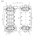
- the battery system 5 includes 12 battery units. Specifically, each battery unit is constituted by two battery modules 5a and 5b which are arranged in a moving direction Y of the electric vehicle 1. Six battery units are arranged in a direction X along a width of the electric vehicle 1, and constitute one battery group. Another battery group is positioned downstream of the foregoing battery group. In other words, the 12 battery units 5A to 5L are mounted on the shield plate 7, and are connected in series.
- the battery units 5A to 5L are positioned on the shield plate 7 using the same battery positioning structures as shown in Fig. 1 and Fig. 2 .
- One battery positioning structure will be described with reference to the battery unit 5A.
- the battery positioning structure holds the battery unit 5A using a bracket 21 and a plurality of bands 22, and is fixed on the shield plate 7 by inserting nuts (not shown) into bolts 23a and 23b provided on the shield plate 7.
- the bracket 21 is in the shape of a rectangular frame, and is attached to a periphery 5c of the battery unit5A at positions where there are no terminals 210 of the battery modules 5a and 5b. When attached, the bracket 21 becomes integral to the battery unit 5A.
- Check plates 24 and 25 are present at the opposite ends of the bracket 21, and are joined to the bolts 23a and 23b.
- Side surfaces 21c and 21d of the bracket 21 face with each other in the direction X, and have a plurality of locks 26 arranged in the moving direction Y of the electric vehicle 1.
- the bracket 21 and check plates 24 and 25 are made of steel plates.
- the check plates 24 and 25 are provided with cylindrical parts 24a and 25a.
- the cylindrical parts 24a and 25a receive the bolts 23a and 23b therein.
- Each of the bands 22 is in the shape of a gate, spans across the side surfaces 21c and 21d of the bracket 21, has its bent edges fitted into locks 26, and is fastened. Referring to Fig. 4(a) , each band 22 has teeth 27a and 27b at its ends 22a and 22b, and is movable in a direction Z.
- the locks 26 are positioned on the lower side edges 21c and 21d of the bracket 21.
- Each lock 26 has a recess 26A, is configured to be engaged with the teeth 27a and 27b of the band 22, and functions as a ratchet which enables the band 22 to be inserted but prevents it from being detached.
- the bracket 21 having the check plates 24 and 25 and locks 26 is attached, from an upper or lower side, to the periphery 5c of the two battery modules 5a and 5b which are laid side by side. In this state, the two battery modules 5a and 5b are united (as the battery unit 5A, for instance).
- a position of the bracket 21 to be attached to the battery cells 5a and 5b is at a height where the bolts 23a and 23b can be fitted into the cylindrical parts 24a and 25a.
- the battery unit 5A is positioned and fastened the vehicle body by the bolts 23a and 23b.
- each of the bands 22 is spanned over an outer surface of the bracket 21 from above the battery unit 5A (battery modules 5a and 5b) positioned on the shield plate 7.
- the opposite ends 22a and 22b of the band 22 are fitted into the recess 26A of the lock 26 until a center 22c of the band 22 comes into contact with upper surfaces of the battery modules 5a and 5b.
- the band 22 attached to the bracket 21 prevents the battery modules 5a and 5b from being disengaged from the bracket 21.
- each bracket 21 attached to the battery cells 5a and 5b is fixed to the bolts 23a and 23b on the vehicle body.
- the bands 22 are put over the bracket 21, and are fixed to the locks 26 of the bracket 21. Even if battery modules have different sizes or heights, such differences can be absorbed by appropriately positioning the belts 22 and the locks 26. This improves the workability and enables the battery modules to be reliably fixed to the vehicle body without applying unnecessary loads to them.
- the metal bracket 21 is attached to the side surfaces 5c of the battery unit where there are no terminals 210. Even if the battery unit 5A (battery modules 5a and 5b) happens to move due to bumping energy applied to the electric vehicle 1, the metal bracket 21 can keep its posture, prevent itself from coming into contact with the terminals of the battery unit 5A, and reliably hold the battery unit 5A on the vehicle body.
- the check plates 24 and 25 may be welded to the opposite ends 21a and 21b of the bracket 21.
- the check plates 24 or 25 are detachably engaged with the ends 21a and 21b.
- the check plate 24 (or 25) is engaged with the bolt 23a (or 23b) first of all, and then the remaining check plate 25 (or 24) may be engaged with the bolt 23b (or 23a).
- the check plate 24 may be pinned to the bracket 21 with a space maintained between them.
- the component 24 has the cylindrical part 24a into which the blot 23a fitted while the component 25 has the cylindrical part 25a into which the bolt 23b is fitted.
- the check plate 24, for instance may have a plurality of (two, for instance) bolts 24a which are present in the width direction X of the electric vehicle and with a space maintained between them, as shown in Fig. 6 .
- the check plate 24 may be provided with a hook 30, which is effective in easily fixing accessories near the battery module 5A.
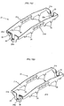
- Fig. 8 and Fig. 9 show a battery positioning structure according to another embodiment of the invention. This embodiment differs from the foregoing embodiment in that the belts 22 are not used.
- the same battery positioning structure is applied to the battery units 5A to 5L. It is assumed that the battery positioning structure is applied to the battery unit 5A.
- the battery positioning structure includes: a pair of brackets 31 and 32 which are attached to an outer surface 5C of the battery cells 5a and 5b and extend in the travelling direction X of the electric vehicle; and check plates 34 and 35 which are detachably attached to the brackets 31 and 32, and include folds 34a and 35a to be engaged with the bolts 23a and 23b.
- the brackets 31 and 32 are attached to the battery unit 5A and the check plates 34 and 35 are attached to the brackets 31 and 32, the battery cells 5a and 5b are made integral with the brackets 31 and 32.
- the brackets 31 and 32 are made of metal, and have their four sides folded.
- the bracket 31 has its one side shaped not to come into contact with the terminals 210 of the battery module 5A.
- the brackets 31 and 32 respectively include bolts 36 and 37 at their opposite ends 31a and 31b, and 32a and 32b, to which the check plates 34 and 35 are attached.
- the check plates 34 and 35 are in the shape of letter U, and have folds 34a and 35a. Further, the check plates 34 and 35 have holes 38 and 39 on the opposite ends 34b and 34c and on the opposite ends of 35b and 35c.
- the bolts 36 and 37 are fitted into the holes 38 and 39.
- the check plates 34 and 35 are attached to the brackets 31 and 32, the bolts 36 and 37 are fitted into the holes 38 and 39, and are fastened by nuts 40 and 41.
- the brackets 31 and 32 cover the outer surfaces 5c of the battery cells 5a and 5b, the check plates 34 and 35 are temporally attached to the brackets 31 and 32 using the nuts 40 and 41, the bolts 23a and 23b are fitted into the folds 34a and 35a and are fastened, and the nuts 40 and 41 are firmly fitted into the bolts 36 and 37. In this state, the check plates 34 and 35 are firmly fixed to the brackets 31 and 32.
- the brackets 31 and 32 extend over the outer surfaces 5c of the battery modules 5a and 5b, and serve as one integral unit.
- the check plates 34 and 35 are attached to the brackets 31 and 32 by fitting the bolts 23a and 23b (on the shield plate 7) into the folds 34a and 34b. Even when there is a space between the battery cells or even when the battery cells have different heights, the check plates 34 and 35 are fixed to the brackets 31 and 32 after aligning the folds 34a and 34b and the bolts 23a and 23b. This enables the battery modules 5a and 5b to be efficiently positioned on the vehicle body without applying unnecessary loads to them.
- the brackets 31 and 32 are made of steel plates, and are shaped not to come into contact with the terminals 210 of the battery cells. Therefore, even when the battery modules 5a and 5b are moved due to crash energy applied to the vehicle body, the brackets 31 and 32 protect them by their rigidity, and do not come into contact with the terminals 210 of the battery modules 5a and 5b.
- the brackets 31 and 32 can reliably position the battery unit 5 on the vehicle body, and protect it against energy applied by the crash.
- the invention is applicable battery positioning structures which can reliably fix battery modules even if there are spaces between them or they have different heights.
Landscapes
- Engineering & Computer Science (AREA)
- Chemical & Material Sciences (AREA)
- Chemical Kinetics & Catalysis (AREA)
- Electrochemistry (AREA)
- General Chemical & Material Sciences (AREA)
- Mechanical Engineering (AREA)
- Transportation (AREA)
- Power Engineering (AREA)
- Sustainable Energy (AREA)
- Sustainable Development (AREA)
- Life Sciences & Earth Sciences (AREA)
- Aviation & Aerospace Engineering (AREA)
- Combustion & Propulsion (AREA)
- Battery Mounting, Suspending (AREA)
- Arrangement Or Mounting Of Propulsion Units For Vehicles (AREA)
- Electric Propulsion And Braking For Vehicles (AREA)
Applications Claiming Priority (3)
| Application Number | Priority Date | Filing Date | Title |
|---|---|---|---|
| JP2007256477A JP5040566B2 (ja) | 2007-09-28 | 2007-09-28 | 電気自動車のバッテリー固定構造 |
| EP08738688.4A EP2080656B1 (fr) | 2007-09-28 | 2008-03-14 | Structure de verrouillage des batteries de véhicule électrique |
| PCT/JP2008/055183 WO2009041090A1 (fr) | 2007-09-28 | 2008-03-14 | Structure de verrouillage des batteries de véhicule électrique |
Related Parent Applications (2)
| Application Number | Title | Priority Date | Filing Date |
|---|---|---|---|
| EP08738688.4A Division-Into EP2080656B1 (fr) | 2007-09-28 | 2008-03-14 | Structure de verrouillage des batteries de véhicule électrique |
| EP08738688.4A Division EP2080656B1 (fr) | 2007-09-28 | 2008-03-14 | Structure de verrouillage des batteries de véhicule électrique |
Publications (2)
| Publication Number | Publication Date |
|---|---|
| EP3205523A1 true EP3205523A1 (fr) | 2017-08-16 |
| EP3205523B1 EP3205523B1 (fr) | 2019-07-24 |
Family
ID=40510994
Family Applications (2)
| Application Number | Title | Priority Date | Filing Date |
|---|---|---|---|
| EP08738688.4A Ceased EP2080656B1 (fr) | 2007-09-28 | 2008-03-14 | Structure de verrouillage des batteries de véhicule électrique |
| EP17159346.0A Ceased EP3205523B1 (fr) | 2007-09-28 | 2008-03-14 | Structure de positionnement de batterie de véhicule électrique |
Family Applications Before (1)
| Application Number | Title | Priority Date | Filing Date |
|---|---|---|---|
| EP08738688.4A Ceased EP2080656B1 (fr) | 2007-09-28 | 2008-03-14 | Structure de verrouillage des batteries de véhicule électrique |
Country Status (5)
| Country | Link |
|---|---|
| US (2) | US8091669B2 (fr) |
| EP (2) | EP2080656B1 (fr) |
| JP (1) | JP5040566B2 (fr) |
| CN (1) | CN101610928B (fr) |
| WO (1) | WO2009041090A1 (fr) |
Families Citing this family (62)
| Publication number | Priority date | Publication date | Assignee | Title |
|---|---|---|---|---|
| US8006626B2 (en) * | 2007-05-07 | 2011-08-30 | General Electric Company | System and method for cooling a battery |
| JP5040566B2 (ja) * | 2007-09-28 | 2012-10-03 | 三菱自動車工業株式会社 | 電気自動車のバッテリー固定構造 |
| JP4630367B2 (ja) * | 2008-11-25 | 2011-02-09 | 本田技研工業株式会社 | 車両用高圧電装ユニット |
| JP2010272520A (ja) * | 2009-04-24 | 2010-12-02 | Nissan Motor Co Ltd | 組電池 |
| JP5163593B2 (ja) * | 2009-05-25 | 2013-03-13 | コベルコ建機株式会社 | ハイブリッド作業機械 |
| JP5504977B2 (ja) * | 2010-03-02 | 2014-05-28 | 株式会社オートネットワーク技術研究所 | 電池接続アセンブリ |
| CN103401275A (zh) * | 2010-11-26 | 2013-11-20 | 刘卉 | 车辆供电系统和方法、电源、安装装置及电源转接装置 |
| US20120161472A1 (en) | 2010-12-22 | 2012-06-28 | Tesla Motors, Inc. | System for Absorbing and Distributing Side Impact Energy Utilizing an Integrated Battery Pack |
| US8336658B2 (en) * | 2010-12-22 | 2012-12-25 | Tesla Motors, Inc. | Augmented vehicle seat mount |
| US8875828B2 (en) | 2010-12-22 | 2014-11-04 | Tesla Motors, Inc. | Vehicle battery pack thermal barrier |
| US8702161B2 (en) | 2010-12-22 | 2014-04-22 | Tesla Motors, Inc. | System for absorbing and distributing side impact energy utilizing an integrated battery pack and side sill assembly |
| US8833499B2 (en) * | 2010-12-22 | 2014-09-16 | Tesla Motors, Inc. | Integration system for a vehicle battery pack |
| DE102010056261B4 (de) * | 2010-12-24 | 2025-06-26 | Audi Ag | Vorrichtung zum Halten einer Batterie in einer Fahrzeugkarosserie |
| US9108497B2 (en) * | 2011-06-13 | 2015-08-18 | Albert W. Harrison, III | Structural enclosure for packaging power electronics for vehicle battery modules and methods of servicing and manufacturing vehicles using same |
| JP5141795B2 (ja) * | 2011-06-20 | 2013-02-13 | 株式会社豊田自動織機 | 車両用バッテリユニット装着装置 |
| CN102290545B (zh) * | 2011-07-15 | 2014-01-22 | 奇瑞汽车股份有限公司 | 一种电池固定支架 |
| FR2978382B1 (fr) * | 2011-07-29 | 2014-11-07 | Renault Sa | Dispositif de fixation d'un groupe motopropulseur sur un chassis d'un vehicule automobile |
| US20140220391A1 (en) * | 2011-08-26 | 2014-08-07 | Sanyo Electric Co., Ltd., | Power source apparatus, and vehicle and power storage device equipped with that power source apparatus |
| DE102011112572A1 (de) * | 2011-09-08 | 2013-03-14 | GM Global Technology Operations LLC (n. d. Gesetzen des Staates Delaware) | Auswechselbares Batteriemodul für ein Elektrofahrzeug |
| CN102427116B (zh) * | 2011-11-18 | 2013-10-30 | 重庆长安汽车股份有限公司 | 一种汽车电池模组 |
| JP5664542B2 (ja) * | 2011-12-23 | 2015-02-04 | 株式会社デンソー | 電池パック |
| US20130284747A1 (en) * | 2012-04-27 | 2013-10-31 | Anthony M. Rund | Fluid tank and mounting configuration |
| JP6016080B2 (ja) * | 2012-07-17 | 2016-10-26 | 三菱自動車工業株式会社 | 電池モジュールの支持構造 |
| TWI486268B (zh) * | 2012-08-22 | 2015-06-01 | Kwang Yang Motor Co | Battery fixing device for electric locomotive |
| CA2926291C (fr) | 2012-10-19 | 2022-04-05 | Chris FORSBERG | Systemes et procedes d'installation d'un systeme d'alimentation en carburant |
| FR3001185B1 (fr) * | 2013-01-24 | 2015-03-06 | Courb | Vehicule terrestre et procede de fabrication d'un tel vehicule |
| EP2999413A4 (fr) | 2013-05-20 | 2017-09-13 | Medrobotics Corporation | Instruments chirurgicaux articules et procédé de déploiement associe |
| US9540849B2 (en) * | 2013-09-27 | 2017-01-10 | Cecil W. Renfro | Commercial motor vehicle and heavy equipment battery locking device and system for use |
| US10033022B2 (en) | 2014-09-30 | 2018-07-24 | Johnson Controls Technology Company | Battery module retention structure |
| WO2016072286A1 (fr) * | 2014-11-07 | 2016-05-12 | 本田技研工業株式会社 | Véhicule |
| US9758030B2 (en) | 2016-02-09 | 2017-09-12 | NextEv USA, Inc. | Replaceable battery assembly having a latching mechanism |
| US10017037B2 (en) | 2016-02-09 | 2018-07-10 | Nio Usa, Inc. | Vehicle having a battery pack directly attached to the cross rails of a frame structure |
| JP6619665B2 (ja) * | 2016-02-12 | 2019-12-11 | 本田技研工業株式会社 | 外部給電機 |
| JP6551791B2 (ja) * | 2016-02-29 | 2019-07-31 | 本田技研工業株式会社 | バッテリ支持構造 |
| US10632857B2 (en) | 2016-08-17 | 2020-04-28 | Shape Corp. | Battery support and protection structure for a vehicle |
| CN106275348A (zh) * | 2016-08-31 | 2017-01-04 | 安徽远东船舶有限公司 | 一种纯电动船舶液体电池组固定装置 |
| US10549620B2 (en) * | 2016-09-07 | 2020-02-04 | Thunder Power Electric Vehicle Limited | Profiles in the floor section |
| JP6631472B2 (ja) * | 2016-11-07 | 2020-01-15 | トヨタ自動車株式会社 | 車両下部構造 |
| CN110383526A (zh) | 2017-01-04 | 2019-10-25 | 形状集团 | 节点模块化的车辆电池托盘结构 |
| JP2018113153A (ja) * | 2017-01-11 | 2018-07-19 | トヨタ自動車株式会社 | 電池パック |
| US10483510B2 (en) | 2017-05-16 | 2019-11-19 | Shape Corp. | Polarized battery tray for a vehicle |
| US10886513B2 (en) | 2017-05-16 | 2021-01-05 | Shape Corp. | Vehicle battery tray having tub-based integration |
| WO2018213383A1 (fr) | 2017-05-16 | 2018-11-22 | Shape Corp. | Support de batterie de véhicule à 'éléments de retenue et de support de batterie intégrés |
| CN111108015A (zh) | 2017-09-13 | 2020-05-05 | 形状集团 | 具有管状外围壁的车辆电池托盘 |
| US12347879B2 (en) | 2017-09-13 | 2025-07-01 | Shape Corp. | Vehicle battery tray with tubular peripheral wall |
| CN207257348U (zh) * | 2017-09-15 | 2018-04-20 | 爱驰汽车有限公司 | 车身框架及具有该车身框架的汽车 |
| WO2019071013A1 (fr) | 2017-10-04 | 2019-04-11 | Shape Corp. | Ensemble fond de bac support de batterie pour véhicules électriques |
| US11183726B2 (en) * | 2017-12-15 | 2021-11-23 | Tiveni Mergeco, Inc. | Clamping bar holder component for a battery module and method thereof |
| EP3759761B1 (fr) | 2018-03-01 | 2026-04-08 | Shape Corp. | Système de refroidissement intégré à un bac de batterie de véhicule |
| US11688910B2 (en) | 2018-03-15 | 2023-06-27 | Shape Corp. | Vehicle battery tray having tub-based component |
| CA3110459C (fr) | 2018-08-24 | 2024-06-18 | Hexagon Purus North America Holdings Inc. | Systeme de batterie pour vehicules utilitaires lourds |
| JP7293752B2 (ja) * | 2019-03-15 | 2023-06-20 | スズキ株式会社 | 車両用電装部品被覆構造 |
| WO2020215023A1 (fr) | 2019-04-19 | 2020-10-22 | Hexagon Purus North America Holdings Inc. | Ensemble de dispositifs accessoires d'extrémité avant électrique |
| US11040610B2 (en) | 2019-04-19 | 2021-06-22 | Hexagon Purus North America Holdings Inc. | Electric powertrain system for heavy duty vehicles |
| CA3161967C (fr) | 2019-11-26 | 2025-05-13 | Hexagon Purus North America Holdings Inc. | Distribution de puissance pour véhicule électrique et module de commande de moteur |
| MX2022008267A (es) | 2020-01-03 | 2022-08-04 | Tesla Inc | Extraccion selectiva de litio a partir de minerales de arcilla. |
| CN121469274A (zh) * | 2020-01-21 | 2026-02-06 | 麦格纳国际公司 | 用于汽车的框架组件 |
| US11926207B2 (en) | 2020-10-09 | 2024-03-12 | Hexagon Purus North America Holdings Inc. | Battery and auxiliary components for vehicle trailer |
| CA3205080A1 (fr) | 2020-12-11 | 2022-06-16 | Hexagon Purus North America Holdings Inc. | Systemes et procedes d'attenuation de rupture d'attelage de remorque |
| JP2022111787A (ja) * | 2021-01-20 | 2022-08-01 | 本田技研工業株式会社 | 車両搭載用電池パック |
| KR102893182B1 (ko) * | 2021-08-27 | 2025-11-28 | 컨템포러리 엠퍼렉스 테크놀로지 (홍콩) 리미티드 | 배터리의 박스, 배터리, 브래킷 및 전기 장치 |
| FR3154041B1 (fr) * | 2023-10-11 | 2025-08-29 | Psa Automobiles Sa | Vehicule comportant deux structures de fixation aptes a maintenir une batterie electrique |
Citations (4)
| Publication number | Priority date | Publication date | Assignee | Title |
|---|---|---|---|---|
| US2783293A (en) * | 1955-12-22 | 1957-02-26 | Brode Milling Co Inc Van | Storage battery mountings |
| US3061662A (en) * | 1959-07-01 | 1962-10-30 | Electro Acid Corp | Electric storage battery |
| JP3050010B2 (ja) | 1993-09-02 | 2000-06-05 | 日産自動車株式会社 | 電気自動車のバッテリ固定構造 |
| US20040053128A1 (en) * | 2002-09-13 | 2004-03-18 | Smith Donald G. | Battery cover assembly |
Family Cites Families (115)
| Publication number | Priority date | Publication date | Assignee | Title |
|---|---|---|---|---|
| US541864A (en) * | 1895-07-02 | Harry t | ||
| US3125177A (en) * | 1964-03-17 | Battery clamping device | ||
| US842389A (en) * | 1904-02-27 | 1907-01-29 | Decker Electrical Mfg Company | Battery. |
| US1338690A (en) * | 1920-02-27 | 1920-05-04 | Thomas L Moorman | Battery-box |
| US1661779A (en) * | 1923-06-27 | 1928-03-06 | Commercial Truck Company | Battery cradle for electric trucks |
| US1607908A (en) * | 1926-04-30 | 1926-11-23 | Menser A Nelson | Battery holder |
| US1650527A (en) * | 1926-11-30 | 1927-11-22 | Seward Trunk And Bag Company | Trunk carrier for automobiles |
| US1677789A (en) * | 1927-08-06 | 1928-07-17 | Clinton L Mabey | Battery-box clamp |
| US1734645A (en) * | 1928-04-16 | 1929-11-05 | Bruno A Polland | Battery-box holddown |
| US1952150A (en) * | 1930-05-02 | 1934-03-27 | William H Trimble | Cradle for storage batteries |
| US1982957A (en) * | 1930-11-01 | 1934-12-04 | All Steel Equip Company | Outlet box and hanger bar |
| US2022595A (en) * | 1932-12-19 | 1935-11-26 | Gowing Nathan Howard | Battery protector |
| US2216663A (en) * | 1939-11-03 | 1940-10-01 | Arnold B Fogle | Storage battery box clamp |
| US2326481A (en) * | 1941-07-21 | 1943-08-10 | Harvey E Meyer | Battery hold-down |
| US2415284A (en) * | 1944-05-22 | 1947-02-04 | Holman William | Battery hold-down device |
| US2833363A (en) * | 1955-10-07 | 1958-05-06 | Gen Motors Corp | Retainer means for batteries and the like |
| US2994395A (en) * | 1958-12-05 | 1961-08-01 | Theodore W Hall | Battery clamp |
| US3105567A (en) * | 1960-09-16 | 1963-10-01 | Jr Earl K Schultz | Battery and clamp protector |
| US3167458A (en) * | 1961-10-20 | 1965-01-26 | Brazell William Allen | Storage battery case |
| US3165163A (en) * | 1962-05-24 | 1965-01-12 | Ford Motor Co | Battery mounting device |
| US3167148A (en) * | 1963-06-17 | 1965-01-26 | Ford Motor Co | Battery hold down clamp |
| FR1600393A (fr) * | 1968-12-31 | 1970-07-20 | ||
| US3557895A (en) * | 1969-01-24 | 1971-01-26 | Frank W Thomas | Battery securing means |
| US3866704A (en) * | 1973-02-08 | 1975-02-18 | East Penn Manufacturing Compan | Battery holddown |
| US3904439A (en) * | 1974-07-11 | 1975-09-09 | Jr James H Barrett | Safety and locked spark proof battery box |
| US4020244A (en) * | 1975-02-18 | 1977-04-26 | Motorola, Inc. | Clamping structure for battery cells |
| US3961988A (en) * | 1975-04-28 | 1976-06-08 | Andreoff Gerald F | Battery cover |
| DE2543308C3 (de) * | 1975-09-27 | 1979-12-20 | Daimler-Benz Ag, 7000 Stuttgart | Vorrichtung zur Aufnahme einer Akkumulatorenbatterie |
| US4077485A (en) * | 1975-12-31 | 1978-03-07 | Bolt Vehicles, Incorporated | Vehicle battery mounting apparatus |
| FR2344133A1 (fr) * | 1976-03-09 | 1977-10-07 | Accumulateurs Fixes | Chassis pour batterie d'accumulateurs |
| US4033424A (en) * | 1976-04-09 | 1977-07-05 | Towmotor Corporation | Article hold-down device |
| US4054730A (en) * | 1976-07-19 | 1977-10-18 | Salvatore Crifasi | Winter power saver |
| GB1537108A (en) * | 1976-08-20 | 1978-12-29 | Chloride Group Ltd | Cell racks for holding electric cells |
| WO1980001896A1 (fr) * | 1979-03-16 | 1980-09-18 | Towmotor Corp | Dispositif de retenue de batteries reglable |
| US4367572A (en) * | 1980-06-19 | 1983-01-11 | Zielenski Anthony L | Elastic clamping apparatus |
| US4317497A (en) * | 1980-07-28 | 1982-03-02 | General Motors Corporation | Battery tray for electric vehicle |
| US4495787A (en) * | 1983-01-24 | 1985-01-29 | Comstock Harold N | Locking means for battery, etc. |
| US4520887A (en) * | 1983-02-04 | 1985-06-04 | D & S Plug Corporation | Battery holddown arrangement |
| US4508794A (en) * | 1984-01-25 | 1985-04-02 | Wright Anthony A | Security battery holder |
| JPS60156053U (ja) * | 1984-03-28 | 1985-10-17 | 日産自動車株式会社 | 自動車バツテリの取付構造 |
| JPS61116769A (ja) * | 1984-11-12 | 1986-06-04 | Sanyo Electric Co Ltd | 燃料電池のスタツク枠体締付装置 |
| JPS63106157A (ja) * | 1986-10-23 | 1988-05-11 | Nissan Motor Co Ltd | 自動車のバツテリ組付方法 |
| US4723618A (en) * | 1987-03-02 | 1988-02-09 | Deere & Company | Swing-out battery box |
| US4819955A (en) * | 1987-05-19 | 1989-04-11 | Incorporated Tank Systems, Inc. | Mobile storage tank battery |
| FR2627630B1 (fr) * | 1988-02-22 | 1990-06-08 | Accumulateurs Fixes | Chassis support pour elements d'accumulateurs |
| US4936409A (en) * | 1989-08-14 | 1990-06-26 | Nix Charles D | Battery hold down device |
| US5004081A (en) * | 1989-12-20 | 1991-04-02 | Caterpillar Inc. | Battery restraint system |
| US5140744A (en) * | 1990-06-06 | 1992-08-25 | Miller Robert D | Modular multicell battery and rack |
| US5052198A (en) * | 1990-07-30 | 1991-10-01 | Elektrek Partnership | Battery lock and hold-down device |
| US5197559A (en) * | 1990-09-04 | 1993-03-30 | Fortress Life-Style, Inc. | Foldable wheelchair with optional power or manual drive |
| US5379184A (en) * | 1991-08-30 | 1995-01-03 | Unisys Corporation | Pry-in/pry-out disk drive receptacle |
| US5390754A (en) * | 1992-01-16 | 1995-02-21 | Honda Giken Kogyo Kabushiki Kaisha | Battery box for an electric vehicle |
| US5222711A (en) * | 1992-01-27 | 1993-06-29 | Bell Stuart D | Battery hold-down |
| JP3350189B2 (ja) * | 1993-04-30 | 2002-11-25 | 本田技研工業株式会社 | 電気自動車用バッテリボックス装置 |
| US5377947A (en) * | 1993-08-23 | 1995-01-03 | Johnson; Jerome | Battery holddown |
| US5547160A (en) * | 1993-08-23 | 1996-08-20 | Quick Cable Corporation | Battery holddown |
| FI92808C (fi) * | 1993-12-14 | 1995-01-10 | Imatran Voima Oy | Sähköauton akuston käyttö- ja käsittelyjärjestelmä |
| US5522734A (en) * | 1994-04-15 | 1996-06-04 | Invacare Corporation | Apparatus for interconnecting wheelchair batteries |
| US5536595A (en) * | 1994-09-30 | 1996-07-16 | Globe-Union Inc. | Split shell battery enclosure |
| US6085854A (en) * | 1994-12-13 | 2000-07-11 | Nissan Motor Co., Ltd. | Battery frame structure for electric motorcar |
| US5543248A (en) * | 1995-02-17 | 1996-08-06 | Globe-Union Inc. | Thermal stabilization shield for storage batteries |
| JPH08250151A (ja) * | 1995-03-14 | 1996-09-27 | Matsushita Electric Ind Co Ltd | 密閉形アルカリ蓄電池の単位電池 |
| US5709280A (en) * | 1995-10-13 | 1998-01-20 | Gnb Technologies, Inc. | Sealed lead-acid cell tray assembly and motive powered vehicle using such cell tray assembly |
| JP3271494B2 (ja) * | 1995-10-24 | 2002-04-02 | 松下電器産業株式会社 | 積層密閉形アルカリ蓄電池 |
| US5987936A (en) * | 1996-12-06 | 1999-11-23 | Hartman, Jr.; Charles William | Hinged securing member |
| US6145612A (en) * | 1997-10-06 | 2000-11-14 | Sunrise Medical Hhg Inc. | Removable battery case with locking mechanism for a powered wheelchair |
| US6102356A (en) * | 1998-03-02 | 2000-08-15 | Huntley; William F. | Battery retainer |
| US6189635B1 (en) * | 1998-03-09 | 2001-02-20 | Navistar International Transportation Corp. | Polyurethane/polyurea elastomer coated steel battery box for hybrid electric vehicle applications |
| US6224998B1 (en) * | 1999-02-04 | 2001-05-01 | Delphi Technologies, Inc. | Battery, tray and heat shield assembly |
| JP2000301954A (ja) * | 1999-04-16 | 2000-10-31 | Shin Kobe Electric Mach Co Ltd | 車両用電池 |
| US6138483A (en) * | 1999-05-11 | 2000-10-31 | Cnc Atlas Manufacturing Inc. | Anti-theft device for office equipment |
| JP4259694B2 (ja) * | 1999-09-29 | 2009-04-30 | 富士重工業株式会社 | 車両用バッテリの搭載構造 |
| US7128999B1 (en) * | 2000-03-13 | 2006-10-31 | General Motors Corporation | System of retaining a plurality of batteries for an electric/hybrid vehicle |
| JP2002020555A (ja) * | 2000-07-06 | 2002-01-23 | Sakamoto Yakuhin Kogyo Co Ltd | 食品包装用防曇性フィルム |
| JP3776300B2 (ja) * | 2000-09-11 | 2006-05-17 | 本田技研工業株式会社 | 燃料電池スタック |
| US6521371B1 (en) * | 2000-11-28 | 2003-02-18 | Richard A. Lavanture | Battery tray |
| JP2002205556A (ja) * | 2001-01-05 | 2002-07-23 | Suzuki Motor Corp | 車両のバッテリ固定構造 |
| JP2002205555A (ja) * | 2001-01-12 | 2002-07-23 | Suzuki Motor Corp | 車両のバッテリ固定構造 |
| JP4672892B2 (ja) * | 2001-03-30 | 2011-04-20 | 本田技研工業株式会社 | 燃料電池スタック |
| TW469824U (en) * | 2001-05-23 | 2001-12-21 | Merits Health Products Co Ltd | Battery placement structure for electric wheelchair |
| DE10230635A1 (de) * | 2002-07-08 | 2004-01-29 | Adam Opel Ag | Befestigungsvorrichtung für Behälter |
| JP3754016B2 (ja) * | 2002-10-16 | 2006-03-08 | 川崎重工業株式会社 | 車両のバッテリー取付構造 |
| US7332243B2 (en) * | 2003-01-09 | 2008-02-19 | Johnson Controls Technology Company | Battery and battery container |
| US6871829B2 (en) * | 2003-01-23 | 2005-03-29 | Quick Cable Corporation | Telescopically adjustable battery holddown |
| US7323271B2 (en) * | 2003-08-27 | 2008-01-29 | Kim Manufacturing Company | Front access battery tray apparatus and system |
| JP2005132272A (ja) * | 2003-10-31 | 2005-05-26 | Hino Motors Ltd | バッテリカバーの押え構造 |
| US7384704B2 (en) * | 2003-12-18 | 2008-06-10 | General Motors Corporation | Methods and apparatus for controlling the temperature of an automobile battery |
| JP4485187B2 (ja) * | 2003-12-24 | 2010-06-16 | 本田技研工業株式会社 | バッテリケース |
| JP3934110B2 (ja) * | 2004-01-22 | 2007-06-20 | 本田技研工業株式会社 | 燃料電池の車両搭載構造 |
| JP4448703B2 (ja) * | 2004-01-30 | 2010-04-14 | 本田技研工業株式会社 | 車載用燃料電池スタックの運転方法 |
| JP2005297754A (ja) * | 2004-04-12 | 2005-10-27 | Nissan Motor Co Ltd | 車両用側方部品の支持構造 |
| JP2005324643A (ja) * | 2004-05-13 | 2005-11-24 | Toyota Industries Corp | バッテリストッパー |
| US7507499B2 (en) * | 2004-05-24 | 2009-03-24 | General Motors Corporation | Battery pack arrangements |
| JP4359200B2 (ja) * | 2004-07-23 | 2009-11-04 | 三洋電機株式会社 | 車両用の電源装置 |
| JP2006123658A (ja) * | 2004-10-27 | 2006-05-18 | Mitsubishi Fuso Truck & Bus Corp | 車両の電子機器取付構造 |
| JP5113319B2 (ja) * | 2004-10-29 | 2013-01-09 | 富士重工業株式会社 | 蓄電体セルのパッケージ構造 |
| JP4670382B2 (ja) * | 2005-02-16 | 2011-04-13 | トヨタ自動車株式会社 | 電池パックおよび自動車 |
| JP2006236826A (ja) | 2005-02-25 | 2006-09-07 | Toyota Motor Corp | 電池パック |
| JP5070681B2 (ja) * | 2005-04-07 | 2012-11-14 | 日産自動車株式会社 | 組電池 |
| US7641017B2 (en) * | 2005-06-02 | 2010-01-05 | Honda Motor Co., Ltd. | Fuel cell vehicle |
| US20070042263A1 (en) * | 2005-08-18 | 2007-02-22 | Balash Gary M | Single cell module system |
| JP4660328B2 (ja) * | 2005-09-15 | 2011-03-30 | 三洋電機株式会社 | 電源装置 |
| US7270208B2 (en) * | 2005-12-30 | 2007-09-18 | Taiwan An I Co., Ltd. | Battery carrier sliding device of an electrical wheel chair |
| JP5141026B2 (ja) * | 2006-02-27 | 2013-02-13 | トヨタ自動車株式会社 | 蓄電パックの車載構造 |
| JP4989920B2 (ja) * | 2006-05-31 | 2012-08-01 | 三洋電機株式会社 | 電池パック |
| US7913786B2 (en) * | 2006-09-29 | 2011-03-29 | Honda Motor Co., Ltd. | Battery mounting system |
| CN101159339A (zh) * | 2006-10-08 | 2008-04-09 | 郑玉民 | 电动车用标准通用电池模组 |
| JP5254568B2 (ja) * | 2007-05-16 | 2013-08-07 | 日立ビークルエナジー株式会社 | セルコントローラ、電池モジュールおよび電源システム |
| US7836989B2 (en) * | 2007-06-26 | 2010-11-23 | Honda Motor Company, Ltd. | Battery boxes and vehicles including same |
| JP5040566B2 (ja) * | 2007-09-28 | 2012-10-03 | 三菱自動車工業株式会社 | 電気自動車のバッテリー固定構造 |
| US7559392B2 (en) * | 2007-10-16 | 2009-07-14 | International Truck Intellectual Property Company, Llc | Electric cable organizer for a battery box in an automotive vehicle |
| JP2009161138A (ja) * | 2008-01-10 | 2009-07-23 | Yamaha Motor Co Ltd | 自動二輪車の電源支持機構及びそれを備えた自動二輪車 |
| JP5340659B2 (ja) * | 2008-07-07 | 2013-11-13 | 三洋電機株式会社 | 車両用の組電池 |
| USD611413S1 (en) * | 2009-06-17 | 2010-03-09 | Camco Manufacturing Inc. | Battery hold down tray |
| US20110165451A1 (en) * | 2010-01-05 | 2011-07-07 | Myung-Chul Kim | Battery pack |
-
2007
- 2007-09-28 JP JP2007256477A patent/JP5040566B2/ja not_active Expired - Fee Related
-
2008
- 2008-03-14 CN CN2008800011704A patent/CN101610928B/zh not_active Expired - Fee Related
- 2008-03-14 WO PCT/JP2008/055183 patent/WO2009041090A1/fr not_active Ceased
- 2008-03-14 EP EP08738688.4A patent/EP2080656B1/fr not_active Ceased
- 2008-03-14 US US12/445,407 patent/US8091669B2/en not_active Expired - Fee Related
- 2008-03-14 EP EP17159346.0A patent/EP3205523B1/fr not_active Ceased
-
2011
- 2011-12-07 US US13/314,094 patent/US8312952B2/en not_active Expired - Fee Related
Patent Citations (4)
| Publication number | Priority date | Publication date | Assignee | Title |
|---|---|---|---|---|
| US2783293A (en) * | 1955-12-22 | 1957-02-26 | Brode Milling Co Inc Van | Storage battery mountings |
| US3061662A (en) * | 1959-07-01 | 1962-10-30 | Electro Acid Corp | Electric storage battery |
| JP3050010B2 (ja) | 1993-09-02 | 2000-06-05 | 日産自動車株式会社 | 電気自動車のバッテリ固定構造 |
| US20040053128A1 (en) * | 2002-09-13 | 2004-03-18 | Smith Donald G. | Battery cover assembly |
Also Published As
| Publication number | Publication date |
|---|---|
| EP2080656B1 (fr) | 2018-11-07 |
| US8312952B2 (en) | 2012-11-20 |
| JP2009083673A (ja) | 2009-04-23 |
| CN101610928B (zh) | 2012-09-26 |
| US8091669B2 (en) | 2012-01-10 |
| US20120073888A1 (en) | 2012-03-29 |
| CN101610928A (zh) | 2009-12-23 |
| WO2009041090A1 (fr) | 2009-04-02 |
| EP3205523B1 (fr) | 2019-07-24 |
| JP5040566B2 (ja) | 2012-10-03 |
| EP2080656A1 (fr) | 2009-07-22 |
| US20100175940A1 (en) | 2010-07-15 |
| EP2080656A4 (fr) | 2016-09-07 |
Similar Documents
| Publication | Publication Date | Title |
|---|---|---|
| EP2080656B1 (fr) | Structure de verrouillage des batteries de véhicule électrique | |
| EP2357104B1 (fr) | Structure de refroidissement d'unité de source de puissance de véhicule | |
| US7079379B2 (en) | Cooling device high voltage electrical unit for motor of vehicle, and hybrid vehicle | |
| US8584779B2 (en) | Structure for mounting power source apparatus | |
| US8251169B2 (en) | Temperature adjustment structure for power storage apparatus | |
| US10759262B2 (en) | Battery pack | |
| EP2691999B1 (fr) | Module de batterie comprenant un boîtier externe et un revêtement | |
| JP6016080B2 (ja) | 電池モジュールの支持構造 | |
| CN101389501A (zh) | 蓄电箱的车载构造 | |
| JP2006236826A (ja) | 電池パック | |
| US20230072733A1 (en) | Battery module and battery pack including battery modules | |
| US20250192342A1 (en) | Thermal management valves for controlling battery cell vent byproducts within traction battery packs | |
| EP4366060A1 (fr) | Bloc-batterie de véhicule et camion électrique | |
| CN111081922A (zh) | 蓄电单元和蓄电装置 | |
| US11289761B2 (en) | Battery unit | |
| KR20140045572A (ko) | 조전지 | |
| EP4571938A1 (fr) | Module de batterie, bloc-batterie et véhicule | |
| US20250210750A1 (en) | Battery module, a battery pack, and a vehicle | |
| JP5360239B2 (ja) | 電気自動車のバッテリー固定構造 | |
| US20250158189A1 (en) | Battery module pair | |
| EP4557455A1 (fr) | Agencement de module de batterie, bloc-batterie et véhicule | |
| JP2020140938A (ja) | 車両 | |
| WO2025151110A1 (fr) | Structure de montage de boîtier pour dispositif électronique de puissance | |
| CN108666487B (zh) | 用于电池系统的容纳设备 | |
| CN122000586A (zh) | 电池包和车辆 |
Legal Events
| Date | Code | Title | Description |
|---|---|---|---|
| PUAI | Public reference made under article 153(3) epc to a published international application that has entered the european phase |
Free format text: ORIGINAL CODE: 0009012 |
|
| AC | Divisional application: reference to earlier application |
Ref document number: 2080656 Country of ref document: EP Kind code of ref document: P |
|
| AK | Designated contracting states |
Kind code of ref document: A1 Designated state(s): DE FR GB |
|
| 17P | Request for examination filed |
Effective date: 20180214 |
|
| RBV | Designated contracting states (corrected) |
Designated state(s): DE FR GB |
|
| 17Q | First examination report despatched |
Effective date: 20180810 |
|
| REG | Reference to a national code |
Ref country code: DE Ref legal event code: R079 Ref document number: 602008060771 Country of ref document: DE Free format text: PREVIOUS MAIN CLASS: B60K0001040000 Ipc: H01M0002100000 |
|
| GRAP | Despatch of communication of intention to grant a patent |
Free format text: ORIGINAL CODE: EPIDOSNIGR1 |
|
| RIC1 | Information provided on ipc code assigned before grant |
Ipc: H01M 2/10 20060101AFI20190116BHEP |
|
| INTG | Intention to grant announced |
Effective date: 20190218 |
|
| GRAA | (expected) grant |
Free format text: ORIGINAL CODE: 0009210 |
|
| RAP1 | Party data changed (applicant data changed or rights of an application transferred) |
Owner name: MITSUBISHI JIDOSHA KOGYO KABUSHIKI KAISHA Owner name: MITSUBISHI JIDOSHA ENGINEERING KABUSHIKI KAISHA |
|
| AC | Divisional application: reference to earlier application |
Ref document number: 2080656 Country of ref document: EP Kind code of ref document: P |
|
| AK | Designated contracting states |
Kind code of ref document: B1 Designated state(s): DE FR GB |
|
| REG | Reference to a national code |
Ref country code: GB Ref legal event code: FG4D |
|
| RIN1 | Information on inventor provided before grant (corrected) |
Inventor name: TANEDA, RYOJI Inventor name: SUZUKI, HIROYASU Inventor name: TOZUKA, YUJI |
|
| REG | Reference to a national code |
Ref country code: DE Ref legal event code: R096 Ref document number: 602008060771 Country of ref document: DE |
|
| REG | Reference to a national code |
Ref country code: DE Ref legal event code: R097 Ref document number: 602008060771 Country of ref document: DE |
|
| PLBE | No opposition filed within time limit |
Free format text: ORIGINAL CODE: 0009261 |
|
| STAA | Information on the status of an ep patent application or granted ep patent |
Free format text: STATUS: NO OPPOSITION FILED WITHIN TIME LIMIT |
|
| 26N | No opposition filed |
Effective date: 20200603 |
|
| REG | Reference to a national code |
Ref country code: DE Ref legal event code: R079 Ref document number: 602008060771 Country of ref document: DE Free format text: PREVIOUS MAIN CLASS: H01M0002100000 Ipc: H01M0050200000 |
|
| PGFP | Annual fee paid to national office [announced via postgrant information from national office to epo] |
Ref country code: FR Payment date: 20210210 Year of fee payment: 14 |
|
| PGFP | Annual fee paid to national office [announced via postgrant information from national office to epo] |
Ref country code: DE Payment date: 20210302 Year of fee payment: 14 Ref country code: GB Payment date: 20210308 Year of fee payment: 14 |
|
| REG | Reference to a national code |
Ref country code: DE Ref legal event code: R119 Ref document number: 602008060771 Country of ref document: DE |
|
| GBPC | Gb: european patent ceased through non-payment of renewal fee |
Effective date: 20220314 |
|
| PG25 | Lapsed in a contracting state [announced via postgrant information from national office to epo] |
Ref country code: GB Free format text: LAPSE BECAUSE OF NON-PAYMENT OF DUE FEES Effective date: 20220314 Ref country code: FR Free format text: LAPSE BECAUSE OF NON-PAYMENT OF DUE FEES Effective date: 20220331 Ref country code: DE Free format text: LAPSE BECAUSE OF NON-PAYMENT OF DUE FEES Effective date: 20221001 |