EP3205784B1 - Skelettbauvorrichtung und fassade, in die eine solche vorrichtung integriert ist - Google Patents
Skelettbauvorrichtung und fassade, in die eine solche vorrichtung integriert ist Download PDFInfo
- Publication number
- EP3205784B1 EP3205784B1 EP17155352.2A EP17155352A EP3205784B1 EP 3205784 B1 EP3205784 B1 EP 3205784B1 EP 17155352 A EP17155352 A EP 17155352A EP 3205784 B1 EP3205784 B1 EP 3205784B1
- Authority
- EP
- European Patent Office
- Prior art keywords
- profile
- posts
- floor
- profiles
- support
- Prior art date
- Legal status (The legal status is an assumption and is not a legal conclusion. Google has not performed a legal analysis and makes no representation as to the accuracy of the status listed.)
- Active
Links
Images


Classifications
-
- E—FIXED CONSTRUCTIONS
- E04—BUILDING
- E04B—GENERAL BUILDING CONSTRUCTIONS; WALLS, e.g. PARTITIONS; ROOFS; FLOORS; CEILINGS; INSULATION OR OTHER PROTECTION OF BUILDINGS
- E04B1/00—Constructions in general; Structures which are not restricted either to walls, e.g. partitions, or floors or ceilings or roofs
- E04B1/18—Structures comprising elongated load-supporting parts, e.g. columns, girders, skeletons
- E04B1/185—Connections not covered by E04B1/21 and E04B1/2403, e.g. connections between structural parts of different material
-
- E—FIXED CONSTRUCTIONS
- E04—BUILDING
- E04B—GENERAL BUILDING CONSTRUCTIONS; WALLS, e.g. PARTITIONS; ROOFS; FLOORS; CEILINGS; INSULATION OR OTHER PROTECTION OF BUILDINGS
- E04B1/00—Constructions in general; Structures which are not restricted either to walls, e.g. partitions, or floors or ceilings or roofs
- E04B1/16—Structures made from masses, e.g. of concrete, cast or similarly formed in situ with or without making use of additional elements, such as permanent forms, substructures to be coated with load-bearing material
- E04B1/161—Structures made from masses, e.g. of concrete, cast or similarly formed in situ with or without making use of additional elements, such as permanent forms, substructures to be coated with load-bearing material with vertical and horizontal slabs, both being partially cast in situ
-
- E—FIXED CONSTRUCTIONS
- E04—BUILDING
- E04B—GENERAL BUILDING CONSTRUCTIONS; WALLS, e.g. PARTITIONS; ROOFS; FLOORS; CEILINGS; INSULATION OR OTHER PROTECTION OF BUILDINGS
- E04B1/00—Constructions in general; Structures which are not restricted either to walls, e.g. partitions, or floors or ceilings or roofs
- E04B1/18—Structures comprising elongated load-supporting parts, e.g. columns, girders, skeletons
- E04B1/30—Structures comprising elongated load-supporting parts, e.g. columns, girders, skeletons the supporting parts being composed of two or more materials; Composite steel and concrete constructions
-
- E—FIXED CONSTRUCTIONS
- E04—BUILDING
- E04B—GENERAL BUILDING CONSTRUCTIONS; WALLS, e.g. PARTITIONS; ROOFS; FLOORS; CEILINGS; INSULATION OR OTHER PROTECTION OF BUILDINGS
- E04B1/00—Constructions in general; Structures which are not restricted either to walls, e.g. partitions, or floors or ceilings or roofs
- E04B1/18—Structures comprising elongated load-supporting parts, e.g. columns, girders, skeletons
- E04B1/24—Structures comprising elongated load-supporting parts, e.g. columns, girders, skeletons the supporting parts consisting of metal
- E04B2001/2466—Details of the elongated load-supporting parts
- E04B2001/2478—Profile filled with concrete
-
- E—FIXED CONSTRUCTIONS
- E04—BUILDING
- E04B—GENERAL BUILDING CONSTRUCTIONS; WALLS, e.g. PARTITIONS; ROOFS; FLOORS; CEILINGS; INSULATION OR OTHER PROTECTION OF BUILDINGS
- E04B5/00—Floors; Floor construction with regard to insulation; Connections specially adapted therefor
- E04B5/16—Load-carrying floor structures wholly or partly cast or similarly formed in situ
- E04B5/17—Floor structures partly formed in situ
- E04B2005/173—Floor structures partly formed in situ with permanent forms for the floor edges
-
- E—FIXED CONSTRUCTIONS
- E04—BUILDING
- E04B—GENERAL BUILDING CONSTRUCTIONS; WALLS, e.g. PARTITIONS; ROOFS; FLOORS; CEILINGS; INSULATION OR OTHER PROTECTION OF BUILDINGS
- E04B5/00—Floors; Floor construction with regard to insulation; Connections specially adapted therefor
- E04B5/16—Load-carrying floor structures wholly or partly cast or similarly formed in situ
- E04B5/17—Floor structures partly formed in situ
- E04B2005/176—Floor structures partly formed in situ with peripheral anchors or supports
-
- E—FIXED CONSTRUCTIONS
- E04—BUILDING
- E04B—GENERAL BUILDING CONSTRUCTIONS; WALLS, e.g. PARTITIONS; ROOFS; FLOORS; CEILINGS; INSULATION OR OTHER PROTECTION OF BUILDINGS
- E04B5/00—Floors; Floor construction with regard to insulation; Connections specially adapted therefor
- E04B5/16—Load-carrying floor structures wholly or partly cast or similarly formed in situ
- E04B5/17—Floor structures partly formed in situ
- E04B5/23—Floor structures partly formed in situ with stiffening ribs or other beam-like formations wholly or partly prefabricated
-
- E—FIXED CONSTRUCTIONS
- E04—BUILDING
- E04C—STRUCTURAL ELEMENTS; BUILDING MATERIALS
- E04C3/00—Structural elongated elements designed for load-supporting
- E04C3/02—Joists; Girders, trusses, or trusslike structures, e.g. prefabricated; Lintels; Transoms; Braces
- E04C3/20—Joists; Girders, trusses, or trusslike structures, e.g. prefabricated; Lintels; Transoms; Braces of concrete or other stone-like material, e.g. with reinforcements or tensioning members
-
- E—FIXED CONSTRUCTIONS
- E04—BUILDING
- E04C—STRUCTURAL ELEMENTS; BUILDING MATERIALS
- E04C3/00—Structural elongated elements designed for load-supporting
- E04C3/30—Columns; Pillars; Struts
- E04C3/34—Columns; Pillars; Struts of concrete other stone-like material, with or without permanent form elements, with or without internal or external reinforcement, e.g. metal coverings
-
- E—FIXED CONSTRUCTIONS
- E04—BUILDING
- E04C—STRUCTURAL ELEMENTS; BUILDING MATERIALS
- E04C3/00—Structural elongated elements designed for load-supporting
- E04C3/30—Columns; Pillars; Struts
- E04C3/36—Columns; Pillars; Struts of materials not covered by groups E04C3/32 or E04C3/34; of a combination of two or more materials
Definitions
- the invention relates to a construction device for the building, and the implementation of which makes it possible to produce a framework for the construction of a building facade and assistance with the production and with the floor support.
- the device of the invention relates to all types of building, tertiary, collective housing, industrial buildings, integration with floating buildings of the ocean liners type, etc.
- the invention relates to a construction framework device which makes it possible to produce a facade with high energy performance, while minimizing thermal bridges.
- Each profile comprises a rear flat surface for bearing on at least one floor nosing, a flat front surface for supporting and fixing the facade elements, and a central flat surface connecting the rear and front flat surfaces.
- the rear and front planar surfaces are in planes parallel to the main plane of the facade, and the median planar surface in a vertical plane perpendicular to said facade plane.
- the section of the profiles can be of various shapes, such as in H, C, U or Z (two branches close to the Z being perpendicular), or according to other specific geometries.
- the construction assembly of the aforementioned patent makes it possible, thanks to the profiles of composite material, to make facade cladding in a simple, rapid manner while eliminating thermal bridges.
- this set is suitable for constructions whose floors are already existing. Indeed, the profiles are fixed by their opposite ends on the one hand to a high floor nose and on the other hand to a low floor nose.
- the object of the invention is therefore to propose a device and a system for carrying construction, for forming walls and facades of buildings, this system making it possible to gain speed of construction and advantageously making it possible to constitute means for supporting and carrying out a floor.
- the system of the invention is prefabricated.
- the load-bearing device and construction framework or load-bearing post and construction framework is defined by the characteristics of claim 1.
- the tube constitutes a reservation means for the introduction of a reinforcement and the pouring concrete so as to constitute a reinforced concrete post and constitute a load-bearing element of a future building construction, while the profile in composite material constitutes a spacer between the facade and exterior cladding of the construction and the interior of construction.
- the profile and the tube form an integral assembly which is hereinafter called a post.
- the post of the invention realizes, once in place and after pouring the concrete, a structural support element (via the tube), while having the function of framework element / support for facade cladding (via the profile ), the profile eliminating the thermal bridges between the exterior and the interior of the construction.
- the profile and the tube are, according to a first variant, manufactured separately and assembled.
- the profile and the tube are produced in a single piece, in one piece.
- Profile means an element of which at least one dimension is very significantly greater than the other two. The element extends in length.
- the profile of the device has a height equivalent to a minimum floor, that is to say a height intended to separate the lower floor from one floor to the upper floor.
- the profile is made of composite material.
- composite material relating to an element in the following description, the manufacture of this element from one or more composite materials.
- the tube when manufactured separately from the profile, is made of any rigid material, such as composite material or steel, or rigid plastic material, or rigid cardboard, or made of a combination of the aforementioned materials (for example made of an internal envelope in a material and an external envelope of another material).
- the composite material element is preferably produced by pultrusion.
- the composite material is made of a matrix at least of a plastic, thermoplastic or thermosetting material, and preferably fire resistant such as those used on the basis of flame retardant acrylic or polyester resin, and reinforcing fibers, in particular glass. , basalt, or even of plant origin.
- the reinforcing fibers are in the form of sheets, mats, fabrics and / or long fibers. Their arrangement between layers of reinforcements is particularly important to jointly improve the mechanical performance and not to increase the cost too much.
- the hollow tube is made integral with the profile by mechanical means such as by riveting, bolting, gluing, or even by heat welding.
- the tube preferably has a square section, or a rectangular or circular section, or any other polygonal geometry. Its section will in particular be determined according to the expected strength requirement for each post made up of the post profile, reinforced concrete being intended to be included in the hollow volume of the tube.
- the core of the profile has at its two opposite distal ends, a respective recess so that the core has a first part called the short part, and a second part called the projecting part, the tube being of length equivalent to the part short of the soul and united with it.
- the projecting part is intended to be applied against the nose of a slab of a construction floor, while the tube is intended to rest on the upper face of the slab.
- the invention also relates to a bearing and framework system comprising several posts each made of a profile and tube, and one or more individual profiles of composite material, the posts and individual profiles being spaced apart and extending longitudinally parallel to each other.
- the system comprising at least two crosspieces, called lower crosspiece and upper crosspiece, preferably made of steel, extending perpendicular to the individual posts and profiles and each of which is assembled respectively at one of the two opposite ends of the individual posts and profiles , preferably the system forming a prefabricated monobloc assembly, ready for installation.
- the invention therefore also relates to an assembly of several posts.
- the individual profiles are of identical or different cross-section to the constituent profiles of the posts, the individual profiles comprising at least one part forming a spacer such as a core and a so-called fixing part, such as at least one wing transverse to the core.
- the individual profiles like the profiles of the posts comprise at least one surface or wing transverse to the core which is intended to be facing the outside of the construction to serve as a surface for fixing to a facade cladding, the core constituting a spacer between the facade cladding and the building floor.
- the number of individual profiles and posts is adapted according to the expressed needs of lowering of load between stages (and therefore of the necessary sections of posts).
- the system comprises for a portion of a construction side, two end posts and three individual intermediate profiles.
- the system comprising the posts and the crosspieces, and possibly the individual profiles, thus forms once in place / associated with the floor of a construction a monobloc carrying system and framework for on the one hand adding a floor in stage, the posts being load-bearing elements, and on the other hand adding a facade, the sections of the posts and individual sections forming the means for supporting the facade.
- the posts and crosspieces, and individual profiles when present are preferably assembled in the factory to form a one-piece system ready for installation.
- the lower cross-member of the system comprises lights of dimensions adapted to cooperate by engagement with the tubes, and lugs making it possible to fix, preferably by riveting, said lower cross-member to the webs of the sections of the posts and of the individual sections they are present.
- the cross-member comprises openings of dimensions equal to the section of a tube, and located directly above the upper openings of the post tubes.
- the invention also relates to the use of at least one load-bearing system and framework of the invention in a building construction, characterized in that the system constitutes a load-bearing means of an upper floor, and links at least two levels of floors between them by reinforced concrete, the concrete of the upper floor being poured into the tubes of the system posts.
- the system of the invention makes it possible to resolve the problems and fire resistance of facade structures in a construction.
- additional profiles of composite material and of smaller section can be added to the fixing parts of the individual profiles and of the pole profiles, the additional profiles serving as means of support and fixing of the facing cladding. construction exterior.
- the invention also relates to a building construction assembly comprising at least one load-bearing and framework system according to the invention, characterized in that the system is installed on a floor provided with reinforcements projecting vertically relative to the floor, the system being positioned so that the tubes are fitted around the reinforcements and the lower cross member resting on the floor. Concrete is poured into the tubes to the floor.
- the assembly includes internal reinforcements arranged in the tubes of the posts, and protrude at the upper end of the tubes; concrete is poured into the tubes to the floor.
- the internal reinforcements cooperate with reinforcement of beams arranged on the upper cross member and extending perpendicular to the longitudinal assemblies, the beams resting on the upper cross member and being intended to carry an upper floor comprising the poured concrete which is housed at the level of the entanglement of the reinforcements of the beams and the reinforcements of the tubes.
- the load-bearing and frame assembly includes a facade covering which is fitted against the load-bearing and frame system.
- the facade cladding is attached to the post profiles and individual profiles, and intended to be in contact with the outside of the building.
- the facade cladding is directly associated with the profiles made of composite material (or even tubes if they are made of composite material), thus avoiding any thermal bridge, an essential aim of the post and of the system of the invention.
- the assembly includes thermal insulation means, preferably in the form of panels, which are housed the successive sections of the posts and individual sections.
- the insulation means can be pre-assembled in the workshop, provided with their rain and vapor barrier, or even with the exterior cladding of the facade and the carpentry also pre-assembled, in the form of prefabricated modules.
- the internal reinforcements are intended to cooperate (become entangled) with reinforcements of beams arranged on the upper cross-member and extending perpendicular to the plane formed by the support and framework system (formed from the plurality of spaced posts and aligned), the beams resting on the upper cross member and being intended to carry an upper floor.
- the upper floor is produced, in a known manner, using beams and slabs, covered in a second step with poured concrete, which is thus accommodated at the level of the entanglement of the reinforcements of the beams and the reinforcements. tubes and descends into the tubes serving as the receiving volume of the concrete.
- the concrete ensures a continuous chaining of reinforced concrete between the two levels, which improves the mechanical performance and fire resistance, and therefore safety.
- length is understood to mean the dimension extending along the longitudinal axis of the profile or the tube of the device.
- width relative to an area of the profile or tube, the transverse dimension and coplanar to the length.
- thermosetting matrix reinforced by glass fibers have a very low expansion almost identical to that of concrete, which allows to associate, fix profiles and tubes to concrete without worrying about the gradient between the coefficients thermal expansion between the two materials.
- the figure 1a illustrates a support and framework device 1A of the invention based on composite material, called a post, and comprising a profile 2 and a tube 3 of composite material, visible in exploded view on the figure 1b .
- the tube 3 is hollow and has its free open ends.
- the tube 3 and the profile 2 can be manufactured separately or be produced in one piece, in particular when they are made of the same material.
- the Figures 1d and 1e illustrate two variants of one-piece posts made of composite material.
- Profile 2 is systematically made of composite material. The shape of the profile is described below.
- the tube 3 is here made of composite material, it could be made of another rigid material such as steel or the like.
- the device 1A is intended to be used for the production of a load-bearing system and framework 1 for the construction of a wall and of a building facade and of the load-bearing system of concrete building floors.
- a building usually comprises a lower floor P1, and upper floors, here two floors P2 and P3, openings 8, thermal insulation panels 9, a facade covering 10 and additional interior panels 9 'of insulation .
- the load-bearing and framework system 1 of the invention makes it possible to constitute the structure of the building for attaching the insulating panels and the facade cladding, and also to constitute the load-bearing system for the upper floors, while avoiding thermal bridges.
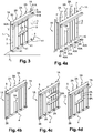
- the figure 3 partially illustrates on one side of the building a load-bearing and framing system 1 of the invention from several type 1A posts, the system being intended to be associated with the concrete floor P1 of the construction and rises from the floor to at the construction height of an upper floor P2 ( figures 2 and 9a ) which forms the upper floor.
- the system 1 makes it possible to constitute not only the framework of the facade by avoiding any thermal bridge between the exterior and the interior, but also the carrying means of the upper floor (thanks to the posts).
- the carrier and framework system 1 of the invention comprises at the base at least two end posts 1A (the post 1A being illustrated in isolation on the figure 1a ). Between the two end posts, depending on the load to be supported, the system has other posts or as shown in the figure 3 usual profiles 2A identical to profiles 2 made of composite material of the posts. In addition, the system comprises two lower 4 and upper 5 crosspieces assembled to the posts and profiles.
- Profiles 2A are usual profiles made of composite material already known for making the façade cladding frames.
- the purpose of the posts 1A is to ensure the load bearing of the upper floor and to allow the façade covering to be fixed, while the sections 2A are intended to fix the façade covering.
- an opening 8 is created in the supporting and framing system 1 as illustrated on the figure 3 .
- the opening 8 is formed from profiles 2A of composite material cut to the appropriate dimensions and assembled vertically and horizontally.
- the frame of the opening 8 thus created via the profiles 2A in composite material constitutes an insulating frame, support for the future carpentry.
- the posts 1A and the sections 2A, including the sections providing the opening 8 can be assembled on site.
- the support and framework system 1 is produced in the factory to constitute a prefabricated monobloc system directly ready to be placed on the floor P1. Its assembly is described later with regard to figures 4a to 4d .
- the level of pre-equipment for the supporting system and framework 1 may be completed directly in the factory and not on site by the insulation means, the networks, the rain and vapor barriers, the facade cladding and the panels interior finish.
- Each post 1A of the invention is therefore formed from the profile 2 and the tube 3 forming a one-piece assembly, the profile and the tube being able to be manufactured separately and assembled or formed in one piece.
- the tube 3 is hollow to receive reinforced concrete so that each post 1A constitutes a load-bearing element of the construction.
- the section 2 of each post 1A is associated with the tube so as to form a projecting part 20 of the tube intended, in the use which is made of the post, to form a spacer, the section further comprising the opposite the tube a surface 21 known as fixing intended for the fixing of a facade cladding.
- the profile 2 has, in the illustrated form variant, a longitudinal core 20 and two longitudinal wings 21 and 22 parallel, spaced and opposite with respect to the core 20.
- the wings 21 and 22 are perpendicular to the core 20 and are oriented in two opposite directions.
- the core 20 thus constitutes the spacer, while the wing 21 constitutes the fixing surface.
- Profile 2 therefore has ( figure 1c ) a section in the general shape of Z according to a top view, the core 20 of the Z being perpendicular to the wings 21 and 22.
- the wings 21 and 22 are of identical width.
- Profile 2 for a post 1A can have various cross-section geometries, several examples of which are illustrated on the variants of Figures 1f to 1 h.
- the profile can only include one core and one transverse wing.
- the profile 2 has a general U-shaped section, the branches 23 and 24 of the U of which are connected by a flat part 25 and terminate in two folded tabs 26 and 27.
- the essential in the shape of the section of the section 2 of a post 1A is that it comprises a part such as the core 20 or the branches 23 and 24 which constitute a spacer between the exterior and the interior of the building. , and at least one transverse part, the wing 21 or the part 25, which constitutes a support and fixing surface for the facade cladding (exterior), the tube 3 being connected either to the core 20 or to the legs 26 and 27.
- the tube 3 has a square section on the side “c”. Its section could present other geometries.
- the figure 1k illustrates a rectangular section.
- the section of the tube 3 is closed line but can also be opened as illustrated on the Figures 1l and 1m , the section being closed by the core 20 of the profile in the associated position of the tube 3 with the profile 2.
- the tube 3 is made from a folded sheet.
- the tube 3 is associated along its entire length with the core 20 of the profile 2 and the wings 22 of said profile opposite the wing 21 intended to accommodate the facade cladding.
- the tube 3 is in intimate contact, one of the corners of the tube being engaged in the inner corner of the profile connecting the core 20 to the wing 22.
- fixing means such as by bolting or riveting, distributed over the length, on the one hand at the level of the core 20 in 6A and on the other hand at the level of the wing 22 in 6B.
- Other assemblies can be envisaged depending on the materials, for example by heat welding.
- the sides of the tube 3 have a dimension "c" greater than the width L of the wings 21 and 22 of the profile 2, and less than the width L 'of the core 20.
- the side c of the tube 3 is equal to half the width L 'of the core 20 of the profile 2.
- the size "c" of the sides of the square section of the tube 3 is for example of the order of 100 to 300 mm.
- the size of the section will be adapted according to the load bearing properties required for the construction.
- the width L of the wings 21 and 22 is for example of the order of 50 to 100mm.
- the width L 'of the core 20 is for example of the order of 200 to 400mm.
- the length (height of the post 1A) of the profile 2 is for example of the order of a floor height, while the tube 3 has a shorter length, for example 2.5 m.
- the core 20 of the profile 2 has at its two opposite upper and lower ends, a respective recess called lower 7 and upper 7 'of the rectangular type.
- Each recess extends over a length L1 in the longitudinal direction of the profile, and over a width corresponding for example to half the width L 'of the core 20.
- the recesses 7 and 7' define protruding parts 28 of the profile 2 with respect to tube 3.
- the recesses 7 and 7 ' are preferably of identical dimensions.
- the recesses 7 and 7 constitute volumes reserved for cooperating with the thickness / the nose of the lower and upper floor slabs when the bearing and framework system is installed.
- the tube 3 has a length suitable for stopping at each step 7 and 7 ′.
- a variant consists in not making any setbacks in the profiles.
- the length of the profile and the tube are identical and their lower end is intended to rest on the lower floor.
- the profiles are combined on the front additional frame of composite material profiles, which connects the profiles of the load-bearing system between two floors.
- the posts 1A and the sections 2 are spaced apart and extend longitudinally parallel to each other, at regular intervals.
- the crosspieces 4 and 5 extend perpendicularly to the sections 2 and are assembled respectively at the opposite upper and lower ends of the sections 2, at the respective recesses 7 and 7 '.
- the crosspieces 4 and 5 are of length Y substantially greater than the distance separating the end posts 1A.
- the length Y is for example of the order of 2.4 to 12m.
- the crosspieces 4 and 5 can be metallic.
- the lower cross member 4 is composed of a main surface 40 which comprises a plurality of openings 40A of dimensions adapted to cooperate by engagement with the section of the tubes 3 of the posts 1A at the level of the recesses 7.
- This lower cross member 4 also includes lugs 41 which rise perpendicularly to the surface 40, tangentially to the webs 20 of the sections 2.
- the legs 41 are of suitable height to allow fixing, such as by riveting, the lower cross member 4 to the cores 20 of the profiles 2, on the face opposite to that on which is fixed the a tube 3, while the projecting parts 28 protrude from the surface 40 of the cross member opposite the tubes 3.
- the width (dimension transverse to the length of the cross member) of the main surface 40 is greater than the side of the square section of a tube 3.
- the upper cross-member 5 is composed of a longitudinal main surface 50, hereinafter called the support surface, and of two longitudinal sides 51A and 51B which are parallel and opposite, and perpendicular to the main surface 50.
- the upper cross member 5 is intended to rest in abutment against the upper recesses 7 ′ of the profiles 2, opposite the cross member 4, and at the level of the upper free end of the tubes 3 of the post profiles 1A.
- the main surface 50 of the upper crossmember 5 nevertheless has at least two recesses 50A and 50B, arranged towards the distal ends.
- the recesses are of equal dimensions to the section of the tubes 3 so that the tubes of the end posts 1A cooperate by interlocking in these recesses, the free end of the tubes opening out at the main surface 50.
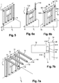
- the tubes 3 of the end posts 1A are intended to accommodate the reinforcements 120 ( Figures 7a and 7b ), called internal reinforcements, the insertion of which is done at the recesses 50A and 50B.
- Each profile 2 is fitted into the respective lumen 40A of the lower cross member 4 and abutted at its lower recess 7.
- the legs 41 are then fixed by riveting to the cores 20, on the face opposite to that fixed to the tubes 3, posts 1A and intermediate sections 2A.
- the upper cross member 5 is pressed against the upper recesses 7 ′ ( figure 4c ) profiles 2, the upper side 51A of the crosspiece abutting the edge of the projecting part 28 of the upper end of each profile 2, while the support surface 50 is fitted onto the tubes 3 of the posts 1A and placed on the upper ends of the intermediate sections 2A.
- the support surface 50 is coplanar with the upper edge of the tubes 3 of the posts 1A, the openings 50A and 50B being perpendicular to the free open ends of the tubes 3 of the posts.
- the width of the upper flank 51A is equal to the length Li of the recess 7 ′ of the upper end.
- the lower flank 51B is pressed against the longitudinal wall of the wing 22 of each profile 2, 2A, intended to be turned towards the interior of the building.
- the width of the lower flank 51B is sufficient to secure the upper cross-member 5, preferably by riveting, against the wing 22 of the sections 2 and 2A ( figure 8b ).
- the supporting and framing system 1 then forms a prefabricated monobloc system which can be installed on the lower floor P1 ( figure 3 ).
- the prefabricated system 1 is raised and brought to the vertical of the floor P1 so as to fit the tubes 3 of the end posts 1A respectively around reinforcement 11 already projecting vertically relative to the floor P1 near the floor nose N and separated a distance corresponding to the distance separating the tubes 3 from the end posts 1A.
- the device is placed on the floor P1, the lower cross member 4 resting on the floor P1 ( figure 3 ), and the projecting part 28 of the core 20 of each profile 2, 2A being pressed against the nose N of the floor ( figures 2 and 9a ).
- the internal reinforcements 11A extend over the entire length of the tubes 3 and protrude from the tubes, without protruding from the cross-member 5 or from the edge of the upper projecting part 28 of the profiles 2 of the posts 1A ( figures 6b ).
- reinforced concrete beams 12 provided with longitudinal reinforcements 11B, are installed transversely to the vertical plane of the system 1 with their distal end resting on the support surface 50 of the upper crossmember 5.
- the opposite distal end beams rests in the same way on a support and framework system 1 of the invention positioned opposite the lower floor P1 vis-à-vis.
- the upper floor P2 is then constructed in a known manner, with the installation of slabs 13 and a trellis 14, then concrete 15 is poured over the entire surface.
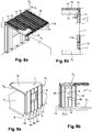
- the figure 8b shows that the concrete 15 propagates along arrow F over the entire upper part, the upper floor P2, and in the tubes 3 of the end posts 1A via the openings 50A and 50B present in the upper crosspiece 5.
- the poured concrete 15 generates the upper floor P2 and secures the framework device 1 in one piece with the lower construction floors P1 and upper P2.
- a second upper floor P3 can be installed on a second carrier and prefabricated framework system 1 of the invention, associated with the upper floor P2 ( figure 2 ).
- the load-bearing and framework system 1 ensures, in addition to the load transfer of the upper floors, the construction of building facades by serving as support for the exterior elements of the facade and for the insulation and interior cladding elements.
- FIGS 9a, 9b and 10 illustrate insulating panels 9 attached to the outside of the framework device 1.
- the panels are slid respectively between the cores 20 of the sections 2 of the posts and intermediate sections 2A consecutive, and wedged by the wings 21 of the sections.
- the panels 9 extend in a vertical plane perpendicular to the webs 20 of the profiles and parallel to the wings 21 arranged on the outside of the facade.
- the panels are usually associated with a rain and vapor barrier.
- FIG. 9a and 9b additional 9 'insulating panels are housed on the interior side of the construction between the core 20 of the profiles 2 and the tube 3 and the core 20 of the consecutive intermediate profiles 2.
- the inner wings 22 of the profiles 2 and 2A make it possible to fix an interior coating 16 such as plasterboard.
- a vapor barrier device 17 can be arranged between the interior insulation panels 9 ′ and the interior covering 16.
- the arrangement of the various elements can be carried out in the factory, the prefabricated support and framework systems 1 then being equipped with these elements when delivered on site.
- the prefabricated construction system of the invention makes it possible to produce a facade acting as a complete wall of the "mantle wall" type without thermal bridge.
- it provides a load-bearing means for producing the upper floor of the construction and constitutes means for integrating the thermal insulation means into the construction.
- the construction system of the invention reduces the overall cost of construction and provides, among other things, speed of implementation and construction with ecological performance (energy performance, low gray energy, low carbon footprint).
Landscapes
- Engineering & Computer Science (AREA)
- Architecture (AREA)
- Physics & Mathematics (AREA)
- Electromagnetism (AREA)
- Civil Engineering (AREA)
- Structural Engineering (AREA)
- Building Environments (AREA)
- Load-Bearing And Curtain Walls (AREA)
Claims (14)
- Träger- und Skelettbauvorrichtung oder Träger- und Skelettbaustütze (1A), ein Profil (2) aus Verbundwerkstoff beinhaltend, das einen Steg (20) umfasst, der ein Distanzstück und mindestens ein sogenanntes Befestigungsteil (21; 25) senkrecht zu dem Teil bildet, welches das Distanzstück bildet, wobei die Vorrichtung weiter mindestens ein, an seinen beiden Enden offenes, hohles Rohr (3) beinhaltet, das im Bereich des Teils, welches das Distanzstück bildet, fest mit dem Profil verbunden ist, wobei das hohle Rohr (3) ein Reservierungsmittel zum Gießen von Beton bildet, wobei der Verbundwerkstoff aus einer Matrix mindestens aus einem Kunststoffmaterial, thermoplastisch oder wärmehärtend, und aus Verstärkungsfasern, im Speziellen aus Glas, Basalt, oder gar pflanzlichen Ursprungs besteht, dadurch gekennzeichnet, dass der Steg (20) des Profils (2) an seinen beiden gegenüberliegenden oberen und unteren Enden eine rechteckige untere (7) und obere (7') Ausnehmung beinhaltet, wobei sich jede Ausnehmung über eine Länge (L1) in der Längsrichtung des Profils (2) und über eine Breite erstreckt, die beispielsweise der Hälfte der Breite (L') des Stegs (20) entspricht, wobei diese Ausnehmungen (7, 7') hervorstehende Teile (28) des Profils (2) in Bezug auf das hohle Rohr (3) definieren.
- Trägervorrichtung oder -stütze nach Anspruch 1, dadurch gekennzeichnet, dass das Rohr (3) und das Profil (2) durch mechanische Mittel, wie durch eine Nietverbindung, eine Bolzenverbindung oder aber durch Wärmeschweißung zusammengesetzt sind, oder aber das Rohr (3) und das Profil (2) aus einem einzelnen Stück gebildet sind.
- Trägervorrichtung oder -stütze nach Anspruch 1 oder 2, dadurch gekennzeichnet, dass das Rohr (3) aus einem Verbundwerkstoff oder aus Stahl oder aus einem steifen Kunststoffmaterial oder aus einem steifen Karton ist oder aus einer Kombination der zuvor genannten Werkstoffe gefertigt ist.
- Trägervorrichtung oder -stütze nach einem der vorstehenden Ansprüche, dadurch gekennzeichnet, dass das Profil (2) einen Querschnitt in Z, L, U, H, Omega aufweist.
- Träger- und Skelettbausystem (1), dadurch gekennzeichnet, dass es mehrere Trägervorrichtungen und - stützen (1A) nach einem der vorstehenden Ansprüche, und eventuell ein oder mehrere Einzelprofile (2A) aus Verbundwerkstoff beinhaltet, wobei die Trägervorrichtungen oder -stützen und Einzelprofile beabstandet sind und sich längsgerichtet parallel zueinander erstrecken, und dadurch, dass es mindestens zwei Traversen (4, 5), untere Traverse und obere Traverse genannt, vorzugsweise aus Stahl beinhaltet, die sich senkrecht zu den Trägervorrichtungen oder -stützen (1A) und Einzelprofilen (2A) erstrecken, und von denen jede (4, 5) jeweils an dem einen der beiden entgegengesetzten Enden der Stützen (1A) und Einzelprofile (2A) zusammengesetzt ist, wobei das System vorzugsweise eine vorgefertigte, einbaubereite Einheit aus einem Stück bildet.
- System nach dem vorstehenden Anspruch, dadurch gekennzeichnet, dass die Traverse (4) Langlöcher (40A) in Abmessungen beinhaltet, die angepasst sind, um durch Eingreifen mit den Rohren (3) zusammenzuwirken, und Laschen (41), die es ermöglichen, die untere Traverse (4) vorzugsweise durch Nietverbindung an Profilen der Trägervorrichtungen oder -stützen (1A) und der Einzelprofile (2A) zu befestigen.
- System nach dem vorstehenden Anspruch, dadurch gekennzeichnet, dass die Traverse (5) Langlöcher (50A, 50B) in Abmessungen beinhaltet, die gleich dem Querschnitt eines Rohres (3) sind, und die sich auf Höhe der oberen Öffnungen der Rohre (3) der Trägervorrichtungen oder - stützen befinden.
- Verwendung mindestens eines Träger- und Skelettbausystems (1) nach einem der Ansprüche 5 bis 7, bei einer Konstruktion eines Gebäudes, dadurch gekennzeichnet, dass das System ein Trägermittel für einen oberen Fußboden bildet, und mindestens zwei Fußbodenniveaus zwischen einander durch Stahlbeton verbindet, wobei der Beton des oberen Fußbodens in die Rohre (3) der Trägerstützen (1A) des Systems gegossen wird.
- Verwendung nach dem vorstehenden Anspruch, dadurch gekennzeichnet, dass je nach Typs des Einzelprofils und des Profils der Trägervorrichtungen oder -stützen zusätzliche Profile aus Verbundwerkstoff und mit kleinerem Querschnitt zu den Befestigungsteilen der Einzelprofile und der Profile der Trägervorrichtungen oder -stützen hinzugefügt werden, wobei die zusätzlichen Profile als Träger- und Befestigungsmittel für Fassadenverkleidung an der Außenseite der Konstruktion dienen.
- Einheit zur Gebäudekonstruktion, mindestens ein Träger- und Skelettbausystem (1) nach einem der Ansprüche 5 bis 7 beinhaltend, dadurch gekennzeichnet, dass das System auf einem Fußboden (P1) installiert ist, der mit Bewehrungen (11) versehen ist, die in Bezug auf den Fußboden vertikal hervorstehen, wobei das System derart positioniert ist, dass die Rohre (3) um die Bewehrungen (11) und die untere Traverse (4), die auf dem Fußboden (P1) aufliegen, eingepasst sind.
- Einheit nach dem vorstehenden Anspruch, dadurch gekennzeichnet, dass Beton (15) bis zum Fußboden (P1) in die Rohre (3) gegossen wird.
- Einheit nach dem vorstehenden Anspruch, dadurch gekennzeichnet, dass sie innere Bewehrungen (11A) beinhaltet, die in den Rohren (3) der Stützen (1A) angeordnet sind, und am oberen Ende der Rohre hervorstehen, und dadurch, dass die inneren Bewehrungen (11A) mit den Bewehrungen (11B) von Trägern (12) zusammenwirken, die auf der oberen Traverse (5) angeordnet sind, und sich senkrecht zu den Längseinheiten erstrecken, wobei die Träger auf der oberen Traverse (5) aufliegen, und dazu bestimmt sind, einen oberen Fußboden (P2) zu tragen, der den gegossenen Beton (15) umfasst, der im Bereich der Verflechtung der Bewehrungen der Träger und der Bewehrungen der Rohre aufgenommen ist.
- Einheit nach einem der Ansprüche 10 bis 12, dadurch gekennzeichnet, dass sie einen Fassadenüberzug (10) beinhaltet, der an dem Träger- und Skelettbausystem (1) beigebracht wird.
- Einheit nach einem der Ansprüche 10 bis 13, dadurch gekennzeichnet, dass sie Mittel zur Wärmeisolierung, vorzugsweise in Form von Platten, beinhaltet, die zwischen den aufeinanderfolgenden Profilen (2, 2A) aufgenommen sind, wobei Mittel zur Isolierung in der Werkstatt, mit ihrer Regensperre und Dampfsperre, sogar mit ihrem Fassadenaußenüberzug versehen, und mit den ebenfalls vormontierten Fenstern und Türen in Form von vorgefertigten Modulen vormontiert sein können.
Applications Claiming Priority (1)
| Application Number | Priority Date | Filing Date | Title |
|---|---|---|---|
| FR1651178A FR3047755B1 (fr) | 2016-02-12 | 2016-02-12 | Dispositif d’ossature de construction et facade integrant un tel dispositif |
Publications (2)
| Publication Number | Publication Date |
|---|---|
| EP3205784A1 EP3205784A1 (de) | 2017-08-16 |
| EP3205784B1 true EP3205784B1 (de) | 2020-07-01 |
Family
ID=56069060
Family Applications (1)
| Application Number | Title | Priority Date | Filing Date |
|---|---|---|---|
| EP17155352.2A Active EP3205784B1 (de) | 2016-02-12 | 2017-02-09 | Skelettbauvorrichtung und fassade, in die eine solche vorrichtung integriert ist |
Country Status (2)
| Country | Link |
|---|---|
| EP (1) | EP3205784B1 (de) |
| FR (1) | FR3047755B1 (de) |
Families Citing this family (2)
| Publication number | Priority date | Publication date | Assignee | Title |
|---|---|---|---|---|
| CN111255081B (zh) * | 2020-03-03 | 2024-09-13 | 北京仲基应用技术研究院有限公司 | 快装钢结构及太阳能多功能式建筑及安装方法 |
| CN111571753A (zh) * | 2020-06-05 | 2020-08-25 | 溧阳二十八所系统装备有限公司 | 高载荷系固件及其安装方法 |
Citations (1)
| Publication number | Priority date | Publication date | Assignee | Title |
|---|---|---|---|---|
| US6123485A (en) * | 1998-02-03 | 2000-09-26 | University Of Central Florida | Pre-stressed FRP-concrete composite structural members |
Family Cites Families (3)
| Publication number | Priority date | Publication date | Assignee | Title |
|---|---|---|---|---|
| CA2234313A1 (en) * | 1997-04-07 | 1998-10-07 | Joseph A. Charlson | Composite insulated framing members and envelope extension system for buildings |
| US6158190A (en) * | 1999-03-29 | 2000-12-12 | East Ohio Machinery | Insulated composite steel member |
| CN204691076U (zh) * | 2015-05-07 | 2015-10-07 | 天津大学 | L形装配式组合异形柱 |
-
2016
- 2016-02-12 FR FR1651178A patent/FR3047755B1/fr active Active
-
2017
- 2017-02-09 EP EP17155352.2A patent/EP3205784B1/de active Active
Patent Citations (1)
| Publication number | Priority date | Publication date | Assignee | Title |
|---|---|---|---|---|
| US6123485A (en) * | 1998-02-03 | 2000-09-26 | University Of Central Florida | Pre-stressed FRP-concrete composite structural members |
Also Published As
| Publication number | Publication date |
|---|---|
| EP3205784A1 (de) | 2017-08-16 |
| FR3047755B1 (fr) | 2020-07-24 |
| FR3047755A1 (fr) | 2017-08-18 |
Similar Documents
| Publication | Publication Date | Title |
|---|---|---|
| EP2971389B1 (de) | Modulares bausystem | |
| EP2347057B1 (de) | Modulares konstruktionssystem | |
| CA2802585C (fr) | Element de construction modulaire prefabrique pour la realisation de mur | |
| EP4194631A1 (de) | Vorgefertigte verbundfassadenplatte und verfahren zur herstellung einer fassade eines gebäudes | |
| EP3205784A1 (de) | Skelettbauvorrichtung und fassade, in die eine solche vorrichtung integriert ist | |
| EP0985071A1 (de) | Gebäudegerüst | |
| EP0152145B1 (de) | Platte für den Bau eines Hauses im Baukastensystem | |
| EP2576933B1 (de) | Kartonbauelement und konstruktionsverfahren unter verwendung solcher elemente | |
| EP4219848B1 (de) | Boden für ein wohnmodul | |
| EP2354346B1 (de) | Bauelement zur Herstellung einer Mauerwand | |
| EP2005011B1 (de) | Ein in einen bestimmten winkel vorgeformtes und durch rücksprünge begrenztes steckelement umfassende eckanordnung | |
| EP2029827A1 (de) | Fertigteilplatte für hochbau und herstellungsverfahren dafür | |
| FR2927340A1 (fr) | Abri leger | |
| EP0320359B1 (de) | Vorrichtung für eine leichte Gebäudefassade | |
| EP0767282A1 (de) | Verbundmetallträger | |
| EP0327531A1 (de) | Selbsttragendes element, metallgerüst und isolierende eindeckung dafür und damit hergestelltes dach. | |
| FR3035892A1 (fr) | Assemblage de poutres et de poteaux pour construction par empilage | |
| EP2339085A1 (de) | Vorgefertigtes Element zum Bau von Gebäudeanbauten, und so erstellte Gebäudeanbauten | |
| EP0085011A1 (de) | Selbsttragende Bauplatte für Innen- und Aussenwände von Gebäuden | |
| FR2962463A1 (fr) | Caisson monobloc pour assemblage d'elements de construction, et methode de construction associee | |
| FR2931492A1 (fr) | Structure porteuse | |
| WO2011061414A1 (fr) | Structure porteuse | |
| EP1783291B1 (de) | Modulare Fassadenkonstruktion | |
| EP4536909A1 (de) | Bauwerk mit doppelrahmen aus beton | |
| EP0365512A1 (de) | Vorgefertigte Bauelemente zur Errichtung von Gebaüden und Bauverfahren zur Errichtung von Gebaüden mittels dieser Bauelemente |
Legal Events
| Date | Code | Title | Description |
|---|---|---|---|
| PUAI | Public reference made under article 153(3) epc to a published international application that has entered the european phase |
Free format text: ORIGINAL CODE: 0009012 |
|
| STAA | Information on the status of an ep patent application or granted ep patent |
Free format text: STATUS: THE APPLICATION HAS BEEN PUBLISHED |
|
| AK | Designated contracting states |
Kind code of ref document: A1 Designated state(s): AL AT BE BG CH CY CZ DE DK EE ES FI FR GB GR HR HU IE IS IT LI LT LU LV MC MK MT NL NO PL PT RO RS SE SI SK SM TR |
|
| AX | Request for extension of the european patent |
Extension state: BA ME |
|
| STAA | Information on the status of an ep patent application or granted ep patent |
Free format text: STATUS: REQUEST FOR EXAMINATION WAS MADE |
|
| 17P | Request for examination filed |
Effective date: 20180213 |
|
| RBV | Designated contracting states (corrected) |
Designated state(s): AL AT BE BG CH CY CZ DE DK EE ES FI FR GB GR HR HU IE IS IT LI LT LU LV MC MK MT NL NO PL PT RO RS SE SI SK SM TR |
|
| REG | Reference to a national code |
Ref country code: DE Ref legal event code: R079 Ref document number: 602017018867 Country of ref document: DE Free format text: PREVIOUS MAIN CLASS: E04B0001180000 Ipc: E04B0001160000 |
|
| STAA | Information on the status of an ep patent application or granted ep patent |
Free format text: STATUS: EXAMINATION IS IN PROGRESS |
|
| RIC1 | Information provided on ipc code assigned before grant |
Ipc: E04C 3/36 20060101ALI20180924BHEP Ipc: E04C 3/20 20060101ALI20180924BHEP Ipc: E04C 3/34 20060101ALI20180924BHEP Ipc: E04B 5/17 20060101ALI20180924BHEP Ipc: E04B 1/30 20060101ALI20180924BHEP Ipc: E04B 5/23 20060101ALI20180924BHEP Ipc: E04B 1/24 20060101ALI20180924BHEP Ipc: E04B 1/16 20060101AFI20180924BHEP Ipc: E04B 1/18 20060101ALI20180924BHEP |
|
| 17Q | First examination report despatched |
Effective date: 20181011 |
|
| GRAP | Despatch of communication of intention to grant a patent |
Free format text: ORIGINAL CODE: EPIDOSNIGR1 |
|
| STAA | Information on the status of an ep patent application or granted ep patent |
Free format text: STATUS: GRANT OF PATENT IS INTENDED |
|
| GRAS | Grant fee paid |
Free format text: ORIGINAL CODE: EPIDOSNIGR3 |
|
| INTG | Intention to grant announced |
Effective date: 20200429 |
|
| GRAA | (expected) grant |
Free format text: ORIGINAL CODE: 0009210 |
|
| STAA | Information on the status of an ep patent application or granted ep patent |
Free format text: STATUS: THE PATENT HAS BEEN GRANTED |
|
| AK | Designated contracting states |
Kind code of ref document: B1 Designated state(s): AL AT BE BG CH CY CZ DE DK EE ES FI FR GB GR HR HU IE IS IT LI LT LU LV MC MK MT NL NO PL PT RO RS SE SI SK SM TR |
|
| REG | Reference to a national code |
Ref country code: AT Ref legal event code: REF Ref document number: 1286310 Country of ref document: AT Kind code of ref document: T Effective date: 20200715 Ref country code: CH Ref legal event code: EP |
|
| REG | Reference to a national code |
Ref country code: IE Ref legal event code: FG4D Free format text: LANGUAGE OF EP DOCUMENT: FRENCH |
|
| REG | Reference to a national code |
Ref country code: DE Ref legal event code: R096 Ref document number: 602017018867 Country of ref document: DE |
|
| REG | Reference to a national code |
Ref country code: LT Ref legal event code: MG4D |
|
| PG25 | Lapsed in a contracting state [announced via postgrant information from national office to epo] |
Ref country code: BG Free format text: LAPSE BECAUSE OF FAILURE TO SUBMIT A TRANSLATION OF THE DESCRIPTION OR TO PAY THE FEE WITHIN THE PRESCRIBED TIME-LIMIT Effective date: 20201001 |
|
| REG | Reference to a national code |
Ref country code: NL Ref legal event code: MP Effective date: 20200701 |
|
| REG | Reference to a national code |
Ref country code: AT Ref legal event code: MK05 Ref document number: 1286310 Country of ref document: AT Kind code of ref document: T Effective date: 20200701 |
|
| PG25 | Lapsed in a contracting state [announced via postgrant information from national office to epo] |
Ref country code: NO Free format text: LAPSE BECAUSE OF FAILURE TO SUBMIT A TRANSLATION OF THE DESCRIPTION OR TO PAY THE FEE WITHIN THE PRESCRIBED TIME-LIMIT Effective date: 20201001 Ref country code: GR Free format text: LAPSE BECAUSE OF FAILURE TO SUBMIT A TRANSLATION OF THE DESCRIPTION OR TO PAY THE FEE WITHIN THE PRESCRIBED TIME-LIMIT Effective date: 20201002 Ref country code: FI Free format text: LAPSE BECAUSE OF FAILURE TO SUBMIT A TRANSLATION OF THE DESCRIPTION OR TO PAY THE FEE WITHIN THE PRESCRIBED TIME-LIMIT Effective date: 20200701 Ref country code: CZ Free format text: LAPSE BECAUSE OF FAILURE TO SUBMIT A TRANSLATION OF THE DESCRIPTION OR TO PAY THE FEE WITHIN THE PRESCRIBED TIME-LIMIT Effective date: 20200701 Ref country code: HR Free format text: LAPSE BECAUSE OF FAILURE TO SUBMIT A TRANSLATION OF THE DESCRIPTION OR TO PAY THE FEE WITHIN THE PRESCRIBED TIME-LIMIT Effective date: 20200701 Ref country code: ES Free format text: LAPSE BECAUSE OF FAILURE TO SUBMIT A TRANSLATION OF THE DESCRIPTION OR TO PAY THE FEE WITHIN THE PRESCRIBED TIME-LIMIT Effective date: 20200701 Ref country code: PT Free format text: LAPSE BECAUSE OF FAILURE TO SUBMIT A TRANSLATION OF THE DESCRIPTION OR TO PAY THE FEE WITHIN THE PRESCRIBED TIME-LIMIT Effective date: 20201102 Ref country code: SE Free format text: LAPSE BECAUSE OF FAILURE TO SUBMIT A TRANSLATION OF THE DESCRIPTION OR TO PAY THE FEE WITHIN THE PRESCRIBED TIME-LIMIT Effective date: 20200701 Ref country code: LT Free format text: LAPSE BECAUSE OF FAILURE TO SUBMIT A TRANSLATION OF THE DESCRIPTION OR TO PAY THE FEE WITHIN THE PRESCRIBED TIME-LIMIT Effective date: 20200701 Ref country code: AT Free format text: LAPSE BECAUSE OF FAILURE TO SUBMIT A TRANSLATION OF THE DESCRIPTION OR TO PAY THE FEE WITHIN THE PRESCRIBED TIME-LIMIT Effective date: 20200701 |
|
| PG25 | Lapsed in a contracting state [announced via postgrant information from national office to epo] |
Ref country code: IS Free format text: LAPSE BECAUSE OF FAILURE TO SUBMIT A TRANSLATION OF THE DESCRIPTION OR TO PAY THE FEE WITHIN THE PRESCRIBED TIME-LIMIT Effective date: 20201101 Ref country code: PL Free format text: LAPSE BECAUSE OF FAILURE TO SUBMIT A TRANSLATION OF THE DESCRIPTION OR TO PAY THE FEE WITHIN THE PRESCRIBED TIME-LIMIT Effective date: 20200701 Ref country code: RS Free format text: LAPSE BECAUSE OF FAILURE TO SUBMIT A TRANSLATION OF THE DESCRIPTION OR TO PAY THE FEE WITHIN THE PRESCRIBED TIME-LIMIT Effective date: 20200701 Ref country code: LV Free format text: LAPSE BECAUSE OF FAILURE TO SUBMIT A TRANSLATION OF THE DESCRIPTION OR TO PAY THE FEE WITHIN THE PRESCRIBED TIME-LIMIT Effective date: 20200701 |
|
| PG25 | Lapsed in a contracting state [announced via postgrant information from national office to epo] |
Ref country code: NL Free format text: LAPSE BECAUSE OF FAILURE TO SUBMIT A TRANSLATION OF THE DESCRIPTION OR TO PAY THE FEE WITHIN THE PRESCRIBED TIME-LIMIT Effective date: 20200701 |
|
| REG | Reference to a national code |
Ref country code: DE Ref legal event code: R097 Ref document number: 602017018867 Country of ref document: DE |
|
| PG25 | Lapsed in a contracting state [announced via postgrant information from national office to epo] |
Ref country code: SM Free format text: LAPSE BECAUSE OF FAILURE TO SUBMIT A TRANSLATION OF THE DESCRIPTION OR TO PAY THE FEE WITHIN THE PRESCRIBED TIME-LIMIT Effective date: 20200701 Ref country code: DK Free format text: LAPSE BECAUSE OF FAILURE TO SUBMIT A TRANSLATION OF THE DESCRIPTION OR TO PAY THE FEE WITHIN THE PRESCRIBED TIME-LIMIT Effective date: 20200701 Ref country code: RO Free format text: LAPSE BECAUSE OF FAILURE TO SUBMIT A TRANSLATION OF THE DESCRIPTION OR TO PAY THE FEE WITHIN THE PRESCRIBED TIME-LIMIT Effective date: 20200701 Ref country code: EE Free format text: LAPSE BECAUSE OF FAILURE TO SUBMIT A TRANSLATION OF THE DESCRIPTION OR TO PAY THE FEE WITHIN THE PRESCRIBED TIME-LIMIT Effective date: 20200701 Ref country code: IT Free format text: LAPSE BECAUSE OF FAILURE TO SUBMIT A TRANSLATION OF THE DESCRIPTION OR TO PAY THE FEE WITHIN THE PRESCRIBED TIME-LIMIT Effective date: 20200701 |
|
| PLBE | No opposition filed within time limit |
Free format text: ORIGINAL CODE: 0009261 |
|
| STAA | Information on the status of an ep patent application or granted ep patent |
Free format text: STATUS: NO OPPOSITION FILED WITHIN TIME LIMIT |
|
| PG25 | Lapsed in a contracting state [announced via postgrant information from national office to epo] |
Ref country code: AL Free format text: LAPSE BECAUSE OF FAILURE TO SUBMIT A TRANSLATION OF THE DESCRIPTION OR TO PAY THE FEE WITHIN THE PRESCRIBED TIME-LIMIT Effective date: 20200701 |
|
| 26N | No opposition filed |
Effective date: 20210406 |
|
| PG25 | Lapsed in a contracting state [announced via postgrant information from national office to epo] |
Ref country code: SK Free format text: LAPSE BECAUSE OF FAILURE TO SUBMIT A TRANSLATION OF THE DESCRIPTION OR TO PAY THE FEE WITHIN THE PRESCRIBED TIME-LIMIT Effective date: 20200701 |
|
| PG25 | Lapsed in a contracting state [announced via postgrant information from national office to epo] |
Ref country code: SI Free format text: LAPSE BECAUSE OF FAILURE TO SUBMIT A TRANSLATION OF THE DESCRIPTION OR TO PAY THE FEE WITHIN THE PRESCRIBED TIME-LIMIT Effective date: 20200701 |
|
| PG25 | Lapsed in a contracting state [announced via postgrant information from national office to epo] |
Ref country code: MC Free format text: LAPSE BECAUSE OF FAILURE TO SUBMIT A TRANSLATION OF THE DESCRIPTION OR TO PAY THE FEE WITHIN THE PRESCRIBED TIME-LIMIT Effective date: 20200701 |
|
| REG | Reference to a national code |
Ref country code: BE Ref legal event code: MM Effective date: 20210228 |
|
| PG25 | Lapsed in a contracting state [announced via postgrant information from national office to epo] |
Ref country code: LU Free format text: LAPSE BECAUSE OF NON-PAYMENT OF DUE FEES Effective date: 20210209 |
|
| PG25 | Lapsed in a contracting state [announced via postgrant information from national office to epo] |
Ref country code: IE Free format text: LAPSE BECAUSE OF NON-PAYMENT OF DUE FEES Effective date: 20210209 |
|
| PG25 | Lapsed in a contracting state [announced via postgrant information from national office to epo] |
Ref country code: BE Free format text: LAPSE BECAUSE OF NON-PAYMENT OF DUE FEES Effective date: 20210228 |
|
| PG25 | Lapsed in a contracting state [announced via postgrant information from national office to epo] |
Ref country code: HU Free format text: LAPSE BECAUSE OF FAILURE TO SUBMIT A TRANSLATION OF THE DESCRIPTION OR TO PAY THE FEE WITHIN THE PRESCRIBED TIME-LIMIT; INVALID AB INITIO Effective date: 20170209 |
|
| PG25 | Lapsed in a contracting state [announced via postgrant information from national office to epo] |
Ref country code: CY Free format text: LAPSE BECAUSE OF FAILURE TO SUBMIT A TRANSLATION OF THE DESCRIPTION OR TO PAY THE FEE WITHIN THE PRESCRIBED TIME-LIMIT Effective date: 20200701 |
|
| P01 | Opt-out of the competence of the unified patent court (upc) registered |
Effective date: 20230530 |
|
| PG25 | Lapsed in a contracting state [announced via postgrant information from national office to epo] |
Ref country code: MK Free format text: LAPSE BECAUSE OF FAILURE TO SUBMIT A TRANSLATION OF THE DESCRIPTION OR TO PAY THE FEE WITHIN THE PRESCRIBED TIME-LIMIT Effective date: 20200701 |
|
| PG25 | Lapsed in a contracting state [announced via postgrant information from national office to epo] |
Ref country code: TR Free format text: LAPSE BECAUSE OF FAILURE TO SUBMIT A TRANSLATION OF THE DESCRIPTION OR TO PAY THE FEE WITHIN THE PRESCRIBED TIME-LIMIT Effective date: 20200701 |
|
| PG25 | Lapsed in a contracting state [announced via postgrant information from national office to epo] |
Ref country code: MT Free format text: LAPSE BECAUSE OF FAILURE TO SUBMIT A TRANSLATION OF THE DESCRIPTION OR TO PAY THE FEE WITHIN THE PRESCRIBED TIME-LIMIT Effective date: 20200701 |
|
| REG | Reference to a national code |
Ref country code: CH Ref legal event code: U11 Free format text: ST27 STATUS EVENT CODE: U-0-0-U10-U11 (AS PROVIDED BY THE NATIONAL OFFICE) Effective date: 20260331 |
|
| PGFP | Annual fee paid to national office [announced via postgrant information from national office to epo] |
Ref country code: GB Payment date: 20260225 Year of fee payment: 10 |
|
| PGFP | Annual fee paid to national office [announced via postgrant information from national office to epo] |
Ref country code: DE Payment date: 20260225 Year of fee payment: 10 |
|
| PGFP | Annual fee paid to national office [announced via postgrant information from national office to epo] |
Ref country code: FR Payment date: 20260223 Year of fee payment: 10 |
|
| PGFP | Annual fee paid to national office [announced via postgrant information from national office to epo] |
Ref country code: CH Payment date: 20260331 Year of fee payment: 10 |