EP3205805A1 - Procede et dispositif de fixation d'un dormant sur une surface interieure - Google Patents
Procede et dispositif de fixation d'un dormant sur une surface interieure Download PDFInfo
- Publication number
- EP3205805A1 EP3205805A1 EP16154973.8A EP16154973A EP3205805A1 EP 3205805 A1 EP3205805 A1 EP 3205805A1 EP 16154973 A EP16154973 A EP 16154973A EP 3205805 A1 EP3205805 A1 EP 3205805A1
- Authority
- EP
- European Patent Office
- Prior art keywords
- fixing device
- screw
- soffit
- frame
- plastic
- Prior art date
- Legal status (The legal status is an assumption and is not a legal conclusion. Google has not performed a legal analysis and makes no representation as to the accuracy of the status listed.)
- Withdrawn
Links
- 238000000034 method Methods 0.000 title claims description 9
- 239000004033 plastic Substances 0.000 claims abstract description 9
- 229920003023 plastic Polymers 0.000 claims abstract description 9
- 239000002184 metal Substances 0.000 claims abstract description 4
- 238000001746 injection moulding Methods 0.000 claims description 2
- 229910000831 Steel Inorganic materials 0.000 description 5
- 238000003780 insertion Methods 0.000 description 5
- 230000037431 insertion Effects 0.000 description 5
- 239000000463 material Substances 0.000 description 5
- 230000002787 reinforcement Effects 0.000 description 5
- 239000010959 steel Substances 0.000 description 5
- 239000011449 brick Substances 0.000 description 4
- 238000009825 accumulation Methods 0.000 description 3
- 230000005540 biological transmission Effects 0.000 description 3
- 238000010079 rubber tapping Methods 0.000 description 3
- 238000004873 anchoring Methods 0.000 description 2
- 230000001419 dependent effect Effects 0.000 description 1
- 239000011152 fibreglass Substances 0.000 description 1
- 230000007774 longterm Effects 0.000 description 1
Images

Classifications
-
- E—FIXED CONSTRUCTIONS
- E06—DOORS, WINDOWS, SHUTTERS, OR ROLLER BLINDS IN GENERAL; LADDERS
- E06B—FIXED OR MOVABLE CLOSURES FOR OPENINGS IN BUILDINGS, VEHICLES, FENCES OR LIKE ENCLOSURES IN GENERAL, e.g. DOORS, WINDOWS, BLINDS, GATES
- E06B1/00—Border constructions of openings in walls, floors, or ceilings; Frames to be rigidly mounted in such openings
- E06B1/56—Fastening frames to the border of openings or to similar contiguous frames
- E06B1/60—Fastening frames to the border of openings or to similar contiguous frames by mechanical means, e.g. anchoring means
- E06B1/6069—Separate spacer means acting exclusively in the plane of the opening; Shims; Wedges; Tightening of a complete frame inside a wall opening
- E06B1/6076—Separate spacer means acting exclusively in the plane of the opening; Shims; Wedges; Tightening of a complete frame inside a wall opening of screw-type
Definitions
- the invention relates to a method and a device for the spaced attachment of a frame to a soffit of a wall by means of a screw and a fixing device.
- Frame of windows and doors are fixed in the opening reveal by a corresponding number of fasteners or devices so that, for example, by wind suction and pressure transmitted to the windows forces are introduced into the masonry, the frame are moved as little as possible relative to the soffit may.
- a mounting device for a window frame in which by means of a screw and an end in a wide foot screw by twisting the sleeve clamping of the frame in the soffit can be achieved.
- a similar device is used in the DE 197 25 95 A1 described.
- fastening devices are complicated and cumbersome to handle.
- the object of the present invention is therefore to provide a method and a device for the spaced attachment of a frame to a soffit by means of screws, so that the transmission of high forces perpendicular to the screw axes in the masonry or the soffit is made possible.
- the invention solves this object by a method according to claim 1 and a fixing device according to claim 5, preferably in conjunction with one or more of the features of the dependent claims.
- the core of the present invention is the use of a fixing device, which is pressed during insertion and / or after the soffit so that the fixing by frictional and / or positive connection perpendicular to the screw axis acting forces from the screw transmits to the soffit and thus movement the screw in the masonry significantly reduced.
- the distance of the frame frame back from the reveal is preferably about 15 to 30 mm circumferentially.
- the inventively used Fixing device is preferably made in one piece of plastic or metal, particularly preferably made of plastic. Suitable plastics are, for example, PVC-U or ABS, which on the one hand have sufficient rigidity and at the same time sufficient elasticity. It can also be used glass fiber reinforced plastics.
- the fixing device used according to the invention preferably has a curved, in particular plate-shaped base body and a central opening or bore with a diameter which is smaller than the outer diameter of the screw.
- the main body is shaped and made so elastic that it acts like a disc spring.
- the pressing of the fixing device to the soffit is preferably carried out by rotation relative to the soffit, so by a corresponding rotational movement.
- the fixing device for centrally a corresponding accumulation of material, in particular in the form of a polygon, most preferably in the form of a hexagon, on, said accumulation of material through the central aperture, in particular a cylindrical hole, is pierced.
- the screw When inserting the screw into this opening, the screw preferably cuts itself a corresponding internal thread in this accumulation of material, so that a fixation of the fixing device is ensured in the axial direction of the screw. At the same time by turning the fixing relative to the soffit, a corresponding pressing against the soffit, so that acting by frictional and / or positive locking perpendicular to the screw axis forces are transmitted from the screw to the soffit.
- the fixing device according to the invention thus combines the action of a lock nut and a plate spring in one-piece design.
- the main body of the fixing device according to the invention is designed in particular substantially rotationally symmetrical and preferably has an outer diameter of between 30 and 70 mm. With appropriate elasticity of the body can sufficiently high forces are transmitted perpendicular to the screw axis of the screw on the soffit.
- the fixing device has a tab projecting radially from the main body to a length of 10 to 30 mm. By means of this tab, the fixing device can be easily held in the correct position during insertion of the screw through the frame in a hole in the soffit, so that the screw meets the central opening of the fixing device.
- the fixing device for easier centering on its upper side facing the frame back has a centering funnel.
- the fixing device on its side facing the soffit in addition to a guide cone, which is inserted into the hole in the soffit and thus allows a centering of the fixing device relative to the soffit.
- the guide cone supports the transmission of forces between the fixing device and the masonry.
- the fixing device By means of the preferred embodiment of the invention on the side facing away from the soffit of the fixing device, in particular centrally arranged polygons, especially hex, the fixing device after screwing the fixing screw by means of a commercially available open-end wrench relative to the fastening screw rotated and thus moved axially in the direction of the soffit and so pressed to the soffit.
- the fixing device is made in one piece from plastic, the achievable thereby axial contact forces due to the relatively large contact surface of the body of the Fixing device to transmit relatively high forces perpendicular to the screw axis on the soffit. This transfer takes place primarily by frictional forces, but can also be supported by positive anchoring of portions of the fixing device according to the invention in superficial grooves or joints of the soffit.
- the fixing device according to the invention for this purpose on its the soffit facing bottom ribs and / or teeth. Due to the high elasticity of the preferably used plastic material ensures that the applied contact pressure on the soffit is ensured in the long term.
- the fixing device according to the invention is usually used for direct attachment of a window frame in a soffit.
- a Sohlbankprofil or the like is arranged and the screw is made by such an additional profile.
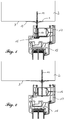
- Fig. 1 shows a cross section through a commercial window with frame 17 and sash 18 each made of PVC-u and a steel reinforcement 16 after mounting in accordance with the invention in the soffit 3.
- the distance of the frame 17 of the soffit 3 is circumferentially about 20 mm.
- the self-tapping screw 14 is not performed in this embodiment by the steel reinforcement 16 but by a separate from the steel reinforcement chamber so-called anchor chamber, wherein one of the WO 2014/135708 A1 known, so-called Dübelhuntadapter 15 the screw positioned in the Blendrahmenfalz and seals against this.
- Fig. 2 an alternative embodiment of the invention is shown: in this embodiment, the screw 14 is screwed through the steel reinforcement 16, the other steps are analogous to the first embodiment.
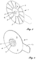
- the fixing device 1 according to the invention is shown in a perspective view of the bottom 6 and the top 5.
- the fixing device 1 is made by injection molding of PVC-u.
- the soffit 3 facing bottom 6 a plurality of ribs 7 and a plurality of teeth 8, which can dig into the unevenness of the surface of the soffit 3 with appropriate masonry, such as a brick masonry, so as otherwise exclusively frictional power transmission from the fixing device 1 to support the soffit 3 by appropriate positive engagement.
- appropriate masonry such as a brick masonry
- the tab 13 which facilitates the holding of the fixing device 1 in the space between the frame back and the soffit 3 when screwing the screw 14 into the fixing device 1. Once the screw 14 has been screwed into the fixing device 1, this tab 13 has no further function.
- the hexagon 9 is integrally formed with the centering funnel 10 and the opening 11.
- the centering funnel 10 serves for easier insertion of the screw 14, while the hexagon 9 serves for the final rotation of the base body 4 relative to the reveal 3 and thus for pressing against the reveal 3.
- Fig. 5 to 7 is the fixing device according to the invention again in the views from below ( Fig. 5 ), above ( Fig. 7 ) as well as on average in Fig. 6 shown.
- the main body 4 has a substantially flat, but slightly curved to the top 5 shape, centrally on the base 4 on the top of the hexagon 9 and on the bottom of the guide cone 12 are formed.
Landscapes
- Engineering & Computer Science (AREA)
- Mechanical Engineering (AREA)
- Civil Engineering (AREA)
- Structural Engineering (AREA)
- Bolts, Nuts, And Washers (AREA)
- Connection Of Plates (AREA)
- Joining Of Building Structures In Genera (AREA)
Priority Applications (3)
| Application Number | Priority Date | Filing Date | Title |
|---|---|---|---|
| EP16154973.8A EP3205805A1 (fr) | 2016-02-10 | 2016-02-10 | Procede et dispositif de fixation d'un dormant sur une surface interieure |
| EP17155673.1A EP3205806B1 (fr) | 2016-02-10 | 2017-02-10 | Procede et dispositif de fixation d'un dormant sur une surface interieure |
| DE102017102718.1A DE102017102718A1 (de) | 2016-02-10 | 2017-02-10 | Verfahren und Vorrichtung zur Befestigung eines Blendrahmens an einer Laibung |
Applications Claiming Priority (1)
| Application Number | Priority Date | Filing Date | Title |
|---|---|---|---|
| EP16154973.8A EP3205805A1 (fr) | 2016-02-10 | 2016-02-10 | Procede et dispositif de fixation d'un dormant sur une surface interieure |
Publications (1)
| Publication Number | Publication Date |
|---|---|
| EP3205805A1 true EP3205805A1 (fr) | 2017-08-16 |
Family
ID=55353053
Family Applications (2)
| Application Number | Title | Priority Date | Filing Date |
|---|---|---|---|
| EP16154973.8A Withdrawn EP3205805A1 (fr) | 2016-02-10 | 2016-02-10 | Procede et dispositif de fixation d'un dormant sur une surface interieure |
| EP17155673.1A Active EP3205806B1 (fr) | 2016-02-10 | 2017-02-10 | Procede et dispositif de fixation d'un dormant sur une surface interieure |
Family Applications After (1)
| Application Number | Title | Priority Date | Filing Date |
|---|---|---|---|
| EP17155673.1A Active EP3205806B1 (fr) | 2016-02-10 | 2017-02-10 | Procede et dispositif de fixation d'un dormant sur une surface interieure |
Country Status (2)
| Country | Link |
|---|---|
| EP (2) | EP3205805A1 (fr) |
| DE (1) | DE102017102718A1 (fr) |
Citations (4)
| Publication number | Priority date | Publication date | Assignee | Title |
|---|---|---|---|---|
| DE1972595U (de) | 1967-07-04 | 1967-11-16 | Hubert Ebel | Wattestueck. |
| DE102008012025A1 (de) | 2008-02-29 | 2009-09-03 | Müller & Jehle GmbH | Rahmen zur Montage in einer Wandöffnung und Montagevorrichtung für einen Rahmen |
| EP2775083A2 (fr) * | 2013-03-08 | 2014-09-10 | SFS intec Holding AG | Dispositif et procédé de fixation d'un corps de bâtiment dans une ouverture limitée par une surface d'appui |
| WO2014135708A1 (fr) | 2013-03-08 | 2014-09-12 | Profine Gmbh | Procédé pour la fixation d'un dormant à une maçonnerie, à l'aide d'un adaptateur à chambre à goujon |
-
2016
- 2016-02-10 EP EP16154973.8A patent/EP3205805A1/fr not_active Withdrawn
-
2017
- 2017-02-10 DE DE102017102718.1A patent/DE102017102718A1/de not_active Withdrawn
- 2017-02-10 EP EP17155673.1A patent/EP3205806B1/fr active Active
Patent Citations (4)
| Publication number | Priority date | Publication date | Assignee | Title |
|---|---|---|---|---|
| DE1972595U (de) | 1967-07-04 | 1967-11-16 | Hubert Ebel | Wattestueck. |
| DE102008012025A1 (de) | 2008-02-29 | 2009-09-03 | Müller & Jehle GmbH | Rahmen zur Montage in einer Wandöffnung und Montagevorrichtung für einen Rahmen |
| EP2775083A2 (fr) * | 2013-03-08 | 2014-09-10 | SFS intec Holding AG | Dispositif et procédé de fixation d'un corps de bâtiment dans une ouverture limitée par une surface d'appui |
| WO2014135708A1 (fr) | 2013-03-08 | 2014-09-12 | Profine Gmbh | Procédé pour la fixation d'un dormant à une maçonnerie, à l'aide d'un adaptateur à chambre à goujon |
Also Published As
| Publication number | Publication date |
|---|---|
| DE102017102718A1 (de) | 2017-08-10 |
| EP3205806A1 (fr) | 2017-08-16 |
| EP3205806B1 (fr) | 2022-04-06 |
Similar Documents
| Publication | Publication Date | Title |
|---|---|---|
| EP0292742B1 (fr) | Vis d'écartement | |
| EP1857607A2 (fr) | Elément et méthode de fixation de panneaux isolants | |
| EP1533185A1 (fr) | Elément de compensation de déviations de tolérance | |
| DE1801913A1 (de) | Anordnung von Beschlagteilen in Profilrahmen von Fenstern,Tueren od.dgl. | |
| DE19642914C2 (de) | Dübel | |
| DE102008010606A1 (de) | Befestigungselement für Holzfaserdämmplatten | |
| EP3540160B1 (fr) | Agencement de fixation permettant de fixer une penture sur un profilé creux | |
| EP0872619A2 (fr) | Elément d'ajustement | |
| EP2525107A2 (fr) | Dispositif d'ancrage d'échafaudage | |
| EP1046764A1 (fr) | Dispositif pour la fixation à distance de plaques d'isolation aux murs ou aux plafonds | |
| WO2015165661A1 (fr) | Raccord de profilés et assemblage de profilés | |
| EP1651873A1 (fr) | Dispositif comportant deux profiles creux assembles par une vis et outil correspondant | |
| EP3567264B1 (fr) | Système de fixation | |
| EP2844884B1 (fr) | Vis pour matériaux de construction légers | |
| DE102011111064A1 (de) | Anordnung zur, insbesondere distanzierten, Befestigung zumindest einer Dammstoffplatte an einem Gebäude | |
| EP3205806B1 (fr) | Procede et dispositif de fixation d'un dormant sur une surface interieure | |
| EP3037682B1 (fr) | Élement de fixation destine a fixer des composants de construction sur des parois de batiment isolees | |
| DE3611873A1 (de) | Befestigungselement zum verstellbaren befestigen von bauelementen an bauwerken | |
| DE102010020278B4 (de) | Vorrichtung zur Bereitstellung eines Befestigungspunktes an einem Profilelement | |
| AT402335B (de) | Justierdübelsystem zur einstellbaren verbindung zweier elemente miteinander sowie eine gewindehülse, eine verankerungshülse, ein verankerungselement und eine bohrhilfe für das justierdübelsystem | |
| EP3962325B1 (fr) | Crochet mural, dispositif de fixation avec le crochet mural et procédé de fixation du crochet mural | |
| EP3450647A1 (fr) | Dispositif de fixation pour matériau d'isolation | |
| EP0196485A1 (fr) | Dispositif de fixation d'un élément de construction sur un mur ou une autre partie de bâtiment | |
| EP0286706A1 (fr) | Cheville | |
| EP3322904B1 (fr) | Procédé pour réaliser une liaison |
Legal Events
| Date | Code | Title | Description |
|---|---|---|---|
| PUAI | Public reference made under article 153(3) epc to a published international application that has entered the european phase |
Free format text: ORIGINAL CODE: 0009012 |
|
| AK | Designated contracting states |
Kind code of ref document: A1 Designated state(s): AL AT BE BG CH CY CZ DE DK EE ES FI FR GB GR HR HU IE IS IT LI LT LU LV MC MK MT NL NO PL PT RO RS SE SI SK SM TR |
|
| AX | Request for extension of the european patent |
Extension state: BA ME |
|
| STAA | Information on the status of an ep patent application or granted ep patent |
Free format text: STATUS: THE APPLICATION IS DEEMED TO BE WITHDRAWN |
|
| 18D | Application deemed to be withdrawn |
Effective date: 20180217 |