EP3205811A1 - Ablageschale für eine leiter und leiter mit dieser ablageschale - Google Patents
Ablageschale für eine leiter und leiter mit dieser ablageschale Download PDFInfo
- Publication number
- EP3205811A1 EP3205811A1 EP17155209.4A EP17155209A EP3205811A1 EP 3205811 A1 EP3205811 A1 EP 3205811A1 EP 17155209 A EP17155209 A EP 17155209A EP 3205811 A1 EP3205811 A1 EP 3205811A1
- Authority
- EP
- European Patent Office
- Prior art keywords
- tray
- plug
- receptacle
- buckle
- hook
- Prior art date
- Legal status (The legal status is an assumption and is not a legal conclusion. Google has not performed a legal analysis and makes no representation as to the accuracy of the status listed.)
- Granted
Links
Images


Classifications
-
- E—FIXED CONSTRUCTIONS
- E06—DOORS, WINDOWS, SHUTTERS, OR ROLLER BLINDS IN GENERAL; LADDERS
- E06C—LADDERS
- E06C7/00—Component parts, supporting parts, or accessories
- E06C7/14—Holders for pails or other equipment on or for ladders
-
- B—PERFORMING OPERATIONS; TRANSPORTING
- B25—HAND TOOLS; PORTABLE POWER-DRIVEN TOOLS; MANIPULATORS
- B25H—WORKSHOP EQUIPMENT, e.g. FOR MARKING-OUT WORK; STORAGE MEANS FOR WORKSHOPS
- B25H3/00—Storage means or arrangements for workshops facilitating access to, or handling of, work tools or instruments
- B25H3/06—Trays
-
- E—FIXED CONSTRUCTIONS
- E06—DOORS, WINDOWS, SHUTTERS, OR ROLLER BLINDS IN GENERAL; LADDERS
- E06C—LADDERS
- E06C7/00—Component parts, supporting parts, or accessories
- E06C7/18—Devices for preventing persons from falling
- E06C7/181—Additional gripping devices, e.g. handrails
- E06C7/182—Additional gripping devices, e.g. handrails situated at the top of the ladder
-
- E—FIXED CONSTRUCTIONS
- E06—DOORS, WINDOWS, SHUTTERS, OR ROLLER BLINDS IN GENERAL; LADDERS
- E06C—LADDERS
- E06C1/00—Ladders in general
- E06C1/02—Ladders in general with rigid longitudinal member or members
- E06C1/38—Special constructions of ladders, e.g. ladders with more or less than two longitudinal members, ladders with movable rungs or other treads, longitudinally-foldable ladders
- E06C1/39—Ladders having platforms; Ladders changeable into platforms
-
- E—FIXED CONSTRUCTIONS
- E06—DOORS, WINDOWS, SHUTTERS, OR ROLLER BLINDS IN GENERAL; LADDERS
- E06C—LADDERS
- E06C7/00—Component parts, supporting parts, or accessories
- E06C7/18—Devices for preventing persons from falling
- E06C7/186—Rail or rope for guiding a safety attachment, e.g. a fall arrest system
Definitions
- the present invention relates to a tray. Furthermore, the invention relates to a ladder with this tray.
- U1 is a step ladder with a tray known.
- the tray connects upper ends of bars of a riser of step ladder.
- the tray has various holes that can serve as receptacles for inserting tools such as screwdrivers or for inserting power tools such as electric screwdrivers or drills.
- a compartment is provided in which all kinds of items such as screws or other small parts can be stored.
- a so-called bucket hook is provided on which a bucket or other items can be attached or attached.
- the present invention is based on the object to propose a tray that allows greater flexibility and better protection of the attached items.
- the tray has a first receptacle for a part of a plug-in buckle, which can be attached to the tray.
- the tray has a plurality of second receptacles for hooks that can be attached to the tray.
- a plug-in buckle is a closure assembly such as that in the document DE 203 16 449 U1 is described. Usually plug-in closures are used to close belt connections. Plug closure are used in particular on bags to close the lid of a bag.
- the first receptacle of a storage tray according to the invention may be a through hole. At least one stop for the first part of the plug-in buckle can be arranged in this through-hole. With the help of the stopper, a simple positioning of the first part of the plug-in buckle is possible.
- the first part may be a male plug-in closure part.
- the first part of the plug-in buckle can be inserted from a first side of the tray into the first receptacle.
- the first receptacle is further configured such that a second part of the plug-in buckle can be inserted from a second side of the storage tray into the first receptacle.
- This second part of the plug-in buckle may be a female plug-in closure part.
- the tray has transversely to the first receptacle at least a first hole through which a securing means for securing the first part of the plug-in buckle is inserted into the first receptacle.
- the second receptacles of a storage tray according to the invention may have, at least in sections, a non-circular first cross-sectional area.
- This non-circular cross-sectional area makes it necessary that a hook can be inserted into the second receptacle only in a certain position and removed from the second receptacle, whereby a random falling out of the hooks from the second receptacles is made more difficult.
- At least one of the second receptacles may have a take-up direction that is aligned parallel to an upper surface of the storage tray. Likewise, at least one of the second receptacles have a receiving direction, which is aligned perpendicular to the top of the tray. This makes it possible to attach hooks in different positions on the tray.
- a first part of the plug-in buckle may be attached to a first end of the belt and the first part of the plug-in buckle may be inserted from the first side of the tray in the first receptacle of the tray.
- the first part of the plug-in buckle can be fastened to the abutment.
- the arrangement may comprise a securing means, for example a pin or a bow or a split pin, which passes through the at least one first hole in the tray into a recess is inserted in the first part of the plug-in buckle, to secure the first part of the plug-in buckle against being pulled out of the first receptacle.
- a securing means for example a pin or a bow or a split pin, which passes through the at least one first hole in the tray into a recess is inserted in the first part of the plug-in buckle, to secure the first part of the plug-in buckle against being pulled out of the first receptacle.
- a second part of the plug-in buckle is attached to a second end of the belt.
- the first and second ends of the belt may be connected together to form a loop.
- this loop objects can be hung or secured to the tray or a hook on the tray suspended objects are secured.
- the hook may have a plug-in portion which is inserted in one of the second receptacles.
- the male portion of the hook may have a cross-sectional area at at least one location or in an area corresponding to the first cross-sectional area of the second seats.
- the insertion portion of the hook and the second recordings act like a key and a lock together, so that the hook can be used in only one or a few positions in the second recordings and removed again from the second recordings.
- the hook of an arrangement according to the invention can be angled approximately 90 ° to the insertion portion having an intermediate portion and angled approximately 90 ° to the intermediate portion having a hook portion, wherein the intermediate portion connects the male portion and the hook portion.
- This double bend has the advantage that the hook portion are pivoted in a large angular range can take to different positions relative to the tray.
- the tray A shown in the figures has many elements, as they already from the tray of step ladder from the document DE 20 2007 002 103 U1 are known.
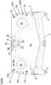
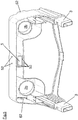
- the tray has u.a. two sockets 3, with which the tray can be inserted into upper ends of bars of a riser of a step ladder and attached to these upper ends of the spars.
- the two sockets 3 are connected by a central region 1, in which a compartment 2a is provided for the storage of objects.
- two circular through holes 2b are provided which can serve as receptacles for hand tool machines, for example for a cordless screwdriver.
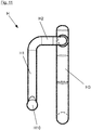
- the tray on two known through holes 4, which can accommodate rods 7 of a bracket 7, 8, which is slidably guided in the bars of step ladder, which in itself from the document DE 20 2007 002 103 U1 is known.
- the document is DE 20 2007 002 103 U1 directed.
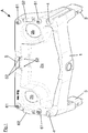
- the storage tray has a first receptacle 5. This is formed by a through hole extending from an upper side to a Bottom of the tray A extends and has a substantially rectangular cross-section.
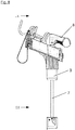
- a plug-in buckle S in the first receptacle 5 is arranged.
- a first part S1 of the plug-in buckle S is fastened in the receptacle 5.
- first part S1 of the plug-in buckle S is the male part of the plug-in buckle S
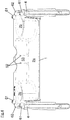
- a securing is possible in that two outwardly curved tines S10 of the first plug-in closing part S1 are pressed inwards when inserting the male plug-in closing part S1 Stop 50 to be moved past, which is arranged in the first receptacle 5.
- a shoulder S11 of the first plug-in closure part S1 can come into abutment against the stop 50.
- the first plug-in closure part S1 of the illustrated embodiment is inserted from below into the first recess 5.
- two smaller through holes 52 are provided at a distance from each other, which extend through the first receptacle 5 bounding walls 53 of the tray A.
- the through-holes 52 also extend through a wall 53 delimiting the compartment 2 and a wall 53 on the back of the storage tray.
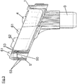
- the first part S1 of the plug-in buckle S inserted in the first receptacle 5 has through-holes or a continuous slot S12. Legs of a U-shaped bracket K can be inserted through these holes or the slot S12 in the first part S1 of the plug-in buckle S and the through-holes 52 in the region of the first receptacle 5 in order to secure the first part S1 of the plug-in buckle S in the receptacle 5 ,
- a first end of a belt G is attached.
- a second plug-in closure part S2 is attached, in the present example, the female plug closure part.
- This second plug-in closure part S2 has a receptacle into which the prongs S10 of the first plug-in closure part S1 can be inserted and latched in a manner known per se.
- the second part S2 of the plug-in buckle S can be inserted from above into the first receptacle 5 of the storage tray A and plugged onto the prongs S10 of the first part S1 of the plug-in buckle S.
- the belt G then forms a loop with which objects can be hung and secured.
- the tray A also has second receptacles 61, 62 for hooks H, which can be attached to the tray A.
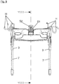
- the second receptacles 61, 62 there are four second receptacles 61, which have a receiving direction for the hooks H perpendicular to the top of the tray A.
- Two further second receptacles 62 have a receiving direction, which runs parallel to the top of the tray A. This makes it possible to attach hooks H differently oriented on the tray A.
- the two second second receptacles 62 are aligned so that a tool handle, for example the broomstick of a broom, can be hung by means of the hook H. as known in the art.
- the second receptacles 61, 62 have at least in a region 610, 620 a first cross-sectional area, which is not circular (see in particular Fig. 2a , second pictures 61, 62).
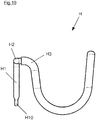
- This first cross-sectional area is chosen so that it is adapted to a region H10 with a first cross-sectional area of a plug-in portion H1 of the hooks H.
- the insertion portion H1 has this first cross-sectional area in the region H10, which is first inserted into the second receptacles 61, 62 when one of the hooks H in the second receptacle 61, 62 attached.
- This end portion H1 having the first cross-sectional area cooperates with the portion 610, 620 of the second receptacles 61, 62 having the first cross-sectional area similar to a key and a keyhole.
- An insertion is possible only in certain positions.
- a release of the hook ie a withdrawal of the insertion of the hook only in certain positions possible.
- a random falling out is not completely prevented, but at least severely limited.
- the first cross-sectional area in the end portion H10 of the Einsteckabitess H1 additionally has a slight excess, and the Einstecksteck Scheme H1 can be used only with a slight elastic deformation in the second receptacles 61, 62. Also by the hook H is secured against accidental falling out.
- the second second receptacles 62 can have a region 620 with a first cross-sectional area both in an initial region and in an end region (viewed in the insertion direction of the insertion sections of the hook H).
- the hooks H have in addition to the insertion portion H1 to an angled about 90 ° intermediate portion H2. This is in turn followed by 90 ° angled hook section H3, which is used for hanging or attaching the objects that at the Tray A should be attached.
- This hook portion H3 is bent substantially U-shaped and provided with a slip-resistant plastic coating.
Landscapes
- Engineering & Computer Science (AREA)
- Mechanical Engineering (AREA)
- Vehicle Step Arrangements And Article Storage (AREA)
- Purses, Travelling Bags, Baskets, Or Suitcases (AREA)
- Ladders (AREA)
- Valve-Gear Or Valve Arrangements (AREA)
- Package Frames And Binding Bands (AREA)
Abstract
Description
- Die vorliegende Erfindung betrifft eine Ablageschale. Ferner betrifft die Erfindung eine Leiter mit dieser Ablageschale.
- Aus dem Dokument
DE 20 2007 002 103 U1 ist eine Stufenstehleiter mit einer Ablageschale bekannt. Die Ablageschale verbindet obere Enden von Holmen eines Steigteils der Stufenstehleiter. Die Ablageschale weist verschiedene Löcher auf, die als Aufnahmen zum Einstecken von Werkzeugen wie Schraubendrehern oder zum Einstecken von Handwerkzeugmaschinen wie Akkuschrauber oder Bohrmaschinen dienen können. Außerdem ist ein Fach vorgesehen, in welchem allerlei Gegenstände wie Schrauben oder andere Kleinteile abgelegt werden können. Schließlich ist auch ein sogenannter Eimerhaken vorgesehen, an welchem ein Eimer oder auch andere Gegenstände ein- oder angehängt werden können. - Es hat sich in der Vergangenheit gezeigt, dass die aus dem Dokument
DE 20 2007 002 103 U1 bekannte Ablageschale ihren Zweck erfüllt. Gelegentlich wurde aber der Wunsch geäußert, den an dem Eimerhaken angehängten Gegenstand besser zu sichern. Außerdem wurde der Wunsch geäußert, dass man mehrere Gegenstände gleichzeitig an der Ablageschale ein- oder anhängen kann. Außerdem wurde eine größere Flexibilität dahingehend gewünscht, dass an verschiedenen Seiten der Ablageschale Gegenstände ein- oder angehängt werden können. - Hier setzt die vorliegende Erfindung an.
- Der vorliegenden Erfindung liegt die Aufgabe zu Grunde, eine Ablageschale vorzuschlagen, die eine größere Flexibilität und eine bessere Sicherung der angehängten Gegenstände ermöglicht.
- Diese Aufgabe wird erfindungsgemäß dadurch gelöst, dass die Ablageschale eine erste Aufnahme für ein Teil einer Steckschließe aufweist, die an der Ablageschale befestigt werden kann.
- Diese Aufgabe wird ferner dadurch gelöst, dass die Ablageschale mehrere zweite Aufnahmen für Haken aufweist, die an der Ablageschale befestigt werden können.
- Eine Steckschließe ist eine Verschlussanordnung wie sie zum Beispiel in dem Dokument
DE 203 16 449 U1 beschrieben ist. Üblicherweise werden Steckschließen verwendet, um Gurtverbindungen zu schließen. Steckschließen werden insbesondere an Taschen verwendet, um den Deckel einer Tasche zu verschließen. - Die erste Aufnahme einer erfindungsgemäßen Ablageschale kann ein Durchgangsloch sein. In diesem Durchgangsloch kann wenigstens ein Anschlag für das erste Teil der Steckschließe angeordnet sein. Mit Hilfe des Anschlags ist ein einfaches Positionieren des ersten Teils der Steckschließe möglich. Bei dem ersten Teil kann es sich um ein männliches Steckschließenteil handeln.
- Gemäß der Erfindung kann vorgesehen sein, dass das erste Teil der Steckschließe von einer ersten Seite der Ablageschale in die erste Aufnahme eingeführt werden kann.
- Die erste Aufnahme ist ferner so gestaltet, dass ein zweites Teil der Steckschließe von einer zweiten Seite der Ablageschale in die erste Aufnahme einführbar ist. Dieses zweite Teil der Steckschließe kann ein weibliches Steckschließenteil sein.
- Erfindungsgemäß kann vorgesehen sein, dass die Ablageschale quer zur ersten Aufnahme wenigstens ein erstes Loch hat, durch welches ein Sicherungsmittel zur Sicherung des ersten Teils der Steckschließe in die erste Aufnahme einführbar ist.
- Die zweiten Aufnahmen einer erfindungsgemäßen Ablageschale können zumindest abschnittweise eine nicht kreisförmige erste Querschnittsfläche aufweisen. Diese nicht kreisförmige Querschnittsfläche macht es erforderlich, dass ein Haken nur in einer bestimmten Stellung in die zweite Aufnahme eingesetzt und aus der zweiten Aufnahme entnommen werden kann, wodurch auch ein zufälliges Herausfallen der Haken aus den zweiten Aufnahmen erschwert wird.
- Wenigstens eine der zweiten Aufnahmen kann eine Aufnahmerichtung haben, die parallel zu einer Oberseite der Ablageschale ausgerichtet ist. Ebenso kann wenigstens eine der zweiten Aufnahmen eine Aufnahmerichtung haben, die senkrecht zur Oberseite der Ablageschale ausgerichtet ist. Damit ist es möglich, Haken in unterschiedlichen Lagen an der Ablageschale zu befestigen.
- Bei einer Anordnung aus einer erfindungsgemäßen Ablageschale, einem Gurt und einer Steckschließe, kann ein erstes Teil der Steckschließe an einem ersten Ende des Gurtes befestigt sein und das erste Teil der Steckschließe kann von der ersten Seite der Ablageschale in die erste Aufnahme der Ablageschale eingeführt sein. In der ersten Aufnahme kann das erste Teil der Steckschließe an dem Anschlag anliegend befindlich befestigt sein.
- Die Anordnung kann ein Sicherungsmittel, zum Beispiel einen Stift oder einen Bügel oder einen Splint aufweisen, das durch das wenigstens eine erste Loch in die Ablageschale in eine Ausnehmung in dem ersten Teil der Steckschließe eingeführt ist, um das erste Teil der Steckschließe gegen ein Herausziehen aus der ersten Aufnahme zu sichern.
- Vorzugsweise ist ein zweites Teil der Steckschließe an einem zweiten Ende des Gurtes befestigt. Durch das Verbinden des ersten und des zweiten Steckschließenteils können das erste und das zweite Ende des Gurtes miteinander verbunden sein und eine Schlaufe bilden. Mittels dieser Schlaufe können Gegenstände aufgehängt oder an der Ablageschale oder einem Haken an der Ablageschale aufgehängte Gegenstände gesichert werden.
- Bei einer erfindungsgemäßen Anordnung aus einer Ablageschale und einem Haken, kann der Haken einen Einsteckabschnitt aufweisen, der in einer der zweiten Aufnahmen eingesteckt ist.
- Der Einsteckabschnitt des Hakens kann an wenigstens einer Stelle oder in einem Bereich eine Querschnittsfläche haben, die der ersten Querschnittsfläche der zweiten Aufnahmen entspricht. Der Einsteckabschnitt des Hakens und die zweiten Aufnahmen wirken wie ein Schlüssel und ein Schloss zusammen, so dass der Haken in möglichst nur einer oder wenigen Stellungen in die zweiten Aufnahmen eingesetzt und wieder aus den zweiten Aufnahmen herausgenommen werden kann.
- Der Haken einer erfindungsgemäßen Anordnung kann um ca. 90° abgewinkelt zu dem Einsteckabschnitt einen Zwischenabschnitt aufweisen und um ca. 90° abgewinkelt zu dem Zwischenabschnitt einen Hakenabschnitt aufweisen, wobei der Zwischenabschnitt den Einsteckabschnitt und den Hakenabschnitt miteinander verbindet. Diese zweifache Abwinkelung hat den Vorteil, dass der Hakenabschnitt in einem großen Winkelbereich geschwenkt werden kann, um verschiedene Stellungen relativ zu der Ablageschale einzunehmen.
- Weitere Merkmale und Vorteile der vorliegenden Erfindung werden deutlich anhand der nachfolgenden Beschreibung eines bevorzugten Ausführungsbeispiels unter Bezugnahme auf die beiliegenden Abbildungen. Darin zeigen:
- Fig. 1
- eine Ansicht der Ablageschale aus der Vogelperspektive,
- Fig. 2
- eine Draufsicht auf die Ablageschale,
- Fig. 2a
- eine gegenüber der Draufsicht nach
Fig. 2 leicht gedrehte Ansicht auf die Ablageschale von oben, - Fig. 3
- eine Ansicht der Ablageschale auf eine Schnittfläche III-III in
Fig. 2 , - Fig. 4
- eine Ansicht der Ablageschale auf eine Schnittfläche IV-IV in
Fig. 2 , - Fig. 5
- eine Ansicht der Ablageschale aus der Froschperspektive,
- Fig. 6
- eine Ansicht der Ablageschale von der Rückseite (siehe Pfeil VI in
Fig. 4 ) - Fig. 7
- eine Ansicht einer Anordnung aus der erfindungsgemäßen Ablageschale gemäß den
Figuren 1 bis 6 , einem Bügel, einem Gurt, einer Steckschließe und Haken, - Fig. 8
- eine Schnittansicht der Anordnung und
- Fig. 8a
- einen Ausschnitt aus der Schnittansicht der
Fig. 8 , - Fig. 9
- eine Ansicht der Anordnung auf eine Schnittfläche IX-IX in
Fig. 8 ., - Fig. 9a
- einen Ausschnitt aus der Schnittansicht der
Fig. 9 , - Fig. 10
- eine erste Ansicht eines Hakens,
- Fig. 11
- eine zweite Ansicht des Hakens und
- Fig. 12
- eine Ansicht einer Klammer.
- Die in den Figuren dargestellte Ablageschale A weist viele Elemente auf, wie sie schon von der Ablageschale der Stufenstehleiter aus dem Dokument
DE 20 2007 002 103 U1 bekannt sind. - Die Ablageschale weist u.a. zwei Stutzen 3 auf, mit denen die Ablageschale in obere Enden von Holmen eines Steigteils einer Stufenstehleiter eingesteckt und an diesen oberen Enden der Holme befestigt werden kann. Die beiden Stutzen 3 werden von einem mittleren Bereich 1 verbunden, in dem ein Fach 2a für die Ablage von Gegenständen vorgesehen ist. Außerdem sind zwei kreisförmige Durchgangslöcher 2b vorgesehen, die als Aufnahmen für Handwerkzeugmaschinen, zum Beispiel für einen Akkuschrauber dienen können.
- Ferner weist die Ablageschale zwei an sich bekannte Durchgangslöcher 4 auf, die Stangen 7 eines Bügels 7, 8 aufnehmen können, der verschiebbar in den Holmen der Stufenstehleiter geführt ist, was an sich bereits aus dem Dokument
DE 20 2007 002 103 U1 bekannt ist. Insofern wird auf das DokumentDE 20 2007 002 103 U1 verwiesen. - Die Ablageschale weist eine erste Aufnahme 5 auf. Diese wird von einem Durchgangsloch gebildet, das sich von einer Oberseite zu einer Unterseite der Ablageschale A erstreckt und einen im Wesentlichen rechteckigen Querschnitt hat. In den
Fig. 7 bis 9a ist dargestellt, dass eine Steckschließe S in der ersten Aufnahme 5 angeordnet ist. Ein erstes Teil S1 der Steckschließe S ist dabei in der Aufnahme 5 befestigt. - Handelt es sich bei dem ersten Teil S1 der Steckschließe S um das männliche Teil der Steckschließe S, ist eine Sicherung dadurch möglich, dass beim Einsetzen des männlichen Steckschließenteils S1 zwei nach außen gewölbten Zinken S10 des ersten Steckschließenteils S1 nach innen gedrückt werden, um an einem Anschlag 50 vorbei bewegt zu werden, der in der ersten Aufnahme 5 angeordnet ist. Sobald die nach außen gewölbten Bereiche der Zinken S10 die Anschläge 50 passiert haben, kann ein Absatz S11 des ersten Steckschließenteils S1 an dem Anschlag 50 zu Anlage kommen. Das erste Steckschließenteil S1 des dargestellten Ausführungsbeispiels wird von unten in die erste Ausnehmung 5 eingeführt.
- Quer zu der ersten Aufnahme 5 sind in einem Abstand zu einander zwei kleinere Durchgangslöcher 52 vorgesehen, die sich durch die die erste Aufnahme 5 begrenzenden Wandungen 53 der Ablageschale A erstrecken. Die Durchgangslöcher 52 erstrecken sich auch durch eine das Fach 2 begrenzende Wand 53 und eine Wand 53 auf der Rückseite der Ablageschale.
- Das in der ersten Aufnahme 5 eingesetzte erste Teil S1 der Steckschließe S weist Durchgangslöcher oder einen durchgehenden Schlitz S12 auf. Durch diese Löcher bzw. den Schlitz S12 im ersten Teil S1 der Steckschließe S und die Durchgangslöcher 52 im Bereich der ersten Aufnahme 5 können Schenkel einer u-förmigen Klammer K eingesteckt werden, um das erste Teil S1 der Steckschließe S in der Aufnahme 5 zu sichern.
- Auf der den Zinken S10 abgewandten Seite des ersten Teils S1 der Steckschließe S ist ein erstes Ende eines Gurtes G befestigt. An einem zweiten Ende des Gurtes G ist ein zweites Steckschließenteil S2 befestigt, im vorliegenden Beispiel das weibliche Steckschließenteil. Dieses zweite Steckschließenteil S2 hat eine Aufnahme, in welche die Zinken S10 des ersten Steckschließenteils S1 eingeführt und auf an sich bekannte Art einrasten können. Dazu kann das zweite Teil S2 der Steckschließe S von oben in die erste Aufnahme 5 der Ablageschale A eingeführt und auf die Zinken S10 des ersten Teils S1 der Steckschließe S aufgesteckt werden. Der Gurt G bildet dann eine Schlaufe, mit der Gegenstände aufgehängt und gesichert werden können.
- Die Ablageschale A weist außerdem zweite Aufnahmen 61, 62 für Haken H auf, die an der Ablageschale A befestigt werden können. Unter den zweiten Aufnahmen 61, 62 gibt es vier zweite Aufnahmen 61, die eine zur Oberseite der Ablageschale A senkrechte Aufnahmerichtung für die Haken H haben. Zwei weitere zweite Aufnahmen 62 haben eine Aufnahmerichtung, die parallel zu der Oberseite der Ablageschale A verläuft. Dadurch ist es möglich, Haken H unterschiedlich ausgerichtet an der Ablageschale A zu befestigen.
- Während die in den vier ersten zweiten Aufnahmen 61 eingesteckten Haken H so ausgerichtet sind, das man Gegenstände einhängen kann, sind die zwei zweiten zweiten Aufnahmen 62 so ausgerichtet, dass man einen Gerätestiel, zum Beispiel den Besenstiel eines Besens, mittels des Hakens H aufhängen kann, wie es aus dem Stand der Technik bekannt ist.
- Die zweiten Aufnahmen 61, 62 weisen zumindest in einem Bereich 610, 620 eine erste Querschnittsfläche auf, die nicht kreisförmig ist (siehe insbesondere
Fig. 2a , zweite Aufnahmen 61, 62). Diese erste Querschnittsfläche ist so gewählt, dass sie an einen Bereich H10 mit einer ersten Querschnittsfläche eines Einsteckabschnitts H1 der Haken H angepasst ist. Der Einsteckabschnitt H1 hat diese erste Querschnittsfläche in dem Bereich H10, der zuerst in die zweiten Aufnahmen 61, 62 gesteckt wird, wenn man einen der Haken H in der zweiten Aufnahme 61, 62 befestigt. Dieser Endbereich H1 mit der ersten Querschnittsfläche wirkt mit dem Bereich 610, 620 der zweiten Aufnahmen 61, 62 mit der ersten Querschnittsfläche ähnlich einem Schlüssel und einem Schlüsselloch zusammen. Ein Einsetzen ist nur in bestimmten Stellungen möglich. Ebenso ist ein Lösen des Hakens, d.h. ein Herausziehen des Einsteckabschnittes des Hakens nur in bestimmten Stellungen möglich. Dadurch ist ein zufälliges Herausfallen zwar nicht vollständig verhindert, aber zumindest stark eingeschränkt. - Vorzugsweise ist es möglich, dass die erste Querschnittsfläche im Endbereich H10 des Einsteckabschnitts H1 zusätzlich ein leichtes Übermaß hat, und der Einstecksteckbereich H1 nur bei einer leichten elastischen Verformung in die zweiten Aufnahmen 61, 62 eingesetzt werden kann. Auch dadurch ist der Haken H gegen ein zufälliges Herausfallen gesichert.
- Die zweiten zweiten Aufnahmen 62 können sowohl in einem Anfangsbereich als auch in einem Endbereich (in Einführrichtung der Einsteckabschnitte des Hakens H betrachtet) einen Bereich 620 mit einer ersten Querschnittsfläche aufweisen.
- Die Haken H haben neben dem Einsteckabschnitt H1 einen dazu um ca. 90° abgewinkelten Zwischenabschnitt H2. An diesen schließt sich wiederum um 90° abgewinkelt der Hakenabschnitt H3 an, der dem Einhängen oder Anhängen der Gegenstände dient, die an der Ablageschale A befestigt werden sollen. Dieser Hakenabschnitt H3 ist im Wesentlichen U-förmig gebogen und mit einem rutschhemmenden Kunststoffüberzug versehen.
Claims (15)
- Ablageschale (A) für eine Leiter, insbesondere für eine Stufenstehleiter, wobei die Ablageschale (A) wenigstens ein Fach (2b) aufweist, in dem Gegenstände ablegbar sind,
dadurch gekennzeichnet, dass
die Ablageschale (A) eine erste Aufnahme (5) für ein erstes Teil (S1) einer Steckschließe (S) aufweist, die an der Ablageschale (A) befestigbar ist. - Ablageschale (A) nach Anspruch 1, dadurch gekennzeichnet, dass die erste Aufnahme (5) ein Durchgangsloch ist, in dem wenigstens ein Anschlag (50) für das erste Teil (S1) der Steckschließe (S) angeordnet ist.
- Ablageschale (A) nach Anspruch 2, dadurch gekennzeichnet, dass das erste Teil (S1) der Steckschließe (S1) von einer ersten Seite der Ablageschale (A) in die ersten Aufnahme (5) einführbar ist.
- Ablageschale (A) nach Anspruch 3, dadurch gekennzeichnet, dass ein zweites Teil (S2) der Steckschließe (S) von einer zweiten Seite (S2) der Ablageschale (A) in die erste Aufnahme (5) einführbar ist.
- Ablageschale (A) nach Anspruch 2, 3 oder 4, dadurch gekennzeichnet, dass die Ablageschale (A) quer zur ersten Aufnahme (5) wenigstens ein erstes Loch (52) hat, durch welches ein Sicherungsmittel (K) zur Sicherung des ersten Teils (S1) der Steckschließe (S) in die erste Aufnahme (A) einführbar ist.
- Anordnung aus einer Ablageschale (A) nach einem der Ansprüche 1 bis 5, einem Gurt (G) und einer Steckschließe (S), dadurch gekennzeichnet, dass ein erstes Teil (S1) der Steckschließe (S) an einem ersten Ende des Gurtes (G) befestigt ist und das erste Teil (S1) der Steckschließe (S) von der ersten Seite der Ablageschale (A) in die erste Aufnahme (5) der Ablageschale (A) eingeführt ist und in der ersten Aufnahme (5) an dem Anschlag (50) in der ersten Aufnahme anliegend befindlich befestigt ist.
- Anordnung nach Anspruch 6, dadurch gekennzeichnet, dass die Anordnung ein Sicherungsmittel (K) aufweist, das durch das wenigstens eine erste Loch (52) in die Ablageschale (A) in eine Ausnehmung (S12) in dem ersten Teil (S1) der Steckschließe (S) eingeführt ist, um das erste Teil (S1) der Steckschließe (S) gegen ein Herausziehen aus der ersten Aufnahme (5) zu sichern.
- Anordnung nach Anspruch 6, dadurch gekennzeichnet, dass ein zweites Teil (S2) der Steckschließe (S) an einem zweiten Ende des Gurtes (G) befestigt ist.
- Ablageschale (A) mit den Merkmalen des Oberbegriffs des Anspruchs 1, insbesondere eines der Ansprüche 1 bis 8, dadurch gekennzeichnet, dass die Ablageschale (A) mehrere zweite Aufnahmen (61, 62) für Haken (H) aufweist, die an der Ablageschale (A) befestigbar sind.
- Ablageschale (A) nach Anspruch 9, dadurch gekennzeichnet, dass die zweiten Aufnahmen (61, 62) zumindest bereichsweise (610, 620) eine nicht kreisförmige erste Querschnittfläche hat.
- Ablageschale (A) nach Anspruch 10, dadurch gekennzeichnet, dass wenigstens eine zweite Aufnahme (62) eine Aufnahmerichtung hat, die parallel zu einer Oberseite der Ablageschale ausgerichtet ist.
- Ablageschale (A) nach Anspruch 10 oder 11, dadurch gekennzeichnet, dass wenigstens eine zweite Aufnahme (61) eine Aufnahmerichtung hat, die senkrecht zur Oberseite der Ablageschale (A) ausgerichtet ist.
- Anordnung aus einer Ablageschale (A) nach einem der Ansprüche 9 bis 12, und einem Haken (H), insbesondere Anordnung nach einem der Ansprüche 6 bis 8, dadurch gekennzeichnet, dass der Haken (H) einen Einsteckabschnitt (H1) aufweist, der in einer der zweiten Aufnahmen (61, 62) eingesteckt ist.
- Anordnung nach Anspruch 13, dadurch gekennzeichnet, dass der Einsteckabschnitt (H1) des Hakens (H) an wenigstens einer Stelle oder in einem Bereich (H10) eine Querschnittsfläche hat, die der ersten Querschnittsfläche in einem Bereich (610, 620) der zweiten Aufnahmen (610, 620) entspricht.
- Anordnung nach Anspruch 13 oder 14, dadurch gekennzeichnet, dass der Haken (H) um ca. 90° abgewinkelt zu dem Einsteckabschnitt (H1) ein Zwischenabschnitt (H2) aufweist und um ca. 90° abgewinkelt zu dem Zwischenabschnitt (H2) einen Hakenabschnitt (H3) aufweist, wobei der Zwischenabschnitt (H2) den Einsteckabschnitt (H1) und den Hakenabschnitt (H3) miteinander verbindet.
Applications Claiming Priority (1)
| Application Number | Priority Date | Filing Date | Title |
|---|---|---|---|
| DE202016100719.4U DE202016100719U1 (de) | 2016-02-12 | 2016-02-12 | Ablageschale für eine Leiter und Leiter mit dieser Ablageschale |
Publications (2)
| Publication Number | Publication Date |
|---|---|
| EP3205811A1 true EP3205811A1 (de) | 2017-08-16 |
| EP3205811B1 EP3205811B1 (de) | 2022-09-14 |
Family
ID=58009706
Family Applications (1)
| Application Number | Title | Priority Date | Filing Date |
|---|---|---|---|
| EP17155209.4A Active EP3205811B1 (de) | 2016-02-12 | 2017-02-08 | Ablageschale für eine leiter und leiter mit dieser ablageschale |
Country Status (7)
| Country | Link |
|---|---|
| US (1) | US10087682B2 (de) |
| EP (1) | EP3205811B1 (de) |
| DE (1) | DE202016100719U1 (de) |
| DK (1) | DK3205811T3 (de) |
| ES (1) | ES2931398T3 (de) |
| PL (1) | PL3205811T3 (de) |
| PT (1) | PT3205811T (de) |
Cited By (3)
| Publication number | Priority date | Publication date | Assignee | Title |
|---|---|---|---|---|
| CN108818484A (zh) * | 2018-01-22 | 2018-11-16 | 朱宰哲 | 摄像机模块制造用托盘 |
| EP3702575A1 (de) | 2019-02-28 | 2020-09-02 | CDH Group | Ablage-bord |
| USD984000S1 (en) | 2020-07-22 | 2023-04-18 | David Schoen | Ladder tray |
Families Citing this family (22)
| Publication number | Priority date | Publication date | Assignee | Title |
|---|---|---|---|---|
| US8376085B2 (en) * | 2006-02-03 | 2013-02-19 | Werner Co. | Electrician's ladder top |
| USD819834S1 (en) * | 2016-02-10 | 2018-06-05 | Hailo-Werk Rudolf Loh Gmbh & Co. Kg | Universal tray |
| US10612305B2 (en) * | 2016-12-30 | 2020-04-07 | Werner Co. | Ladder, Top and Method |
| US10590703B2 (en) * | 2016-12-30 | 2020-03-17 | Werner Co. | Ladder, top and method |
| CA3291256A1 (en) | 2018-06-08 | 2026-02-10 | Little Giant Ladder Systems, Llc | Combination ladders, ladder components and related methods |
| US11187039B2 (en) * | 2018-08-09 | 2021-11-30 | Louisville Ladder Inc. | Configurable ladder system and method |
| USD943772S1 (en) | 2018-10-19 | 2022-02-15 | Little Giant Ladder Systems, Llc | Flip-up ladder |
| USD935054S1 (en) | 2018-10-19 | 2021-11-02 | Little Giant Ladder Systems, Llc | Ladder |
| USD885607S1 (en) * | 2018-10-19 | 2020-05-26 | Wing Enterprises, Incorporated | Accessory for ladder |
| WO2020154675A1 (en) | 2019-01-25 | 2020-07-30 | Wing Enterprises, Incorporated | Foot for ladders, ladders incorporating same and related methods |
| USD912848S1 (en) | 2019-02-08 | 2021-03-09 | Little Giant Ladder Systems, Llc | Ladder accessory |
| USD911555S1 (en) | 2019-02-08 | 2021-02-23 | Little Giant Ladder Systems, Llc | Top cap for a ladder |
| CN114207243A (zh) * | 2019-06-04 | 2022-03-18 | 小巨人梯具系统有限公司 | 具有可调节托盘的活梯 |
| CN111595301B (zh) * | 2020-05-20 | 2021-11-23 | 福建省伟志地理信息科学研究院 | 一种地理信息系统用航空测量装置及其测量方法 |
| US12017339B1 (en) * | 2020-07-07 | 2024-06-25 | Kenneth Coburn Kotter | Tool organizer |
| US20220025705A1 (en) * | 2020-07-21 | 2022-01-27 | Jay Mislich | Ladder safety device |
| USD989985S1 (en) * | 2021-06-10 | 2023-06-20 | Joseph Nielo | Ladder mount tool holder |
| USD1088279S1 (en) | 2022-06-27 | 2025-08-12 | Werner Co. | Ladder top |
| USD1088277S1 (en) | 2022-06-27 | 2025-08-12 | Werner Co. | Ladder top |
| USD1065600S1 (en) | 2022-06-27 | 2025-03-04 | Werner Co. | Ladder top |
| USD1065599S1 (en) | 2022-06-27 | 2025-03-04 | Werner Co. | Ladder top |
| USD1041033S1 (en) * | 2023-09-26 | 2024-09-03 | Zhejiang Kangqian Industry & Trade Co., Ltd. | Sitting board for ladder |
Citations (7)
| Publication number | Priority date | Publication date | Assignee | Title |
|---|---|---|---|---|
| CH517891A (de) * | 1970-03-10 | 1972-01-15 | Loh Kg Hailo Werk | Sicherheitsbügel an Stehleitern |
| DE19803023C1 (de) * | 1998-01-27 | 1999-09-16 | Metall Kofler Kg | Anbauteil für Leitern sowie Rückfallsicherung und Werkzeughalterung zur Verwendung bei einem solchen Anbauteil |
| FR2812336A1 (fr) * | 2000-07-27 | 2002-02-01 | Frederic Tarabusi | Dispositif du type echelle a securite renforcee |
| US20020088668A1 (en) * | 2001-01-05 | 2002-07-11 | Moore Scott A. | Apparatus for securing ladder to building structure |
| DE20316449U1 (de) | 2003-10-25 | 2004-01-08 | Herzberg, Ralf, Dipl.-Ing. (FH) | Steckschliesse für Anbringung an eine bestehende Gurtschlaufe |
| EP1388640A1 (de) * | 2002-08-09 | 2004-02-11 | Innovations for Trade and Technology | Sicherheitsvorrichtung |
| DE202007002103U1 (de) | 2007-02-08 | 2007-04-19 | Hailo-Werk Rudolf Loh Gmbh & Co. Kg | Steiggerät mit einem höhenverstellbaren Bügel |
Family Cites Families (14)
| Publication number | Priority date | Publication date | Assignee | Title |
|---|---|---|---|---|
| US5639003A (en) * | 1995-02-16 | 1997-06-17 | Utzinger, Iii; Frederick J. | Convertible ladder caddy and tool belt |
| US5603405A (en) * | 1995-11-30 | 1997-02-18 | Smith; William H. | Ladder top storage rack |
| US5901998A (en) * | 1996-04-23 | 1999-05-11 | Gallo, Jr.; Joseph A. | Multi-functional tool and parts carrier |
| US5950972A (en) * | 1996-12-26 | 1999-09-14 | C.D.I. Enterprises, Inc. | Ladder mounted container |
| US6098748A (en) * | 1998-10-30 | 2000-08-08 | Harper, Jr.; Robert W. | Adjustable height tool bin system |
| US6158551A (en) * | 1999-02-25 | 2000-12-12 | Gray; Earl | Extension ladder shelf |
| US6604721B2 (en) * | 2000-03-28 | 2003-08-12 | Ahl, Inc. | Bracket assembly for attaching a container to a ladder |
| US6382354B2 (en) * | 2000-03-28 | 2002-05-07 | Ahl, Inc. | Ladder supported container |
| US6401862B1 (en) * | 2000-07-14 | 2002-06-11 | Jean Caron | Stepladder organizing assembly |
| US20020017430A1 (en) * | 2000-08-11 | 2002-02-14 | Rosko Michael Scot | Utility tray |
| US20020070137A1 (en) * | 2000-12-11 | 2002-06-13 | Kelley Hedges | Free-standing very-large-capacity flexible modular tool and material holder selectively mountable atop a step ladder |
| US6564941B2 (en) * | 2000-12-11 | 2003-05-20 | Ladder Boss, Inc. | Flexible truncated-pyramidally-shaped tool and material holder with a distended paint pail pouch for removable use atop a step ladder |
| US7753170B1 (en) * | 2006-10-09 | 2010-07-13 | Louisville Ladder Inc. | Ladder top for retaining a ladder against extrinsic surfaces |
| US20130319884A1 (en) * | 2012-06-05 | 2013-12-05 | Mark Gomez | Accessories for seating devices |
-
2016
- 2016-02-12 DE DE202016100719.4U patent/DE202016100719U1/de not_active Expired - Lifetime
-
2017
- 2017-02-08 EP EP17155209.4A patent/EP3205811B1/de active Active
- 2017-02-08 ES ES17155209T patent/ES2931398T3/es active Active
- 2017-02-08 DK DK17155209.4T patent/DK3205811T3/da active
- 2017-02-08 PL PL17155209.4T patent/PL3205811T3/pl unknown
- 2017-02-08 PT PT171552094T patent/PT3205811T/pt unknown
- 2017-02-13 US US15/431,396 patent/US10087682B2/en active Active
Patent Citations (7)
| Publication number | Priority date | Publication date | Assignee | Title |
|---|---|---|---|---|
| CH517891A (de) * | 1970-03-10 | 1972-01-15 | Loh Kg Hailo Werk | Sicherheitsbügel an Stehleitern |
| DE19803023C1 (de) * | 1998-01-27 | 1999-09-16 | Metall Kofler Kg | Anbauteil für Leitern sowie Rückfallsicherung und Werkzeughalterung zur Verwendung bei einem solchen Anbauteil |
| FR2812336A1 (fr) * | 2000-07-27 | 2002-02-01 | Frederic Tarabusi | Dispositif du type echelle a securite renforcee |
| US20020088668A1 (en) * | 2001-01-05 | 2002-07-11 | Moore Scott A. | Apparatus for securing ladder to building structure |
| EP1388640A1 (de) * | 2002-08-09 | 2004-02-11 | Innovations for Trade and Technology | Sicherheitsvorrichtung |
| DE20316449U1 (de) | 2003-10-25 | 2004-01-08 | Herzberg, Ralf, Dipl.-Ing. (FH) | Steckschliesse für Anbringung an eine bestehende Gurtschlaufe |
| DE202007002103U1 (de) | 2007-02-08 | 2007-04-19 | Hailo-Werk Rudolf Loh Gmbh & Co. Kg | Steiggerät mit einem höhenverstellbaren Bügel |
Cited By (5)
| Publication number | Priority date | Publication date | Assignee | Title |
|---|---|---|---|---|
| CN108818484A (zh) * | 2018-01-22 | 2018-11-16 | 朱宰哲 | 摄像机模块制造用托盘 |
| CN108818484B (zh) * | 2018-01-22 | 2021-04-20 | 朱宰哲 | 摄像机模块制造用托盘 |
| EP3702575A1 (de) | 2019-02-28 | 2020-09-02 | CDH Group | Ablage-bord |
| FR3093343A1 (fr) | 2019-02-28 | 2020-09-04 | Cdh Group | Tablette a reprise d'effort |
| USD984000S1 (en) | 2020-07-22 | 2023-04-18 | David Schoen | Ladder tray |
Also Published As
| Publication number | Publication date |
|---|---|
| ES2931398T3 (es) | 2022-12-28 |
| DK3205811T3 (da) | 2022-12-12 |
| PL3205811T3 (pl) | 2023-03-06 |
| US20170234069A1 (en) | 2017-08-17 |
| EP3205811B1 (de) | 2022-09-14 |
| PT3205811T (pt) | 2022-12-07 |
| DE202016100719U1 (de) | 2017-05-15 |
| US10087682B2 (en) | 2018-10-02 |
Similar Documents
| Publication | Publication Date | Title |
|---|---|---|
| EP3205811B1 (de) | Ablageschale für eine leiter und leiter mit dieser ablageschale | |
| DE60129737T2 (de) | Tragbare haltevorrichtung für ein werkstück | |
| EP2987710B1 (de) | Universalhalter | |
| EP3437518A1 (de) | Regalträger für ein regal in einem gestell | |
| DE3326542A1 (de) | Der schaustellung, verpackung, aufbewahrung und aehnlichen zwecken dienende konsole zur aufnahme eines langgestreckten werkzeugs | |
| DE2048382C3 (de) | Zusammenlegbarer Behalter mit oder ohne Deckel | |
| DE3422831A1 (de) | Haltevorrichtung | |
| DE3729028A1 (de) | Kombinierter zug- und tragegriff | |
| DE102014106730B4 (de) | Werkzeughalteranordnung für eine Lochrasterplatte | |
| DE19955409B4 (de) | Gestell zum Aufhängen von hülsenartigen Elementen mit einem Aufnahmeraum | |
| DE202018101491U1 (de) | Halteelement für Wandhalterung und entsprechende Wandhalterung | |
| DE20201575U1 (de) | Befestigungsstruktur der Verbindungsdose für eine Lampenstange | |
| EP3427572B1 (de) | Einfassung zum aufnehmen von erd- und/oder kompostmaterial | |
| DE202007015787U1 (de) | Haltevorrichtung | |
| DE202009011529U1 (de) | Verbindungssystem für Möbelbauteile | |
| EP2218867B1 (de) | Stehleiter | |
| DE4228370A1 (de) | Tragbarer transport- und aufbewahrungsbehaelter | |
| DE1961998A1 (de) | Kunststoffklammer | |
| DE19633261A1 (de) | Vorrichtung zur Darbietung und Lagerung von Werkzeugen | |
| DE202018106406U1 (de) | Steckverbindung für Spielfahrzeuge | |
| DE9312513U1 (de) | Werkzeug- und Kleinteilewanne für klappbare Haushaltstehleitern | |
| DE9313748U1 (de) | Untertisch-Wanne | |
| DE10117546A1 (de) | Zusammenlegbarer Trockenständer | |
| WO2024170752A1 (de) | Transportvorrichtung | |
| DE4330352A1 (de) | Verpackungsbehälter |
Legal Events
| Date | Code | Title | Description |
|---|---|---|---|
| PUAI | Public reference made under article 153(3) epc to a published international application that has entered the european phase |
Free format text: ORIGINAL CODE: 0009012 |
|
| STAA | Information on the status of an ep patent application or granted ep patent |
Free format text: STATUS: THE APPLICATION HAS BEEN PUBLISHED |
|
| AK | Designated contracting states |
Kind code of ref document: A1 Designated state(s): AL AT BE BG CH CY CZ DE DK EE ES FI FR GB GR HR HU IE IS IT LI LT LU LV MC MK MT NL NO PL PT RO RS SE SI SK SM TR |
|
| AX | Request for extension of the european patent |
Extension state: BA ME |
|
| STAA | Information on the status of an ep patent application or granted ep patent |
Free format text: STATUS: REQUEST FOR EXAMINATION WAS MADE |
|
| 17P | Request for examination filed |
Effective date: 20180123 |
|
| RBV | Designated contracting states (corrected) |
Designated state(s): AL AT BE BG CH CY CZ DE DK EE ES FI FR GB GR HR HU IE IS IT LI LT LU LV MC MK MT NL NO PL PT RO RS SE SI SK SM TR |
|
| STAA | Information on the status of an ep patent application or granted ep patent |
Free format text: STATUS: EXAMINATION IS IN PROGRESS |
|
| 17Q | First examination report despatched |
Effective date: 20190409 |
|
| GRAP | Despatch of communication of intention to grant a patent |
Free format text: ORIGINAL CODE: EPIDOSNIGR1 |
|
| STAA | Information on the status of an ep patent application or granted ep patent |
Free format text: STATUS: GRANT OF PATENT IS INTENDED |
|
| INTG | Intention to grant announced |
Effective date: 20211112 |
|
| RIC1 | Information provided on ipc code assigned before grant |
Ipc: E06C 1/39 20060101ALN20211031BHEP Ipc: E06C 7/18 20060101ALI20211031BHEP Ipc: E06C 7/14 20060101AFI20211031BHEP |
|
| GRAJ | Information related to disapproval of communication of intention to grant by the applicant or resumption of examination proceedings by the epo deleted |
Free format text: ORIGINAL CODE: EPIDOSDIGR1 |
|
| STAA | Information on the status of an ep patent application or granted ep patent |
Free format text: STATUS: EXAMINATION IS IN PROGRESS |
|
| GRAS | Grant fee paid |
Free format text: ORIGINAL CODE: EPIDOSNIGR3 |
|
| STAA | Information on the status of an ep patent application or granted ep patent |
Free format text: STATUS: GRANT OF PATENT IS INTENDED |
|
| GRAP | Despatch of communication of intention to grant a patent |
Free format text: ORIGINAL CODE: EPIDOSNIGR1 |
|
| INTC | Intention to grant announced (deleted) | ||
| RIC1 | Information provided on ipc code assigned before grant |
Ipc: E06C 1/39 20060101ALN20220316BHEP Ipc: E06C 7/18 20060101ALI20220316BHEP Ipc: E06C 7/14 20060101AFI20220316BHEP |
|
| INTG | Intention to grant announced |
Effective date: 20220330 |
|
| GRAA | (expected) grant |
Free format text: ORIGINAL CODE: 0009210 |
|
| STAA | Information on the status of an ep patent application or granted ep patent |
Free format text: STATUS: THE PATENT HAS BEEN GRANTED |
|
| AK | Designated contracting states |
Kind code of ref document: B1 Designated state(s): AL AT BE BG CH CY CZ DE DK EE ES FI FR GB GR HR HU IE IS IT LI LT LU LV MC MK MT NL NO PL PT RO RS SE SI SK SM TR |
|
| REG | Reference to a national code |
Ref country code: GB Ref legal event code: FG4D Free format text: NOT ENGLISH |
|
| REG | Reference to a national code |
Ref country code: CH Ref legal event code: EP |
|
| REG | Reference to a national code |
Ref country code: DE Ref legal event code: R096 Ref document number: 502017013788 Country of ref document: DE |
|
| REG | Reference to a national code |
Ref country code: IE Ref legal event code: FG4D Free format text: LANGUAGE OF EP DOCUMENT: GERMAN |
|
| REG | Reference to a national code |
Ref country code: AT Ref legal event code: REF Ref document number: 1518802 Country of ref document: AT Kind code of ref document: T Effective date: 20221015 |
|
| REG | Reference to a national code |
Ref country code: PT Ref legal event code: SC4A Ref document number: 3205811 Country of ref document: PT Date of ref document: 20221207 Kind code of ref document: T Free format text: AVAILABILITY OF NATIONAL TRANSLATION Effective date: 20221129 |
|
| REG | Reference to a national code |
Ref country code: DK Ref legal event code: T3 Effective date: 20221206 |
|
| REG | Reference to a national code |
Ref country code: NL Ref legal event code: FP |
|
| REG | Reference to a national code |
Ref country code: SE Ref legal event code: TRGR |
|
| REG | Reference to a national code |
Ref country code: ES Ref legal event code: FG2A Ref document number: 2931398 Country of ref document: ES Kind code of ref document: T3 Effective date: 20221228 |
|
| REG | Reference to a national code |
Ref country code: LT Ref legal event code: MG9D |
|
| PG25 | Lapsed in a contracting state [announced via postgrant information from national office to epo] |
Ref country code: RS Free format text: LAPSE BECAUSE OF FAILURE TO SUBMIT A TRANSLATION OF THE DESCRIPTION OR TO PAY THE FEE WITHIN THE PRESCRIBED TIME-LIMIT Effective date: 20220914 Ref country code: NO Free format text: LAPSE BECAUSE OF FAILURE TO SUBMIT A TRANSLATION OF THE DESCRIPTION OR TO PAY THE FEE WITHIN THE PRESCRIBED TIME-LIMIT Effective date: 20221214 Ref country code: LV Free format text: LAPSE BECAUSE OF FAILURE TO SUBMIT A TRANSLATION OF THE DESCRIPTION OR TO PAY THE FEE WITHIN THE PRESCRIBED TIME-LIMIT Effective date: 20220914 Ref country code: LT Free format text: LAPSE BECAUSE OF FAILURE TO SUBMIT A TRANSLATION OF THE DESCRIPTION OR TO PAY THE FEE WITHIN THE PRESCRIBED TIME-LIMIT Effective date: 20220914 |
|
| PG25 | Lapsed in a contracting state [announced via postgrant information from national office to epo] |
Ref country code: HR Free format text: LAPSE BECAUSE OF FAILURE TO SUBMIT A TRANSLATION OF THE DESCRIPTION OR TO PAY THE FEE WITHIN THE PRESCRIBED TIME-LIMIT Effective date: 20220914 Ref country code: GR Free format text: LAPSE BECAUSE OF FAILURE TO SUBMIT A TRANSLATION OF THE DESCRIPTION OR TO PAY THE FEE WITHIN THE PRESCRIBED TIME-LIMIT Effective date: 20221215 |
|
| PGFP | Annual fee paid to national office [announced via postgrant information from national office to epo] |
Ref country code: NL Payment date: 20230216 Year of fee payment: 7 |
|
| PG25 | Lapsed in a contracting state [announced via postgrant information from national office to epo] |
Ref country code: SM Free format text: LAPSE BECAUSE OF FAILURE TO SUBMIT A TRANSLATION OF THE DESCRIPTION OR TO PAY THE FEE WITHIN THE PRESCRIBED TIME-LIMIT Effective date: 20220914 Ref country code: RO Free format text: LAPSE BECAUSE OF FAILURE TO SUBMIT A TRANSLATION OF THE DESCRIPTION OR TO PAY THE FEE WITHIN THE PRESCRIBED TIME-LIMIT Effective date: 20220914 |
|
| PGFP | Annual fee paid to national office [announced via postgrant information from national office to epo] |
Ref country code: FR Payment date: 20230221 Year of fee payment: 7 Ref country code: FI Payment date: 20230224 Year of fee payment: 7 Ref country code: DK Payment date: 20230220 Year of fee payment: 7 Ref country code: CZ Payment date: 20230130 Year of fee payment: 7 Ref country code: CH Payment date: 20230307 Year of fee payment: 7 Ref country code: AT Payment date: 20230217 Year of fee payment: 7 |
|
| PG25 | Lapsed in a contracting state [announced via postgrant information from national office to epo] |
Ref country code: SK Free format text: LAPSE BECAUSE OF FAILURE TO SUBMIT A TRANSLATION OF THE DESCRIPTION OR TO PAY THE FEE WITHIN THE PRESCRIBED TIME-LIMIT Effective date: 20220914 Ref country code: IS Free format text: LAPSE BECAUSE OF FAILURE TO SUBMIT A TRANSLATION OF THE DESCRIPTION OR TO PAY THE FEE WITHIN THE PRESCRIBED TIME-LIMIT Effective date: 20230114 Ref country code: EE Free format text: LAPSE BECAUSE OF FAILURE TO SUBMIT A TRANSLATION OF THE DESCRIPTION OR TO PAY THE FEE WITHIN THE PRESCRIBED TIME-LIMIT Effective date: 20220914 |
|
| PGFP | Annual fee paid to national office [announced via postgrant information from national office to epo] |
Ref country code: SE Payment date: 20230216 Year of fee payment: 7 Ref country code: PT Payment date: 20230126 Year of fee payment: 7 Ref country code: PL Payment date: 20230130 Year of fee payment: 7 Ref country code: IT Payment date: 20230217 Year of fee payment: 7 Ref country code: GB Payment date: 20230221 Year of fee payment: 7 Ref country code: DE Payment date: 20230228 Year of fee payment: 7 Ref country code: BE Payment date: 20230216 Year of fee payment: 7 |
|
| REG | Reference to a national code |
Ref country code: DE Ref legal event code: R097 Ref document number: 502017013788 Country of ref document: DE |
|
| PG25 | Lapsed in a contracting state [announced via postgrant information from national office to epo] |
Ref country code: AL Free format text: LAPSE BECAUSE OF FAILURE TO SUBMIT A TRANSLATION OF THE DESCRIPTION OR TO PAY THE FEE WITHIN THE PRESCRIBED TIME-LIMIT Effective date: 20220914 |
|
| PLBE | No opposition filed within time limit |
Free format text: ORIGINAL CODE: 0009261 |
|
| STAA | Information on the status of an ep patent application or granted ep patent |
Free format text: STATUS: NO OPPOSITION FILED WITHIN TIME LIMIT |
|
| P01 | Opt-out of the competence of the unified patent court (upc) registered |
Effective date: 20230616 |
|
| PGFP | Annual fee paid to national office [announced via postgrant information from national office to epo] |
Ref country code: ES Payment date: 20230427 Year of fee payment: 7 |
|
| 26N | No opposition filed |
Effective date: 20230615 |
|
| PG25 | Lapsed in a contracting state [announced via postgrant information from national office to epo] |
Ref country code: SI Free format text: LAPSE BECAUSE OF FAILURE TO SUBMIT A TRANSLATION OF THE DESCRIPTION OR TO PAY THE FEE WITHIN THE PRESCRIBED TIME-LIMIT Effective date: 20220914 |
|
| PG25 | Lapsed in a contracting state [announced via postgrant information from national office to epo] |
Ref country code: MC Free format text: LAPSE BECAUSE OF FAILURE TO SUBMIT A TRANSLATION OF THE DESCRIPTION OR TO PAY THE FEE WITHIN THE PRESCRIBED TIME-LIMIT Effective date: 20220914 |
|
| PG25 | Lapsed in a contracting state [announced via postgrant information from national office to epo] |
Ref country code: LU Free format text: LAPSE BECAUSE OF NON-PAYMENT OF DUE FEES Effective date: 20230208 |
|
| REG | Reference to a national code |
Ref country code: IE Ref legal event code: MM4A |
|
| PG25 | Lapsed in a contracting state [announced via postgrant information from national office to epo] |
Ref country code: IE Free format text: LAPSE BECAUSE OF NON-PAYMENT OF DUE FEES Effective date: 20230208 |
|
| REG | Reference to a national code |
Ref country code: DE Ref legal event code: R119 Ref document number: 502017013788 Country of ref document: DE |
|
| REG | Reference to a national code |
Ref country code: DK Ref legal event code: EBP Effective date: 20240229 |
|
| REG | Reference to a national code |
Ref country code: CH Ref legal event code: PL |
|
| REG | Reference to a national code |
Ref country code: SE Ref legal event code: EUG |
|
| REG | Reference to a national code |
Ref country code: NL Ref legal event code: MM Effective date: 20240301 |
|
| PG25 | Lapsed in a contracting state [announced via postgrant information from national office to epo] |
Ref country code: FI Free format text: LAPSE BECAUSE OF NON-PAYMENT OF DUE FEES Effective date: 20240208 |
|
| PG25 | Lapsed in a contracting state [announced via postgrant information from national office to epo] |
Ref country code: PT Free format text: LAPSE BECAUSE OF NON-PAYMENT OF DUE FEES Effective date: 20240808 |
|
| REG | Reference to a national code |
Ref country code: AT Ref legal event code: MM01 Ref document number: 1518802 Country of ref document: AT Kind code of ref document: T Effective date: 20240208 |
|
| PG25 | Lapsed in a contracting state [announced via postgrant information from national office to epo] |
Ref country code: CH Free format text: LAPSE BECAUSE OF NON-PAYMENT OF DUE FEES Effective date: 20240229 |
|
| GBPC | Gb: european patent ceased through non-payment of renewal fee |
Effective date: 20240208 |
|
| PG25 | Lapsed in a contracting state [announced via postgrant information from national office to epo] |
Ref country code: CZ Free format text: LAPSE BECAUSE OF NON-PAYMENT OF DUE FEES Effective date: 20240208 |
|
| PG25 | Lapsed in a contracting state [announced via postgrant information from national office to epo] |
Ref country code: AT Free format text: LAPSE BECAUSE OF NON-PAYMENT OF DUE FEES Effective date: 20240208 |
|
| PG25 | Lapsed in a contracting state [announced via postgrant information from national office to epo] |
Ref country code: PT Free format text: LAPSE BECAUSE OF NON-PAYMENT OF DUE FEES Effective date: 20240808 Ref country code: FI Free format text: LAPSE BECAUSE OF NON-PAYMENT OF DUE FEES Effective date: 20240208 Ref country code: CZ Free format text: LAPSE BECAUSE OF NON-PAYMENT OF DUE FEES Effective date: 20240208 Ref country code: CH Free format text: LAPSE BECAUSE OF NON-PAYMENT OF DUE FEES Effective date: 20240229 Ref country code: AT Free format text: LAPSE BECAUSE OF NON-PAYMENT OF DUE FEES Effective date: 20240208 |
|
| PG25 | Lapsed in a contracting state [announced via postgrant information from national office to epo] |
Ref country code: BG Free format text: LAPSE BECAUSE OF FAILURE TO SUBMIT A TRANSLATION OF THE DESCRIPTION OR TO PAY THE FEE WITHIN THE PRESCRIBED TIME-LIMIT Effective date: 20220914 |
|
| PG25 | Lapsed in a contracting state [announced via postgrant information from national office to epo] |
Ref country code: NL Free format text: LAPSE BECAUSE OF NON-PAYMENT OF DUE FEES Effective date: 20240301 |
|
| PG25 | Lapsed in a contracting state [announced via postgrant information from national office to epo] |
Ref country code: NL Free format text: LAPSE BECAUSE OF NON-PAYMENT OF DUE FEES Effective date: 20240301 Ref country code: BG Free format text: LAPSE BECAUSE OF FAILURE TO SUBMIT A TRANSLATION OF THE DESCRIPTION OR TO PAY THE FEE WITHIN THE PRESCRIBED TIME-LIMIT Effective date: 20220914 |
|
| REG | Reference to a national code |
Ref country code: BE Ref legal event code: MM Effective date: 20240229 |
|
| PG25 | Lapsed in a contracting state [announced via postgrant information from national office to epo] |
Ref country code: DE Free format text: LAPSE BECAUSE OF NON-PAYMENT OF DUE FEES Effective date: 20240903 |
|
| PG25 | Lapsed in a contracting state [announced via postgrant information from national office to epo] |
Ref country code: DK Free format text: LAPSE BECAUSE OF NON-PAYMENT OF DUE FEES Effective date: 20240229 |
|
| PG25 | Lapsed in a contracting state [announced via postgrant information from national office to epo] |
Ref country code: BE Free format text: LAPSE BECAUSE OF NON-PAYMENT OF DUE FEES Effective date: 20240229 |
|
| PG25 | Lapsed in a contracting state [announced via postgrant information from national office to epo] |
Ref country code: GB Free format text: LAPSE BECAUSE OF NON-PAYMENT OF DUE FEES Effective date: 20240208 |
|
| PG25 | Lapsed in a contracting state [announced via postgrant information from national office to epo] |
Ref country code: FR Free format text: LAPSE BECAUSE OF NON-PAYMENT OF DUE FEES Effective date: 20240229 |
|
| PG25 | Lapsed in a contracting state [announced via postgrant information from national office to epo] |
Ref country code: GB Free format text: LAPSE BECAUSE OF NON-PAYMENT OF DUE FEES Effective date: 20240208 Ref country code: FR Free format text: LAPSE BECAUSE OF NON-PAYMENT OF DUE FEES Effective date: 20240229 Ref country code: DK Free format text: LAPSE BECAUSE OF NON-PAYMENT OF DUE FEES Effective date: 20240229 Ref country code: DE Free format text: LAPSE BECAUSE OF NON-PAYMENT OF DUE FEES Effective date: 20240903 Ref country code: BE Free format text: LAPSE BECAUSE OF NON-PAYMENT OF DUE FEES Effective date: 20240229 |
|
| PG25 | Lapsed in a contracting state [announced via postgrant information from national office to epo] |
Ref country code: IT Free format text: LAPSE BECAUSE OF NON-PAYMENT OF DUE FEES Effective date: 20240208 |
|
| REG | Reference to a national code |
Ref country code: ES Ref legal event code: FD2A Effective date: 20250327 |
|
| PG25 | Lapsed in a contracting state [announced via postgrant information from national office to epo] |
Ref country code: ES Free format text: LAPSE BECAUSE OF NON-PAYMENT OF DUE FEES Effective date: 20240209 |
|
| PG25 | Lapsed in a contracting state [announced via postgrant information from national office to epo] |
Ref country code: CY Free format text: LAPSE BECAUSE OF FAILURE TO SUBMIT A TRANSLATION OF THE DESCRIPTION OR TO PAY THE FEE WITHIN THE PRESCRIBED TIME-LIMIT; INVALID AB INITIO Effective date: 20170208 |
|
| PG25 | Lapsed in a contracting state [announced via postgrant information from national office to epo] |
Ref country code: HU Free format text: LAPSE BECAUSE OF FAILURE TO SUBMIT A TRANSLATION OF THE DESCRIPTION OR TO PAY THE FEE WITHIN THE PRESCRIBED TIME-LIMIT; INVALID AB INITIO Effective date: 20170208 |
|
| PG25 | Lapsed in a contracting state [announced via postgrant information from national office to epo] |
Ref country code: SE Free format text: LAPSE BECAUSE OF NON-PAYMENT OF DUE FEES Effective date: 20240209 |
|
| PG25 | Lapsed in a contracting state [announced via postgrant information from national office to epo] |
Ref country code: PL Free format text: LAPSE BECAUSE OF NON-PAYMENT OF DUE FEES Effective date: 20240208 |
|
| PG25 | Lapsed in a contracting state [announced via postgrant information from national office to epo] |
Ref country code: TR Free format text: LAPSE BECAUSE OF FAILURE TO SUBMIT A TRANSLATION OF THE DESCRIPTION OR TO PAY THE FEE WITHIN THE PRESCRIBED TIME-LIMIT Effective date: 20220914 |