EP3205815A2 - Hybridmotor mit hybridkolben, die angetrieben werden durch eine druck- und durchsatzgetriebene flüssigkeit, und drohne mit nord- oder süd-, ost- oder westbewegungen sowie bewegungen nach oben und unten und in stationärer positionshaltung - Google Patents
Hybridmotor mit hybridkolben, die angetrieben werden durch eine druck- und durchsatzgetriebene flüssigkeit, und drohne mit nord- oder süd-, ost- oder westbewegungen sowie bewegungen nach oben und unten und in stationärer positionshaltung Download PDFInfo
- Publication number
- EP3205815A2 EP3205815A2 EP17000018.6A EP17000018A EP3205815A2 EP 3205815 A2 EP3205815 A2 EP 3205815A2 EP 17000018 A EP17000018 A EP 17000018A EP 3205815 A2 EP3205815 A2 EP 3205815A2
- Authority
- EP
- European Patent Office
- Prior art keywords
- bore
- piston
- dead center
- machined
- wheel
- Prior art date
- Legal status (The legal status is an assumption and is not a legal conclusion. Google has not performed a legal analysis and makes no representation as to the accuracy of the status listed.)
- Withdrawn
Links
Images











Classifications
-
- F—MECHANICAL ENGINEERING; LIGHTING; HEATING; WEAPONS; BLASTING
- F01—MACHINES OR ENGINES IN GENERAL; ENGINE PLANTS IN GENERAL; STEAM ENGINES
- F01B—MACHINES OR ENGINES, IN GENERAL OR OF POSITIVE-DISPLACEMENT TYPE, e.g. STEAM ENGINES
- F01B17/00—Reciprocating-piston machines or engines characterised by use of uniflow principle
- F01B17/02—Engines
-
- F—MECHANICAL ENGINEERING; LIGHTING; HEATING; WEAPONS; BLASTING
- F16—ENGINEERING ELEMENTS AND UNITS; GENERAL MEASURES FOR PRODUCING AND MAINTAINING EFFECTIVE FUNCTIONING OF MACHINES OR INSTALLATIONS; THERMAL INSULATION IN GENERAL
- F16J—PISTONS; CYLINDERS; SEALINGS
- F16J1/00—Pistons; Trunk pistons; Plungers
- F16J1/005—Pistons; Trunk pistons; Plungers obtained by assembling several pieces
- F16J1/006—Pistons; Trunk pistons; Plungers obtained by assembling several pieces of different materials
Definitions
- Hybrid hybrid piston engine propelled by a fluid in pressure and flow and a drone moving North or South, East or West and up or down and stationary.
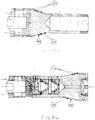
- the present invention relates to at least one hybrid engine with at least two hybrid pistons, conjugating at least two energies, propelled by a fluid in pressure and flow rate, each piston is assembled and mounted in at least one ring positioned at least between two shirts with at least one closure cap, ( Fig01 to 30 ).
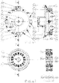
- It consists of at least two circular detection half-cams of 240 ° fixed on the flywheel of the hybrid engine ( Fig31 and Fig32 ), by at least two hydraulic units ( Fig37 to 40 ) mechanically controlled or electro-mechanical devices and of which at least one heat exchanger consisting of at least three parts ( Fig35 and Fig36 ) is used to cool at least one hydraulic unit and to produce heating, the particularity of which is to be designed in such a way that the inner shapes of the two inner parts of the heat exchanger will be machined or cast and cast less the shape of the outer body of at least one hydraulic pump of all types, to allow the attachment of the heat exchanger on the outer body of the latter, but this hydraulic pump can be designed also with a double body molded and poured raw casting, with a first body or circulates a fluid in pressure and flow and in the second outer body or circulates a second fluid to produce heating.
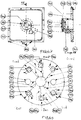
- the device according to the invention is particularly intended for hybrid engines, heating and other industrial concepts such as drone design ( Fig41 to 47 ), stationary or able to move along the six axes, from North to South, from East to West and from top to bottom or vice versa, technology that will be used in all areas of transport to move a bicycle, a motorcycle, a vehicle etc ..., but also to drive any mechanical system or other.
- drone design Fig41 to 47
- stationary or able to move along the six axes from North to South, from East to West and from top to bottom or vice versa
- technology that will be used in all areas of transport to move a bicycle, a motorcycle, a vehicle etc ..., but also to drive any mechanical system or other.
- Heat engines and heating systems are traditionally polluting and energy consumers, they do not always or hardly respond to the co 2 regulation, because the context of increasing environmental concerns and strengthening requirements for sustainable development, at the international level by the Kyoto Protocol and COP 21 in Paris have set targets and agreements for the reduction of greenhouse gases and pollution co 2 , the energy bill represents 88% of the trade deficit of the France, not to mention peaks in energy consumption, which confirms that energy savings and renewable energies are the two priority areas of energy policy, forcing manufacturers of heat engines, radiators and boilers to central heating, to review their strategies and improvements in terms of longevity, noise pollution of pollution and energy saving, which to date are difficult to achieve due to costs and constraints, although the OECD encourages governments to use tax schemes to stimulate environmental innovation .
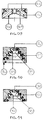
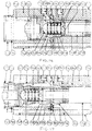
- the devices according to the invention make it possible to remedy these drawbacks. It comprises in fact according to a first characteristic a first assembly comprising at least one hybrid engine with at least two hybrid pistons, conjugating at least two energies, propelled by a fluid in pressure and flow rate, each piston is assembled and mounted in at least one ring positioned at least between two jackets or at least incorporated in the machining of one of the two jackets, with at least one closure cap, with at least one first piston in top dead center (21) in the first neutral point jacket top (11) which will be propelled towards the bottom dead center in the first bottom dead center (01), driving the second piston in low dead point composed of the piston foot (82) screwed into the piston head (83) which is therefore found at the end of the propulsion action of the first piston in top dead center (21), in the bottom dead center position in the second bottom dead center (61) to be in turn propelled towards the top dead center in the two the top dead center shirt (74) and so on in the same manner and which are equipped, for the first top dead center piston (21) and the
- the second piston in bottom dead center composed of the piston foot (82) screwed into the head piston (83), whose particularity of the foot and the piston head are to be provided with machined grooves, which will receive at least one seal and at least one sealing and guiding segment
- the diameter of the second piston head in low dead point (83) corresponds to the fourth bore (77) of the second top deadlock (74)
- the diameter of the piston pin (82) corresponds to the bore of the second point jacket low dead (61), whose piston foot design is standard to all existing pistons and whose diameter of the piston foot (82) of the second piston in low dead point must always be smaller than the diameter of the piston head ( 83) of the second piston in low dead point, to form with the fifth bore (77), the sixth cylindrical or slightly conical bore (72) having the same slope as the second conical surface (71), at least one sixth expansion chamber and propulsion (
- the particularity of the first threaded bore (60) and the second threaded bore (101) are to allow to purge and expel the air in all the expansion chambers and propulsion before operation, it will plug these holes tapped by grub screws headless .
- the third conical surface (58), the fourth conical surface (115), the fifth conical surface (100) and the sixth conical surface (135) make it possible to increase the thrust force on these conical surfaces by the action of the fluid. pressure and flow.
- 45 ° circular rounded bottom grooves in the form of a staircase are made and machined on the first top dead center piston (21) and on the second bottom dead center piston consisting of the piston foot (82) screwed into the head of the piston (83), according to the first 45 ° circular rounded bottom grooves in the form of a staircase (112), the second 45 ° circular rounded bottom grooves in the form of a staircase (114), the third circular circular grooves 45 ° with a rounded bottom in the form of a staircase (137) and the fourth circular grooves at 45 ° with a rounded bottom in the form of a staircase (139) also for the purpose of increasing the thrust force on these surfaces by the action of the fluid in pressure and flow.
- At least one twelfth ring (85) and at least one thirteenth ring (84) will also have bleeds 45 ° circular rounded bottom shaped staircase which are made and machined inside the twelfth ring (85) and the thirteenth ring (84) following the fifth 45 ° circular rounded bottom grooves in the form of staircase (95) and the sixth 45 ° circular rounded bottom grooves in the form of a staircase (99), the other 45 ° circular rounded bottom grooves in the form of a staircase will also be produced and machined in the same way according to the Fig.05 and 06 .
- the ( Fig33 ) and Fig34 ) show other forms made and machined according to the first forms designed in steps with steps and against steps (270) or the second forms with hollow waves and against steps (271) on the first piston in top dead center (21) and according to the third forms designed in steps with steps and against steps (272) or the fourth forms with hollow waves and against steps (273) on the second piston in low dead point composed of the piston foot (82) screwed into the piston head (83).
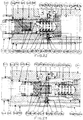
- the hybrid engine with at least two hybrid pistons, conjugating at least two energies propelled by a fluid under pressure and flow rate, each piston of which is assembled and mounted in at least one ring positioned at least between two jackets with at least one closure cap and at least one first 240 ° circular detection half-cams (260) and a second half-cams 240 ° circular detection (265) attached to the hybrid engine flywheel ( Fig31 and Fig32 ) each having at least a first detection track (261) and a second detection track (266), which allow direct or indirect action via at least one roller on at least one first hydraulic apparatus mechanical control ( Fig37 ) by detection track or by at least a first device with electro-mechanical control by detection track for supplying at least the coil of a first hydraulic apparatus for conveying the fluid under pressure and flow to at least a first expansion chamber and propulsion (174) at least one first top dead center piston (168), assembled and mounted in at least one
- At least one first top dead center piston (168) in the first top dead center (156) will be propelled to bottom dead center in the first bottom dead center (143), driving the second piston to bottom dead point (226). ) which is therefore at the end of the propulsion action of the first piston in top dead center (168), in the bottom dead center position in the second bottom dead center (198) to be in turn propelled towards the top dead center in the second top dead center (214) and so on in the same manner and which are equipped for the first top dead piston (168) and the second bottom dead center piston (226), of a piston head and a piston foot, the particularity of which is to be provided with machined grooves, which will receive at least one seal and at least one sealing and guiding segment, the first diameter of the head of the first piston in top dead center (168) corresponds to the first bore (159) of e the first top deadlayer (156) and the second root diameter of the latter corresponds to the second bore (147) of the first bottom neutral case (143), the piston foot design of which is standard to all pistons existing and whose second diameter
- the second piston in low dead point (226) its particularity is to be designed in two parts, with a piston foot which is screwed into the head of the latter and locked in rotation, to mount and in the fifth ring (224) positioned between the second bottom dead center (198) and the second top dead center (214), the fifth diameter of the second piston head in bottom dead point (226) matches and slides in the third bore (218) of the second top deadlock (214) and the sixth diameter of the bottom thereof corresponds and slides in the fourth bore (205) of the second bottom neutral case (198), whose design the piston foot is standard to all existing pistons, but the sixth diameter of the piston foot must always be less than the fifth diameter of the second piston head in low dead point (226), to develop at least a seventh diameter exterior with a conical surface (241) and at least a fourth expansion and propulsion chamber (228), whose shape is defined by the smallest volume by at least one second bottom dead center (198) and at least one fifth ring (224) with an eighth inner diameter having at least one surface of the same conicity
- the first ring (167) shows a fourth internal diameter with a machined conical surface (192), which will seal with the third outer diameter of the machined conical surface (187) of the first top dead center piston (168).
- the second assembly comprises the second bottom dead center (198), second top dead center (214), second bottom dead center (226) and second ring (224) ( fig22 ), has this second piston in the bottom dead position, whose particularity is to be provided with a fourth cylindrical groove (210) on the second bottom dead center (198), a fifth cylindrical groove (250) on the second ring (224) and a sixth cylindrical groove (201) on the second bottom dead center (198) which will receive a seal to seal, a second cylindrical flat seal (211) between the second neutral point bottom (198) and the second top dead center shirt (214) will strengthen the seal.
- the second ring (224) shows a fifth internal diameter with a machined conical surface (225), reverses the fourth internal diameter of the machined conical surface (192) of the first ring (167) which will seal with the outer diameter of the conical surface machined (241) of the second low dead center piston (226) between the fourth expansion and propulsion chamber (228) and the fifth expansion and propulsion chamber (229) of the second bottom dead center (198) and the second top dead center shirt (214).
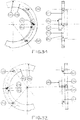
- a first detection half-cam (260) and a second half-cam (265) of circular shape at 240 ° ( Fig31 to Fig32 ) after adjustment are fixed on the engine flywheel, a first pin (264) fixed on the first half-cam (260) and a second pin (269) fixed on the second half-cam (265) can be slid into circular grooves positioned on the flywheel to allow adjustment in position of the first detection track (261) and the second detection track (266) relative to the top and bottom dead center of the first piston in top dead center (168) ) and the second bottom dead center piston (226) of at least one hybrid two-cylinder engine and at least one first and second hydraulic units ( Fig37 ) with mechanical control or electromagnetic coil control, the particularity of the first and second half-cam are to be provided with a first and second detection track independent of one another and parallel, of which the one corresponds to the position of the first piston in top dead point (168) and the other to the second piston in bottom dead point (226) according to their position in low or high dead point,
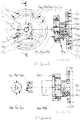
- the first and second heat exchanger ( Fig35 to Fig36 ) is composed of at least three parts, a first part (274), a second part (285) and a third part (280), the particularity of which of the first part (274) is to be an outer body shaped machined crown and mounted with a tight fit to the non-removable nitrogen on the second part (285), to ensure complete sealing after assembly, this first part (274) is provided with a first threaded inlet bore (275) which will receive a connection and a pipe, from which the fluid will come, this first part will have several first fins machined (276), which will be adjusted with clearance in the first partition (278) fluid circulation of the second portion (285), these first fins (276) will be pierced by a plurality of first holes (277), these first machined fins (276) and first bores (277) will allow the flow of fluid through the first tapped entry holes (275) to the second tapped output bore (279), the second portion (285) is provided with a first circular groove
- An additional fourth part (288) can be added to increase the heat capacity and heat output of this second heat exchanger, the particularity of which is that of the fourth additional portion (288) being machined and mounted with a snug fit to the non-removable nitrogen on the first portion (274), to ensure complete sealing after assembly, this fourth additional portion is provided with a third threaded entry bore (289) which will receive a fitting and a pipe from which will come the fluid, this fourth additional portion (288) will have several second fins (290) machined which will be adjusted with clearance in the second partition (292) fluid circulation, these second fins (290) will be pierced by a plurality of third holes (291), these second fins (290) and these third holes (291) will allow the flow of fluid through the third tapped hole of entered e (289) to the fourth threaded outlet bore (293) which will receive a fitting and piping from which the fluid will exit, a second additional groove on the third portion (280) may be made and machined in the same manner as the circular groove (282)
- each piston is assembled and mounted in at least one ring positioned at least between two shirts with at least one hat closing, with at least two identical hydraulic devices per assembly, the particularity of which for the first or second hydraulic apparatus is to allow the pressurization and flow of a circuit by the alignment and the intermediate of the first threaded bore (299) the first body (294), the first bore (309) of the first axis (305) and the second tapping hole (302) of the first body (294), when the first axis (305) is actuated by a mechanical roller system ( 306) or the like or by an apparatus with an electromagnetic coil opening the circuit and when the first axis (305) is no longer actuated and returns to the rest position via an internal pilot communicating via the first tapping hole (299).
- the translation and rotational locking of the first axis (305) is effected by means of the second groove (308) of the first axis (305) and a pin screw screwed into the first body (294).
- third grooves (311) on the first axis (305) seal with seals with the first bore (296), the second bore (297) of the first body (294) and the bore of the first plug ( 304) or slides the first axis (305) whose first plug is screwed into the first body (294) via the sixth threaded bore (298), the fourth threaded bore (301) communicates with the bore of the first plug (304) or slides the first axis (305) to push the latter in the rest position, the first circular housing (295) in the first body (294) seals by a seal between the first axis (305) and the first body (294).
- a first drone Fig41 to 44
- a first boss will make a first tapping hole (314) 45 ° inwardly of the first body (312)
- the third tapping hole (318) corresponds to the suction of the hydraulic pump in the low position, defining the volume by the second bore (319)
- first fixing lugs (317) will fix the first body (312) on all supports
- the fourth tapping holes (316) will fix the first closure plate (328), a first wheel (322) whose material is as light as possible while having the highest mechanical strength , first hollow centering foot (323) mounted in circumferentially positioned, circumferentially positioned
- the first cap (328) is attached to the first body (312) through the first holes (345), a second boss (329) will provide a fourth tapping hole (331) at 45 ° to the inside of the first body (312), a third boss (330) will provide a fifth tapping hole (332) at 90 ° which opens along the circumference of the fourth bore (334), the fifth bore (337) will receive at its bottom a seal sealing and will center and mount the first cap (328) on the first body (312), a third circular groove (338) and a fourth circular groove (340) will receive a seal and at least three fifth circular grooves ( 336) made and machined in the sixth bore (333) will receive at least one seal and at least one segment, for sealing between the first shaft of the first alternator (344) and the sixth bore (333), at less than four e sixth tapping holes (339) and the first bores (545) will fix the first
- an eighth tapping hole (353) at 45 ° to the inside of the second body (346) opens into the eighth bore (348)
- the ninth tapping bore (352) on the second body (346) opens into the tenth tapping hole (353) and also communicates with the eleventh tapping bore (349) which will receive a connector and piping for conveying the fluid under pressure and flow
- all the twelfth threaded holes (350) communicate with all eleventh threaded holes (349), all of which will receive a connector and piping for conveying the fluid under pressure and flow and open and communicate with all second holes (351) which are obtained by drilling or casting at the molding and casting of the second body (346) all these second per holes (351) open into all third circular vee (354) machined and made in the eighth bore (348)
- the second cap (362) is attached to the second body (346) through the third bores (368) and fourteenth bore tapping (357), a fourth boss (366) will provide a fifteenth tapping hole (367) at 90 ° to the interior of the second body (346) and leading to the circumference of the eleventh bore (365), a sixth circular groove (372) will receive a seal and at least one seventh circular groove (369).
- the second closing cap (362) will be fixed on the second body (346) and which is equipped with a second alternator fixed via the seventh holes (371) with a fourth wheel identical to the second wheel (341). ) and which will also be rotated by a fluid in pressure and flow.
- the same principle and design can be adopted as the first closure cap (328) with the first alternator (344) and the second wheel (341), without the second boss (329) and the fourth tapping hole (331) but the plate closure will have the same square shape as the second closure cap (362).
- the ( Fig48 ) represents the schematic of a set of drones may remain stationary or move north or south, east or west and up or down, defining Fig48 ) a support receiving in the north and south axis two UAVs (373) in opposition of inertia, each equipped with an alternator (344) and a pressure reducer (374) which will be adjusted to an equivalent defined pressure, but which will be opposed developing a tangential inertia which is transformed into opposite directional displacement, maintaining the North-South position in stationary of the two drones, it is therefore sufficient to vary the pressure and the flow on one of the pressure reducers (374) of the drone North or South to define the direction of the displacement to the North or the South, PWR coils, which will allow to vary the pressure and the flow, according to the electric tension sent on the coils PWR
- the devices according to the invention are particularly intended for the hybrid engine with at least two hybrid pistons, conjugating at least two energies, propelled by a fluid in pressure and flow rate, each piston is assembled and mounted in at least one ring positioned at least between two folders or incorporated in the machining of at least one of the two folders with at least one closure cap, ( Fig01 to 30 ).
- It consists of at least two circular detection half-cams of 240 ° fixed on the flywheel of the hybrid engine ( Fig31 and Fig32 ), by at least two hydraulic units ( Fig37 to 40 ) mechanically controlled or electro-mechanical devices and of which at least one heat exchanger consisting of at least three parts ( Fig35 and Fig36 ) can cool at least one hydraulic unit and produce heating, the particularity of which is to be designed so that the internal shapes of the two inner parts of the heat exchanger will be machined or molded and poured gross casting to fit at least the shape of the outer body of at least one hydraulic pump of all types, to allow the attachment of the heat exchanger on the outer body of the latter, but this hydraulic pump can also be designed with a double cast body and cast raw casting, with a first body or circulates a fluid pressure and flow and in the second outer body or circulates a second fluid to produce heating.
Landscapes
- Engineering & Computer Science (AREA)
- General Engineering & Computer Science (AREA)
- Mechanical Engineering (AREA)
- Chemical & Material Sciences (AREA)
- Combustion & Propulsion (AREA)
- Reciprocating Pumps (AREA)
- Air-Conditioning For Vehicles (AREA)
Applications Claiming Priority (16)
| Application Number | Priority Date | Filing Date | Title |
|---|---|---|---|
| FR1600157A FR3036747A1 (fr) | 2015-05-31 | 2016-01-29 | Moteur hybride a pistons propulses par un fluide en pressions et debit et ses chemises dotes de chambre de detentes et ses systemes de chauffage |
| FR1600848A FR3037362A1 (fr) | 2015-05-31 | 2016-05-26 | Moteur hybride a pistons hybride propulses par un fluide en pression et debit et un drone a deplacements nord ou sud, est ou ouest et haut ou bas et stationnaire |
| IB2016000725 | 2016-05-27 | ||
| IB2016000880 | 2016-06-24 | ||
| EP16001417 | 2016-06-24 | ||
| IB2016001037 | 2016-07-22 | ||
| EP16001833 | 2016-08-19 | ||
| IB2016001151 | 2016-08-19 | ||
| EP16002017 | 2016-09-16 | ||
| IB2016001365 | 2016-09-16 | ||
| IB2016001483 | 2016-10-14 | ||
| EP16002209 | 2016-10-14 | ||
| EP16002380 | 2016-11-11 | ||
| IB2016001636 | 2016-11-11 | ||
| EP16002626 | 2016-12-09 | ||
| IB2016001777 | 2016-12-09 |
Publications (2)
| Publication Number | Publication Date |
|---|---|
| EP3205815A2 true EP3205815A2 (de) | 2017-08-16 |
| EP3205815A3 EP3205815A3 (de) | 2017-11-01 |
Family
ID=57799530
Family Applications (1)
| Application Number | Title | Priority Date | Filing Date |
|---|---|---|---|
| EP17000018.6A Withdrawn EP3205815A3 (de) | 2016-01-29 | 2017-01-06 | Hybridmotor mit hybridkolben, die angetrieben werden durch eine druck- und durchsatzgetriebene flüssigkeit, und drohne mit nord- oder süd-, ost- oder westbewegungen sowie bewegungen nach oben und unten und in stationärer positionshaltung |
Country Status (1)
| Country | Link |
|---|---|
| EP (1) | EP3205815A3 (de) |
Cited By (1)
| Publication number | Priority date | Publication date | Assignee | Title |
|---|---|---|---|---|
| CN114050333A (zh) * | 2022-01-13 | 2022-02-15 | 西安迈远科技有限公司 | 一种应用于植保设备的电池及无人机 |
Family Cites Families (3)
| Publication number | Priority date | Publication date | Assignee | Title |
|---|---|---|---|---|
| US6200103B1 (en) * | 1999-02-05 | 2001-03-13 | Robert E. Bender | Gas lift plunger having grooves with increased lift |
| FR2919022B1 (fr) * | 2007-07-19 | 2012-10-26 | Vianney Rabhi | Centrale hydraulique pour moteur a taux de compression variable. |
| FR3002292A1 (fr) * | 2012-11-15 | 2014-08-22 | Patrick Marcel Strzyzewski | Chauffage et moteur avec pistons propulses par pression et debit hydraulique, outillage de montage, refroidissement par echangeur thermique obligatoire, produit du chauffage et de l'electricite |
-
2017
- 2017-01-06 EP EP17000018.6A patent/EP3205815A3/de not_active Withdrawn
Non-Patent Citations (1)
| Title |
|---|
| None |
Cited By (2)
| Publication number | Priority date | Publication date | Assignee | Title |
|---|---|---|---|---|
| CN114050333A (zh) * | 2022-01-13 | 2022-02-15 | 西安迈远科技有限公司 | 一种应用于植保设备的电池及无人机 |
| CN114050333B (zh) * | 2022-01-13 | 2022-04-22 | 西安迈远科技有限公司 | 一种应用于植保设备的电池及无人机 |
Also Published As
| Publication number | Publication date |
|---|---|
| EP3205815A3 (de) | 2017-11-01 |
Similar Documents
| Publication | Publication Date | Title |
|---|---|---|
| CA2929855C (fr) | Appareil thermique magnetocalorique | |
| US5938224A (en) | Hydraulic bicycle with conjugate drive motors and variable stroke crankshaft | |
| WO2010061064A1 (fr) | Generateur thermioue a materiau magnetocalorioue | |
| WO2009098391A1 (fr) | Generateur magnetocalorique | |
| EP2596212A1 (de) | Hydraulikmotor und strom-, luft-, klimatisierungs- sowie wärmeerzeugung | |
| WO2013060946A1 (fr) | Generateur thermique magnetocalorique | |
| EP2361442A1 (de) | Magnetokalorischer w?rmegenerator | |
| CA2916005A1 (fr) | Dispositif de compression thermique de fluide gazeux | |
| US6612117B2 (en) | Hydristor heat pump | |
| WO2006010863A1 (fr) | Chemise de refroidissement pour une machine rotative et machine rotative comportant une telle chemise de refroidissement | |
| EP3205815A2 (de) | Hybridmotor mit hybridkolben, die angetrieben werden durch eine druck- und durchsatzgetriebene flüssigkeit, und drohne mit nord- oder süd-, ost- oder westbewegungen sowie bewegungen nach oben und unten und in stationärer positionshaltung | |
| EP3557081A1 (de) | Brennstoffzelle, die einen fluidverdichter umfasst | |
| WO2017130049A2 (fr) | Moteur hybride à pistons hybride propulsés par un fluide en pression et débit et un drone à déplacement nord ou sud, est ou ouest et haut ou bas et stationnaire | |
| FR3037362A1 (fr) | Moteur hybride a pistons hybride propulses par un fluide en pression et debit et un drone a deplacements nord ou sud, est ou ouest et haut ou bas et stationnaire | |
| EP3087329B1 (de) | Magnetokalorischer wärmegenerator und verfahren zur kühlung davon | |
| WO2008053089A1 (fr) | Vanne thermostatique multivoies pour la distribution selective et la regulation de debit d'un liquide de refroidissement dans un circuit de refroidissement d'un moteur de vehicule automobile | |
| WO2008075142A1 (fr) | Moteur a aimants permanents sous l'impulsion d ' une pompe a vide | |
| FR2917548A1 (fr) | Moteur temporel a variation de vitesse | |
| EP2972045A2 (de) | Thermische vorrichtung | |
| FR2874061A1 (fr) | Dispositif a diffuseur interne au rotor permettant de transf ormer l'energie hydraulique en un mouvement rotatif | |
| WO2019105897A1 (fr) | Systeme d'embrayage humide alimente en fluide par un canal forme entre deux manchons | |
| FR2662468A1 (fr) | Moteur thermique rotatif modulaire. | |
| FR2561316A1 (fr) | Systeme transformateur d'energie mecanique applicable notamment aux eoliennes | |
| EP3177879A1 (de) | Wärmekraftmaschine mit magnetokalorischem material vom kältemaschinen- oder wärmepumpentyp | |
| FR2977273A1 (fr) | Dispositif de reglage du dephasage angulaire relatif entre manetons de vilebrequins |
Legal Events
| Date | Code | Title | Description |
|---|---|---|---|
| PUAI | Public reference made under article 153(3) epc to a published international application that has entered the european phase |
Free format text: ORIGINAL CODE: 0009012 |
|
| STAA | Information on the status of an ep patent application or granted ep patent |
Free format text: STATUS: THE APPLICATION HAS BEEN PUBLISHED |
|
| AK | Designated contracting states |
Kind code of ref document: A2 Designated state(s): AL AT BE BG CH CY CZ DE DK EE ES FI FR GB GR HR HU IE IS IT LI LT LU LV MC MK MT NL NO PL PT RO RS SE SI SK SM TR |
|
| AX | Request for extension of the european patent |
Extension state: BA ME |
|
| PUAL | Search report despatched |
Free format text: ORIGINAL CODE: 0009013 |
|
| AK | Designated contracting states |
Kind code of ref document: A3 Designated state(s): AL AT BE BG CH CY CZ DE DK EE ES FI FR GB GR HR HU IE IS IT LI LT LU LV MC MK MT NL NO PL PT RO RS SE SI SK SM TR |
|
| AX | Request for extension of the european patent |
Extension state: BA ME |
|
| RIC1 | Information provided on ipc code assigned before grant |
Ipc: F01B 17/02 20060101AFI20170928BHEP |
|
| STAA | Information on the status of an ep patent application or granted ep patent |
Free format text: STATUS: REQUEST FOR EXAMINATION WAS MADE |
|
| 17P | Request for examination filed |
Effective date: 20180404 |
|
| RBV | Designated contracting states (corrected) |
Designated state(s): AL AT BE BG CH CY CZ DE DK EE ES FI FR GB GR HR HU IE IS IT LI LT LU LV MC MK MT NL NO PL PT RO RS SE SI SK SM TR |
|
| STAA | Information on the status of an ep patent application or granted ep patent |
Free format text: STATUS: EXAMINATION IS IN PROGRESS |
|
| 17Q | First examination report despatched |
Effective date: 20180829 |
|
| RAP1 | Party data changed (applicant data changed or rights of an application transferred) |
Owner name: STRZYZEWSKI, PATRICK |
|
| RIN1 | Information on inventor provided before grant (corrected) |
Inventor name: STRZYZEWSKI, PATRICK |
|
| STAA | Information on the status of an ep patent application or granted ep patent |
Free format text: STATUS: THE APPLICATION IS DEEMED TO BE WITHDRAWN |
|
| 18D | Application deemed to be withdrawn |
Effective date: 20210803 |