EP3205860A1 - Elektropneumatisches gasturbinenmotormotorisierungssystem für starts von motoren mit gebogenem rotor - Google Patents
Elektropneumatisches gasturbinenmotormotorisierungssystem für starts von motoren mit gebogenem rotor Download PDFInfo
- Publication number
- EP3205860A1 EP3205860A1 EP17155902.4A EP17155902A EP3205860A1 EP 3205860 A1 EP3205860 A1 EP 3205860A1 EP 17155902 A EP17155902 A EP 17155902A EP 3205860 A1 EP3205860 A1 EP 3205860A1
- Authority
- EP
- European Patent Office
- Prior art keywords
- electro
- engine
- starter
- drive motor
- electric drive
- Prior art date
- Legal status (The legal status is an assumption and is not a legal conclusion. Google has not performed a legal analysis and makes no representation as to the accuracy of the status listed.)
- Granted
Links
Images


Classifications
-
- F—MECHANICAL ENGINEERING; LIGHTING; HEATING; WEAPONS; BLASTING
- F02—COMBUSTION ENGINES; HOT-GAS OR COMBUSTION-PRODUCT ENGINE PLANTS
- F02C—GAS-TURBINE PLANTS; AIR INTAKES FOR JET-PROPULSION PLANTS; CONTROLLING FUEL SUPPLY IN AIR-BREATHING JET-PROPULSION PLANTS
- F02C7/00—Features, components parts, details or accessories, not provided for in, or of interest apart form groups F02C1/00 - F02C6/00; Air intakes for jet-propulsion plants
- F02C7/26—Starting; Ignition
- F02C7/268—Starting drives for the rotor, acting directly on the rotor of the gas turbine to be started
- F02C7/27—Fluid drives
-
- F—MECHANICAL ENGINEERING; LIGHTING; HEATING; WEAPONS; BLASTING
- F01—MACHINES OR ENGINES IN GENERAL; ENGINE PLANTS IN GENERAL; STEAM ENGINES
- F01D—NON-POSITIVE DISPLACEMENT MACHINES OR ENGINES, e.g. STEAM TURBINES
- F01D25/00—Component parts, details, or accessories, not provided for in, or of interest apart from, other groups
- F01D25/08—Cooling; Heating; Heat-insulation
- F01D25/12—Cooling
-
- F—MECHANICAL ENGINEERING; LIGHTING; HEATING; WEAPONS; BLASTING
- F01—MACHINES OR ENGINES IN GENERAL; ENGINE PLANTS IN GENERAL; STEAM ENGINES
- F01D—NON-POSITIVE DISPLACEMENT MACHINES OR ENGINES, e.g. STEAM TURBINES
- F01D15/00—Adaptations of machines or engines for special use; Combinations of engines with devices driven thereby
- F01D15/10—Adaptations for driving, or combinations with, electric generators
-
- F—MECHANICAL ENGINEERING; LIGHTING; HEATING; WEAPONS; BLASTING
- F01—MACHINES OR ENGINES IN GENERAL; ENGINE PLANTS IN GENERAL; STEAM ENGINES
- F01D—NON-POSITIVE DISPLACEMENT MACHINES OR ENGINES, e.g. STEAM TURBINES
- F01D19/00—Starting of machines or engines; Regulating, controlling, or safety means in connection therewith
- F01D19/02—Starting of machines or engines; Regulating, controlling, or safety means in connection therewith dependent on temperature of component parts, e.g. of turbine-casing
-
- F—MECHANICAL ENGINEERING; LIGHTING; HEATING; WEAPONS; BLASTING
- F02—COMBUSTION ENGINES; HOT-GAS OR COMBUSTION-PRODUCT ENGINE PLANTS
- F02C—GAS-TURBINE PLANTS; AIR INTAKES FOR JET-PROPULSION PLANTS; CONTROLLING FUEL SUPPLY IN AIR-BREATHING JET-PROPULSION PLANTS
- F02C7/00—Features, components parts, details or accessories, not provided for in, or of interest apart form groups F02C1/00 - F02C6/00; Air intakes for jet-propulsion plants
- F02C7/26—Starting; Ignition
- F02C7/268—Starting drives for the rotor, acting directly on the rotor of the gas turbine to be started
- F02C7/275—Mechanical drives
- F02C7/277—Mechanical drives the starter being a separate turbine
-
- F—MECHANICAL ENGINEERING; LIGHTING; HEATING; WEAPONS; BLASTING
- F02—COMBUSTION ENGINES; HOT-GAS OR COMBUSTION-PRODUCT ENGINE PLANTS
- F02C—GAS-TURBINE PLANTS; AIR INTAKES FOR JET-PROPULSION PLANTS; CONTROLLING FUEL SUPPLY IN AIR-BREATHING JET-PROPULSION PLANTS
- F02C7/00—Features, components parts, details or accessories, not provided for in, or of interest apart form groups F02C1/00 - F02C6/00; Air intakes for jet-propulsion plants
- F02C7/36—Power transmission arrangements between the different shafts of the gas turbine plant, or between the gas-turbine plant and the power user
-
- F—MECHANICAL ENGINEERING; LIGHTING; HEATING; WEAPONS; BLASTING
- F02—COMBUSTION ENGINES; HOT-GAS OR COMBUSTION-PRODUCT ENGINE PLANTS
- F02N—STARTING OF COMBUSTION ENGINES; STARTING AIDS FOR SUCH ENGINES, NOT OTHERWISE PROVIDED FOR
- F02N11/00—Starting of engines by means of electric motors
- F02N11/08—Circuits specially adapted for starting of engines
- F02N11/0859—Circuits specially adapted for starting of engines specially adapted to the type of the starter motor or integrated into it
-
- F—MECHANICAL ENGINEERING; LIGHTING; HEATING; WEAPONS; BLASTING
- F02—COMBUSTION ENGINES; HOT-GAS OR COMBUSTION-PRODUCT ENGINE PLANTS
- F02N—STARTING OF COMBUSTION ENGINES; STARTING AIDS FOR SUCH ENGINES, NOT OTHERWISE PROVIDED FOR
- F02N11/00—Starting of engines by means of electric motors
- F02N11/08—Circuits specially adapted for starting of engines
- F02N11/0862—Circuits specially adapted for starting of engines characterised by the electrical power supply means, e.g. battery
-
- F—MECHANICAL ENGINEERING; LIGHTING; HEATING; WEAPONS; BLASTING
- F05—INDEXING SCHEMES RELATING TO ENGINES OR PUMPS IN VARIOUS SUBCLASSES OF CLASSES F01-F04
- F05D—INDEXING SCHEME FOR ASPECTS RELATING TO NON-POSITIVE-DISPLACEMENT MACHINES OR ENGINES, GAS-TURBINES OR JET-PROPULSION PLANTS
- F05D2220/00—Application
- F05D2220/50—Application for auxiliary power units (APU's)
-
- F—MECHANICAL ENGINEERING; LIGHTING; HEATING; WEAPONS; BLASTING
- F05—INDEXING SCHEMES RELATING TO ENGINES OR PUMPS IN VARIOUS SUBCLASSES OF CLASSES F01-F04
- F05D—INDEXING SCHEME FOR ASPECTS RELATING TO NON-POSITIVE-DISPLACEMENT MACHINES OR ENGINES, GAS-TURBINES OR JET-PROPULSION PLANTS
- F05D2230/00—Manufacture
- F05D2230/60—Assembly methods
-
- F—MECHANICAL ENGINEERING; LIGHTING; HEATING; WEAPONS; BLASTING
- F05—INDEXING SCHEMES RELATING TO ENGINES OR PUMPS IN VARIOUS SUBCLASSES OF CLASSES F01-F04
- F05D—INDEXING SCHEME FOR ASPECTS RELATING TO NON-POSITIVE-DISPLACEMENT MACHINES OR ENGINES, GAS-TURBINES OR JET-PROPULSION PLANTS
- F05D2260/00—Function
- F05D2260/40—Transmission of power
- F05D2260/403—Transmission of power through the shape of the drive components
- F05D2260/4031—Transmission of power through the shape of the drive components as in toothed gearing
-
- F—MECHANICAL ENGINEERING; LIGHTING; HEATING; WEAPONS; BLASTING
- F05—INDEXING SCHEMES RELATING TO ENGINES OR PUMPS IN VARIOUS SUBCLASSES OF CLASSES F01-F04
- F05D—INDEXING SCHEME FOR ASPECTS RELATING TO NON-POSITIVE-DISPLACEMENT MACHINES OR ENGINES, GAS-TURBINES OR JET-PROPULSION PLANTS
- F05D2260/00—Function
- F05D2260/85—Starting
-
- F—MECHANICAL ENGINEERING; LIGHTING; HEATING; WEAPONS; BLASTING
- F05—INDEXING SCHEMES RELATING TO ENGINES OR PUMPS IN VARIOUS SUBCLASSES OF CLASSES F01-F04
- F05D—INDEXING SCHEME FOR ASPECTS RELATING TO NON-POSITIVE-DISPLACEMENT MACHINES OR ENGINES, GAS-TURBINES OR JET-PROPULSION PLANTS
- F05D2270/00—Control
- F05D2270/01—Purpose of the control system
- F05D2270/11—Purpose of the control system to prolong engine life
- F05D2270/112—Purpose of the control system to prolong engine life by limiting temperatures
-
- Y—GENERAL TAGGING OF NEW TECHNOLOGICAL DEVELOPMENTS; GENERAL TAGGING OF CROSS-SECTIONAL TECHNOLOGIES SPANNING OVER SEVERAL SECTIONS OF THE IPC; TECHNICAL SUBJECTS COVERED BY FORMER USPC CROSS-REFERENCE ART COLLECTIONS [XRACs] AND DIGESTS
- Y02—TECHNOLOGIES OR APPLICATIONS FOR MITIGATION OR ADAPTATION AGAINST CLIMATE CHANGE
- Y02T—CLIMATE CHANGE MITIGATION TECHNOLOGIES RELATED TO TRANSPORTATION
- Y02T50/00—Aeronautics or air transport
- Y02T50/60—Efficient propulsion technologies, e.g. for aircraft
Definitions
- the embodiments herein generally relate to gas turbine engines and more specifically, systems and method for cooling gas turbine engines.
- Pneumatic or Air Turbine Starters are typically duty cycle limited due to lubrication issues and heat dissipation.
- Butterfly type start valves are typically solenoid actuated and have diaphragms and linkage in the actuator piston assembly that are prone to wear if they are being used to modulate and control starter speed. This type of operation decreases the valve and start life significantly. A more efficient method of motoring the gas turbine engine that does not cause excessive wear and tear is desired.
- further embodiments of the engine starting system may include an accessory gearbox operably connecting the electro-pneumatic starter to at least one of the rotational components.
- the electro-pneumatic starter further comprises a turbine wheel including a hub integrally attached to a turbine rotor shaft and a plurality of turbine blades extending radially from the hub, the turbine rotor shaft being operably connected to at least one of the rotational components and configured to rotate the rotational components when air flows through the turbine blades and rotates the turbine wheel.
- further embodiments of the engine starting system may include: an auxiliary power unit fluidly connected to the electro-pneumatic starter and electrically connected to the electric drive motor, the auxiliary power unit being configured to generate electricity to power the electric drive motor and provide air to the electro-pneumatic starter to rotate the turbine blades.
- an engine starting system for a gas turbine engine comprising: obtaining a gas turbine engine including rotational components comprising an engine compressor, an engine turbine, and a rotor shaft operably connecting the engine turbine to the engine compressor, wherein each rotational component is configured to rotate when any one of the rotational components is rotated; operably connecting an electro-pneumatic starter to at least one of the rotational components, the electro-pneumatic starter being configured to rotate the rotational components; operably connecting an electric drive motor to the electro-pneumatic starter, the electric drive motor being configured to rotate the rotational components through the electro-pneumatic starter; and electrically connecting a motor controller to electric drive motor, the motor controller being configured to command the electric drive motor to rotate the rotational components at a selected angular velocity for a selected period of time.
- further embodiments of the method of assembling an engine starting system may include where the electro-pneumatic starter is operably connected to at least one of the rotational components through an accessory gearbox.
- the electro-pneumatic starter further comprises: a turbine wheel including a hub integrally attached to a turbine rotor shaft and a plurality of turbine blades extending radially from the hub, wherein the turbine rotor shaft is configured to rotate the rotational components when air flows through the turbine blades and rotates the turbine wheel.
- further embodiments of the method of assembling an engine starting system may include: fluidly connecting an auxiliary power unit to the electro-pneumatic starter, the auxiliary power unit being configured to provide air to the electro-pneumatic starter to rotate the turbine blades; and electrically connecting the electric drive motor to the auxiliary power unit, the auxiliary power unit being configured to generate electricity to power the electric drive motor.
- a method of cooling a gas turbine engine comprises: rotating, using an electric drive motor, rotational components of a gas turbine engine, the rotational components comprising an engine compressor, an engine turbine, and a rotor shaft operably connecting the engine turbine to the engine compressor; wherein each rotational component is configured to rotate when any one of the rotational components is rotated; wherein the electric drive motor is operably connected to at least one of the rotational components through an electro-pneumatic starter.
- further embodiments of the method of cooling a gas turbine engine may include: stopping the utilization of the electric drive motor to rotate the gas turbine engine when a temperature of the gas turbine engine is less than a selected temperature.
- further embodiments of the method of cooling a gas turbine engine may include: opening a starter air valve after the message has been displayed on the cockpit display, the starter air valve being fluidly connected to the electro-pneumatic starter and configured to provide air to the electro-pneumatic starter.
- inventions of the present disclosure include utilizing an electro-pneumatic starter operably connected to an aircraft main engine for cool-down motoring to prevent bowed rotor.
- Embodiments are related to a bowed rotor start mitigation system in a gas turbine engine.
- Embodiments can include using an electro-pneumatic starter to control a rotor speed of a gas turbine engine to mitigate a bowed rotor condition using a cool-down motoring process.
- Cool-down motoring may be performed by running an engine starting system at a lower speed with a longer duration than typically used for engine starting using an electro-pneumatic starter to maintain a rotor speed and/or profile.
- Cool-down motoring (engine bowed rotor motoring) may be performed by the electro-pneumatic starter, which may rotate the gas turbine engine continuously between about 0 to 3000 RPM (engine core speed).
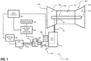
- FIG. 1 shows a block diagram of a gas turbine engine 250 and an associated engine starting system 100 with a valve system 101 according to an embodiment of the present disclosure.
- the valve system 101 includes a starter air valve (SAV) 116 operably connected in fluid communication with an electro-pneumatic starter (EPS) 120 of the engine starting system 100 through at least one duct 140.
- SAV starter air valve
- EPS electro-pneumatic starter
- the valve system 101 is operable to receive a compressed air flow from a compressed air source through one or more ducts 145.
- the compressed air source is an auxiliary power unit (APU) 114.
- the compressed air source may also be a ground cart or a cross-engine bleed.
- An electronic engine controller 320 typically controls engine starting system 100, the gas turbine engine 250, and controls performance parameters of the gas turbine engine 250 such as for example engine temperature, engine, speed, and fuel flow.
- the electronic engine controller 320 may include at least one processor and at least one associated memory comprising computer-executable instructions that, when executed by the processor, cause the processor to perform various operations.
- the processor may be but is not limited to a single-processor or multi-processor system of any of a wide array of possible architectures, including FPGA, central processing unit (CPU), ASIC, digital signal processor (DSP) or graphics processing unit (GPU) hardware arranged homogenously or heterogeneously.
- the memory may be a storage device such as, for example, a random access memory (RAM), read only memory (ROM), or other electronic, optical, magnetic or any other computer readable medium.
- the electric engine controller 320 controls valve operation, for instance, modulation of the starter air valve 116 to control a motoring speed of the gas turbine engine 250 during cool-down motoring.
- the starter air valve 116 delivers air through a duct 140 to the electro-pneumatic starter 120. If the starter air valve 116 fails shut, a corresponding manual override 150 can be used to manually open the starter air valve 116.
- the manual override 150 can include a tool interface 152 to enable a ground crew to open the starter air valve 116.
- the starter air valve 116 may be opened and closed using a solenoid 154.
- the solenoid 154 may be modulated to control a motoring speed of the gas turbine engine 250 during cool-down motoring.
- the solenoid 154 may be in electrical communication with the electronic engine controller 320.
- the motoring speed of the gas turbine engine 250 may also be controlled by an electric drive motor 500.
- the electric drive motor 500 may be operably connected to the pneumatic starter 120 in such a way that the electric drive motor 500 drives the pneumatic starter 120.
- an electric drive motor 500 may be utilized for cool-down motoring in many scenarios including but not limited to when the solenoid 154 fails and can no longer modulate the starter air valve 116 for cool-down motoring.
- the electronic engine controller 320 may transmit a message to be displayed on a cockpit display 320 indicating that a manual start is required.
- the electric drive motor 500 could drive the electro-pneumatic starter 120 to motor the gas turbine engine 250 until it is cooled and then the electronic engine controller 320 could provide a cockpit message to the cockpit display 430 indicating when the engine is cooled sufficiently to allow a crew member to manually open the starter air valve 116 using the manual override 150 and start the gas turbine engine 250.
- the electric drive motor 500 may be used regularly for cool-down motoring in order to reduce wear-tear on the starter air valve 116 and associated solenoid 154 that may be caused by the modulation of the starter air valve 116 when the starter air valve 116 performs cool down motoring.
- the electric drive motor 500 may be used as the primary means to the drive electro-pneumatic starter 120 for motoring the gas turbine engine 250 and the starter air valve 116 may be used as secondary means to drive the electro-pneumatic starter 120 for motoring the gas turbine engine 350 or vice versa.
- the electric drive motor 500 and the starter air valve 116 may also be used in combination with each other to drive the electro-pneumatic starter 120 and motor the gas turbine engine 350.
- the electric drive motor 500 is operably connected through the electro-pneumatic starter 120 to at least one of the rotational components 260 of the gas turbine engine 250.
- the electro-pneumatic starter 120 and accessory gear box 70 may be operably connected the electric drive motor 500 to at least one of the rotational components 260 of the gas turbine engine 250.
- the rotational components 260 may include but are not limited to the engine compressor 265, the engine turbine 258, and the rotor shaft 259 operably connecting the engine turbine 258 to the engine compressor 256.
- Each rotational component 260 is configured to rotate when any one of the rotational components 260 is rotated, thus the rotation components may rotate in unison.
- the electric drive motor 500 is configured to rotate the rotational components 260 of the gas turbine engine 250 for cool-down motoring to prevent bowed rotor.
- the electric drive motor 500 is electrically connected to the auxiliary power unit 114.
- the auxiliary power unit 114 is configured to provide air to the electro-pneumatic starter 120 to rotate the turbine blades 38 (see FIG. 2 ).
- the auxiliary power unit 114 is also configured to generate electricity to power the electric drive motor 500.
- the auxiliary power unit 114 may be electrically connected to the electric drive motor 500 through an A/C power panel 310.
- the electric drive motor 500 may also be used to generate electricity when the rotational components 260 are rotating under power of the gas turbine engine 250.
- the electric drive motor 500 may be controlled by the electronic engine controller 320 and/or a motor controller 420 electrically connected to the electric drive motor 500.
- the motor controller 420 is in electronic communication with the electric drive motor 500.
- the motor controller 420 is configured to command the electric drive motor 500 to rotate the rotational components 260 at a selected angular velocity for a selected period of time to perform cool-down motoring.
- the motor controller 420 may include at least one processor and at least one associated memory comprising computer-executable instructions that, when executed by the processor, cause the processor to perform various operations.
- the processor may be but is not limited to a single-processor or multi-processor system of any of a wide array of possible architectures, including FPGA, central processing unit (CPU), ASIC, digital signal processor (DSP) or graphics processing unit (GPU) hardware arranged homogenously or heterogeneously.
- the memory may be a storage device such as, for example, a random access memory (RAM), read only memory (ROM), or other electronic, optical, magnetic or any other computer readable medium.
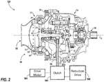
- FIG. 2 schematically illustrates a non-limiting example of an electro-pneumatic starter 120 that may be used to initiate the rotation of a gas turbine engine 250 (see FIG. 1 ), such as a turbofan engine through an accessory gearbox 70, as described above.
- the electro-pneumatic starter 120 may serve as a primary or secondary means of motoring the gas turbine engine 250.
- the electro-pneumatic starter 120 generally includes a housing assembly 30 that includes at least a turbine section 32 and an output section 34.
- the turbine section 32 includes a turbine wheel 36 with a plurality of turbine blades 38, a hub 40, and a turbine rotor shaft 42.
- the turbine blades 38 of the turbine wheel 36 are located downstream of an inlet housing assembly 44 which includes an inlet housing 46 which contains a nozzle 48.
- the nozzle 48 includes a plurality of stator vanes 50 which direct compressed air flow from an inlet 52 through an inlet flow path 54. The compressed air flows past the vanes 50 drives the turbine wheel 36 then is exhausted through an outlet 56.
- the turbine wheel 36 is driven by the compressed airflow such that the turbine rotor shaft 42 may mechanically drive a starter output shaft 58 though a gear system 60, such as a planetary gear system.
- the electro-pneumatic starter 120 thereby transmits relatively high loads through the gear system 60 to convert the pneumatic energy from the compressed air into mechanical energy to, for example, rotate the gas turbine engine 250 for start.
- the turbine blades 38 of the turbine wheel 36 and the vanes 50 of the nozzle 48 - both of which are defined herein as airfoils - may be defined with computational fluid dynamics (CFD) analytical software and are optimized to meet the specific performance requirements of a specific electro-pneumatic starter.
- CFD computational fluid dynamics
- the electro-pneumatic starter 120 is operably connected to the electric drive motor 500.
- the electric drive motor 500 may operably connect to the turbine wheel 36 through a mechanical connection 570.
- the mechanical connection may be a starter cluster gear system 570.
- the drive motor 500 is configured to rotate the electro-pneumatic starter cluster gear system 570, which transfers rotation to the gear box 70 and then to rotational components 260 of the gas turbine engine 250.
- the drive motor 500 may further include a clutch 580 and a reduction drive 590 to operably connect to the turbine wheel 36.
- the clutch 580 may selectively engage and disengage the electric drive motor 500 from the cluster gear system 570.
- the reduction drive 590 may serve as a gear reduction mechanism reducing the output speed of the electric drive motor 500 to the speed required drive the cluster gear system 570.
- FIG. 3 shows a flow diagram illustrating a method 600 of assembling an engine starting system 100 for a gas turbine engine 250, according to an embodiment of the present disclosure.
- a gas turbine engine 250 is obtained.
- the gas turbine engine 250 may include rotational components 260 comprising an engine compressor 256, an engine turbine 258, and a rotor shaft 259 operably connecting the engine turbine 258 to the engine compressor 256.
- Each rotational component 260 is configured to rotate when any one of the rotational components 260 is rotated.
- an electro-pneumatic starter 120 is operably connected to at least one of the rotational components 260.
- the electro-pneumatic starter 120 may comprise a turbine wheel 36 including a hub 40 integrally attached to a turbine rotor shaft 42 and a plurality of turbine blades 38 extending radially from the hub 40.
- the turbine rotor shaft 42 is configured to rotate the rotational components 260 when air flows through the turbine blades 38 and rotates the turbine wheel 36.
- the method 600 may further include: fluidly connecting an auxiliary power unit 310 to the electro-pneumatic starter 120.
- the auxiliary power unit 114 is configured to provide air to the electro-pneumatic starter 120 to rotate the turbine blades 38.
- the method 600 may also further include: electrically connecting the electric drive motor 500 to the auxiliary power unit 114.
- the auxiliary power unit 114 is configured to generate electricity to power the electric drive motor 500.
- a motor controller 320 controls operation of the electric drive motor 500.
- the motor controller 320 being configured to command the electric drive motor 500 to rotate the rotational components 260 at a selected angular velocity for a selected period of time.
- the rotation of the rotational components 260 at selected angular velocity for a selected period of time is engine cool-down motoring, or continuous low speed motoring to prevent bowing of the rotating components.
- the method 700 may also include: detecting when a temperature of the gas turbine engine 250 is less than a selected temperature; and displaying a message on a cockpit display when the temperature of the gas turbine engine 250 is less than a selected temperature.
- the message may indicate that the gas turbine engine 250 has sufficiently cooled.
- the method 700 may further include stopping the utilization of the electric drive motor 500 to rotate the gas turbine engine 250 when a temperature of the gas turbine engine 250 is less than a selected temperature.
- the cool-down motoring may be complete and the electric drive motor 500 may no longer be needed to rotate the rotation components 260 of the gas turbine engine 250.
- the clutch 580 may disengage the electric drive motor 500 when no longer needed.
- the pilot may desire to start the gas turbine engine 250, and thus the method 700 may also include: opening the starter air valve 116 after the message has been displayed on the cockpit display 430 indicating that a temperature of the gas turbine engine 250 is less than a selected temperature. Once the air valve 116 is opened, the method 700 may further include: rotating, using the electro-pneumatic starter 120, rotational components 260 of the gas turbine engine 250 when the starter air valve 116 is opened.
- embodiments can be in the form of processor-implemented processes and devices for practicing those processes, such as a processor.
- Embodiments can also be in the form of computer program code containing instructions embodied in tangible media, such as floppy diskettes, CD ROMs, hard drives, or any other computer-readable storage medium, wherein, when the computer program code is loaded into and executed by a computer, the computer becomes a device for practicing the embodiments.
- Embodiments can also be in the form of computer program code, for example, whether stored in a storage medium, loaded into and/or executed by a computer, or transmitted over some transmission medium, loaded into and/or executed by a computer, or transmitted over some transmission medium, such as over electrical wiring or cabling, through fibre optics, or via electromagnetic radiation, wherein, when the computer program code is loaded into an executed by a computer, the computer becomes an device for practicing the exemplary embodiments.
- the computer program code segments configure the microprocessor to create specific logic circuits.
Landscapes
- Engineering & Computer Science (AREA)
- Chemical & Material Sciences (AREA)
- Combustion & Propulsion (AREA)
- Mechanical Engineering (AREA)
- General Engineering & Computer Science (AREA)
- Supercharger (AREA)
Priority Applications (1)
| Application Number | Priority Date | Filing Date | Title |
|---|---|---|---|
| EP21170238.6A EP3872327B1 (de) | 2016-02-12 | 2017-02-13 | Elektropneumatisches gasturbinentriebwerkmotorisierungssystem zum anlassen von motoren mit gebogenem rotor |
Applications Claiming Priority (1)
| Application Number | Priority Date | Filing Date | Title |
|---|---|---|---|
| US201662294554P | 2016-02-12 | 2016-02-12 |
Related Child Applications (1)
| Application Number | Title | Priority Date | Filing Date |
|---|---|---|---|
| EP21170238.6A Division EP3872327B1 (de) | 2016-02-12 | 2017-02-13 | Elektropneumatisches gasturbinentriebwerkmotorisierungssystem zum anlassen von motoren mit gebogenem rotor |
Publications (2)
| Publication Number | Publication Date |
|---|---|
| EP3205860A1 true EP3205860A1 (de) | 2017-08-16 |
| EP3205860B1 EP3205860B1 (de) | 2021-05-26 |
Family
ID=58054009
Family Applications (2)
| Application Number | Title | Priority Date | Filing Date |
|---|---|---|---|
| EP17155902.4A Active EP3205860B1 (de) | 2016-02-12 | 2017-02-13 | Elektropneumatisches gasturbinenmotormotorisierungssystem für starts von motoren mit gebogenem rotor |
| EP21170238.6A Active EP3872327B1 (de) | 2016-02-12 | 2017-02-13 | Elektropneumatisches gasturbinentriebwerkmotorisierungssystem zum anlassen von motoren mit gebogenem rotor |
Family Applications After (1)
| Application Number | Title | Priority Date | Filing Date |
|---|---|---|---|
| EP21170238.6A Active EP3872327B1 (de) | 2016-02-12 | 2017-02-13 | Elektropneumatisches gasturbinentriebwerkmotorisierungssystem zum anlassen von motoren mit gebogenem rotor |
Country Status (2)
| Country | Link |
|---|---|
| US (2) | US20170234235A1 (de) |
| EP (2) | EP3205860B1 (de) |
Cited By (1)
| Publication number | Priority date | Publication date | Assignee | Title |
|---|---|---|---|---|
| EP3279449A1 (de) * | 2016-08-01 | 2018-02-07 | Honeywell International Inc. | Luftturbinenstarter mit integriertem motor für hauptmotorkühlung |
Families Citing this family (38)
| Publication number | Priority date | Publication date | Assignee | Title |
|---|---|---|---|---|
| US10125636B2 (en) | 2016-02-12 | 2018-11-13 | United Technologies Corporation | Bowed rotor prevention system using waste heat |
| US10508567B2 (en) | 2016-02-12 | 2019-12-17 | United Technologies Corporation | Auxiliary drive bowed rotor prevention system for a gas turbine engine through an engine accessory |
| US10539079B2 (en) | 2016-02-12 | 2020-01-21 | United Technologies Corporation | Bowed rotor start mitigation in a gas turbine engine using aircraft-derived parameters |
| US10040577B2 (en) * | 2016-02-12 | 2018-08-07 | United Technologies Corporation | Modified start sequence of a gas turbine engine |
| US10436064B2 (en) | 2016-02-12 | 2019-10-08 | United Technologies Corporation | Bowed rotor start response damping system |
| US10174678B2 (en) | 2016-02-12 | 2019-01-08 | United Technologies Corporation | Bowed rotor start using direct temperature measurement |
| US20170234234A1 (en) * | 2016-02-12 | 2017-08-17 | Hamilton Sundstrand Corporation | Gas turbine engine motoring system for bowed rotor engine starts |
| US10508601B2 (en) | 2016-02-12 | 2019-12-17 | United Technologies Corporation | Auxiliary drive bowed rotor prevention system for a gas turbine engine |
| US10443507B2 (en) | 2016-02-12 | 2019-10-15 | United Technologies Corporation | Gas turbine engine bowed rotor avoidance system |
| US10125691B2 (en) | 2016-02-12 | 2018-11-13 | United Technologies Corporation | Bowed rotor start using a variable position starter valve |
| US9664070B1 (en) | 2016-02-12 | 2017-05-30 | United Technologies Corporation | Bowed rotor prevention system |
| US10443505B2 (en) | 2016-02-12 | 2019-10-15 | United Technologies Corporation | Bowed rotor start mitigation in a gas turbine engine |
| US10598047B2 (en) | 2016-02-29 | 2020-03-24 | United Technologies Corporation | Low-power bowed rotor prevention system |
| US10731501B2 (en) * | 2016-04-22 | 2020-08-04 | Hamilton Sundstrand Corporation | Environmental control system utilizing a motor assist and an enhanced compressor |
| US10787933B2 (en) * | 2016-06-20 | 2020-09-29 | Raytheon Technologies Corporation | Low-power bowed rotor prevention and monitoring system |
| US10358936B2 (en) | 2016-07-05 | 2019-07-23 | United Technologies Corporation | Bowed rotor sensor system |
| EP3273006B1 (de) | 2016-07-21 | 2019-07-03 | United Technologies Corporation | Verwendung eines alternierenden anlassers während des anfahrens mit mehreren motoren |
| US10618666B2 (en) | 2016-07-21 | 2020-04-14 | United Technologies Corporation | Pre-start motoring synchronization for multiple engines |
| US10384791B2 (en) * | 2016-07-21 | 2019-08-20 | United Technologies Corporation | Cross engine coordination during gas turbine engine motoring |
| EP3273016B1 (de) | 2016-07-21 | 2020-04-01 | United Technologies Corporation | Koordination während des anlassens eines gasturbinenmotors |
| JP6687485B2 (ja) * | 2016-08-31 | 2020-04-22 | 三菱日立パワーシステムズ株式会社 | 二軸ガスタービン発電設備 |
| US10787968B2 (en) | 2016-09-30 | 2020-09-29 | Raytheon Technologies Corporation | Gas turbine engine motoring with starter air valve manual override |
| US10823079B2 (en) | 2016-11-29 | 2020-11-03 | Raytheon Technologies Corporation | Metered orifice for motoring of a gas turbine engine |
| US10753225B2 (en) * | 2017-03-31 | 2020-08-25 | The Boeing Company | Engine turning motor via pneumatic or hydraulic motor |
| US10718231B2 (en) * | 2017-12-15 | 2020-07-21 | General Electric Company | Method and system for mitigating bowed rotor operation of gas turbine engine |
| US10634057B2 (en) | 2018-01-19 | 2020-04-28 | Hamilton Sundstrand Corporation | Airflow control for air turbine starter |
| US11162419B2 (en) * | 2018-02-12 | 2021-11-02 | General Electric Company | Method and structure for operating engine with bowed rotor condition |
| US11261795B2 (en) | 2018-10-18 | 2022-03-01 | Rolls-Royce North American Technologies, Inc. | Dual mode starter generator |
| CA3053117A1 (en) * | 2018-10-18 | 2020-04-18 | Rolls-Royce North American Technologies Inc. | Dual mode starter generator |
| US11015532B2 (en) | 2018-10-18 | 2021-05-25 | Rolls-Royce North American Technologies, Inc. | Parallel starter/generator and air turbine starter |
| US11486310B2 (en) | 2020-03-27 | 2022-11-01 | Pratt & Whitney Canada Corp. | System and method for dynamic engine motoring |
| US11668248B2 (en) | 2020-03-27 | 2023-06-06 | Pratt & Whitney Canada Corp. | Start-up system and method for rotor bow mitigation |
| US11933232B1 (en) * | 2023-02-21 | 2024-03-19 | General Electric Company | Hybrid-electric gas turbine engine and method of operating |
| US12146443B2 (en) * | 2023-03-31 | 2024-11-19 | Pratt & Whitney Canada Corp. | Boosting gas turbine engine power with fluid motor |
| US12366208B2 (en) | 2023-07-28 | 2025-07-22 | Unison Industries, Llc | Turbine engine including an engine starter assembly |
| US12313006B1 (en) * | 2023-11-29 | 2025-05-27 | Unison Industries, Llc | Turbine engine including an air turbine starter |
| CN118188170B (zh) * | 2024-01-26 | 2024-11-12 | 中国航发湖南动力机械研究所 | 航空涡轴发动机及极寒环境下的起动方法 |
| US12546260B2 (en) * | 2024-05-09 | 2026-02-10 | Hamilton Sundstrand Corporation | Pneumatic start system with integrated electric generator powered by engine environmental control bleed supply |
Citations (3)
| Publication number | Priority date | Publication date | Assignee | Title |
|---|---|---|---|---|
| EP2554799A2 (de) * | 2011-08-01 | 2013-02-06 | Hamilton Sundstrand Corporation | Gasturbinenstartarchitektur und Verfahren zum Starten einer solchen Turbine |
| US20140123673A1 (en) * | 2011-07-12 | 2014-05-08 | Turbomeca | A method of starting a turbomachine while reducing thermal unbalance |
| US20140373553A1 (en) * | 2013-06-25 | 2014-12-25 | Airbus Operations (Sas) | Method and system for starting up an aircraft turbomachine |
Family Cites Families (9)
| Publication number | Priority date | Publication date | Assignee | Title |
|---|---|---|---|---|
| US4473752A (en) * | 1982-05-27 | 1984-09-25 | Lockheed Corporation | Aircraft engine starting with synchronous ac generator |
| US20080296909A1 (en) * | 2007-05-29 | 2008-12-04 | Smiths Aerospace Llc | Turbo-Pneumatic Assist for Electric Motor Starting |
| US8370045B2 (en) * | 2009-08-14 | 2013-02-05 | Lockheed Martin Corporation | Starter control valve failure prediction machine to predict and trend starter control valve failures in gas turbine engines using a starter control valve health prognostic, program product and related methods |
| FR2972485B1 (fr) * | 2011-03-08 | 2013-04-12 | Snecma | Procede de surveillance du changement d'etat d'une vanne par mesure de pression. |
| US20130076035A1 (en) * | 2011-09-27 | 2013-03-28 | Andreas C. Koenig | Motor-generator turbomachine starter |
| US10309317B2 (en) * | 2013-06-21 | 2019-06-04 | Hamilton Sundstrand Corporation | Air turbine starter pressure monitor system |
| US20170234237A1 (en) * | 2016-02-12 | 2017-08-17 | Hamilton Sundstrand Corporation | Gas turbine engine motoring variable frequency generator system for bowed rotor engine starts |
| US20180030900A1 (en) * | 2016-08-01 | 2018-02-01 | Honeywell International Inc. | Air Turbine Starter with Integrated Motor for Main Engine Cooling |
| US10823079B2 (en) * | 2016-11-29 | 2020-11-03 | Raytheon Technologies Corporation | Metered orifice for motoring of a gas turbine engine |
-
2017
- 2017-02-10 US US15/429,808 patent/US20170234235A1/en not_active Abandoned
- 2017-02-13 EP EP17155902.4A patent/EP3205860B1/de active Active
- 2017-02-13 EP EP21170238.6A patent/EP3872327B1/de active Active
-
2019
- 2019-03-27 US US16/365,977 patent/US20190218975A1/en not_active Abandoned
Patent Citations (3)
| Publication number | Priority date | Publication date | Assignee | Title |
|---|---|---|---|---|
| US20140123673A1 (en) * | 2011-07-12 | 2014-05-08 | Turbomeca | A method of starting a turbomachine while reducing thermal unbalance |
| EP2554799A2 (de) * | 2011-08-01 | 2013-02-06 | Hamilton Sundstrand Corporation | Gasturbinenstartarchitektur und Verfahren zum Starten einer solchen Turbine |
| US20140373553A1 (en) * | 2013-06-25 | 2014-12-25 | Airbus Operations (Sas) | Method and system for starting up an aircraft turbomachine |
Cited By (1)
| Publication number | Priority date | Publication date | Assignee | Title |
|---|---|---|---|---|
| EP3279449A1 (de) * | 2016-08-01 | 2018-02-07 | Honeywell International Inc. | Luftturbinenstarter mit integriertem motor für hauptmotorkühlung |
Also Published As
| Publication number | Publication date |
|---|---|
| US20170234235A1 (en) | 2017-08-17 |
| EP3205860B1 (de) | 2021-05-26 |
| EP3872327B1 (de) | 2023-06-14 |
| EP3872327A1 (de) | 2021-09-01 |
| US20190218975A1 (en) | 2019-07-18 |
Similar Documents
| Publication | Publication Date | Title |
|---|---|---|
| EP3205860B1 (de) | Elektropneumatisches gasturbinenmotormotorisierungssystem für starts von motoren mit gebogenem rotor | |
| EP3205838B1 (de) | Gasturbinen antriebssystem für triebwerkstarts bei durchbogenem rotor | |
| EP3205850B1 (de) | Frequenzvariables gasturbinenmotormotorisierungsgeneratorsystem für starts von motoren mit gebogenem rotor | |
| CN110114567B (zh) | 用于启动燃气涡轮发动机的系统和方法 | |
| US20220154600A1 (en) | Pneumatic starter supplemental lubrication system | |
| EP3464834B1 (de) | Turbinenmotor und betriebsverfahren | |
| US9878796B2 (en) | Hybrid drive for gas turbine engine | |
| US9328667B2 (en) | Systems and methods for changing a speed of a compressor boost stage in a gas turbine | |
| CN109110135B (zh) | 用于飞行器的推进系统 | |
| US20180016933A1 (en) | Method and system for soak-back mitigation by active cooling | |
| EP3406864B1 (de) | Bogenläufersteuerung | |
| JP2019023068A (ja) | 航空機用推進システム | |
| CN109958484B (zh) | 缓解涡轮发动机中的转子弯曲的结构和方法 | |
| EP3376005B1 (de) | Luftturbinenstarter mit automatisierten variablen einlassschaufeln | |
| US10711701B2 (en) | Manual bowed rotor and full override | |
| US8800295B2 (en) | Device and a method for regulating a turbine engine, and an aircraft | |
| EP2924247B1 (de) | Hybridantrieb für gasturbinenmotor |
Legal Events
| Date | Code | Title | Description |
|---|---|---|---|
| PUAI | Public reference made under article 153(3) epc to a published international application that has entered the european phase |
Free format text: ORIGINAL CODE: 0009012 |
|
| STAA | Information on the status of an ep patent application or granted ep patent |
Free format text: STATUS: THE APPLICATION HAS BEEN PUBLISHED |
|
| AK | Designated contracting states |
Kind code of ref document: A1 Designated state(s): AL AT BE BG CH CY CZ DE DK EE ES FI FR GB GR HR HU IE IS IT LI LT LU LV MC MK MT NL NO PL PT RO RS SE SI SK SM TR |
|
| AX | Request for extension of the european patent |
Extension state: BA ME |
|
| STAA | Information on the status of an ep patent application or granted ep patent |
Free format text: STATUS: REQUEST FOR EXAMINATION WAS MADE |
|
| 17P | Request for examination filed |
Effective date: 20180213 |
|
| RBV | Designated contracting states (corrected) |
Designated state(s): AL AT BE BG CH CY CZ DE DK EE ES FI FR GB GR HR HU IE IS IT LI LT LU LV MC MK MT NL NO PL PT RO RS SE SI SK SM TR |
|
| STAA | Information on the status of an ep patent application or granted ep patent |
Free format text: STATUS: EXAMINATION IS IN PROGRESS |
|
| 17Q | First examination report despatched |
Effective date: 20181009 |
|
| GRAP | Despatch of communication of intention to grant a patent |
Free format text: ORIGINAL CODE: EPIDOSNIGR1 |
|
| STAA | Information on the status of an ep patent application or granted ep patent |
Free format text: STATUS: GRANT OF PATENT IS INTENDED |
|
| RIC1 | Information provided on ipc code assigned before grant |
Ipc: F02C 7/277 20060101AFI20201130BHEP Ipc: F02C 7/36 20060101ALI20201130BHEP |
|
| INTG | Intention to grant announced |
Effective date: 20201222 |
|
| GRAS | Grant fee paid |
Free format text: ORIGINAL CODE: EPIDOSNIGR3 |
|
| GRAA | (expected) grant |
Free format text: ORIGINAL CODE: 0009210 |
|
| STAA | Information on the status of an ep patent application or granted ep patent |
Free format text: STATUS: THE PATENT HAS BEEN GRANTED |
|
| AK | Designated contracting states |
Kind code of ref document: B1 Designated state(s): AL AT BE BG CH CY CZ DE DK EE ES FI FR GB GR HR HU IE IS IT LI LT LU LV MC MK MT NL NO PL PT RO RS SE SI SK SM TR |
|
| REG | Reference to a national code |
Ref country code: GB Ref legal event code: FG4D |
|
| REG | Reference to a national code |
Ref country code: CH Ref legal event code: EP |
|
| REG | Reference to a national code |
Ref country code: AT Ref legal event code: REF Ref document number: 1396441 Country of ref document: AT Kind code of ref document: T Effective date: 20210615 |
|
| REG | Reference to a national code |
Ref country code: DE Ref legal event code: R096 Ref document number: 602017039094 Country of ref document: DE |
|
| REG | Reference to a national code |
Ref country code: IE Ref legal event code: FG4D |
|
| REG | Reference to a national code |
Ref country code: LT Ref legal event code: MG9D |
|
| REG | Reference to a national code |
Ref country code: AT Ref legal event code: MK05 Ref document number: 1396441 Country of ref document: AT Kind code of ref document: T Effective date: 20210526 |
|
| PG25 | Lapsed in a contracting state [announced via postgrant information from national office to epo] |
Ref country code: HR Free format text: LAPSE BECAUSE OF FAILURE TO SUBMIT A TRANSLATION OF THE DESCRIPTION OR TO PAY THE FEE WITHIN THE PRESCRIBED TIME-LIMIT Effective date: 20210526 Ref country code: AT Free format text: LAPSE BECAUSE OF FAILURE TO SUBMIT A TRANSLATION OF THE DESCRIPTION OR TO PAY THE FEE WITHIN THE PRESCRIBED TIME-LIMIT Effective date: 20210526 Ref country code: BG Free format text: LAPSE BECAUSE OF FAILURE TO SUBMIT A TRANSLATION OF THE DESCRIPTION OR TO PAY THE FEE WITHIN THE PRESCRIBED TIME-LIMIT Effective date: 20210826 Ref country code: FI Free format text: LAPSE BECAUSE OF FAILURE TO SUBMIT A TRANSLATION OF THE DESCRIPTION OR TO PAY THE FEE WITHIN THE PRESCRIBED TIME-LIMIT Effective date: 20210526 Ref country code: LT Free format text: LAPSE BECAUSE OF FAILURE TO SUBMIT A TRANSLATION OF THE DESCRIPTION OR TO PAY THE FEE WITHIN THE PRESCRIBED TIME-LIMIT Effective date: 20210526 |
|
| REG | Reference to a national code |
Ref country code: NL Ref legal event code: MP Effective date: 20210526 |
|
| PG25 | Lapsed in a contracting state [announced via postgrant information from national office to epo] |
Ref country code: SE Free format text: LAPSE BECAUSE OF FAILURE TO SUBMIT A TRANSLATION OF THE DESCRIPTION OR TO PAY THE FEE WITHIN THE PRESCRIBED TIME-LIMIT Effective date: 20210526 Ref country code: RS Free format text: LAPSE BECAUSE OF FAILURE TO SUBMIT A TRANSLATION OF THE DESCRIPTION OR TO PAY THE FEE WITHIN THE PRESCRIBED TIME-LIMIT Effective date: 20210526 Ref country code: PT Free format text: LAPSE BECAUSE OF FAILURE TO SUBMIT A TRANSLATION OF THE DESCRIPTION OR TO PAY THE FEE WITHIN THE PRESCRIBED TIME-LIMIT Effective date: 20210927 Ref country code: NO Free format text: LAPSE BECAUSE OF FAILURE TO SUBMIT A TRANSLATION OF THE DESCRIPTION OR TO PAY THE FEE WITHIN THE PRESCRIBED TIME-LIMIT Effective date: 20210826 Ref country code: PL Free format text: LAPSE BECAUSE OF FAILURE TO SUBMIT A TRANSLATION OF THE DESCRIPTION OR TO PAY THE FEE WITHIN THE PRESCRIBED TIME-LIMIT Effective date: 20210526 Ref country code: LV Free format text: LAPSE BECAUSE OF FAILURE TO SUBMIT A TRANSLATION OF THE DESCRIPTION OR TO PAY THE FEE WITHIN THE PRESCRIBED TIME-LIMIT Effective date: 20210526 Ref country code: IS Free format text: LAPSE BECAUSE OF FAILURE TO SUBMIT A TRANSLATION OF THE DESCRIPTION OR TO PAY THE FEE WITHIN THE PRESCRIBED TIME-LIMIT Effective date: 20210926 Ref country code: GR Free format text: LAPSE BECAUSE OF FAILURE TO SUBMIT A TRANSLATION OF THE DESCRIPTION OR TO PAY THE FEE WITHIN THE PRESCRIBED TIME-LIMIT Effective date: 20210827 |
|
| PG25 | Lapsed in a contracting state [announced via postgrant information from national office to epo] |
Ref country code: NL Free format text: LAPSE BECAUSE OF FAILURE TO SUBMIT A TRANSLATION OF THE DESCRIPTION OR TO PAY THE FEE WITHIN THE PRESCRIBED TIME-LIMIT Effective date: 20210526 |
|
| PG25 | Lapsed in a contracting state [announced via postgrant information from national office to epo] |
Ref country code: SK Free format text: LAPSE BECAUSE OF FAILURE TO SUBMIT A TRANSLATION OF THE DESCRIPTION OR TO PAY THE FEE WITHIN THE PRESCRIBED TIME-LIMIT Effective date: 20210526 Ref country code: SM Free format text: LAPSE BECAUSE OF FAILURE TO SUBMIT A TRANSLATION OF THE DESCRIPTION OR TO PAY THE FEE WITHIN THE PRESCRIBED TIME-LIMIT Effective date: 20210526 Ref country code: CZ Free format text: LAPSE BECAUSE OF FAILURE TO SUBMIT A TRANSLATION OF THE DESCRIPTION OR TO PAY THE FEE WITHIN THE PRESCRIBED TIME-LIMIT Effective date: 20210526 Ref country code: DK Free format text: LAPSE BECAUSE OF FAILURE TO SUBMIT A TRANSLATION OF THE DESCRIPTION OR TO PAY THE FEE WITHIN THE PRESCRIBED TIME-LIMIT Effective date: 20210526 Ref country code: EE Free format text: LAPSE BECAUSE OF FAILURE TO SUBMIT A TRANSLATION OF THE DESCRIPTION OR TO PAY THE FEE WITHIN THE PRESCRIBED TIME-LIMIT Effective date: 20210526 Ref country code: RO Free format text: LAPSE BECAUSE OF FAILURE TO SUBMIT A TRANSLATION OF THE DESCRIPTION OR TO PAY THE FEE WITHIN THE PRESCRIBED TIME-LIMIT Effective date: 20210526 Ref country code: ES Free format text: LAPSE BECAUSE OF FAILURE TO SUBMIT A TRANSLATION OF THE DESCRIPTION OR TO PAY THE FEE WITHIN THE PRESCRIBED TIME-LIMIT Effective date: 20210526 |
|
| REG | Reference to a national code |
Ref country code: DE Ref legal event code: R097 Ref document number: 602017039094 Country of ref document: DE |
|
| PLBE | No opposition filed within time limit |
Free format text: ORIGINAL CODE: 0009261 |
|
| STAA | Information on the status of an ep patent application or granted ep patent |
Free format text: STATUS: NO OPPOSITION FILED WITHIN TIME LIMIT |
|
| 26N | No opposition filed |
Effective date: 20220301 |
|
| PG25 | Lapsed in a contracting state [announced via postgrant information from national office to epo] |
Ref country code: IS Free format text: LAPSE BECAUSE OF FAILURE TO SUBMIT A TRANSLATION OF THE DESCRIPTION OR TO PAY THE FEE WITHIN THE PRESCRIBED TIME-LIMIT Effective date: 20210926 Ref country code: AL Free format text: LAPSE BECAUSE OF FAILURE TO SUBMIT A TRANSLATION OF THE DESCRIPTION OR TO PAY THE FEE WITHIN THE PRESCRIBED TIME-LIMIT Effective date: 20210526 |
|
| PG25 | Lapsed in a contracting state [announced via postgrant information from national office to epo] |
Ref country code: IT Free format text: LAPSE BECAUSE OF FAILURE TO SUBMIT A TRANSLATION OF THE DESCRIPTION OR TO PAY THE FEE WITHIN THE PRESCRIBED TIME-LIMIT Effective date: 20210526 |
|
| PG25 | Lapsed in a contracting state [announced via postgrant information from national office to epo] |
Ref country code: MC Free format text: LAPSE BECAUSE OF FAILURE TO SUBMIT A TRANSLATION OF THE DESCRIPTION OR TO PAY THE FEE WITHIN THE PRESCRIBED TIME-LIMIT Effective date: 20210526 |
|
| REG | Reference to a national code |
Ref country code: CH Ref legal event code: PL |
|
| REG | Reference to a national code |
Ref country code: BE Ref legal event code: MM Effective date: 20220228 |
|
| PG25 | Lapsed in a contracting state [announced via postgrant information from national office to epo] |
Ref country code: LU Free format text: LAPSE BECAUSE OF NON-PAYMENT OF DUE FEES Effective date: 20220213 |
|
| PG25 | Lapsed in a contracting state [announced via postgrant information from national office to epo] |
Ref country code: LI Free format text: LAPSE BECAUSE OF NON-PAYMENT OF DUE FEES Effective date: 20220228 Ref country code: IE Free format text: LAPSE BECAUSE OF NON-PAYMENT OF DUE FEES Effective date: 20220213 Ref country code: CH Free format text: LAPSE BECAUSE OF NON-PAYMENT OF DUE FEES Effective date: 20220228 |
|
| PG25 | Lapsed in a contracting state [announced via postgrant information from national office to epo] |
Ref country code: BE Free format text: LAPSE BECAUSE OF NON-PAYMENT OF DUE FEES Effective date: 20220228 |
|
| P01 | Opt-out of the competence of the unified patent court (upc) registered |
Effective date: 20230522 |
|
| PG25 | Lapsed in a contracting state [announced via postgrant information from national office to epo] |
Ref country code: HU Free format text: LAPSE BECAUSE OF FAILURE TO SUBMIT A TRANSLATION OF THE DESCRIPTION OR TO PAY THE FEE WITHIN THE PRESCRIBED TIME-LIMIT; INVALID AB INITIO Effective date: 20170213 |
|
| PG25 | Lapsed in a contracting state [announced via postgrant information from national office to epo] |
Ref country code: MK Free format text: LAPSE BECAUSE OF FAILURE TO SUBMIT A TRANSLATION OF THE DESCRIPTION OR TO PAY THE FEE WITHIN THE PRESCRIBED TIME-LIMIT Effective date: 20210526 Ref country code: CY Free format text: LAPSE BECAUSE OF FAILURE TO SUBMIT A TRANSLATION OF THE DESCRIPTION OR TO PAY THE FEE WITHIN THE PRESCRIBED TIME-LIMIT Effective date: 20210526 |
|
| PG25 | Lapsed in a contracting state [announced via postgrant information from national office to epo] |
Ref country code: MT Free format text: LAPSE BECAUSE OF FAILURE TO SUBMIT A TRANSLATION OF THE DESCRIPTION OR TO PAY THE FEE WITHIN THE PRESCRIBED TIME-LIMIT Effective date: 20210526 |
|
| PG25 | Lapsed in a contracting state [announced via postgrant information from national office to epo] |
Ref country code: TR Free format text: LAPSE BECAUSE OF FAILURE TO SUBMIT A TRANSLATION OF THE DESCRIPTION OR TO PAY THE FEE WITHIN THE PRESCRIBED TIME-LIMIT Effective date: 20210526 |
|
| PGFP | Annual fee paid to national office [announced via postgrant information from national office to epo] |
Ref country code: GB Payment date: 20260122 Year of fee payment: 10 |
|
| PGFP | Annual fee paid to national office [announced via postgrant information from national office to epo] |
Ref country code: DE Payment date: 20260121 Year of fee payment: 10 |
|
| PGFP | Annual fee paid to national office [announced via postgrant information from national office to epo] |
Ref country code: FR Payment date: 20260121 Year of fee payment: 10 |