EP3205879B1 - Dispositif de gonflage - Google Patents
Dispositif de gonflage Download PDFInfo
- Publication number
- EP3205879B1 EP3205879B1 EP14903584.2A EP14903584A EP3205879B1 EP 3205879 B1 EP3205879 B1 EP 3205879B1 EP 14903584 A EP14903584 A EP 14903584A EP 3205879 B1 EP3205879 B1 EP 3205879B1
- Authority
- EP
- European Patent Office
- Prior art keywords
- gas
- intake valve
- exhaust valve
- gas exhaust
- gas intake
- Prior art date
- Legal status (The legal status is an assumption and is not a legal conclusion. Google has not performed a legal analysis and makes no representation as to the accuracy of the status listed.)
- Active
Links
Images


Classifications
-
- F—MECHANICAL ENGINEERING; LIGHTING; HEATING; WEAPONS; BLASTING
- F04—POSITIVE - DISPLACEMENT MACHINES FOR LIQUIDS; PUMPS FOR LIQUIDS OR ELASTIC FLUIDS
- F04B—POSITIVE-DISPLACEMENT MACHINES FOR LIQUIDS; PUMPS
- F04B33/00—Pumps actuated by muscle power, e.g. for inflating
-
- F—MECHANICAL ENGINEERING; LIGHTING; HEATING; WEAPONS; BLASTING
- F04—POSITIVE - DISPLACEMENT MACHINES FOR LIQUIDS; PUMPS FOR LIQUIDS OR ELASTIC FLUIDS
- F04B—POSITIVE-DISPLACEMENT MACHINES FOR LIQUIDS; PUMPS
- F04B39/00—Component parts, details, or accessories, of pumps or pumping systems specially adapted for elastic fluids, not otherwise provided for in, or of interest apart from, groups F04B25/00 - F04B37/00
- F04B39/10—Adaptations or arrangements of distribution members
-
- F—MECHANICAL ENGINEERING; LIGHTING; HEATING; WEAPONS; BLASTING
- F04—POSITIVE - DISPLACEMENT MACHINES FOR LIQUIDS; PUMPS FOR LIQUIDS OR ELASTIC FLUIDS
- F04B—POSITIVE-DISPLACEMENT MACHINES FOR LIQUIDS; PUMPS
- F04B39/00—Component parts, details, or accessories, of pumps or pumping systems specially adapted for elastic fluids, not otherwise provided for in, or of interest apart from, groups F04B25/00 - F04B37/00
- F04B39/10—Adaptations or arrangements of distribution members
- F04B39/1013—Adaptations or arrangements of distribution members the members being of the poppet valve type
-
- F—MECHANICAL ENGINEERING; LIGHTING; HEATING; WEAPONS; BLASTING
- F04—POSITIVE - DISPLACEMENT MACHINES FOR LIQUIDS; PUMPS FOR LIQUIDS OR ELASTIC FLUIDS
- F04B—POSITIVE-DISPLACEMENT MACHINES FOR LIQUIDS; PUMPS
- F04B45/00—Pumps or pumping installations having flexible working members and specially adapted for elastic fluids
-
- F—MECHANICAL ENGINEERING; LIGHTING; HEATING; WEAPONS; BLASTING
- F04—POSITIVE - DISPLACEMENT MACHINES FOR LIQUIDS; PUMPS FOR LIQUIDS OR ELASTIC FLUIDS
- F04B—POSITIVE-DISPLACEMENT MACHINES FOR LIQUIDS; PUMPS
- F04B45/00—Pumps or pumping installations having flexible working members and specially adapted for elastic fluids
- F04B45/02—Pumps or pumping installations having flexible working members and specially adapted for elastic fluids having bellows
-
- F—MECHANICAL ENGINEERING; LIGHTING; HEATING; WEAPONS; BLASTING
- F04—POSITIVE - DISPLACEMENT MACHINES FOR LIQUIDS; PUMPS FOR LIQUIDS OR ELASTIC FLUIDS
- F04B—POSITIVE-DISPLACEMENT MACHINES FOR LIQUIDS; PUMPS
- F04B45/00—Pumps or pumping installations having flexible working members and specially adapted for elastic fluids
- F04B45/04—Pumps or pumping installations having flexible working members and specially adapted for elastic fluids having plate-like flexible members, e.g. diaphragms
-
- F—MECHANICAL ENGINEERING; LIGHTING; HEATING; WEAPONS; BLASTING
- F04—POSITIVE - DISPLACEMENT MACHINES FOR LIQUIDS; PUMPS FOR LIQUIDS OR ELASTIC FLUIDS
- F04B—POSITIVE-DISPLACEMENT MACHINES FOR LIQUIDS; PUMPS
- F04B53/00—Component parts, details or accessories not provided for in, or of interest apart from, groups F04B1/00 - F04B23/00 or F04B39/00 - F04B47/00
- F04B53/10—Valves; Arrangement of valves
- F04B53/102—Disc valves
- F04B53/1022—Disc valves having means for guiding the closure member axially
- F04B53/1025—Disc valves having means for guiding the closure member axially the guiding means being provided within the valve opening
Definitions
- the invention relates to an inflating device, and in particular to a device which is simple in structure and convenient to use and can realize manual inflation without requiring other tools.
- United States Patent Publication No. US 2011/ 0293454 A1 discloses an inflating device according to the preamble of claim 1, the inflating device having an air bladder, a base, a resilient membrane, and two air valves.
- China utility model patent No. CN 201772115 U also discloses inflating valve which includes a valve seating, a valve block, a valve core, a spring, and a bottom cap. But the devices in those patents are inconvenient to use.
- a technical problem required to be solved by the invention is to provide an inflating device, which has a small volume and a simple structure, is convenient to use without requiring any power supply, and allows for a simple deflating operation.
- An inflating device including a valve body and a gasbag, the valve body being provided with a gas inlet, a gas outlet and a gas storage chamber; the gas inlet has a gas intake valve device provided therein, and the gas outlet has a gas exhaust valve device provided therein; the gas storage chamber is communicated with the gasbag; and the gas inlet is communicated with the gas outlet through a chamber body of the valve body, and the gas storage chamber is communicated with the chamber body.
- the gas exhaust valve device includes a gas exhaust valve base having a gas exhaust valve through hole provided therein, and a gas exhaust valve ring is provided in the gas exhaust valve through hole; and the gas exhaust valve ring is connected to a wall of the gas exhaust valve through hole by at least two gas exhaust valve supporting bars, and the gas exhaust valve base, the gas exhaust valve ring and the gas exhaust valve supporting bars are integrated.
- a gas exhaust valve core passes through and is axially moveable in an inner hole of the gas exhaust valve ring; an annular protrusion, which is larger than the inner hole of the gas exhaust valve ring and radially faces outward, is provided on an outer end of the gas exhaust valve core, an inner end of the gas exhaust valve core is connected with a gas exhaust valve raised-bonnet which is larger than the inner hole of the gas exhaust valve ring, and the gas exhaust valve ring is positioned between the annular protrusion and the gas exhaust valve raised-bonnet; a gas exhaust valve spring is provided between the gas exhaust valve raised-bonnet and the gas exhaust valve ring, and the inner end of the gas exhaust valve core passes through the gas exhaust valve spring; and the outer end of the gas exhaust valve core faces outside the valve body, and the inner end of the gas exhaust valve core faces the chamber body of the valve body.
- the outer end of the gas exhaust valve core is connected with a gas exhaust valve seal
- an annular slope is provided at an outer end of the gas exhaust valve through hole
- the shape and size of the annular slope are matched with those of the gas exhaust valve seal
- the gas exhaust valve spring enables the gas exhaust valve seal to seal the gas exhaust valve through hole after coming into close contact with the annular slope.
- an extension portion is provided on an inner side of the gas exhaust valve seal, and the extension portion is an elastomer; one end, far away from the gas exhaust value seal, of the extension portion is a distal end of the extension portion; and the distal end has a bump radially facing outward, the bump is positioned within a slot of the gas exhaust valve core after passing through the inner hole of the gas exhaust valve core, and the bump is larger than the inner hole of the gas exhaust valve core.
- the gas intake valve device includes a gas intake valve base having a gas intake valve through hole provided therein, and a gas intake valve ring is provided in the gas intake valve through hole; and the gas intake valve ring is connected to a wall of the gas intake valve through hole by at least two gas intake valve supporting bars, and the gas intake valve base, the gas intake valve ring and the gas intake valve supporting bars are integrated.
- a gas intake valve core passes through and is axially movable in an inner hole of the gas intake valve ring; an annular protrusion, which is larger than the inner hole of the gas intake valve ring and radially faces outward, is provided on an outer end of the gas intake valve core, an inner end of the gas intake valve core is connected with a gas intake valve raised-bonnet which is larger than the inner hole of the gas intake valve ring, and the gas intake valve ring is positioned between the annular protrusion and the gas intake valve bonnet; a gas intake valve spring is provided between the gas intake valve raised-bonnet and the gas intake valve ring, and the inner end of the gas intake valve core passes through the gas intake valve spring; and the outer end of the gas intake valve core faces the chamber body of the valve body, and the inner end of the gas intake valve core faces outside the valve body.
- the outer end of the gas intake valve core is connected with a gas intake valve seal
- an annular slope is provided at an outer end of the gas intake valve through hole, the shape and size of the annular slope are matched with those of the gas intake valve seal, and the gas intake valve spring enables the gas intake valve seal to seal the gas intake valve through hole after coming into close contact with the annular slope; and the outer end of the gas intake valve through hole faces the chamber body of the valve body, and the inner end of the gas intake valve through hole faces outside the valve body.
- the gas exhaust valve base is provided with a gas exhaust valve plug-in member
- the gas intake valve base is provided with a gas intake valve plug-in member corresponding to and being coordinated with the gas exhaust valve plug-in member
- the gas exhaust valve plug-in member is in plug-in connection to the gas intake valve plug-in member.
- the gas exhaust valve through hole and the gas intake valve through hole share one axis; there is a gap between the gas exhaust valve raised-bonnet and the gas intake valve seal, the gas intake valve core can move the gas exhaust valve core through the gas intake valve seal to open the gas outlet when the gas intake valve core is pressed in a direction from the gas intake valve through hole to the chamber body of the valve body.
- an extension portion is provided on an inner side of the gas intake valve seal, and the extension portion is an elastomer; one end, far away from the gas inlet value seal, of the extension portion is a distal end of the extension portion; and the distal end has a bump radially facing outward, the bump is positioned within a slot of the gas intake valve core after passing through the inner hole of the gas intake valve core, and the bump is larger than the inner hole of the gas intake valve core.
- valve body is constituted of a casing and a side bonnet connected to each other, the gas outlet is arranged within the casing, and the gas inlet is arranged on the side bonnet.
- the gas exhaust valve base is provided with a round step, which is positioned within the casing and closely coordinated with an inner wall of the casing.
- the gasbag is positioned beside the valve body, and the gasbag is positioned beside a central axis of the gas outlet and a central axis of the gas inlet.
- the inner end of the gas intake valve through hole is detachably connected with a spring fixed lid.
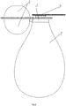
- an inflating device including a valve body 1 and a gasbag 2, the valve body 1 being provided with a gas inlet 101, a gas outlet 102 and a gas storage chamber 103; the gas inlet 101 has a gas intake valve device 400 provided therein, and the gas outlet 102 has a gas exhaust valve device 300 provided therein; the gas storage chamber 103 is communicated with the gasbag 2.
- the gas inlet 101 is communicated with the gas outlet 102 through a chamber body 104 of the valve body 1, and the gas storage chamber 103 is communicated with the chamber body 104.
- the gasbag 2 is a sphere when in a natural state.
- the gas exhaust valve device 300 includes a gas exhaust valve base 310 having a gas exhaust valve through hole 311 provided therein, and a gas exhaust valve ring 312 is provided in the gas exhaust valve through hole 311; the gas exhaust valve ring 312 is connected to a wall of the gas exhaust valve through hole 311 by at least two gas exhaust valve supporting bars 313, and the gas exhaust valve base 310, the gas exhaust valve ring 312 and the gas exhaust valve supporting bars 313 are integrated. In this embodiment, there are three gas exhaust valve supporting bars 313. Of course, there may be two or more gas exhaust valve supporting bars 313.
- the gas exhaust valve core 320 passes through and may be axially moveable in an inner hole 314 of the gas exhaust valve ring 312.
- the outer end of the gas exhaust valve core 320 is connected with a gas exhaust valve seal 340, an annular slope 315 is provided at an outer end of the gas exhaust valve through hole 311, the shape and size of the annular slope 315 are matched with those of the gas exhaust valve seal 340, and the gas exhaust valve spring 330 enables the gas exhaust valve seal 340 to seal the gas exhaust valve through hole 311 after coming into close contact with the annular slope 315.
- the gas exhaust valve seal 340 is, just like a conventional seal, made of elastic plastic.
- the gas intake valve device 400 includes a gas intake valve base 410 having a gas intake valve through hole 411 provided therein, and a gas intake valve ring 412 is provided in the gas intake valve through hole 411; and the gas intake valve ring 412 is connected to a wall of the gas intake valve through hole 411 by at least two gas intake valve supporting bars 413, and the gas intake valve base 410, the gas intake valve ring 412 and the gas intake valve supporting bars 413 are integrated.
- a gas intake valve core 420 passes through and may be axially movable in an inner hole 414 of the gas intake valve ring 412; an annular protrusion 421, which is larger than the inner hole 414 of the gas intake valve ring 412 and radially faces outward, is provided on an outer end of the gas intake valve core 420, an inner end of the gas intake valve core 420 is connected with a gas intake valve raised-bonnet 422 which is larger than the inner hole 414 of the gas intake valve ring 412, and the gas intake valve ring 412 is positioned between the annular protrusion 421 and the gas intake valve raised-bonnet 422.
- a gas intake valve spring 430 is provided between the gas intake valve raised-bonnet 422 and the gas intake valve ring 412, and the inner end of the gas intake valve core 420 passes through the gas intake valve spring 430; and the outer end of the gas intake valve core 420 faces the chamber body 104 of the valve body 1, and the inner end of the gas intake valve core 420 faces outside the valve body 1.
- the outer end of the gas intake valve core 420 is connected with a gas intake valve seal 440, an annular slope 415 is provided at an outer end of the gas intake valve through hole 411, the shape and size of the annular slope 415 are matched with those of the gas intake valve seal 440, and the gas intake valve spring 430 enables the gas intake valve seal 440 to seal the gas intake valve through hole 411 after coming into close contact with the annular slope 415; and the outer end of the gas intake valve through hole 411 faces the chamber body 104 of the valve body 1, and the inner end of the gas intake valve through hole 411 faces outside the valve body 1.
- the gas intake valve seal 440 is, just like a conventional seal, made of plastic.
- the inner end of the gas intake valve through hole 411 is connected with a lid 5 which is used for preventing the gas within an object to be inflated from leaking.
- the gas exhaust valve through hole 311 and the gas intake valve through hole 411 share one axis; there is a gap between the gas exhaust valve raised-bonnet 322 and the gas intake valve seal 440, the gas intake valve core 420 can move the gas exhaust valve core 320 through the gas intake valve seal 440 to open the gas outlet 102 when the gas intake valve core 420 is pressed in a direction from the gas intake valve through hole 411 to the chamber body 104 of the valve body 1.
- the valve body 1 is constituted of a casing 105 and a side bonnet 106 connected to each other, the gas outlet 102 is arranged within the casing 105, and the gas inlet 101 is arranged on the side bonnet 106.
- the gas exhaust valve base 310 is provided with a round step 316 which is positioned within the casing 105 and closely fitted with an inner wall of the casing 105.
- the gas exhaust valve base 310 is provided with a gas exhaust valve plug-in member 7,
- the gas intake valve base 410 is provided with a gas intake valve plug-in member 8 corresponding to and being coordinated with the gas exhaust valve plug-in member 7, and the gas exhaust valve plug-in member 7 is in plug-in connection to the gas intake valve plug-in member 8; and a hole 81 is formed on the gas intake valve plug-in member 8, and the gas exhaust valve plug-in member 7 is inserted into the hole 81 of the gas intake valve plug-in member 8 to realize the plug-in connection. In this way, it is conducive to positioning and fixing the two bases.
- an extension portion 341 is provided on an inner side of the gas exhaust valve seal 340, and the extension portion 341 is an elastomer; one end, far away from the gas exhaust valve seal 340, of the extension portion 341 is a distal end of the extension portion 341; and the distal end has a bump 342 radially facing outward, the bump 342 is positioned within a slot 324 of the gas exhaust valve core 320 after passing through the inner hole 323 of the gas exhaust valve core 320, and the bump 342 is larger than the inner hole 323 of the gas exhaust valve core 320.
- An extension portion 441 is provided on an inner side of the gas intake valve seal 440, and the extension portion 441 is an elastomer; one end, far away from the gas intake value seal 440, of the extension portion 441 is a distal end of the extension portion 441; and the distal end has a bump 442 radially facing outward, the bump 442 is positioned within a slot 424 of the gas intake valve core after passing through the inner hole 423 of the gas intake valve core 420, and the bump 442 is larger than the inner hole 423 of the gas intake valve core 420.
- the gasbag 2 is positioned beside the valve body 1, and the gasbag 2 is positioned beside a central axis of the gas outlet 102 and a central axis of the gas inlet 101.
- FIG. 7 and FIG. 8 are schematic diagrams of a use state when gas is being fed.
- the object 9 is an object to be inflated.
- the gas exhaust valve base 310 is connected to the object 9 to be inflated in a sealed manner.
- the lid 5 may be opened, the gasbag 2 is pressed and the gas pressure inside the chamber body 104 is thus increased, and the gas intake valve seal 440 firmly presses the annular slope 415 due to the gas pressure, so that the gas inlet 101 is kept closed; and the gas pressure acts on the gas exhaust valve raised-bonnet 322, so that the body of the gas exhaust valve core 320 moves outward against the elasticity of the gas exhaust valve spring 330.
- a gap is formed between the gas exhaust valve seal 340 and the annular slope 315, and the gas in the gasbag 2 is fed into the object to be inflated from the gap after passing through the gas storage chamber 103, the chamber body 104 and the gas outlet 102.
- the gasbag 2 expands outward when it is released.
- the negative pressure effect occurs, the gas exhaust valve seal 340 and the annular slope 315 are firmly closed, and the gas outlet 102 is closed; and the gas intake valve core 420 moves towards the gas exhaust valve core 320 against the elasticity of the gas intake valve spring 430 due to the ambient pressure.
- a gap is formed between the gas intake valve seal 440 and the annular slop 415, and the external gas enters the chamber body 104 from the gas inlet 101 and then enters the gasbag 2 after passing through the gas storage chamber 103 until the gasbag 2 expands to the natural state. Then, the gasbag 2 is pressed again, and the gas will be fed into the object to be inflated. Gas is continuously fed by repeating this process.
- the inflating device of the invention has a small volume and a simple structure, and is convenient to use. The manual operation is easy.
- the gas intake valve raised-bonnet 422 is pressed, so that the gas intake valve core moves towards the gas exhaust valve core 320 against the elasticity of the gas intake valve spring 430.
- a gap is formed between the gas intake valve seal 440 and the annular slope 415.
- the gas intake valve seal 440 bears against the gas exhaust valve spring fixing lid 322, so that the gas exhaust valve core 320 moves outward against the elasticity of the gas exhaust valve spring 330.
- a gap is formed between the gas exhaust valve seal 340 and the annular slope 315, and the gas in the object to be deflated comes out from the gap after passing through the gas outlet and the gas inlet, the deflating is thus realized.
- the deflating is convenient, the manual control is simple, the manufacture is easy, and it is convenient to adjust the gas pressure of inflatable products and to deflate the inflatable products.
Landscapes
- Engineering & Computer Science (AREA)
- Mechanical Engineering (AREA)
- General Engineering & Computer Science (AREA)
- Check Valves (AREA)
- Safety Valves (AREA)
- Compressors, Vaccum Pumps And Other Relevant Systems (AREA)
- Fuel-Injection Apparatus (AREA)
- Multiple-Way Valves (AREA)
Claims (8)
- Dispositif de gonflage, comprenant un corps de soupape (1) et un sac à gaz (2), le corps de soupape (1) étant muni d'une entrée de gaz (101), d'une sortie de gaz (102) et d'une chambre de stockage de gaz (103); dans lequel l'entrée de gaz (101) comporte un dispositif de soupape d'admission de gaz (400), et la sortie de gaz (102) comporte un dispositif à soupape de gaz (300), la chambre de stockage de gaz (103) étant en communication avec le sac de gaz (2); l'entrée de gaz (101) est en communication avec la sortie de gaz (102) à travers un corps de chambre (104) du corps de soupape (1), et la chambre de stockage de gaz (103) est en communication avec le corps de chambre (104); dans lequel le dispositif de soupape d'échappement de gaz (300) comprend une base de soupape d'échappement de gaz (310) ayant une soupape d'échappement de gaz traversant un trou (311) prévu dans celle-ci, dispositif caractérisé en ce que le dispositif de soupape d'échappement de gaz (300) comprend
une bague de soupape d'échappement de gaz (312) prévue dans le trou traversant (311) de la soupape d'échappement de gaz; et la bague de soupape d'échappement de gaz (312) est reliée à une paroi de la soupape d'échappement de gaz par le trou traversant (311) par au moins deux barres (313) supportant la soupape d'échappement de gaz, et le fond (310) de soupape d'échappement de gaz, la bague (312) de soupape d'échappement de gaz et les barres support (313) des soupape d'échappement de gaz étant intégrés;
un noyau de soupape d'échappement de gaz (320) passe à travers et peut se déplacer axialement dans un trou intérieur (314) de la bague de soupape d'échappement de gaz (312); une protubérance annulaire (321), qui est plus grande que le trou intérieur (314) de la bague de soupape d'échappement de gaz (312) et orientée radialement vers l'extérieur, est prévue sur une extrémité extérieure du noyau de soupape d'échappement de gaz (320), une extrémité intérieure du noyau de soupape d'échappement de gaz (320) est reliée à un chapeau surélevé de soupape d'échappement de gaz (322) qui est plus grand que le trou intérieur (314) de la bague de soupape d'échappement de gaz (312), et la bague de soupape d'échappement de gaz (312) est placée entre la protubérance annulaire (321) et le chapeau surélevé de soupape d'échappement de gaz (322); un ressort de soupape d'échappement de gaz (330) est prévu entre le chapeau surélevé (322) de soupape d'échappement de gaz et la bague de soupape d'échappement de gaz (312), et l'extrémité intérieure du noyau (320) de soupape d'échappement de gaz traverse le ressort de soupape d'échappement de gaz (330); et l'extrémité extérieure du noyau de soupape d'échappement de gaz (320) fait face vers l'extérieur au corps de soupape (1) et l'extrémité interne du noyau (320) de soupape d'échappement de gaz fait face au corps (104) de la chambre de soupape (1). - Dispositif de gonflage selon la revendication 1, dans lequel l'extrémité extérieure du noyau de la soupape d'échappement de gaz (320) est reliée à un joint de soupape d'échappement de gaz (340), une pente annulaire (315) est prévue à une extrémité extérieure du trou de passage de la soupape d'échappement de gaz (311), la forme et la dimension de la pente annulaire (315) sont adaptées à celles du joint de soupape de gaz (340) et le ressort du dispositif d'évacuation de gaz (330) permet à la soupape d'évacuation de gaz (340) de remplir un trou traversant de soupape d'échappement de gaz (311) après contact proche avec la pente annulaire (315).
- Dispositif de gonflage selon la revendication 2, dans lequel une partie d'extension (341) est prévue sur un côté intérieur du joint de la soupape d'échappement de gaz (340), et la partie d'extension (341) est un élastomère; une extrémité, éloignée du joint de la soupape d'échappement de gaz (340), de la partie d'extension (341) est une extrémité distale de la partie d'extension (341); et l'extrémité distale présente une bosse (342) orientée radialement vers l'extérieur, la bosse (342) est positionnée dans une fente (324) du noyau de la soupape d'échappement de gaz (320) après avoir traversé le trou intérieur (323) du noyau de la soupape d'échappement de gaz (320), et la bosse (342) est plus grande que le trou intérieur (323) du noyau de soupape d'échappement de gaz (320).
- Dispositif de gonflage selon la revendication 1, dans lequel le dispositif de soupape d'admission de gaz (400) comprend une base de soupape d'admission de gaz (410) ayant une soupape d'admission de gaz traversant l'orifice (411), et une bague de soupape d'admission de gaz (412) est prévue dans le trou traversant (411) de la soupape d'admission de gaz; et la bague de soupape d'admission de gaz (412) est reliée à une paroi de la soupape d'admission de gaz par au moins deux barres de support (413) de soupape d'admission de gaz, et la base de soupape d'admission de gaz (410), la bague de soupape d'admission de gaz (412) et les barres de support de soupape d'admission de gaz (413) sont intégrées;
un noyau de soupape d'échappement de gaz (420) passe à travers et peut se déplacer axialement dans un trou intérieur (414) de la bague de soupape d'échappement de gaz (412); une protubérance annulaire (421), qui est plus grande que le trou intérieur (414) de la bague de soupape d'admission de gaz (412) et orientée radialement vers l'extérieur, est prévue sur une extrémité extérieure du noyau de soupape d'admission de gaz (420), une extrémité intérieure du noyau de soupape d'admission de gaz (420) est reliée à un chapeau surélevé de soupape d'admission de gaz (422) qui est plus grand que le trou intérieur (414) de la bague de soupape d'admission de gaz (412), et la bague de soupape d'admission de gaz (412) est placée entre la protubérance annulaire (421) et le chapeau surélevé de soupape d'admission de gaz (422); un ressort de soupape d'admission de gaz (430) est prévu entre le chapeau surélevé de soupape d'admission de gaz (422) et la bague de soupape d'admission de gaz (412), et l'extrémité intérieure du noyau de soupape d'admission de gaz (420) traverse le ressort de soupape d'admission de gaz (430); et l'extrémité extérieure du noyau de soupape d'admission de gaz (420) fait face au corps de chambre (104) du boîtier de soupape (1) et l'extrémité intérieure du noyau (420) de soupape d'admission de gaz est face à l'extérieur du corps du soupape (1). - Dispositif de gonflage selon la revendication 4, dans lequel l'extrémité extérieure du noyau (420) de la soupape d'admission de gaz est reliée à un joint de soupape d'admission de gaz (440), une pente annulaire (415) est prévue à une extrémité extérieure du trou traversant de la soupape d'admission de gaz (411), la forme et la dimension de la pente annulaire (415) sont adaptées à celles du joint de soupape d'admission de gaz (440), et le ressort (430) permet au joint de soupape d'admission de gaz (440) de fermer le trou traversant de soupape d'admission de gaz (411) après son approche de la pente annulaire (415) et l'extrémité extérieure de la soupape d'admission de gaz (411) fait face au corps de chambre (104) du corps de soupape (1), et l'extrémité intérieure du trou traversant de soupape d'admission de gaz (411) fait face à l'extérieur du corps de soupape (1).
- Dispositif de gonflage selon la revendication 1, dans lequel la base de soupape d'échappement de gaz (310) est munie d'un élément enfichable de soupape d'échappement de gaz (7), la base de soupape d'admission de gaz (410) est munie d'un élément enfichable de soupape d'admission de gaz (8) correspondant à l'élément enfichable de soupape d'échappement de gaz (7) et étant adapté avec celui-ci, l'élément enfichable de soupape d'échappement de gaz (7) est en liaison enfichable à l'élément enfichable de soupape d'admission de gaz (8).
- Dispositif de gonflage selon la revendication 5, dans lequel la soupape d'échappement de gaz par le trou traversant (311) et le trou traversant de soupape d'admission de gaz (411) partagent un axe; il y a un espace entre le chapeau surélevé de la soupape d'échappement de gaz (322) et le joint de la soupape d'admission de gaz (440), le noyau de la soupape d'admission de gaz (420) peut déplacer le noyau de la soupape d'échappement de gaz (320) par le joint de soupape d'admission de gaz (440) pour ouvrir la sortie de gaz (440) lorsque le noyau de soupape d'admission de gaz est comprimé dans une direction allant du trou traversant de la soupape d'entrée de gaz (411) au corps de chambre (104) de la chambre de la soupape (1).
- Dispositif de gonflage selon la revendication 5, dans lequel une partie d'extension (441) est prévue sur un côté intérieur du joint de soupape d'échappement de gaz (440), et la partie d'extension (441) est un élastomère; une extrémité, éloignée du joint de la soupape d'échappement de gaz (440), de la partie d'extension (441) est une extrémité distale de la partie d'extension (441); et l'extrémité distale présente une bosse (442) orientée radialement vers l'extérieur, la bosse (442) est positionnée dans une fente (424) du noyau de la soupape d'échappement de gaz (420) après avoir traversé le trou intérieur (423) du noyau de la soupape d'échappement de gaz (420), et la bosse (442) est plus grande que le trou intérieur (423) du noyau de soupape d'échappement de gaz (420).
Priority Applications (1)
| Application Number | Priority Date | Filing Date | Title |
|---|---|---|---|
| EP19193918.0A EP3591227B1 (fr) | 2014-10-09 | 2014-10-28 | Dispositif de gonflage |
Applications Claiming Priority (2)
| Application Number | Priority Date | Filing Date | Title |
|---|---|---|---|
| CN201420581671.7U CN204175545U (zh) | 2014-10-09 | 2014-10-09 | 充气装置 |
| PCT/CN2014/000952 WO2016054761A1 (fr) | 2014-10-09 | 2014-10-28 | Dispositif de gonflage |
Related Child Applications (2)
| Application Number | Title | Priority Date | Filing Date |
|---|---|---|---|
| EP19193918.0A Division-Into EP3591227B1 (fr) | 2014-10-09 | 2014-10-28 | Dispositif de gonflage |
| EP19193918.0A Division EP3591227B1 (fr) | 2014-10-09 | 2014-10-28 | Dispositif de gonflage |
Publications (3)
| Publication Number | Publication Date |
|---|---|
| EP3205879A1 EP3205879A1 (fr) | 2017-08-16 |
| EP3205879A4 EP3205879A4 (fr) | 2018-07-11 |
| EP3205879B1 true EP3205879B1 (fr) | 2019-12-18 |
Family
ID=52564356
Family Applications (2)
| Application Number | Title | Priority Date | Filing Date |
|---|---|---|---|
| EP14903584.2A Active EP3205879B1 (fr) | 2014-10-09 | 2014-10-28 | Dispositif de gonflage |
| EP19193918.0A Active EP3591227B1 (fr) | 2014-10-09 | 2014-10-28 | Dispositif de gonflage |
Family Applications After (1)
| Application Number | Title | Priority Date | Filing Date |
|---|---|---|---|
| EP19193918.0A Active EP3591227B1 (fr) | 2014-10-09 | 2014-10-28 | Dispositif de gonflage |
Country Status (7)
| Country | Link |
|---|---|
| US (2) | US10641258B2 (fr) |
| EP (2) | EP3205879B1 (fr) |
| JP (2) | JP6505118B2 (fr) |
| KR (2) | KR102128313B1 (fr) |
| CN (3) | CN204175545U (fr) |
| CH (1) | CH711877B1 (fr) |
| WO (1) | WO2016054761A1 (fr) |
Families Citing this family (10)
| Publication number | Priority date | Publication date | Assignee | Title |
|---|---|---|---|---|
| CN204175545U (zh) * | 2014-10-09 | 2015-02-25 | 刘志明 | 充气装置 |
| CN104279137B (zh) * | 2014-10-09 | 2016-08-31 | 刘志明 | 充气装置 |
| USD854355S1 (en) * | 2017-04-05 | 2019-07-23 | Huizhou Miaosite Industrial Co., Ltd. | Inflatable pillow |
| US10539125B2 (en) * | 2017-04-15 | 2020-01-21 | Chi-Yuan Chang | Manual pump |
| CN107013434A (zh) * | 2017-06-05 | 2017-08-04 | 惠州市锦恒工业模具设计合伙企业(普通合伙) | 一种快速充气装置 |
| CN108720101B (zh) * | 2018-05-07 | 2020-10-13 | 福建柒牌时装科技股份有限公司 | 智能西服 |
| CN113474632A (zh) * | 2019-02-25 | 2021-10-01 | 株式会社岛津制作所 | 气体检查装置中的气体供给部的清洗方法 |
| CN111022290A (zh) * | 2019-11-28 | 2020-04-17 | 宁波洛孚纳克塑业有限公司 | 一种便携型按压式气泵 |
| CN111577939B (zh) * | 2020-05-12 | 2021-09-14 | 成都海申科技有限公司 | 一种调压止回卸荷组合溢流阀 |
| CN117869257A (zh) * | 2023-12-29 | 2024-04-12 | 海南泽彬科技贸易有限公司 | 一种充气装置 |
Family Cites Families (24)
| Publication number | Priority date | Publication date | Assignee | Title |
|---|---|---|---|---|
| US1779421A (en) * | 1928-05-26 | 1930-10-28 | Ora C Cox | Check valve |
| US3068494A (en) * | 1961-01-16 | 1962-12-18 | Monroe Fabricators Inc | Air pump for inflatable structures |
| US3995653A (en) * | 1975-08-01 | 1976-12-07 | Mackal Glenn H | Inflation device |
| DE3319869A1 (de) * | 1982-08-19 | 1984-02-23 | Itw-Ateco Gmbh, 2000 Norderstedt | Fuell- und entleerungsventil fuer aufblasbare hohlkoerper |
| JPS60125961U (ja) * | 1984-01-30 | 1985-08-24 | トヨタ車体株式会社 | エア供給装置 |
| US5074765A (en) * | 1990-04-13 | 1991-12-24 | Dielectrics Industries | Elastomeric air pump |
| US5226793A (en) * | 1991-05-23 | 1993-07-13 | Stovall Kalena D | Balloon pump |
| CA2126869A1 (fr) * | 1992-11-09 | 1994-05-26 | David Freni | Mecanisme de gonflage pour article gonflable |
| US5556258A (en) * | 1995-06-12 | 1996-09-17 | Lange; Robert F. | Squeezebulb operated sports ball pump |
| US6730017B2 (en) * | 2000-12-27 | 2004-05-04 | Ams Research Corporation | Pressure based spontaneous inflation inhibitor with penile pump improvements |
| US6581626B2 (en) * | 2001-06-28 | 2003-06-24 | Zurn Industries, Inc. | Backflow prevention apparatus |
| US6923202B2 (en) * | 2002-06-01 | 2005-08-02 | Halkey-Roberts Corporation | Modular pressure relief valve |
| US20070071623A1 (en) * | 2005-09-23 | 2007-03-29 | Chi-Yuan Chang | Pump structure easily and quickly connectable with an air cushion or a bladder |
| US20080047612A1 (en) * | 2006-08-22 | 2008-02-28 | Wcm Industries, Inc. | Automatic draining double check vacuum breaker |
| CN100547241C (zh) * | 2007-01-31 | 2009-10-07 | 刘志明 | 一种充气装置 |
| JP2009022335A (ja) * | 2007-07-17 | 2009-02-05 | Kozo Oshio | 耳の掃除具 |
| CN201069009Y (zh) * | 2007-08-15 | 2008-06-04 | 黄韶武 | 一种用于充气式物品上的阀门装置 |
| CN201772115U (zh) * | 2010-01-08 | 2011-03-23 | 中山喜玛拉雅塑胶制品有限公司 | 充气阀 |
| TWM389448U (en) * | 2010-05-27 | 2010-10-01 | Universal Trim Supply Co Ltd | Structure for airbag-squeezing device |
| CN102895713B (zh) * | 2012-07-12 | 2014-12-17 | 三峡大学第一临床医学院 | 自动滴注装置 |
| TW201433275A (zh) * | 2013-02-22 | 2014-09-01 | Universal Trim Supply Co Ltd | 簡易式充氣閥構造 |
| CN103485999A (zh) * | 2013-09-18 | 2014-01-01 | 中山骏宏塑胶制品有限公司 | 一种双向充气泵 |
| CN204175545U (zh) * | 2014-10-09 | 2015-02-25 | 刘志明 | 充气装置 |
| CN104279137B (zh) * | 2014-10-09 | 2016-08-31 | 刘志明 | 充气装置 |
-
2014
- 2014-10-09 CN CN201420581671.7U patent/CN204175545U/zh not_active Expired - Lifetime
- 2014-10-28 EP EP14903584.2A patent/EP3205879B1/fr active Active
- 2014-10-28 JP JP2016548247A patent/JP6505118B2/ja active Active
- 2014-10-28 CN CN201480079311.XA patent/CN107002651B/zh not_active Ceased
- 2014-10-28 CH CH00476/17A patent/CH711877B1/fr unknown
- 2014-10-28 US US15/036,049 patent/US10641258B2/en active Active
- 2014-10-28 EP EP19193918.0A patent/EP3591227B1/fr active Active
- 2014-10-28 CN CN201810601059.4A patent/CN109058063B/zh not_active Ceased
- 2014-10-28 WO PCT/CN2014/000952 patent/WO2016054761A1/fr not_active Ceased
- 2014-10-28 KR KR1020197009046A patent/KR102128313B1/ko active Active
- 2014-10-28 KR KR1020177007570A patent/KR20170043630A/ko not_active Ceased
-
2018
- 2018-07-11 US US16/033,130 patent/US11085432B2/en active Active
-
2019
- 2019-03-26 JP JP2019059239A patent/JP6763050B2/ja active Active
Non-Patent Citations (1)
| Title |
|---|
| None * |
Also Published As
| Publication number | Publication date |
|---|---|
| US10641258B2 (en) | 2020-05-05 |
| EP3205879A1 (fr) | 2017-08-16 |
| US20170107980A1 (en) | 2017-04-20 |
| CN109058063B (zh) | 2020-04-17 |
| CN109058063A (zh) | 2018-12-21 |
| JP2019116898A (ja) | 2019-07-18 |
| CN107002651A (zh) | 2017-08-01 |
| JP2017532472A (ja) | 2017-11-02 |
| KR20190038676A (ko) | 2019-04-08 |
| CN107002651B (zh) | 2018-07-06 |
| JP6763050B2 (ja) | 2020-09-30 |
| EP3205879A4 (fr) | 2018-07-11 |
| CN204175545U (zh) | 2015-02-25 |
| US20180320675A1 (en) | 2018-11-08 |
| EP3591227A1 (fr) | 2020-01-08 |
| KR20170043630A (ko) | 2017-04-21 |
| US11085432B2 (en) | 2021-08-10 |
| WO2016054761A1 (fr) | 2016-04-14 |
| KR102128313B1 (ko) | 2020-07-08 |
| EP3591227B1 (fr) | 2020-08-19 |
| JP6505118B2 (ja) | 2019-04-24 |
| CH711877B1 (fr) | 2021-02-26 |
Similar Documents
| Publication | Publication Date | Title |
|---|---|---|
| EP3591227B1 (fr) | Dispositif de gonflage | |
| CN108661879B (zh) | 微型充气装置 | |
| CN104279137B (zh) | 充气装置 | |
| CN109480533A (zh) | 一种充气床 | |
| CN104481853A (zh) | 便携式充气装置 | |
| CN114542776B (zh) | 可充放气的空气阀 | |
| CN207796213U (zh) | 充气装置 | |
| HK40014890B (en) | Inflating device | |
| HK40014890A (en) | Inflating device | |
| HK1239778B (en) | Inflation device | |
| HK1239778A1 (en) | Inflation device | |
| CN216923351U (zh) | 可充放气的空气阀 | |
| CN103821983B (zh) | 一种气嘴 | |
| CN203718088U (zh) | 一种气嘴 | |
| CN206144764U (zh) | 简易充气装置 | |
| CN202056364U (zh) | 一种密封性好的风嘴 | |
| CN204371619U (zh) | 便携式充气装置 | |
| HK40001475A (en) | An inflating device | |
| HK40001475B (en) | An inflating device | |
| CN110792583B (zh) | 一种充气装置及充气件 | |
| CN209360152U (zh) | 一种充气床 | |
| CN204553972U (zh) | 一种充气阀 | |
| CN221743283U (zh) | 一种充放气门阀 | |
| CN206802428U (zh) | 一种快速充放气阀 | |
| CN204985880U (zh) | 充气大气阀 |
Legal Events
| Date | Code | Title | Description |
|---|---|---|---|
| STAA | Information on the status of an ep patent application or granted ep patent |
Free format text: STATUS: THE INTERNATIONAL PUBLICATION HAS BEEN MADE |
|
| PUAI | Public reference made under article 153(3) epc to a published international application that has entered the european phase |
Free format text: ORIGINAL CODE: 0009012 |
|
| STAA | Information on the status of an ep patent application or granted ep patent |
Free format text: STATUS: REQUEST FOR EXAMINATION WAS MADE |
|
| 17P | Request for examination filed |
Effective date: 20170505 |
|
| AK | Designated contracting states |
Kind code of ref document: A1 Designated state(s): AL AT BE BG CH CY CZ DE DK EE ES FI FR GB GR HR HU IE IS IT LI LT LU LV MC MK MT NL NO PL PT RO RS SE SI SK SM TR |
|
| AX | Request for extension of the european patent |
Extension state: BA ME |
|
| DAX | Request for extension of the european patent (deleted) | ||
| REG | Reference to a national code |
Ref country code: HK Ref legal event code: DE Ref document number: 1239778 Country of ref document: HK |
|
| A4 | Supplementary search report drawn up and despatched |
Effective date: 20180608 |
|
| RIC1 | Information provided on ipc code assigned before grant |
Ipc: F04B 45/00 20060101ALI20180604BHEP Ipc: F04B 33/00 20060101AFI20180604BHEP Ipc: F04B 39/10 20060101ALI20180604BHEP Ipc: F04B 45/02 20060101ALI20180604BHEP |
|
| STAA | Information on the status of an ep patent application or granted ep patent |
Free format text: STATUS: EXAMINATION IS IN PROGRESS |
|
| 17Q | First examination report despatched |
Effective date: 20190405 |
|
| GRAP | Despatch of communication of intention to grant a patent |
Free format text: ORIGINAL CODE: EPIDOSNIGR1 |
|
| STAA | Information on the status of an ep patent application or granted ep patent |
Free format text: STATUS: GRANT OF PATENT IS INTENDED |
|
| INTG | Intention to grant announced |
Effective date: 20190723 |
|
| GRAS | Grant fee paid |
Free format text: ORIGINAL CODE: EPIDOSNIGR3 |
|
| GRAA | (expected) grant |
Free format text: ORIGINAL CODE: 0009210 |
|
| STAA | Information on the status of an ep patent application or granted ep patent |
Free format text: STATUS: THE PATENT HAS BEEN GRANTED |
|
| AK | Designated contracting states |
Kind code of ref document: B1 Designated state(s): AL AT BE BG CH CY CZ DE DK EE ES FI FR GB GR HR HU IE IS IT LI LT LU LV MC MK MT NL NO PL PT RO RS SE SI SK SM TR |
|
| REG | Reference to a national code |
Ref country code: CH Ref legal event code: EP |
|
| REG | Reference to a national code |
Ref country code: IE Ref legal event code: FG4D |
|
| REG | Reference to a national code |
Ref country code: DE Ref legal event code: R096 Ref document number: 602014058782 Country of ref document: DE |
|
| REG | Reference to a national code |
Ref country code: AT Ref legal event code: REF Ref document number: 1214891 Country of ref document: AT Kind code of ref document: T Effective date: 20200115 |
|
| REG | Reference to a national code |
Ref country code: CH Ref legal event code: NV Representative=s name: MEYER AND KOLLEGEN, CH |
|
| REG | Reference to a national code |
Ref country code: NL Ref legal event code: MP Effective date: 20191218 |
|
| PG25 | Lapsed in a contracting state [announced via postgrant information from national office to epo] |
Ref country code: LV Free format text: LAPSE BECAUSE OF FAILURE TO SUBMIT A TRANSLATION OF THE DESCRIPTION OR TO PAY THE FEE WITHIN THE PRESCRIBED TIME-LIMIT Effective date: 20191218 Ref country code: SE Free format text: LAPSE BECAUSE OF FAILURE TO SUBMIT A TRANSLATION OF THE DESCRIPTION OR TO PAY THE FEE WITHIN THE PRESCRIBED TIME-LIMIT Effective date: 20191218 Ref country code: LT Free format text: LAPSE BECAUSE OF FAILURE TO SUBMIT A TRANSLATION OF THE DESCRIPTION OR TO PAY THE FEE WITHIN THE PRESCRIBED TIME-LIMIT Effective date: 20191218 Ref country code: GR Free format text: LAPSE BECAUSE OF FAILURE TO SUBMIT A TRANSLATION OF THE DESCRIPTION OR TO PAY THE FEE WITHIN THE PRESCRIBED TIME-LIMIT Effective date: 20200319 Ref country code: NO Free format text: LAPSE BECAUSE OF FAILURE TO SUBMIT A TRANSLATION OF THE DESCRIPTION OR TO PAY THE FEE WITHIN THE PRESCRIBED TIME-LIMIT Effective date: 20200318 Ref country code: FI Free format text: LAPSE BECAUSE OF FAILURE TO SUBMIT A TRANSLATION OF THE DESCRIPTION OR TO PAY THE FEE WITHIN THE PRESCRIBED TIME-LIMIT Effective date: 20191218 Ref country code: BG Free format text: LAPSE BECAUSE OF FAILURE TO SUBMIT A TRANSLATION OF THE DESCRIPTION OR TO PAY THE FEE WITHIN THE PRESCRIBED TIME-LIMIT Effective date: 20200318 |
|
| REG | Reference to a national code |
Ref country code: LT Ref legal event code: MG4D |
|
| PG25 | Lapsed in a contracting state [announced via postgrant information from national office to epo] |
Ref country code: HR Free format text: LAPSE BECAUSE OF FAILURE TO SUBMIT A TRANSLATION OF THE DESCRIPTION OR TO PAY THE FEE WITHIN THE PRESCRIBED TIME-LIMIT Effective date: 20191218 Ref country code: RS Free format text: LAPSE BECAUSE OF FAILURE TO SUBMIT A TRANSLATION OF THE DESCRIPTION OR TO PAY THE FEE WITHIN THE PRESCRIBED TIME-LIMIT Effective date: 20191218 |
|
| PG25 | Lapsed in a contracting state [announced via postgrant information from national office to epo] |
Ref country code: AL Free format text: LAPSE BECAUSE OF FAILURE TO SUBMIT A TRANSLATION OF THE DESCRIPTION OR TO PAY THE FEE WITHIN THE PRESCRIBED TIME-LIMIT Effective date: 20191218 |
|
| PG25 | Lapsed in a contracting state [announced via postgrant information from national office to epo] |
Ref country code: CZ Free format text: LAPSE BECAUSE OF FAILURE TO SUBMIT A TRANSLATION OF THE DESCRIPTION OR TO PAY THE FEE WITHIN THE PRESCRIBED TIME-LIMIT Effective date: 20191218 Ref country code: RO Free format text: LAPSE BECAUSE OF FAILURE TO SUBMIT A TRANSLATION OF THE DESCRIPTION OR TO PAY THE FEE WITHIN THE PRESCRIBED TIME-LIMIT Effective date: 20191218 Ref country code: PT Free format text: LAPSE BECAUSE OF FAILURE TO SUBMIT A TRANSLATION OF THE DESCRIPTION OR TO PAY THE FEE WITHIN THE PRESCRIBED TIME-LIMIT Effective date: 20200513 Ref country code: EE Free format text: LAPSE BECAUSE OF FAILURE TO SUBMIT A TRANSLATION OF THE DESCRIPTION OR TO PAY THE FEE WITHIN THE PRESCRIBED TIME-LIMIT Effective date: 20191218 Ref country code: NL Free format text: LAPSE BECAUSE OF FAILURE TO SUBMIT A TRANSLATION OF THE DESCRIPTION OR TO PAY THE FEE WITHIN THE PRESCRIBED TIME-LIMIT Effective date: 20191218 |
|
| PG25 | Lapsed in a contracting state [announced via postgrant information from national office to epo] |
Ref country code: IS Free format text: LAPSE BECAUSE OF FAILURE TO SUBMIT A TRANSLATION OF THE DESCRIPTION OR TO PAY THE FEE WITHIN THE PRESCRIBED TIME-LIMIT Effective date: 20200418 Ref country code: SK Free format text: LAPSE BECAUSE OF FAILURE TO SUBMIT A TRANSLATION OF THE DESCRIPTION OR TO PAY THE FEE WITHIN THE PRESCRIBED TIME-LIMIT Effective date: 20191218 Ref country code: SM Free format text: LAPSE BECAUSE OF FAILURE TO SUBMIT A TRANSLATION OF THE DESCRIPTION OR TO PAY THE FEE WITHIN THE PRESCRIBED TIME-LIMIT Effective date: 20191218 |
|
| REG | Reference to a national code |
Ref country code: DE Ref legal event code: R097 Ref document number: 602014058782 Country of ref document: DE |
|
| REG | Reference to a national code |
Ref country code: AT Ref legal event code: MK05 Ref document number: 1214891 Country of ref document: AT Kind code of ref document: T Effective date: 20191218 |
|
| PLBE | No opposition filed within time limit |
Free format text: ORIGINAL CODE: 0009261 |
|
| STAA | Information on the status of an ep patent application or granted ep patent |
Free format text: STATUS: NO OPPOSITION FILED WITHIN TIME LIMIT |
|
| PG25 | Lapsed in a contracting state [announced via postgrant information from national office to epo] |
Ref country code: DK Free format text: LAPSE BECAUSE OF FAILURE TO SUBMIT A TRANSLATION OF THE DESCRIPTION OR TO PAY THE FEE WITHIN THE PRESCRIBED TIME-LIMIT Effective date: 20191218 Ref country code: ES Free format text: LAPSE BECAUSE OF FAILURE TO SUBMIT A TRANSLATION OF THE DESCRIPTION OR TO PAY THE FEE WITHIN THE PRESCRIBED TIME-LIMIT Effective date: 20191218 |
|
| 26N | No opposition filed |
Effective date: 20200921 |
|
| PG25 | Lapsed in a contracting state [announced via postgrant information from national office to epo] |
Ref country code: AT Free format text: LAPSE BECAUSE OF FAILURE TO SUBMIT A TRANSLATION OF THE DESCRIPTION OR TO PAY THE FEE WITHIN THE PRESCRIBED TIME-LIMIT Effective date: 20191218 Ref country code: SI Free format text: LAPSE BECAUSE OF FAILURE TO SUBMIT A TRANSLATION OF THE DESCRIPTION OR TO PAY THE FEE WITHIN THE PRESCRIBED TIME-LIMIT Effective date: 20191218 |
|
| PG25 | Lapsed in a contracting state [announced via postgrant information from national office to epo] |
Ref country code: IT Free format text: LAPSE BECAUSE OF FAILURE TO SUBMIT A TRANSLATION OF THE DESCRIPTION OR TO PAY THE FEE WITHIN THE PRESCRIBED TIME-LIMIT Effective date: 20191218 |
|
| PG25 | Lapsed in a contracting state [announced via postgrant information from national office to epo] |
Ref country code: PL Free format text: LAPSE BECAUSE OF FAILURE TO SUBMIT A TRANSLATION OF THE DESCRIPTION OR TO PAY THE FEE WITHIN THE PRESCRIBED TIME-LIMIT Effective date: 20191218 |
|
| PG25 | Lapsed in a contracting state [announced via postgrant information from national office to epo] |
Ref country code: LU Free format text: LAPSE BECAUSE OF NON-PAYMENT OF DUE FEES Effective date: 20201028 Ref country code: MC Free format text: LAPSE BECAUSE OF FAILURE TO SUBMIT A TRANSLATION OF THE DESCRIPTION OR TO PAY THE FEE WITHIN THE PRESCRIBED TIME-LIMIT Effective date: 20191218 |
|
| REG | Reference to a national code |
Ref country code: BE Ref legal event code: MM Effective date: 20201031 |
|
| PG25 | Lapsed in a contracting state [announced via postgrant information from national office to epo] |
Ref country code: BE Free format text: LAPSE BECAUSE OF NON-PAYMENT OF DUE FEES Effective date: 20201031 |
|
| PG25 | Lapsed in a contracting state [announced via postgrant information from national office to epo] |
Ref country code: IE Free format text: LAPSE BECAUSE OF NON-PAYMENT OF DUE FEES Effective date: 20201028 |
|
| PG25 | Lapsed in a contracting state [announced via postgrant information from national office to epo] |
Ref country code: TR Free format text: LAPSE BECAUSE OF FAILURE TO SUBMIT A TRANSLATION OF THE DESCRIPTION OR TO PAY THE FEE WITHIN THE PRESCRIBED TIME-LIMIT Effective date: 20191218 Ref country code: MT Free format text: LAPSE BECAUSE OF FAILURE TO SUBMIT A TRANSLATION OF THE DESCRIPTION OR TO PAY THE FEE WITHIN THE PRESCRIBED TIME-LIMIT Effective date: 20191218 Ref country code: CY Free format text: LAPSE BECAUSE OF FAILURE TO SUBMIT A TRANSLATION OF THE DESCRIPTION OR TO PAY THE FEE WITHIN THE PRESCRIBED TIME-LIMIT Effective date: 20191218 |
|
| PG25 | Lapsed in a contracting state [announced via postgrant information from national office to epo] |
Ref country code: MK Free format text: LAPSE BECAUSE OF FAILURE TO SUBMIT A TRANSLATION OF THE DESCRIPTION OR TO PAY THE FEE WITHIN THE PRESCRIBED TIME-LIMIT Effective date: 20191218 |
|
| PGFP | Annual fee paid to national office [announced via postgrant information from national office to epo] |
Ref country code: GB Payment date: 20231025 Year of fee payment: 10 |
|
| PGFP | Annual fee paid to national office [announced via postgrant information from national office to epo] |
Ref country code: FR Payment date: 20231023 Year of fee payment: 10 Ref country code: DE Payment date: 20230925 Year of fee payment: 10 Ref country code: CH Payment date: 20231102 Year of fee payment: 10 |
|
| REG | Reference to a national code |
Ref country code: DE Ref legal event code: R119 Ref document number: 602014058782 Country of ref document: DE |
|
| REG | Reference to a national code |
Ref country code: CH Ref legal event code: PL |
|
| GBPC | Gb: european patent ceased through non-payment of renewal fee |
Effective date: 20241028 |
|
| PG25 | Lapsed in a contracting state [announced via postgrant information from national office to epo] |
Ref country code: DE Free format text: LAPSE BECAUSE OF NON-PAYMENT OF DUE FEES Effective date: 20250501 |
|
| PG25 | Lapsed in a contracting state [announced via postgrant information from national office to epo] |
Ref country code: GB Free format text: LAPSE BECAUSE OF NON-PAYMENT OF DUE FEES Effective date: 20241028 |
|
| PG25 | Lapsed in a contracting state [announced via postgrant information from national office to epo] |
Ref country code: FR Free format text: LAPSE BECAUSE OF NON-PAYMENT OF DUE FEES Effective date: 20241031 |
|
| PG25 | Lapsed in a contracting state [announced via postgrant information from national office to epo] |
Ref country code: CH Free format text: LAPSE BECAUSE OF NON-PAYMENT OF DUE FEES Effective date: 20241031 |