EP3205884B1 - Système de rotor à vide auto-pompant - Google Patents
Système de rotor à vide auto-pompant Download PDFInfo
- Publication number
- EP3205884B1 EP3205884B1 EP16155415.9A EP16155415A EP3205884B1 EP 3205884 B1 EP3205884 B1 EP 3205884B1 EP 16155415 A EP16155415 A EP 16155415A EP 3205884 B1 EP3205884 B1 EP 3205884B1
- Authority
- EP
- European Patent Office
- Prior art keywords
- gas
- rotor
- vacuum
- removal device
- lateral surface
- Prior art date
- Legal status (The legal status is an assumption and is not a legal conclusion. Google has not performed a legal analysis and makes no representation as to the accuracy of the status listed.)
- Active
Links
Images




Classifications
-
- F—MECHANICAL ENGINEERING; LIGHTING; HEATING; WEAPONS; BLASTING
- F04—POSITIVE - DISPLACEMENT MACHINES FOR LIQUIDS; PUMPS FOR LIQUIDS OR ELASTIC FLUIDS
- F04D—NON-POSITIVE-DISPLACEMENT PUMPS
- F04D17/00—Radial-flow pumps, e.g. centrifugal pumps; Helico-centrifugal pumps
- F04D17/08—Centrifugal pumps
- F04D17/16—Centrifugal pumps for displacing without appreciable compression
- F04D17/168—Pumps specially adapted to produce a vacuum
-
- F—MECHANICAL ENGINEERING; LIGHTING; HEATING; WEAPONS; BLASTING
- F03—MACHINES OR ENGINES FOR LIQUIDS; WIND, SPRING, OR WEIGHT MOTORS; PRODUCING MECHANICAL POWER OR A REACTIVE PROPULSIVE THRUST, NOT OTHERWISE PROVIDED FOR
- F03G—SPRING, WEIGHT, INERTIA OR LIKE MOTORS; MECHANICAL-POWER PRODUCING DEVICES OR MECHANISMS, NOT OTHERWISE PROVIDED FOR OR USING ENERGY SOURCES NOT OTHERWISE PROVIDED FOR
- F03G3/00—Other motors, e.g. gravity or inertia motors
- F03G3/08—Other motors, e.g. gravity or inertia motors using flywheels
-
- F—MECHANICAL ENGINEERING; LIGHTING; HEATING; WEAPONS; BLASTING
- F04—POSITIVE - DISPLACEMENT MACHINES FOR LIQUIDS; PUMPS FOR LIQUIDS OR ELASTIC FLUIDS
- F04D—NON-POSITIVE-DISPLACEMENT PUMPS
- F04D1/00—Radial-flow pumps, e.g. centrifugal pumps; Helico-centrifugal pumps
- F04D1/12—Pumps with scoops or like paring members protruding in the fluid circulating in a bowl
-
- F—MECHANICAL ENGINEERING; LIGHTING; HEATING; WEAPONS; BLASTING
- F04—POSITIVE - DISPLACEMENT MACHINES FOR LIQUIDS; PUMPS FOR LIQUIDS OR ELASTIC FLUIDS
- F04D—NON-POSITIVE-DISPLACEMENT PUMPS
- F04D29/00—Details, component parts, or accessories
- F04D29/26—Rotors specially for elastic fluids
- F04D29/28—Rotors specially for elastic fluids for centrifugal or helico-centrifugal pumps for radial-flow or helico-centrifugal pumps
- F04D29/284—Rotors specially for elastic fluids for centrifugal or helico-centrifugal pumps for radial-flow or helico-centrifugal pumps for compressors
-
- F—MECHANICAL ENGINEERING; LIGHTING; HEATING; WEAPONS; BLASTING
- F16—ENGINEERING ELEMENTS AND UNITS; GENERAL MEASURES FOR PRODUCING AND MAINTAINING EFFECTIVE FUNCTIONING OF MACHINES OR INSTALLATIONS; THERMAL INSULATION IN GENERAL
- F16F—SPRINGS; SHOCK-ABSORBERS; MEANS FOR DAMPING VIBRATION
- F16F15/00—Suppression of vibrations in systems; Means or arrangements for avoiding or reducing out-of-balance forces, e.g. due to motion
- F16F15/30—Flywheels
-
- Y—GENERAL TAGGING OF NEW TECHNOLOGICAL DEVELOPMENTS; GENERAL TAGGING OF CROSS-SECTIONAL TECHNOLOGIES SPANNING OVER SEVERAL SECTIONS OF THE IPC; TECHNICAL SUBJECTS COVERED BY FORMER USPC CROSS-REFERENCE ART COLLECTIONS [XRACs] AND DIGESTS
- Y02—TECHNOLOGIES OR APPLICATIONS FOR MITIGATION OR ADAPTATION AGAINST CLIMATE CHANGE
- Y02E—REDUCTION OF GREENHOUSE GAS [GHG] EMISSIONS, RELATED TO ENERGY GENERATION, TRANSMISSION OR DISTRIBUTION
- Y02E60/00—Enabling technologies; Technologies with a potential or indirect contribution to GHG emissions mitigation
- Y02E60/16—Mechanical energy storage, e.g. flywheels or pressurised fluids
Definitions
- the invention relates to a vacuum rotor system which, due to its arrangement, is designed to be self-pumping, and to a method for operating this vacuum rotor system.
- Rotors are turning (rotating) parts of a machine or an aggregate. Rotors are often used as so-called flywheels for energy storage of kinetic energy (rotational energy and mass inertia) by storing its rotational movement (rotation) with as little loss of friction as possible for use when required. Flywheels are also used to stabilize satellites or aircraft.
- flywheels for energy storage electrical energy can be stored in the rotating flywheels in the form of rotational energy and, if necessary, converted back into electrical energy and given to a consumer.
- Such flywheel energy stores mostly have a hollow cylinder as a rotor, which stores a certain amount of energy according to its speed and mass. The storage capacity of such an energy store is limited by its maximum speed.
- the formula for calculating the energy content of a body of revolution (rotor) shows that the body of revolution (rotor) with a high energy content should be designed primarily for high speed rather than high mass.
- the rotors of flywheel storage units can rotate at speeds of, for example, 50,000 revolutions per minute, depending on the state of charge.
- a typical speed range is between 15,000 revolutions per minute and the maximum speed. So that the rotors of the flywheel accumulator rotate with as little loss as possible and thus can store the energy with as little loss as possible, they are enclosed by a machine housing, whereby the lowest possible pressure is generated. The lower the pressure and the density of the gas in the rotor housing, the lower the friction losses of the rotor on the filling gas of the machine housing. Therefore, the housing is usually evacuated. To generate the minimum vacuum required for effective, low-loss operation of the flywheels in the respective flywheel energy stores, a pump system consisting of a backing pump (e.g. a rotary vane pump) and a main pump (e.g.
- a backing pump e.g. a rotary vane pump
- main pump e.g.
- a turbo-molecular pump is used for each flywheel, which ensures operating pressures of 10 -3 mbar or less. While a single backing pump can generate the backing vacuum for all flywheels via a suitably designed pipe system to which all flywheel energy stores of an energy store with several flywheels are connected, individual main pumps must nevertheless be connected directly to the machine housing in order to achieve the required operating vacuum in the machine housing for to generate each flywheel (rotor). Turbomolecular pumps are usually used as main pumps for this purpose. Turbomolecular pumps are expensive components and components that require extensive maintenance.
- turbo-molecular pumps In the case of an energy store with a large number of flywheels operated in parallel, for example 32 flywheels in such a store, a corresponding number of turbo-molecular pumps must also be used, which greatly increases the system price. In addition, when operating such energy stores, particles and dirt loosening from the rotors must be expected. Turbomolecular pumps are very sensitive to particles and dirt, which increases the probability of failure of such a system. Large suction cross-sections are also required if turbo-molecular pumps are used. Large openings, which are also inconveniently placed, represent a significantly higher risk of gas and dust escaping in the event of a so-called rotor crash (or rotor crash).
- RU 1 433 133 C discloses a scoop pump for pumping gases with a one-sided arranged in a machine housing and on a shaft mounted rotating pump housing, inside of which there is a scoop with a supply channel for supplying the gas to be pumped and a discharge channel for discharging the gas to be pumped which has been compressed by means of the scoop.
- the machine housing is sealed off from the interior of the pump housing via molecular steps in such a way that gas flow into the space between the machine housing and the pump housing is prevented.
- EP 2 698 557 A1 discloses a hub for rotors for flywheel energy stores and a rotor with such a hub and a flywheel energy store with such a rotor and a method for producing such a hub.
- EP 2 730 782 A2 discloses a device for kinetic energy storage with at least one electric machine that can be operated in a motor and / or a generator mode, with at least one energy recovery system being provided for the intermediate storage of kinetic energy, which converts kinetic energy into electrical energy, the energy recovery system having at least one flywheel, acting as a rotor is formed, and has a stator arranged in a housing, wherein the rotor and the stator are designed as at least one vacuum pump stage.
- Other similar vacuum rotor systems are out JP S 5376372 U and JP S 50148973 known.
- Flywheel storage systems compete in the energy storage market with other storage technologies such as battery storage. Therefore, a flywheel energy storage device that can be produced as cheaply as possible and yet can be operated effectively, with low losses and reliably with little maintenance effort
- a flywheel energy storage device that can be produced as cheaply as possible and yet can be operated effectively, with low losses and reliably with little maintenance effort is desirable.
- a vacuum rotor system comprising a hollow rotor with a rotor jacket surface open at both ends perpendicular to the rotational surface and at least two hubs connected inside the rotor jacket surface with the inside thereof, which are suitably supported in corresponding bearings for the rotation of the rotor
- Enclosing machine housing with at least one gas outlet opening for discharging gases from the machine housing a vacuum system connected to the gas outlet opening with at least one backing pump for generating a backing vacuum pressure in the machine housing and at least one in the machine housing between the hub and the associated open end of the rotor jacket surface at a suitable distance on the inside thereof without contact with the rotor jacket surface for the effective intake of gas and connected to the gas outlet opening for discharging the absorbed gas
- the first gas extraction device with a gas intake opening ng, which is arranged in such a way that at a rotational frequency greater than 200Hz the rotor itself conveys part of the gas flow moving along the inside of the rotor jacket surface due to the rotor
- the vacuum rotor system according to the invention is used, for example, in flywheel energy stores.
- the rotor of the vacuum rotor system is brought to maximum speed with low dead weight, since the speed for the maximum energy content is quadratic, whereas the weight is only linear.
- the rotor (or also the rotating body) is connected to the bearing and drive elements of the flywheel energy store by two or more hubs.
- the hubs have to establish a connection and fixation of the rotor jacket surface with the bearing and drive elements on the one hand and on the other hand to ensure the transmission of the torsional moments from a drive shaft to the rotor jacket surface and vice versa.
- the hubs are characterized by the fact that they are mechanically sufficiently strong and therefore reliable to withstand the radial and tangential loads at very high speeds of more than 50,000 rpm due to the centrifugal forces acting on the rotor surface area and to withstand the weight load from the rotor surface area wear.
- the nominal rotational frequencies of the rotors in flywheel energy storage applications are, for example, in the range of 750 Hz, the rotational frequencies increasing when energy is consumed and decreasing when energy is consumed.
- the outer surface of the rotor and the hubs are made from CFRP laminate, for example.
- Such a material is sufficiently robust and has a favorable crash behavior in the event of a crash of the rotor in the flywheel energy store and is low in weight, which enables easier storage of the rotor.
- the hubs can be stored separately in front of one another via pins in the respective bearings or connected to a continuous shaft, the two opposite ends of which are then supported in the respective bearings.
- the rotors of the vacuum rotor system or the flywheel energy storage device are enclosed by a machine housing for safety reasons and to generate an operating vacuum.
- Suitable machine housings are made, for example, of steel with a wall thickness sufficient to compensate for the falling loads of the rotors. A person skilled in the art can calculate the required minimum wall thicknesses from the rotational energy of the rotor.
- the machine housing surrounding the rotor is brought to a fore-vacuum pressure, for example in the order of magnitude, by the vacuum system using one or more backing pumps, for example rotary vane pumps Pumped down 10 -2 mbar.
- this pressure is not sufficiently low enough for long-term, low-friction and therefore low-loss operation of the rotors or the flywheel energy store. The lower the pressure and the density of the gas in the machine housing, the lower the friction losses of the rotor on the residual gas in the machine housing.
- the present system according to the invention is advantageously suitable for further reducing the fore-vacuum pressure by at least one order of magnitude due to the self-pumping effect of the rotor with the aid of gas extraction devices suitably arranged according to the invention, so that pressures of 10 -3 mbar or less than the operating vacuum while avoiding the use of main pumps such as for example, turbo pumps can be ensured.
- the gas inside the machine housing is also set in rotation via friction effects on the rotor.
- the hollow rotor has a large diameter within the rotor jacket surface, so that the major part of the gas in the machine housing is within the rotor or within the volume defined by the rotating rotor jacket surface .
- the corresponding rotating gas is pressed against the inside of the rotor jacket surface due to the centrifugal force and runs with the rotating rotor jacket surface around the axis of rotation of the rotor.
- the centrifugal forces generate a pressure distribution with a pressure gradient along the radius of the rotor jacket surface, the pressure being greatest on and on the inside surface of the rotor jacket surface viewed in the radial direction Axis of rotation is smallest. If a gas extraction device is now placed near the inside of the rotor jacket surface, the gas extraction surface of which is oriented vertically towards the gas flow, which rotates with the rotating rotor jacket surface, then the rotating gas can be discharged particularly effectively with this gas extraction opening, since it is close to the inner surface of the The rotor surface area has the highest pressure inside the rotor.
- the same principle would lead to the absorption of gas through the gas extraction opening at other positions within the rotor surface area, but due to the lower pressure there (radial pressure gradient), the resulting pumping power through rotor rotation and gas extraction at other points closer to the axis of rotation would be significantly more ineffective.
- the appropriate distance is a compromise between a minimum distance in order to absolutely avoid undesired contact between the gas sampling device and the inside of the rotor jacket surface, since at the intended rotational frequencies of the rotor such contact would lead to the destruction of the gas sampling device and possibly also the rotor jacket surface, and the desire Ideally, to convey the gas in the rotor out of the machine housing at the highest local pressure directly on the inside of the rotor jacket surface.
- the distance between the gas intake opening of the first gas extraction device and the rotor jacket surface is therefore less than 10% of the radius of the rotor at this point.
- the radius at this point is the general, location-independent radius of the rotor jacket surface.
- the above radius designates the radius which the rotor jacket surface has perpendicular to the axis of rotation at the location of the gas extraction device.
- the distance between the gas extraction opening and the inside of the rotor jacket surface is between 1 and 5% of the radius of the rotor at this point.
- gas extraction device Devices which provide a channel open to gases between the gas extraction opening and the gas outlet opening.
- one or more gas extraction devices can be connected to the same gas outlet opening, provided that the rotor and bearing design permit an arrangement of several gas extraction devices on the same side of the rotor or the hub.
- the material of the gas extraction device should consist of a vacuum-compatible material that shows, for example, little or negligible self-outgassing.
- pipe connections can be used as gas extraction devices that extend in the radial direction from the gas outlet opening to the rotor jacket surface and have a curvature before reaching the rotor jacket surface, so that the open pipe opening in the gas flow points into the inside of the pipe jacket surface, the gas extraction surface denoting the area which is aligned perpendicular to the gas flow.
- the gas extraction opening can have different shapes, for example round, oval or elliptical shapes. Shapes that are too angular can be unsuitable because of the turbulence caused by them in the gas flow.
- the gas outlet opening denotes the opening in the machine housing through which the gas in the machine housing would have been pumped out directly if the gas extraction device were not connected to the gas outlet opening. With the gas extraction device, the gas already extracted is transported through the gas outlet opening only to the outside of the machine housing.
- the dirt and particle compatibility of the vacuum rotor system is considerably increased, since no more sensitive turbo pumps are required. This makes the vacuum rotor system extremely easy to maintain and reliable. Avoiding turbo pumps also significantly lowers the component costs of the overall system. Nevertheless, at least the required operating pressure can be generated with the system according to the invention so that the vacuum rotor system can continue to be operated with very little loss and effectively.
- This invention also adds flexibility of the vacuum rotor system increased considerably.
- the gas extraction devices can be attached close to the suspension or upright (viewed in a direction parallel to the axis of rotation), which considerably reduces the risk of gases and dust escaping in the event of a fall due to greater stability and reduced cross-sections.
- This invention therefore provides a vacuum rotor system for flywheel energy storage devices with which, for example, a flywheel energy storage device can be manufactured inexpensively and operated effectively, with low loss, reliably and with little maintenance effort.
- the gas intake opening comprises an effective gas intake surface with a mean diameter and is oriented perpendicular to the gas flow along the rotor jacket surface.
- the mean diameter here denotes the value averaged from the distances between all points on the edge of the gas extraction opening and its geometric center. For a circle, the radius is known to be the same for all points on the edge, so the mean radius of a circle is equal to the circle radius. In the case of surfaces deviating from a circular shape, other mean diameters may result.
- the first gas extraction device is arranged within the rotor jacket surface at a distance from the open end of the rotor jacket surface which is at least three times the mean diameter. This distance avoids a reduced gas extraction through the gas extraction opening due to turbulence or drainage effects at the open ends of the rotor jacket surface. At the above specified distance or at larger distances, the gas flow is calmed and therefore best suited for gas extraction. As long as the above minimum distance is observed, the distance can otherwise be chosen as desired.
- the mean diameter is between 3% and 10% of the radius of the rotor at this point.
- Gas extraction areas with such a size have the largest gas extraction capacity. Smaller openings would convey less gas out of the machine housing. Larger openings would disturb the gas flow too much, which also has a negative effect on gas extraction.
- the first gas extraction device has a cross section parallel to the gas flow along the inner sides of the rotor jacket surface, which is suitable for minimizing turbulence in the gas flow through the first gas extraction device. This turbulence should also be avoided or minimized because this would also lead to a reduction in gas extraction.
- the cross section is therefore round or oval.
- At least one second gas extraction device is arranged between the hub other than the first gas extraction device and an end of the rotor jacket surface corresponding to this other hub at a suitable distance from the inside of the rotor jacket surface in a contact-free manner to the rotor jacket surface for receiving gas.
- gas can also be conveyed out of the machine housing or out of the open end of the rotor on the other side of the rotor and thus on the other side of the first gas extraction device, which further improves the operating pressure.
- the hubs in the hollow rotor define an intermediate volume between the hubs, and the second gas extraction device is arranged in such a way that the gas taken up is conveyed into the intermediate volume.
- the gas is taken from the area of the rotor that is in connection with the gap between the rotor jacket surface and the machine housing.
- the gas pressure is lowered at least in the gap, which the Frictional losses when operating the rotor are further reduced.
- the gas temporarily stored in the intermediate volume can, however, escape again into the other rotor area. This solution therefore only represents a temporary intermediate storage for the temporary reduction of friction losses.
- the hubs are designed to be gas-impermeable to form a gas-tight intermediate volume. In this way, the temporarily stored gas is safely absorbed.
- a gas-absorbing layer is at least partially arranged on the inside of the intermediate volume. This gas-absorbing layer binds gas permanently or represents a larger buffer, which lowers the operating pressure in the machine housing permanently or for longer periods.
- Suitable adhesive layers are, for example, layers made of activated carbon or made of natural or synthetic zeolites or other substances, which are also referred to as molecular sieves or molecular sieves. Molecular sieves have a large internal surface (for example 600-700 m 2 / g) and have uniform pore diameters that are in the order of magnitude of the diameter of molecules and are therefore characterized by a high adsorption capacity for gases.
- the hub facing the second gas sampling device is impermeable to gas and the hub facing the first gas sampling device is designed to be at least partially gas-permeable, so that the gas conveyed into the intermediate volume by the second gas sampling device can escape through the gas-permeable hub in the direction of the first gas sampling device.
- the second gas extraction device conveys gas from the other open end of the rotor jacket surface into the intermediate volume and thus ensures a pressure increase in the intermediate volume, so that the pressure in the intermediate volume is higher than outside the hubs. Therefore, gas exits from the intermediate volume through the gas-permeable hub in the direction of the first gas extraction device and can be pumped out of the machine housing by this, which further lowers the operating pressure.
- the gas permeability of the first (lower) hub can be provided by a corresponding gas-permeable material or by gas-permeable passages, for example cutouts.
- the gas-permeable hub (first or lower hub) comprises a symmetrical arrangement of holes for producing the gas-permeability. The symmetrical arrangement is intended to avoid imbalances in the rotation of the hubs. Holes provide a very precisely predictable gas permeability in comparison to gas-permeable materials.
- the second gas extraction device is connected directly to the gas outlet opening for discharging the gas absorbed by the second gas extraction device.
- the gases conveyed with the second gas extraction device can be conveyed directly out of the machine housing without intermediate volumes and gas permeabilities having an influence on the gas flow to the outside.
- the direct connection between the second gas extraction device and the gas outlet opening is guided through a shaft connecting the two hubs.
- a gas channel for the removal of the conveyed gas can be provided through a bore through the existing shaft without additional components having to be introduced into the rotor.
- the vacuum rotor system comprises a further gas outlet opening on the side of the machine housing opposite the other gas outlet opening; the second gas extraction device is connected to the further gas intake opening, which in turn is connected to the fore-vacuum system, in order to discharge the gas it absorbs.
- the gases absorbed by the second gas extraction device can be removed from the Machine housing are conveyed out, which represents the lowest pumping resistance in terms of vacuum technology, but means more effort when designing the vacuum system.
- the second gas extraction device has a configuration which corresponds to the configuration of the first gas extraction device according to one or more of the embodiments listed above.
- the second gas extraction device can, for example, be designed identically to the first gas extraction device, although its local arrangement must take into account the conditions in the area of the other hub and the other bearing.
- the invention further relates to a flywheel energy store comprising a plurality of vacuum rotor systems according to the invention, the vacuum system of each vacuum rotor system being connected to generate a fore-vacuum pressure in each of the machine housings to form a common energy-storage vacuum system with at least one fore-vacuum pump that controls the fore-vacuum pressure in each Machine housing provides.
- the operating vacuum is then created in each machine housing by the rotating rotor itself, in that the respective rotors at rotational frequencies greater than 200Hz themselves convey part of the gas flows moving along the inside of the rotor jacket surfaces due to the rotor rotation at least into the respective first gas extraction device and thus themselves a gas pressure in can reduce the respective machine housing from the fore-vacuum pressure to lower operating vacuum pressures.
- the nominal rotational frequencies of the rotors in flywheel energy storage applications are, for example, in the range of 750 Hz, the rotational frequencies increasing when energy is consumed and decreasing when energy is consumed.
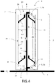
- Fig.1 shows an embodiment of the vacuum rotor system 1 according to the invention in a lateral section, which here has a hollow rotor 2 with one at both ends 2a, 2b, a first open end 2a and a second open end 2b, perpendicular to the axis of rotation R open rotor jacket surface 21 and at least two hubs 22, 23 connected to the inner side 21 i thereof within the rotor jacket surface 21, which hubs are suitably mounted in corresponding bearings 24 for the rotation of the rotor 2.
- the hub 22, which is arranged at the first open end 2a is also referred to as the first hub 22.
- the hollow rotor 2 is designed here as a cylindrical rotor with a cylindrical rotor jacket surface 21, the respective cover surfaces of the cylindrical shape being open and thus representing the open ends 2a and 2b.
- the rotor shown here is set up vertically and has an axis of rotation perpendicular to the ground.
- the first hub 22 is also used below for vertically arranged rotors lower hub 22 (closer to the ground) and the second hub 23 referred to as the upper hub 23 (further from the ground than the first and lower hubs 22, respectively).
- the rotor 2 is mounted via the hubs 22, 23 mounted separately from one another via respective separate journals 29a.
- the hubs 22, 23 are connected to one another only via the rotor jacket surface 21.
- the hubs 22, 23 could also be supported in the bearings 24 via a common shaft 29 which runs through the entire rotor 2. Bearings suitable for speeds of up to 50,000 rpm are known to those skilled in the art.
- the rotor 2 is enclosed by a machine housing 3 with at least one gas outlet opening 31 for letting gases G out of the machine housing 3, in order to ensure operational safety and operating vacuum pressure BD.
- a vacuum system 4 connected to the gas outlet opening 31 with at least one fore-pump 41 (eg rotary vane pump) for generating a fore-vacuum pressure VD in the machine housing 3 is connected.
- at least one gas extraction device 5, 51 with a gas extraction opening 53 at a suitable distance A from its inside is in the machine housing 3 between the hub 22 and the associated open end 2a of the rotor jacket surface 21, free of contact with the rotor jacket surface 21 for the effective intake of gas G. arranged and connected to the gas outlet opening 31 for discharging the absorbed gas G.
- the gas outlet opening 31 denotes the opening in the machine housing 3 through which the gas G in the machine housing 3 would have been pumped out if the gas extraction device 5, 51 were not connected to the gas outlet opening 53. With the gas extraction device 5, 51, the gas G already withdrawn by it is now transported through the gas outlet opening 31 to the outside of the machine housing 3 to the vacuum system 4.
- the gas extraction device 5, 51 is arranged in such a way that the rotor 2 at a rotational frequency greater than 200Hz itself conveys part of the gas flow G moving due to the rotor rotation along the inside 21i of the rotor jacket surface 21 at least into the first gas extraction device 5, 51 F and thus itself can reduce a gas pressure in the machine housing 3 from the fore-vacuum pressure VD to a lower operating vacuum pressure BD.
- the gas extraction device 5, 51 extends from the gas outlet opening 31, for example as an internally hollow tube, in the direction of the inside of the rotor jacket surface. Further details on the gas sampling device 5, 51 are available under Fig. 2 explained.
- Fig. 2 shows one embodiment of the vacuum rotor system 1 according to the invention according to FIG Fig.1 as an enlargement for the rotor 2 in the area of the lower hub 22.
- a gas extraction device 5 devices of different shapes and designs can be used, which provide an inner channel open for gases G between the gas extraction opening 53 and the gas outlet opening 31, 32.
- one or more gas extraction devices 5 can be connected to the same gas outlet opening 31, 32, provided that the rotor and bearing design allow an arrangement of several gas extraction devices 5 on the same side, here the side facing the open end 2a of the rotor 2 of the rotor 2 .
- a further gas extraction device 5, 51 (shown in dashed lines) is added to the one already in FIG Fig, .1
- the gas extraction device 5, 51 shown is arranged in the same plane relative to the axis of rotation R between the first (lower) hub 22 and the corresponding first open end 2a of the rotor jacket surface 21 (of the rotor 2).
- four or more gas extraction devices 5 arranged symmetrically to one another can also be arranged between the first (lower) hub 22 and the corresponding first open end 2a of the rotor jacket surface 12 (of the rotor 2).
- the material of the gas extraction device 5 consists of a material suitable for vacuum, for example stainless steel, in order to cause only little or no self-outgassing in the machine housing.
- pipe connections can be used as gas extraction devices 5, which extend in the radial direction from the gas outlet opening 53, optionally at a suitable angle, optionally deviating from 90 degrees, to the axis of rotation R towards the rotor jacket surface 21 and have a curvature before reaching the rotor jacket surface 21, so that the open tube opening as gas extraction opening 53 (as shown here for the right gas extraction opening) is aligned perpendicularly in the gas flow G along the inside 21i of the tube jacket surface 21.
- the gas flow along the inner side 21i of the rotor jacket surface 21 is shown schematically on the left side of the rotor by the two curved arrows G.
- the dashed gas extraction device 5, 51 also has a gas extraction opening 53 oriented perpendicular to the gas flow G into the gas flow G, which is not visible here due to the orientation (directed towards the rear).
- the gas extraction surface 53 denotes the surface which is oriented perpendicular to the gas flow G.
- the gas extraction opening 53 can have different shapes, for example round, oval or elliptical shapes. Shapes that are too angular can be unsuitable due to the turbulence in the gas flow G caused by them.
- the distance A between the gas intake opening 53 of the first gas extraction device 5, 51 and the rotor jacket surface 21 is here less than 10% of the radius RD of the cylindrical rotor 2 at this point. In a preferred embodiment, the distance A is between 1 and 5% of the radius RD of the rotor 2 at this point.
- the gas intake opening 53 has an effective gas intake surface 531 with a mean diameter D53 and is oriented perpendicular to the gas flow G along the rotor jacket surface 21.
- the mean diameter D53 is, for example, between 3% and 10% of the radius RD of the rotor 2.
- the first gas extraction device 5, 51 is arranged at a distance D21 from the open end of the rotor jacket surface 21, which is at least three times the mean diameter D53, thus the undisturbed gas flow can flow into the gas extraction device. If the distance D21 were shorter, at least part of the gas flow G would swirl at the edge of the rotor jacket surface 21 towards the open end 2a or flow away at the edge, which would lead to a reduction in the gas flow G flowing into the gas extraction device 5, 51. As a result, the lowest possible operating vacuum pressure could not be achieved with this arrangement.
- Fig. 3 shows another embodiment of the vacuum rotor system 1 according to the invention in a side section with an additional second gas extraction device 5, 52.
- a second gas extraction device 5, 52 is between the other hub 23 (second hub 23 or upper hub 23) than in the first gas extraction device 5, 51 and a second end 2b of the rotor jacket surface 21 corresponding to this second hub 23, arranged at a suitable distance A to the inside 21i of the rotor jacket surface 21 without contact with the rotor jacket surface 21 for additional intake of gas G.
- the hubs 22, 23 define an intermediate volume 25 between the hubs 22, 23 in the hollow cylindrical rotor 2 shown here, the second gas extraction device 5, 52 in this embodiment being arranged in such a way that the absorbed gas G is conveyed into the intermediate volume 25.
- the hubs 22, 23 are designed to be gas-impermeable to form a gas-tight intermediate volume 25, which serves as a temporary intermediate store for the gas G removed from the region of the second end of the rotor.
- a gas-tight intermediate volume 25 which serves as a temporary intermediate store for the gas G removed from the region of the second end of the rotor.
- the gas-carrying channel preferably runs between the second gas extraction device 5, 52 and the intermediate volume 25 through the upper bearing 24 and the pin 29a.
- the rotor 2 is mounted via the hubs 22, 23 mounted separately from one another via respective separate journals 29a.
- the hubs 22, 23 are connected to one another only via the rotor jacket surface 21.
- the person skilled in the art is able to suitably design the gas-carrying channel between the second gas extraction device 5, 52 and the intermediate volume 25.
- the same arrangements, orientations, distances A, distances D21 and mean diameter D53 of the gas extraction surface 53 can be selected as for the first gas extraction device 5, 51, see also Fig. 2 . This also applies to them following embodiments according to Fig. 4 + 6.
- Fig. 4 shows a further embodiment of the vacuum rotor system 1 according to the invention in a lateral section with an additional second gas extraction device 5, 52 with a direct gas connection 28 to the gas outlet opening 31 of the first gas extraction device 5, 51 as a variant of the embodiment as in FIG Fig. 3 shown.
- the second gas extraction device 5, 52 does not convey the gas G extracted from the area between the second (upper) hub 23 and the open second end 2b of the rotor 2 into the intermediate volume 25, but through this intermediate volume 25 to the first Gas outlet opening 31 for forwarding out of the machine housing 3 into the vacuum system 4.
- the direct connection 28 between the second gas extraction device 5, 52 and the gas outlet opening 31 is guided through a shaft 29 connecting the two hubs 22, 23 and to the gas channel between the first gas outlet opening 31 and connected to the vacuum system 4 in a suitable manner.
- the direct connection has a cross-section which is selected such that this direct connection 28 can be integrated into the shaft 29 of the rotor 2.
- Fig. 5 shows a further embodiment of the vacuum rotor system according to the invention according to FIG Fig. 2 and 3 as an enlargement for the rotor 2 in the area of the lower, here gas-permeable hub 22.
- a gas-absorbing layer 26 is partially arranged on the inside 25i of the intermediate volume 25. This layer 26 absorbs the gas located in the intermediate volume 25, which, for example, is released by the second gas extraction device 5, 52 according to FIG Fig. 3 is promoted in the intermediate volume. In the case of an otherwise gas-tight intermediate volume 25, this alone reduces the gas pressure in the intermediate volume 25, even with a gas-impermeable lower hub 22.
- the hub 23 facing the second gas extraction device 5, 52 is additionally gas-impermeable and the hub 22 facing the first gas extraction device 5, 51 (lower hub 22 or first hub 22) is at least partially gas-permeable, so that the gas G conveyed through the second gas extraction device 5, 52 into the intermediate volume 25 can escape through the gas-permeable hub 22 in the direction of the first gas extraction device (5, 51).
- the first gas extraction device 5, 51 can thus also discharge the gas G taken up by the second gas extraction device 5, 52 via the gas outlet opening 31 out of the machine housing 3 and into the vacuum system 4, which leads to a further decrease in the operating vacuum pressure in the machine housing 3. This also improves the pumping of the temporarily stored amount of gas at low speed.
- the gas permeability of the first (lower) hub 22 is established in this embodiment by a number of holes 27, which are preferably arranged symmetrically on the hub 22.
- Fig. 6 shows another embodiment of the vacuum rotor system 1 according to the invention in a side section with an additional second gas extraction device 5, 52 and direct connection to a second gas outlet opening 32.
- the vacuum rotor system 1 here comprises a further gas outlet opening 32 on the side of the machine housing opposite the other gas outlet opening 31 3, to which the second gas extraction device 5, 52 for discharging the gas G) it has taken in is connected to the further gas intake opening 32, which in turn is connected to the vacuum system 4.
- This direct connection allows the gas G taken up by the second gas extraction device 5, 52 to be removed from the machine housing 3 most effectively because it is the shortest route, which further reduces the operating vacuum pressure.
- Fig. 7 shows an embodiment of the method according to the invention for operating the vacuum rotor system 1 comprising the steps of generating a fore-vacuum pressure VD in the machine housing 3 with a vacuum system 4 connected to the gas outlet opening 31 with at least one forepump 41 and reducing the pressure in the machine housing 3 from the Pre-vacuum pressure VD to a lower operating vacuum pressure BD through the rotor 2 itself by means of rotation RO by inserting at least one first gas extraction device 5, 51 with a gas intake opening 53 for the effective intake of gas G in the machine housing 3 between the hub 22 and the associated open end 2a of the rotor jacket surface 21 is arranged at a suitable distance A from its inside 21i without contact with the rotor jacket surface 21 and is connected to the gas outlet opening 31 for discharging the gas G taken in, with the rotor 2 at a rotational frequency greater than 200Hz itself being part of the movement caused by the rotor rotation along the inside 21i of the rotor jacket surface 21 moving gas flow G at least into the first gas
- the embodiments shown can be achieved, for example, at an operating vacuum pressure of 10 -4 mbar at the pump connection flange G, operating vacuum pressures BD of 2 * 10 -3 mbar in the area between the upper hub 23 and the open (second) end 2b of the rotor 2.
- operating vacuum pressures BD of 2 * 10 -3 mbar in the area between the upper hub 23 and the open (second) end 2b of the rotor 2.
- turbo pumps instead of the gas extraction device according to the invention at an operating vacuum pressure of 10 -5 mbar at the pump connection flange only operating vacuum pressures of only 10 -2 mbar can be achieved on the opposite hub side, so that the vacuum rotor system 1 according to the invention is not only more cost-effective, but also comparable pressures can be achieved with better pressure distribution.
- the embodiments shown here only represent examples of the present invention and must therefore not be understood as restrictive.
Landscapes
- Engineering & Computer Science (AREA)
- General Engineering & Computer Science (AREA)
- Mechanical Engineering (AREA)
- Chemical & Material Sciences (AREA)
- Combustion & Propulsion (AREA)
- Physics & Mathematics (AREA)
- Acoustics & Sound (AREA)
- Aviation & Aerospace Engineering (AREA)
- Structures Of Non-Positive Displacement Pumps (AREA)
- Compressors, Vaccum Pumps And Other Relevant Systems (AREA)
- Applications Or Details Of Rotary Compressors (AREA)
- Non-Positive Displacement Air Blowers (AREA)
Claims (16)
- Système de rotor à vide (1) comprenant un rotor (2) de forme creuse avec une surface d'enveloppe de rotor (21) ouverte en direction des deux extrémités (2a, 2b) de manière perpendiculaire par rapport à l'axe de rotation (R) et au moins deux moyeux (22, 23) reliés à l'intérieur de la surface d'enveloppe de rotor (21) à son côté intérieur (21i), qui sont montés de manière adaptée dans des paliers (24) correspondants aux fins de la rotation du rotor (2), un carter de machine (3) entourant le rotor (2) avec au moins une ouverture de sortie de gaz (31) servant à faire sortie des gaz (G) hors du carter de machine (3), un système à vide (4) relié à l'ouverture de sortie de gaz (31) avec au moins une pompe primaire (41) servant à produire une pression de vide préliminaire (VD) dans le carter de machine (3) ainsi qu'au moins un premier dispositif de prélèvement de gaz (5, 51) disposé dans le carter de machine (3) entre le moyeu (22) et l'extrémité (2a) ouverte associée de la surface d'enveloppe de rotor (21) à une distance (A) adaptée par rapport à son côté intérieur sans contact par rapport à la surface d'enveloppe de rotor (21) pour recevoir de manière efficace du gaz (G) et relié à l'ouverture de sortie de gaz (31) aux fins de l'évacuation du gaz (G) reçu, avec une ouverture de réception de gaz (53), qui est disposée de telle sorte que le rotor (2) refoule (F) au moins dans le premier dispositif de prélèvement de gaz (5, 51) lui-même une partie du flux de gaz (G) se déplaçant du fait de la rotation de rotor le long du côté intérieur (21i) de la surface d'enveloppe de rotor (21) à une fréquence de rotation supérieure à 200 Hz et peut ainsi réduire lui-même une pression de gaz dans le carter de machine (3) de la pression de vide préliminaire (VD) sur une pression de vide de fonctionnement (BD) inférieure.
- Système de rotor à vide (1) selon la revendication 1,
caractérisé en ce
que la distance (A) entre l'ouverture de réception de gaz (53) du premier dispositif de prélèvement de gaz (5, 51) et la surface d'enveloppe de rotor (21) est inférieure à 10 % du rayon (RD) du rotor (2) à cet emplacement, de préférence la distance est comprise entre 1 et 5 % du rayon (RD) du rotor (2) à cet emplacement. - Système de rotor à vide (1) selon la revendication 1 ou 2,
caractérisé en ce
que l'ouverture de réception de gaz (53) comprend une surface de réception de gaz (531) efficace avec un diamètre (D53) moyen et est orientée de manière perpendiculaire par rapport au flux de gaz (G) le long de la surface d'enveloppe de rotor (21). - Système de rotor à vide (1) selon la revendication 3,
caractérisé en ce
que le premier dispositif de prélèvement de gaz (5, 51) est disposé à l'intérieur de la surface d'enveloppe de rotor (21) à une distance (D21) par rapport à l'extrémité ouverte de la surface d'enveloppe de rotor (21), qui est au moins le triple du diamètre (D53) moyen. - Système de rotor à vide (1) selon la revendication 3 ou 4,
caractérisé en ce
que le diamètre (D53) moyen est compris entre 3 % et 10 % du rayon (RD) du rotor (2) à cet emplacement. - Système de rotor à vide (1) selon l'une quelconque des revendications précédentes,
caractérisé en ce
que le premier dispositif de prélèvement de gaz (5, 51) possède une section transversale de manière parallèle par rapport au flux de gaz (G) le long des côtés intérieurs (21i) de la surface d'enveloppe de rotor (21), qui est adaptée pour minimiser des turbulences du flux de gaz (G) à travers le premier dispositif de prélèvement de gaz (5, 51), de préférence la section transversale est ronde ou ovale. - Système de rotor à vide (1) selon l'une quelconque des revendications précédentes,
caractérisé en ce
qu'est disposé au moins un deuxième dispositif de prélèvement de gaz (5, 52) entre le moyeu (23) autre que pour le premier dispositif de prélèvement de gaz (5, 51) et une extrémité (2b) associée, de manière correspondante par rapport audit autre moyeu (23), de la surface d'enveloppe de rotor (21) à une distance (A) adaptée par rapport au côté intérieur (21i) de la surface d'enveloppe de rotor (21) sans contact par rapport à la surface d'enveloppe de rotor (21) pour recevoir du gaz (G). - Système de rotor à vide (1) selon la revendication 7,
caractérisé en ce
que les moyeux (22, 23) définissent dans le rotor (2) de forme creuse un volume intermédiaire (25) entre les moyeux (22, 23), et le deuxième dispositif de prélèvement de gaz (5, 52) est disposé de telle sorte que le gaz (G) reçu est refoulé dans le volume intermédiaire (25). - Système de rotor à vide (1) selon la revendication 8,
caractérisé en ce
que les moyeux (22, 23) sont configurés de manière imperméable aux gaz pour former un volume intermédiaire (25) étanche aux gaz, de préférence au moins en partie une couche (26) à absorption de gaz est disposée sur le côté intérieur (25i) du volume intermédiaire (25). - Système de rotor à vide (1) selon la revendication 8,
caractérisé en ce
que le moyeu (23) tourné vers le deuxième dispositif de prélèvement de gaz (5, 52) est configuré de manière imperméable aux gaz et le moyeu (22) tourné vers le premier dispositif de prélèvement de gaz (5, 51) est configuré au moins en partie de manière perméable aux gaz si bien que le gaz (G) refoulé par le deuxième dispositif de prélèvement de gaz (5, 52) dans le volume intermédiaire (25) peut s'échapper par le moyeu (22) perméable aux gaz en direction du premier dispositif de prélèvement de gaz (5, 51). - Système de rotor à vide (1) selon la revendication 10,
caractérisé en ce
que le moyeu (22) perméable aux gaz comprend un ensemble symétrique de trous (27) servant à établir la perméabilité aux gaz. - Système de rotor à vide (1) selon la revendication 7,
caractérisé en ce
que le deuxième dispositif de prélèvement de gaz (5, 52) est relié directement à l'ouverture de sortie de gaz (31) servant à l'évacuation du gaz (G) reçu par le deuxième dispositif de prélèvement de gaz (5, 52). - Système de rotor à vide (1) selon la revendication 12,
caractérisé en ce
que la liaison (28) directe entre un deuxième dispositif de prélèvement de gaz (5, 52) et l'ouverture de sortie de gaz (31) est guidée par une tige (29) reliant les deux moyeux (22, 23). - Système de rotor à vide (1) selon la revendication 7,
caractérisé en ce
que le système de rotor à vide (1) comprend une ouverture de sortie de gaz (32) supplémentaire au niveau du côté, faisant face à l'autre ouverture de sortie de gaz (31), du carter de machine (3), le deuxième dispositif de prélèvement de gaz (5, 52) servant à l'évacuation du gaz (G) qu'il reçoit est relié à l'ouverture de réception de gaz supplémentaire (32), qui est raccordée au système à vide préliminaire (4). - Accumulateur d'énergie à volant d'inertie comprenant une multitude de systèmes de rotor à vide (1) selon la revendication 1, dans lequel le système à vide (4) d'un système de rotor à vide (1) respectif servant à produire une pression de vide préliminaire (VD) dans chaque carter de machine (3) est regroupé avec au moins une pompe à vide primaire (41) pour former un système à vide d'accumulateur d'énergie commun, qui fournit la pression de vide préliminaire (VD) dans chaque carter de machine (3).
- Procédé servant à faire fonctionner un système de rotor à vide (1) selon la revendication 1 avec un rotor (2) de forme creuse avec une surface d'enveloppe de rotor (21) ouverte en direction des deux extrémités (2a, 2b) de manière perpendiculaire par rapport à l'axe de rotation (R) et au moins deux moyeux (22, 23) reliés à l'intérieur de la surface d'enveloppe de rotor (21) à son côté intérieur (21i), qui sont montés de manière adaptée dans des paliers (24) correspondants aux fins de la rotation du rotor (2), et avec un carter de machine (3) entourant le rotor (2) avec au moins une ouverture de sortie de gaz (31) servant à faire sortir des gaz (G) hors du carter de machine (3), comprenant les étapes :- de production d'une pression de vide préliminaire (VD) dans le carter de machine (3) avec un système à vide (4) relié à l'ouverture de sortie de gaz (31) avec au moins une pompe primaire (41) ; et- de réduction de la pression dans le carter de machine (3) de la pression de vide préliminaire (VD) sur une pression de vide de fonctionnement (BD) inférieure par le rotor (2) lui-même en ce qu'au moins un premier dispositif de prélèvement de gaz (5, 51) avec une ouverture de réception de gaz (53) servant à la réception efficace de gaz (G) est disposé dans le carter de machine (3) entre le moyeu (22) et l'extrémité (2a) ouverte associée de la surface d'enveloppe de rotor (21) à une distance adaptée (A) par rapport à son côté intérieur (21i) sans contact par rapport à la surface d'enveloppe de rotor (21) et est relié à l'ouverture de sortie de gaz (31) servant à l'évacuation du gaz (G) reçu, dans lequel le rotor (2) refoule (F) au moins dans le premier dispositif de prélèvement de gaz (5, 51) lui-même une partie du flux de gaz (G) se déplaçant du fait de la rotation de rotor le long du côté intérieur (21i) de la surface d'enveloppe de rotor (21) à une fréquence de rotation supérieure à 200 Hz.
Priority Applications (6)
| Application Number | Priority Date | Filing Date | Title |
|---|---|---|---|
| EP16155415.9A EP3205884B1 (fr) | 2016-02-12 | 2016-02-12 | Système de rotor à vide auto-pompant |
| PCT/EP2017/051527 WO2017137257A1 (fr) | 2016-02-12 | 2017-01-25 | Système de rotor à vide à pompage automatique |
| AU2017217490A AU2017217490A1 (en) | 2016-02-12 | 2017-01-25 | Self-pumping vacuum rotor system |
| CA3012568A CA3012568C (fr) | 2016-02-12 | 2017-01-25 | Systeme de rotor a vide a pompage automatique |
| JP2018541384A JP6726757B2 (ja) | 2016-02-12 | 2017-01-25 | 自動ポンピング真空ロータシステム |
| US16/076,541 US11009027B2 (en) | 2016-02-12 | 2017-01-25 | Self-pumping vacuum rotor system |
Applications Claiming Priority (1)
| Application Number | Priority Date | Filing Date | Title |
|---|---|---|---|
| EP16155415.9A EP3205884B1 (fr) | 2016-02-12 | 2016-02-12 | Système de rotor à vide auto-pompant |
Publications (2)
| Publication Number | Publication Date |
|---|---|
| EP3205884A1 EP3205884A1 (fr) | 2017-08-16 |
| EP3205884B1 true EP3205884B1 (fr) | 2020-11-11 |
Family
ID=55409710
Family Applications (1)
| Application Number | Title | Priority Date | Filing Date |
|---|---|---|---|
| EP16155415.9A Active EP3205884B1 (fr) | 2016-02-12 | 2016-02-12 | Système de rotor à vide auto-pompant |
Country Status (6)
| Country | Link |
|---|---|
| US (1) | US11009027B2 (fr) |
| EP (1) | EP3205884B1 (fr) |
| JP (1) | JP6726757B2 (fr) |
| AU (1) | AU2017217490A1 (fr) |
| CA (1) | CA3012568C (fr) |
| WO (1) | WO2017137257A1 (fr) |
Families Citing this family (1)
| Publication number | Priority date | Publication date | Assignee | Title |
|---|---|---|---|---|
| US11271452B2 (en) * | 2018-11-01 | 2022-03-08 | Amber Kinetics, Inc. | Flywheel with bifurcated molecular pump |
Citations (2)
| Publication number | Priority date | Publication date | Assignee | Title |
|---|---|---|---|---|
| JPS50148973A (fr) * | 1974-05-20 | 1975-11-28 | ||
| JPS5376372U (fr) * | 1976-11-30 | 1978-06-26 |
Family Cites Families (6)
| Publication number | Priority date | Publication date | Assignee | Title |
|---|---|---|---|---|
| RU1433133C (ru) * | 1986-05-05 | 1994-03-15 | Центральное конструкторское бюро машиностроения | Черпаковый насос |
| US5462402A (en) * | 1994-02-22 | 1995-10-31 | Rosen Motors, L.P. | Flywheel energy storage system with integral molecular pump |
| DE19632375A1 (de) * | 1996-08-10 | 1998-02-19 | Pfeiffer Vacuum Gmbh | Gasreibungspumpe |
| JP2015515248A (ja) * | 2012-03-26 | 2015-05-21 | ロトニックス ホンコン リミテッド | 真空排気装置を有する電気機械式フライホイール |
| EP2698557B1 (fr) * | 2012-08-14 | 2014-10-29 | Enrichment Technology Company Ltd. | Accumulateur d'énergie à roue volante |
| DE102012110691A1 (de) * | 2012-11-08 | 2014-05-08 | Pfeiffer Vacuum Gmbh | Vorrichtung zur kinetischen Energiespeicherung |
-
2016
- 2016-02-12 EP EP16155415.9A patent/EP3205884B1/fr active Active
-
2017
- 2017-01-25 JP JP2018541384A patent/JP6726757B2/ja active Active
- 2017-01-25 WO PCT/EP2017/051527 patent/WO2017137257A1/fr not_active Ceased
- 2017-01-25 AU AU2017217490A patent/AU2017217490A1/en not_active Abandoned
- 2017-01-25 CA CA3012568A patent/CA3012568C/fr active Active
- 2017-01-25 US US16/076,541 patent/US11009027B2/en active Active
Patent Citations (2)
| Publication number | Priority date | Publication date | Assignee | Title |
|---|---|---|---|---|
| JPS50148973A (fr) * | 1974-05-20 | 1975-11-28 | ||
| JPS5376372U (fr) * | 1976-11-30 | 1978-06-26 |
Also Published As
| Publication number | Publication date |
|---|---|
| US20190055948A1 (en) | 2019-02-21 |
| WO2017137257A1 (fr) | 2017-08-17 |
| US11009027B2 (en) | 2021-05-18 |
| EP3205884A1 (fr) | 2017-08-16 |
| CA3012568A1 (fr) | 2017-08-17 |
| AU2017217490A1 (en) | 2018-08-16 |
| CA3012568C (fr) | 2020-10-27 |
| JP2019507276A (ja) | 2019-03-14 |
| JP6726757B2 (ja) | 2020-07-22 |
Similar Documents
| Publication | Publication Date | Title |
|---|---|---|
| EP3550150B1 (fr) | Procédé d'equilibrage d'un rotor d'une pompe à vide ou d'un rotor d'une unité de rotation pour une pompe à vide | |
| EP2209995B1 (fr) | Rotor de pompe à plusieurs étages pour pompes turbomoléculaires | |
| EP2730782B1 (fr) | Dispositif de stockage d'énergie cinétique | |
| DE102008021683A1 (de) | Rotierende Einheit für einen Axialkompressor | |
| EP4041994A1 (fr) | Turbomachine etprocédé de fonctionnement d'une turbomachine | |
| EP0363503B1 (fr) | Etage de pompage pour une pompe à vide élevé | |
| DE4339060A1 (de) | Getriebeverdichter für die Verdichtung von Sauerstoff | |
| EP1483506A1 (fr) | Pompe turbomoleculaire a surface d'aspiration circulaire cote vide pousse | |
| EP1067290A2 (fr) | Pompe à vide | |
| DE3321718A1 (de) | Waelzkolbenpumpe | |
| EP3088743B1 (fr) | Étage de pompe a vide à canal latéral avec un barrage de canal qui présente une rampe du côté de l'aspiration | |
| EP3205884A1 (fr) | Système de rotor à vide auto-pompant | |
| DE1628271C3 (de) | Mehrstufiger Flüssigkeitsringverdichter bzw. mehrstufige Flüssigkeitsringpumpe | |
| DE10224604B4 (de) | Evakuierungseinrichtung | |
| DE3826710C2 (fr) | ||
| DE2409857A1 (de) | Turbomolekularvakuumpumpe mit zumindest teilweise glockenfoermig ausgebildetem rotor | |
| AT512657A4 (de) | Schwungrad | |
| EP1626179B1 (fr) | Pompe à vide | |
| DE102015113821B4 (de) | Vakuumpumpe | |
| DE102014112553A1 (de) | Vakuumpumpe | |
| DE10296120B4 (de) | Radialverdichter für Beatmungsgeräte | |
| DE19714549C2 (de) | Vakuumgehäuse für ein Schwungrad für hohe Drehzahlen | |
| EP3575610A1 (fr) | Pompe à vide avec réservoir de lubrifiant | |
| EP2713084B1 (fr) | Système de fermeture de sécurité sous vide | |
| EP2492495A2 (fr) | Dispositif de conversion d'énergie |
Legal Events
| Date | Code | Title | Description |
|---|---|---|---|
| PUAI | Public reference made under article 153(3) epc to a published international application that has entered the european phase |
Free format text: ORIGINAL CODE: 0009012 |
|
| STAA | Information on the status of an ep patent application or granted ep patent |
Free format text: STATUS: THE APPLICATION HAS BEEN PUBLISHED |
|
| AK | Designated contracting states |
Kind code of ref document: A1 Designated state(s): AL AT BE BG CH CY CZ DE DK EE ES FI FR GB GR HR HU IE IS IT LI LT LU LV MC MK MT NL NO PL PT RO RS SE SI SK SM TR |
|
| AX | Request for extension of the european patent |
Extension state: BA ME |
|
| STAA | Information on the status of an ep patent application or granted ep patent |
Free format text: STATUS: REQUEST FOR EXAMINATION WAS MADE |
|
| 17P | Request for examination filed |
Effective date: 20180216 |
|
| RBV | Designated contracting states (corrected) |
Designated state(s): AL AT BE BG CH CY CZ DE DK EE ES FI FR GB GR HR HU IE IS IT LI LT LU LV MC MK MT NL NO PL PT RO RS SE SI SK SM TR |
|
| GRAP | Despatch of communication of intention to grant a patent |
Free format text: ORIGINAL CODE: EPIDOSNIGR1 |
|
| STAA | Information on the status of an ep patent application or granted ep patent |
Free format text: STATUS: GRANT OF PATENT IS INTENDED |
|
| RIC1 | Information provided on ipc code assigned before grant |
Ipc: F03G 3/08 20060101ALI20200511BHEP Ipc: F04D 1/12 20060101ALI20200511BHEP Ipc: F04D 17/16 20060101AFI20200511BHEP |
|
| INTG | Intention to grant announced |
Effective date: 20200528 |
|
| GRAS | Grant fee paid |
Free format text: ORIGINAL CODE: EPIDOSNIGR3 |
|
| GRAA | (expected) grant |
Free format text: ORIGINAL CODE: 0009210 |
|
| STAA | Information on the status of an ep patent application or granted ep patent |
Free format text: STATUS: THE PATENT HAS BEEN GRANTED |
|
| AK | Designated contracting states |
Kind code of ref document: B1 Designated state(s): AL AT BE BG CH CY CZ DE DK EE ES FI FR GB GR HR HU IE IS IT LI LT LU LV MC MK MT NL NO PL PT RO RS SE SI SK SM TR |
|
| REG | Reference to a national code |
Ref country code: GB Ref legal event code: FG4D Free format text: NOT ENGLISH |
|
| REG | Reference to a national code |
Ref country code: CH Ref legal event code: EP |
|
| REG | Reference to a national code |
Ref country code: AT Ref legal event code: REF Ref document number: 1333733 Country of ref document: AT Kind code of ref document: T Effective date: 20201115 |
|
| REG | Reference to a national code |
Ref country code: DE Ref legal event code: R096 Ref document number: 502016011647 Country of ref document: DE |
|
| REG | Reference to a national code |
Ref country code: IE Ref legal event code: FG4D Free format text: LANGUAGE OF EP DOCUMENT: GERMAN |
|
| REG | Reference to a national code |
Ref country code: CH Ref legal event code: NV Representative=s name: TR-IP CONSULTING LLC, CH |
|
| REG | Reference to a national code |
Ref country code: NL Ref legal event code: FP |
|
| PG25 | Lapsed in a contracting state [announced via postgrant information from national office to epo] |
Ref country code: GR Free format text: LAPSE BECAUSE OF FAILURE TO SUBMIT A TRANSLATION OF THE DESCRIPTION OR TO PAY THE FEE WITHIN THE PRESCRIBED TIME-LIMIT Effective date: 20210212 Ref country code: RS Free format text: LAPSE BECAUSE OF FAILURE TO SUBMIT A TRANSLATION OF THE DESCRIPTION OR TO PAY THE FEE WITHIN THE PRESCRIBED TIME-LIMIT Effective date: 20201111 Ref country code: PT Free format text: LAPSE BECAUSE OF FAILURE TO SUBMIT A TRANSLATION OF THE DESCRIPTION OR TO PAY THE FEE WITHIN THE PRESCRIBED TIME-LIMIT Effective date: 20210311 Ref country code: FI Free format text: LAPSE BECAUSE OF FAILURE TO SUBMIT A TRANSLATION OF THE DESCRIPTION OR TO PAY THE FEE WITHIN THE PRESCRIBED TIME-LIMIT Effective date: 20201111 Ref country code: NO Free format text: LAPSE BECAUSE OF FAILURE TO SUBMIT A TRANSLATION OF THE DESCRIPTION OR TO PAY THE FEE WITHIN THE PRESCRIBED TIME-LIMIT Effective date: 20210211 |
|
| PG25 | Lapsed in a contracting state [announced via postgrant information from national office to epo] |
Ref country code: IS Free format text: LAPSE BECAUSE OF FAILURE TO SUBMIT A TRANSLATION OF THE DESCRIPTION OR TO PAY THE FEE WITHIN THE PRESCRIBED TIME-LIMIT Effective date: 20210311 Ref country code: SE Free format text: LAPSE BECAUSE OF FAILURE TO SUBMIT A TRANSLATION OF THE DESCRIPTION OR TO PAY THE FEE WITHIN THE PRESCRIBED TIME-LIMIT Effective date: 20201111 Ref country code: PL Free format text: LAPSE BECAUSE OF FAILURE TO SUBMIT A TRANSLATION OF THE DESCRIPTION OR TO PAY THE FEE WITHIN THE PRESCRIBED TIME-LIMIT Effective date: 20201111 Ref country code: LV Free format text: LAPSE BECAUSE OF FAILURE TO SUBMIT A TRANSLATION OF THE DESCRIPTION OR TO PAY THE FEE WITHIN THE PRESCRIBED TIME-LIMIT Effective date: 20201111 Ref country code: BG Free format text: LAPSE BECAUSE OF FAILURE TO SUBMIT A TRANSLATION OF THE DESCRIPTION OR TO PAY THE FEE WITHIN THE PRESCRIBED TIME-LIMIT Effective date: 20210211 |
|
| REG | Reference to a national code |
Ref country code: LT Ref legal event code: MG9D |
|
| PG25 | Lapsed in a contracting state [announced via postgrant information from national office to epo] |
Ref country code: HR Free format text: LAPSE BECAUSE OF FAILURE TO SUBMIT A TRANSLATION OF THE DESCRIPTION OR TO PAY THE FEE WITHIN THE PRESCRIBED TIME-LIMIT Effective date: 20201111 |
|
| PG25 | Lapsed in a contracting state [announced via postgrant information from national office to epo] |
Ref country code: SM Free format text: LAPSE BECAUSE OF FAILURE TO SUBMIT A TRANSLATION OF THE DESCRIPTION OR TO PAY THE FEE WITHIN THE PRESCRIBED TIME-LIMIT Effective date: 20201111 Ref country code: LT Free format text: LAPSE BECAUSE OF FAILURE TO SUBMIT A TRANSLATION OF THE DESCRIPTION OR TO PAY THE FEE WITHIN THE PRESCRIBED TIME-LIMIT Effective date: 20201111 Ref country code: EE Free format text: LAPSE BECAUSE OF FAILURE TO SUBMIT A TRANSLATION OF THE DESCRIPTION OR TO PAY THE FEE WITHIN THE PRESCRIBED TIME-LIMIT Effective date: 20201111 Ref country code: CZ Free format text: LAPSE BECAUSE OF FAILURE TO SUBMIT A TRANSLATION OF THE DESCRIPTION OR TO PAY THE FEE WITHIN THE PRESCRIBED TIME-LIMIT Effective date: 20201111 Ref country code: RO Free format text: LAPSE BECAUSE OF FAILURE TO SUBMIT A TRANSLATION OF THE DESCRIPTION OR TO PAY THE FEE WITHIN THE PRESCRIBED TIME-LIMIT Effective date: 20201111 Ref country code: SK Free format text: LAPSE BECAUSE OF FAILURE TO SUBMIT A TRANSLATION OF THE DESCRIPTION OR TO PAY THE FEE WITHIN THE PRESCRIBED TIME-LIMIT Effective date: 20201111 |
|
| REG | Reference to a national code |
Ref country code: DE Ref legal event code: R097 Ref document number: 502016011647 Country of ref document: DE |
|
| PG25 | Lapsed in a contracting state [announced via postgrant information from national office to epo] |
Ref country code: DK Free format text: LAPSE BECAUSE OF FAILURE TO SUBMIT A TRANSLATION OF THE DESCRIPTION OR TO PAY THE FEE WITHIN THE PRESCRIBED TIME-LIMIT Effective date: 20201111 |
|
| PLBE | No opposition filed within time limit |
Free format text: ORIGINAL CODE: 0009261 |
|
| STAA | Information on the status of an ep patent application or granted ep patent |
Free format text: STATUS: NO OPPOSITION FILED WITHIN TIME LIMIT |
|
| PG25 | Lapsed in a contracting state [announced via postgrant information from national office to epo] |
Ref country code: MC Free format text: LAPSE BECAUSE OF FAILURE TO SUBMIT A TRANSLATION OF THE DESCRIPTION OR TO PAY THE FEE WITHIN THE PRESCRIBED TIME-LIMIT Effective date: 20201111 |
|
| 26N | No opposition filed |
Effective date: 20210812 |
|
| REG | Reference to a national code |
Ref country code: BE Ref legal event code: MM Effective date: 20210228 |
|
| PG25 | Lapsed in a contracting state [announced via postgrant information from national office to epo] |
Ref country code: LU Free format text: LAPSE BECAUSE OF NON-PAYMENT OF DUE FEES Effective date: 20210212 Ref country code: AL Free format text: LAPSE BECAUSE OF FAILURE TO SUBMIT A TRANSLATION OF THE DESCRIPTION OR TO PAY THE FEE WITHIN THE PRESCRIBED TIME-LIMIT Effective date: 20201111 |
|
| PG25 | Lapsed in a contracting state [announced via postgrant information from national office to epo] |
Ref country code: SI Free format text: LAPSE BECAUSE OF FAILURE TO SUBMIT A TRANSLATION OF THE DESCRIPTION OR TO PAY THE FEE WITHIN THE PRESCRIBED TIME-LIMIT Effective date: 20201111 |
|
| PG25 | Lapsed in a contracting state [announced via postgrant information from national office to epo] |
Ref country code: ES Free format text: LAPSE BECAUSE OF FAILURE TO SUBMIT A TRANSLATION OF THE DESCRIPTION OR TO PAY THE FEE WITHIN THE PRESCRIBED TIME-LIMIT Effective date: 20201111 |
|
| PG25 | Lapsed in a contracting state [announced via postgrant information from national office to epo] |
Ref country code: IS Free format text: LAPSE BECAUSE OF FAILURE TO SUBMIT A TRANSLATION OF THE DESCRIPTION OR TO PAY THE FEE WITHIN THE PRESCRIBED TIME-LIMIT Effective date: 20210311 |
|
| REG | Reference to a national code |
Ref country code: DE Ref legal event code: R082 Ref document number: 502016011647 Country of ref document: DE Representative=s name: FARAGO PATENTANWAELTE GMBH, DE Ref country code: DE Ref legal event code: R082 Ref document number: 502016011647 Country of ref document: DE Representative=s name: FARAGO PATENTANWALTSGESELLSCHAFT MBH, DE |
|
| PG25 | Lapsed in a contracting state [announced via postgrant information from national office to epo] |
Ref country code: BE Free format text: LAPSE BECAUSE OF NON-PAYMENT OF DUE FEES Effective date: 20210228 |
|
| PG25 | Lapsed in a contracting state [announced via postgrant information from national office to epo] |
Ref country code: HU Free format text: LAPSE BECAUSE OF FAILURE TO SUBMIT A TRANSLATION OF THE DESCRIPTION OR TO PAY THE FEE WITHIN THE PRESCRIBED TIME-LIMIT; INVALID AB INITIO Effective date: 20160212 |
|
| PG25 | Lapsed in a contracting state [announced via postgrant information from national office to epo] |
Ref country code: CY Free format text: LAPSE BECAUSE OF FAILURE TO SUBMIT A TRANSLATION OF THE DESCRIPTION OR TO PAY THE FEE WITHIN THE PRESCRIBED TIME-LIMIT Effective date: 20201111 |
|
| PG25 | Lapsed in a contracting state [announced via postgrant information from national office to epo] |
Ref country code: MK Free format text: LAPSE BECAUSE OF FAILURE TO SUBMIT A TRANSLATION OF THE DESCRIPTION OR TO PAY THE FEE WITHIN THE PRESCRIBED TIME-LIMIT Effective date: 20201111 |
|
| PG25 | Lapsed in a contracting state [announced via postgrant information from national office to epo] |
Ref country code: MT Free format text: LAPSE BECAUSE OF FAILURE TO SUBMIT A TRANSLATION OF THE DESCRIPTION OR TO PAY THE FEE WITHIN THE PRESCRIBED TIME-LIMIT Effective date: 20201111 |
|
| PG25 | Lapsed in a contracting state [announced via postgrant information from national office to epo] |
Ref country code: TR Free format text: LAPSE BECAUSE OF FAILURE TO SUBMIT A TRANSLATION OF THE DESCRIPTION OR TO PAY THE FEE WITHIN THE PRESCRIBED TIME-LIMIT Effective date: 20201111 |
|
| REG | Reference to a national code |
Ref country code: CH Ref legal event code: U11 Free format text: ST27 STATUS EVENT CODE: U-0-0-U10-U11 (AS PROVIDED BY THE NATIONAL OFFICE) Effective date: 20260301 |
|
| PGFP | Annual fee paid to national office [announced via postgrant information from national office to epo] |
Ref country code: NL Payment date: 20260218 Year of fee payment: 11 |
|
| PGFP | Annual fee paid to national office [announced via postgrant information from national office to epo] |
Ref country code: GB Payment date: 20260219 Year of fee payment: 11 |
|
| PGFP | Annual fee paid to national office [announced via postgrant information from national office to epo] |
Ref country code: IE Payment date: 20260218 Year of fee payment: 11 Ref country code: DE Payment date: 20260224 Year of fee payment: 11 |
|
| PGFP | Annual fee paid to national office [announced via postgrant information from national office to epo] |
Ref country code: AT Payment date: 20260219 Year of fee payment: 11 |
|
| PGFP | Annual fee paid to national office [announced via postgrant information from national office to epo] |
Ref country code: IT Payment date: 20260224 Year of fee payment: 11 |
|
| PGFP | Annual fee paid to national office [announced via postgrant information from national office to epo] |
Ref country code: FR Payment date: 20260218 Year of fee payment: 11 |
|
| PGFP | Annual fee paid to national office [announced via postgrant information from national office to epo] |
Ref country code: CH Payment date: 20260301 Year of fee payment: 11 |