EP3205906A1 - Système de commande électronique pour une transmission automatique d'automobile - Google Patents
Système de commande électronique pour une transmission automatique d'automobile Download PDFInfo
- Publication number
- EP3205906A1 EP3205906A1 EP16155116.3A EP16155116A EP3205906A1 EP 3205906 A1 EP3205906 A1 EP 3205906A1 EP 16155116 A EP16155116 A EP 16155116A EP 3205906 A1 EP3205906 A1 EP 3205906A1
- Authority
- EP
- European Patent Office
- Prior art keywords
- mode
- transmission
- selector
- switch
- electronic control
- Prior art date
- Legal status (The legal status is an assumption and is not a legal conclusion. Google has not performed a legal analysis and makes no representation as to the accuracy of the status listed.)
- Granted
Links
Images

Classifications
-
- F—MECHANICAL ENGINEERING; LIGHTING; HEATING; WEAPONS; BLASTING
- F16—ENGINEERING ELEMENTS AND UNITS; GENERAL MEASURES FOR PRODUCING AND MAINTAINING EFFECTIVE FUNCTIONING OF MACHINES OR INSTALLATIONS; THERMAL INSULATION IN GENERAL
- F16H—GEARING
- F16H59/00—Control inputs to control units of change-speed- or reversing-gearings for conveying rotary motion
- F16H59/02—Selector apparatus
- F16H59/0278—Constructional features of the selector lever, e.g. grip parts, mounting or manufacturing
-
- F—MECHANICAL ENGINEERING; LIGHTING; HEATING; WEAPONS; BLASTING
- F16—ENGINEERING ELEMENTS AND UNITS; GENERAL MEASURES FOR PRODUCING AND MAINTAINING EFFECTIVE FUNCTIONING OF MACHINES OR INSTALLATIONS; THERMAL INSULATION IN GENERAL
- F16H—GEARING
- F16H59/00—Control inputs to control units of change-speed- or reversing-gearings for conveying rotary motion
- F16H59/02—Selector apparatus
- F16H59/0204—Selector apparatus for automatic transmissions with means for range selection and manual shifting, e.g. range selector with tiptronic
-
- F—MECHANICAL ENGINEERING; LIGHTING; HEATING; WEAPONS; BLASTING
- F16—ENGINEERING ELEMENTS AND UNITS; GENERAL MEASURES FOR PRODUCING AND MAINTAINING EFFECTIVE FUNCTIONING OF MACHINES OR INSTALLATIONS; THERMAL INSULATION IN GENERAL
- F16H—GEARING
- F16H59/00—Control inputs to control units of change-speed- or reversing-gearings for conveying rotary motion
- F16H59/02—Selector apparatus
- F16H59/08—Range selector apparatus
-
- F—MECHANICAL ENGINEERING; LIGHTING; HEATING; WEAPONS; BLASTING
- F16—ENGINEERING ELEMENTS AND UNITS; GENERAL MEASURES FOR PRODUCING AND MAINTAINING EFFECTIVE FUNCTIONING OF MACHINES OR INSTALLATIONS; THERMAL INSULATION IN GENERAL
- F16H—GEARING
- F16H59/00—Control inputs to control units of change-speed- or reversing-gearings for conveying rotary motion
- F16H59/02—Selector apparatus
- F16H59/08—Range selector apparatus
- F16H59/10—Range selector apparatus comprising levers
- F16H59/105—Range selector apparatus comprising levers consisting of electrical switches or sensors
-
- F—MECHANICAL ENGINEERING; LIGHTING; HEATING; WEAPONS; BLASTING
- F16—ENGINEERING ELEMENTS AND UNITS; GENERAL MEASURES FOR PRODUCING AND MAINTAINING EFFECTIVE FUNCTIONING OF MACHINES OR INSTALLATIONS; THERMAL INSULATION IN GENERAL
- F16H—GEARING
- F16H59/00—Control inputs to control units of change-speed- or reversing-gearings for conveying rotary motion
- F16H59/02—Selector apparatus
- F16H59/0278—Constructional features of the selector lever, e.g. grip parts, mounting or manufacturing
- F16H2059/0282—Lever handles with lock mechanisms, e.g. for allowing selection of reverse gear or releasing lever from park position
-
- F—MECHANICAL ENGINEERING; LIGHTING; HEATING; WEAPONS; BLASTING
- F16—ENGINEERING ELEMENTS AND UNITS; GENERAL MEASURES FOR PRODUCING AND MAINTAINING EFFECTIVE FUNCTIONING OF MACHINES OR INSTALLATIONS; THERMAL INSULATION IN GENERAL
- F16H—GEARING
- F16H59/00—Control inputs to control units of change-speed- or reversing-gearings for conveying rotary motion
- F16H59/02—Selector apparatus
- F16H59/08—Range selector apparatus
- F16H2059/081—Range selector apparatus using knops or discs for rotary range selection
-
- F—MECHANICAL ENGINEERING; LIGHTING; HEATING; WEAPONS; BLASTING
- F16—ENGINEERING ELEMENTS AND UNITS; GENERAL MEASURES FOR PRODUCING AND MAINTAINING EFFECTIVE FUNCTIONING OF MACHINES OR INSTALLATIONS; THERMAL INSULATION IN GENERAL
- F16H—GEARING
- F16H59/00—Control inputs to control units of change-speed- or reversing-gearings for conveying rotary motion
- F16H59/02—Selector apparatus
- F16H59/08—Range selector apparatus
- F16H2059/082—Range selector apparatus for different transmission modes
- F16H2059/088—Fast forward-reverse-sequence, e.g. rocking mode
Definitions
- the present invention relates to an automotive electronic control system for an automotive automatic transmission.
- the role of cognitive ergonomics in the automotive field is designing automotive onboard system interfaces capable of reducing the cognitive load on drivers whilst driving.
- the object of the present invention is providing a solution that improves simplicity, naturalness and intuitiveness of automotive automatic transmissions controls.
- an automotive electronic system for an automotive automatic transmission is provided, as claimed in the appended claims.
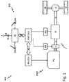
- Figure 1 shows, by way of non-limitative example, a block diagram of an automotive electronic control system ECS of a power train of a motor vehicle MV.
- the power train PWT comprises a power unit PU that can alternatively be a single or bi-fuel internal combustion engine, an electric motor or a hybrid engine, the output shaft CS of which is connected to a power-assisted transmission T that can indifferently be of the single-clutch type, as shown in Figure 1 , or of the dual-clutch type (not shown).
- the transmission T comprises a gearbox G with discrete or continuously variable ratios, with an input shaft I that can be coupled to the output shaft CS of the power unit PU through a single coupling or clutch C external to the gearbox G, and an output shaft 0 connected to a pair of drive wheels W via a differential D of known type.
- the clutch C is servo-controlled by an associated electrically or hydraulically controlled actuator CA that can be operated to disengage and engage the clutch C in response to an electrical command.
- the gearbox G is also servo-controlled by a plurality of electrically or hydraulically controlled actuators, indicated as a whole by reference GA, which can be operated to engage and disengage the gears corresponding to the different speed ratios available.
- the transmission T comprises two distinct clutches (not shown), one associated with the even speed ratios and the other associated with the odd speed ratios, integrated inside the gearbox G.
- the electronic control system ECS comprises an electronic control unit PU-ECU dedicated to controlling the power unit PU, and an electronic control unit PWT-ECU dedicated to controlling the power train PWT, which is connected to the PU-ECU electronic control unit via an automotive onboard communication network NET, for example CAN, FlexRay or others, as well as to the actuators CA and GA associated with the clutch C and gearbox G.
- NET automotive onboard communication network
- the PU-ECU electronic control unit and the PWT-ECU electronic control unit are integrated into a single electronic control unit PWT-ECU that performs the functions of both the PU-ECU and PWT-ECU electronic control units.
- the electronic control system ECS also comprises a body computer BC connected to the electronic control unit PWT-ECU via the onboard communications network NET and programmed to receive quantities indicative of the operating conditions of systems/components on board the motor vehicle MV, such as the power train PWT, battery/batteries, accelerator pedal AP, brake pedal BP, handbrake, etc., and to manage the operation of the power train PWT in consequence.
- a body computer BC connected to the electronic control unit PWT-ECU via the onboard communications network NET and programmed to receive quantities indicative of the operating conditions of systems/components on board the motor vehicle MV, such as the power train PWT, battery/batteries, accelerator pedal AP, brake pedal BP, handbrake, etc., and to manage the operation of the power train PWT in consequence.
- the body computer BC and the electronic control units PU-ECU and PWT-ECU are programmed to store and execute control software for the power train PWT, which will be described in detail hereinafter.
- the power train PWT functions in response to electrical commands generated by the electronic control units PU-ECU and PWT-ECU on the basis of commands given by the driver through a series of hand-operated or foot-operated devices connected to the body computer BC and comprising, among others, an accelerator pedal AP, a brake pedal BP and one or more hand-operated controls for controlling the transmission T and comprising a selector SL of an operating mode of the transmission T, a pair of paddles P for sequentially changing the forward speed gears, and a pushbutton or rocker or knob selector S of programs for automatically changing forward speed gears.
- a series of hand-operated or foot-operated devices connected to the body computer BC and comprising, among others, an accelerator pedal AP, a brake pedal BP and one or more hand-operated controls for controlling the transmission T and comprising a selector SL of an operating mode of the transmission T, a pair of paddles P for sequentially changing the forward speed gears, and a pushbutton or rocker or knob select
- the selector SL can be operated to select one of a plurality of modes or operating conditions of the transmission T, comprising a reverse mode R, a neutral mode N, a drive mode D for automatically changing the forward speed gears and a manual step-by-step mode (M) for sequentially changing the forward speed gears by hand.
- the selector SL is of the monostable type, i.e. it is designed to assume, when not operated, a stable central neutral position, and to be moved by hand in first selection or operation directions from the stable central neutral position to reach two unstable or momentary end-of-travel positions arranged on opposite sides of the stable central neutral position, where the term 'momentary' is intended to indicate positions that the selector SL is capable of assuming and maintaining only as long as the driver's hand operation lasts and from which it autonomously returns to the stable central neutral position when the driver's hand operation ceases, and where the term 'end-of-travel' is intended to indicate positions that define the stop positions beyond which the selector cannot go, i.e. at which it stops without being able to continue further, or rather without being able to perform overtravel to further end-of-travel positions in response to the exertion of forces such as to allow it go beyond the end-of-travel positions.
- Figure 2 shows the diagram of the shift pattern of the selection lever and the operating modes of the transmission T associated with the shift pattern positions, as shall be described in detail hereinafter, and where the solid circular symbol represents the stable central neutral position and the two empty circular symbols represent the momentary selection positions.
- the selector SL can also be designed to be further movable by hand from the stable central neutral position in second directions of selection or operation, transversal to the first directions of selection or operation, to reach one or more end-of-travel positions, which can be alternatively stable or momentary, but are also conveniently momentary.
- the selector SL is equipped with a momentary pushbutton park switch P for selecting a park mode P, and a momentary pushbutton control switch B.
- the park mode P may be selected via the selection lever SL.
- the selector SL is also appropriately sensorized to detect operation of the selector SL in the two opposite selection directions and reaching the momentary selection positions, as well as operation (pressing and releasing) of the park and control pushbutton switches P, B.
- the selector SL is in the form of a selection lever conveniently arranged at the tunnel console arranged in the central tunnel of the motor vehicle, between the driver and passenger front seats, and terminating at the front in the so-called centre console.
- the selection lever SL is mounted to be manually tippable longitudinally forwards and backwards from a substantially vertical stable central neutral position to reach the forward and backward momentary selection positions, respectively.
- the selection lever SL thus performs an oscillatory movement about a fulcrum along a curvilinear path.
- the selection lever SL is mounted to be manually displaceable longitudinally forwards and backwards from the substantially vertical stable central neutral position, but always to reach the forward and backward momentary selection positions, respectively. In this embodiment, the selection lever SL therefore performs a translational movement along a rectilinear path.
- the selection lever SL can be mounted to be also tippable or translatable transversely to the left and to the right from the stable central neutral position to reach one or more further lateral selection positions, which are conveniently, but not necessarily, momentary positions.
- the reverse mode R, neutral mode N, and drive mode D are selectable by operating the selection lever SL in the forward and backward selection directions
- the manual step-by-step mode M is selectable by operating the selection lever SL in a transverse selection direction, to the left in the example shown, to reach a position, which can be alternatively stable or momentary, but is conveniently momentary.
- subsequent operations of the selection lever SL in the forward and backward selection directions cause changing up or down of the forward speed gears.
- the park switch P is conveniently arranged on the top of the selection lever SL in such a way that when the lever is gripped the pushbutton park switch P is thumb-operable, while the control switch B is conveniently arranged on a frontal area of the selection lever SL so that it can be operated by one or more of the index, middle, ring and little fingers. It goes without saying that the positions indicated for the control and park pushbuttons could be different from those indicated.
- the selection lever SL is arranged behind the steering wheel of the motor vehicle MV and mounted on the so-called steering column switch, which, as is known, is a device located behind the steering wheel and equipped with a series of levers through which the driver can control the operation of a series of onboard devices such as direction indicators, front and rear wipers, front and rear lights, etc.
- the selection lever SL is mounted to be manually tippable upwards and downwards from a substantially horizontal stable central neutral position to reach raised and lowered momentary selection positions, respectively.
- the selection lever SL performs an oscillatory movement about a fulcrum along a substantially curvilinear path.
- the park switch P and the control switch B are conveniently arranged on a free end of the selection lever SL, one on the tip face and the other on the top part of the lateral surface, so that one can be operated with the thumb and the other with one or more fingers of the hand.
- the selector SL is of a rotational rocking type and has the shape of a knob, conveniently mountable on the tunnel console with a vertical axis of rotation so as to be manually rotatable in a rocking manner to the left and to the right from the stable central neutral position, to reach the left and right momentary selection positions, respectively.
- the knob performs a rotary movement with respect to a fulcrum along a substantially circular path.
- the knob may be mounted on the tunnel console with a transversal horizontal axis of rotation so as to be manually rotatable in a forwards and backwards rocking manner like the selection lever SL. It goes without saying that other arrangements of the knob are possible.
- the park switch P and the control switch B are conveniently arranged at the centre of the knob and at the side of the knob, respectively.
- the paddles for sequentially changing gears are coupled to the steering wheel so as to be rotationally integral with it and can be operated manually by the driver for sequentially changing up and down the forward speed gears in the manual step-by-step mode and, possibly, through specific operations, to implement further gear change functions, for example to implement specific gear change programs.
- the manual sequential changing of the forward speed gears may be implemented via dedicated pushbuttons located on the steering wheel.
- the manual sequential changing of the speed gears may be implemented via the selection lever SL.
- the pushbutton or rocker selector for programs for automatically changing the forward speed gears can be located on the steering wheel or on the tunnel console, close to the selection lever SL, or in the central area of the dashboard and be hand operated to select one of a plurality of programs for automatically changing the forward speed gears, typically comprising a sports program and a fuel saving program, and possibly for making further selections, for example passing from manual step-by-step mode to drive mode and vice versa.
- the selection of programs for automatically changing the forward speed gears can be implemented through the selection lever SL, appropriately operated.
- the control software of the power train PWT is designed to determine, on the basis of electrical signals supplied by the sensor system of the selector SL, the operation of the selector SL and of the parking P and control B pushbutton switches, in particular the reaching of the momentary selection positions following taps given by the driver's hand to the selector SL, forwards and backwards in the above-described first embodiment, or up and down in the above-described second embodiment, or to the left and to the right in the above-described third embodiment, and the pressing and releasing of the parking P and control B pushbutton switches.
- control software is designed to implement, with the motor vehicle MV stationary, the passages between the various operating modes of the transmission T indicated in Table I below according to the selection directions (forward/up/left and backward/down/right) in which the selector SL is moved and based on the operating state (pressed/released) of the pushbutton control switch B.
- Table I Motor Vehicle Stationary Selected Mode SL: Fwd/Up/Left SL: Fwd/Up/Left SL: Back/Down/Right SL: Back/Down/Right B: Released B: Pressed B: Released B: Pressed B: Released B: Pressed B: Pressed B: Pressed B: Pressed P - N - D R - - N D N - R D D D N R - - -
- control software is designed to:
- control software enables performing:
- the present invention enables implementing in a simple and intuitive manner the so-called forward and backward rocking function of the motor vehicle MV, useful for getting free when stuck in mud or similar.
- control software is designed to implement, always with the motor vehicle stationary, the passages between the various operating modes of the transmission T indicated in Table II below according to the selection directions in which the selector SL is moved and based on the operating state of the control switch B.
- Table II Motor Vehicle Stationary Selected Mode SL: Fwd/Up/Left SL: Fwd/Up/Left SL: Back/Down/Right SL: Back/Down/Right B: Released B: Pressed B: Released B: Pressed B: Released B: Pressed B: Pressed P N / - R - D R - - N P N - R D D D N P - - -
- this embodiment differs from that previously described with reference to Table I in that when the transmission T is in park mode P, the control software causes, in response to a forward/up/left operation of the selector SL with the control switch B pressed, switch to reverse mode R rather than to neutral mode N, as instead happens in the previous embodiment, while in response to a forward/up/left operation of the selector SL with the control switch B released, it causes the transmission T either to switch to neutral mode N or to remain in park mode P, depending on the market (EMEA, APAC, or NAFTA) to which the motor vehicle MV is destined.
- EMEA EMEA, APAC, or NAFTA
- control software enables direct passage from park mode P to reverse mode R, by keeping the pushbutton control switch B pressed during operation of the selector SL.
- the control software is designed to implement in the reverse mode R, neutral mode N and drive mode D, the same switches of operating mode of the transmission T in response to operation of the selector SL and the control switch B as those contemplated with the motor vehicle MV stationary, with the further feature that these switched are only allowed when the motor vehicle MV is travelling in a direction consistent with the selected operating mode of the transmission T, i.e. backwards for reverse mode R and forwards for drive mode D, and at any speed, or in the opposite direction, i.e. forwards for the reverse mode R and backwards for the drive mode D, but at very low speed, i.e. below a given speed threshold, for example 6 km/h.
- the operation of the selector SL is ignored.
Landscapes
- Engineering & Computer Science (AREA)
- General Engineering & Computer Science (AREA)
- Mechanical Engineering (AREA)
- Arrangement Or Mounting Of Control Devices For Change-Speed Gearing (AREA)
- Control Of Transmission Device (AREA)
Priority Applications (2)
| Application Number | Priority Date | Filing Date | Title |
|---|---|---|---|
| EP16155116.3A EP3205906B1 (fr) | 2016-02-10 | 2016-02-10 | Système de commande électronique pour une transmission automatique d'automobile |
| US15/428,690 US10436309B2 (en) | 2016-02-10 | 2017-02-09 | Electronic control system for an automotive automatic transmission |
Applications Claiming Priority (1)
| Application Number | Priority Date | Filing Date | Title |
|---|---|---|---|
| EP16155116.3A EP3205906B1 (fr) | 2016-02-10 | 2016-02-10 | Système de commande électronique pour une transmission automatique d'automobile |
Publications (2)
| Publication Number | Publication Date |
|---|---|
| EP3205906A1 true EP3205906A1 (fr) | 2017-08-16 |
| EP3205906B1 EP3205906B1 (fr) | 2018-04-18 |
Family
ID=55486471
Family Applications (1)
| Application Number | Title | Priority Date | Filing Date |
|---|---|---|---|
| EP16155116.3A Active EP3205906B1 (fr) | 2016-02-10 | 2016-02-10 | Système de commande électronique pour une transmission automatique d'automobile |
Country Status (2)
| Country | Link |
|---|---|
| US (1) | US10436309B2 (fr) |
| EP (1) | EP3205906B1 (fr) |
Cited By (3)
| Publication number | Priority date | Publication date | Assignee | Title |
|---|---|---|---|---|
| DE102018118194A1 (de) * | 2018-07-27 | 2020-01-30 | Dr. Ing. H.C. F. Porsche Aktiengesellschaft | Wählhebel für ein Fahrzeug zum Wählen der Fahrstufe des Fahrzeugs |
| DE102019122975A1 (de) * | 2019-08-27 | 2021-03-04 | Bayerische Motoren Werke Aktiengesellschaft | Getriebesystem mit einem automatischen schaltgetriebe |
| FR3148173A1 (fr) * | 2023-04-26 | 2024-11-01 | Psa Automobiles Sa | Organe de commande multifonctions pour un véhicule automobile |
Families Citing this family (3)
| Publication number | Priority date | Publication date | Assignee | Title |
|---|---|---|---|---|
| JP1651722S (fr) * | 2019-05-13 | 2020-01-27 | ||
| CN115151743A (zh) | 2020-02-19 | 2022-10-04 | 库斯特北美公司 | 具有滚动部件的车辆换档器 |
| JP2024512516A (ja) * | 2021-03-30 | 2024-03-19 | ジーエイチエスピー・インコーポレイテッド | 車両駆動列制御インターフェース |
Citations (3)
| Publication number | Priority date | Publication date | Assignee | Title |
|---|---|---|---|---|
| EP1266788A2 (fr) * | 2001-06-15 | 2002-12-18 | ZF Sachs AG | Véhicule à moteur et méthode d'utilisation de ce véhicule, en particulier pour le dégager et/ou le manoeuvrer en va et vient |
| US20120095657A1 (en) * | 2010-10-13 | 2012-04-19 | GM Global Technology Operations LLC | Rocking enabled shift-by-wire system |
| GB2517010A (en) * | 2013-08-07 | 2015-02-11 | Jaguar Land Rover Ltd | Vehicle control system and method |
Family Cites Families (2)
| Publication number | Priority date | Publication date | Assignee | Title |
|---|---|---|---|---|
| JP6052214B2 (ja) * | 2014-03-24 | 2016-12-27 | マツダ株式会社 | 車両用シフト装置 |
| KR101755854B1 (ko) * | 2015-10-06 | 2017-07-07 | 현대자동차주식회사 | 전자식 변속시스템 |
-
2016
- 2016-02-10 EP EP16155116.3A patent/EP3205906B1/fr active Active
-
2017
- 2017-02-09 US US15/428,690 patent/US10436309B2/en active Active
Patent Citations (3)
| Publication number | Priority date | Publication date | Assignee | Title |
|---|---|---|---|---|
| EP1266788A2 (fr) * | 2001-06-15 | 2002-12-18 | ZF Sachs AG | Véhicule à moteur et méthode d'utilisation de ce véhicule, en particulier pour le dégager et/ou le manoeuvrer en va et vient |
| US20120095657A1 (en) * | 2010-10-13 | 2012-04-19 | GM Global Technology Operations LLC | Rocking enabled shift-by-wire system |
| GB2517010A (en) * | 2013-08-07 | 2015-02-11 | Jaguar Land Rover Ltd | Vehicle control system and method |
Cited By (4)
| Publication number | Priority date | Publication date | Assignee | Title |
|---|---|---|---|---|
| DE102018118194A1 (de) * | 2018-07-27 | 2020-01-30 | Dr. Ing. H.C. F. Porsche Aktiengesellschaft | Wählhebel für ein Fahrzeug zum Wählen der Fahrstufe des Fahrzeugs |
| DE102018118194B4 (de) | 2018-07-27 | 2022-04-21 | Dr. Ing. H.C. F. Porsche Aktiengesellschaft | Wählhebel für ein Fahrzeug zum Wählen der Fahrstufe des Fahrzeugs und Lenkstockmodul |
| DE102019122975A1 (de) * | 2019-08-27 | 2021-03-04 | Bayerische Motoren Werke Aktiengesellschaft | Getriebesystem mit einem automatischen schaltgetriebe |
| FR3148173A1 (fr) * | 2023-04-26 | 2024-11-01 | Psa Automobiles Sa | Organe de commande multifonctions pour un véhicule automobile |
Also Published As
| Publication number | Publication date |
|---|---|
| US20170227117A1 (en) | 2017-08-10 |
| US10436309B2 (en) | 2019-10-08 |
| EP3205906B1 (fr) | 2018-04-18 |
Similar Documents
| Publication | Publication Date | Title |
|---|---|---|
| US10436309B2 (en) | Electronic control system for an automotive automatic transmission | |
| US9400050B2 (en) | Method for switching a hybrid drive from one operating mode to another operating mode, and a hybrid vehicle | |
| US10436310B2 (en) | Activation apparatus for a transmission of a motor vehicle | |
| CN216671416U (zh) | 一种汽车用怀挡组合开关的多功能手柄设置 | |
| EP1130292B1 (fr) | Système et méthode de prévention de survitesse d' un moteur pour une transmission automatique de véhicule automobile | |
| KR20080101860A (ko) | 작업차의 주행 변속 구조 | |
| EP2326545A1 (fr) | Interface avec le conducteur | |
| JP2018187991A (ja) | 多目的車両 | |
| JP6548609B2 (ja) | 作業車 | |
| US20220205531A1 (en) | Control Unit and Method for Providing a Manual Shift Mode | |
| US9623863B2 (en) | Control device for operating a road-coupled hybrid vehicle | |
| EP3892487B1 (fr) | Vehicule tout terrain | |
| US20110264340A1 (en) | Automatic transmission for vehicle | |
| CN111734820B (zh) | 一种单稳态杆式电子换挡器及电子换挡方法 | |
| CN116972158A (zh) | 一种纯电动汽车怀挡换挡器的控制方法 | |
| EP1363048B1 (fr) | Dispositif de commande pour véhicule automobile | |
| EP4015277A1 (fr) | Véhicule de travail, procédé de commande, programme de commande et support d'enregistrement | |
| JP2016223501A (ja) | 車両用シフト切替装置 | |
| JP6525028B2 (ja) | シフトレバーを備えた車両における減速度制御装置 | |
| US20070293367A1 (en) | Shifting system for a vehicle transmission | |
| JP2017009075A (ja) | 車両用動力伝達装置 | |
| EP3271620B1 (fr) | Système de sélection d'un mode de traction de véhicule d'un véhicule hybride ou multimode | |
| CN111902659B (zh) | 用于机动车变速器的选择装置、机动车以及用于运行这种选择装置的方法 | |
| JP2020098008A (ja) | トラクタ | |
| JP5092787B2 (ja) | 車両の走行制御装置 |
Legal Events
| Date | Code | Title | Description |
|---|---|---|---|
| PUAI | Public reference made under article 153(3) epc to a published international application that has entered the european phase |
Free format text: ORIGINAL CODE: 0009012 |
|
| STAA | Information on the status of an ep patent application or granted ep patent |
Free format text: STATUS: REQUEST FOR EXAMINATION WAS MADE |
|
| 17P | Request for examination filed |
Effective date: 20160824 |
|
| AK | Designated contracting states |
Kind code of ref document: A1 Designated state(s): AL AT BE BG CH CY CZ DE DK EE ES FI FR GB GR HR HU IE IS IT LI LT LU LV MC MK MT NL NO PL PT RO RS SE SI SK SM TR |
|
| AX | Request for extension of the european patent |
Extension state: BA ME |
|
| GRAP | Despatch of communication of intention to grant a patent |
Free format text: ORIGINAL CODE: EPIDOSNIGR1 |
|
| STAA | Information on the status of an ep patent application or granted ep patent |
Free format text: STATUS: GRANT OF PATENT IS INTENDED |
|
| INTG | Intention to grant announced |
Effective date: 20171004 |
|
| GRAS | Grant fee paid |
Free format text: ORIGINAL CODE: EPIDOSNIGR3 |
|
| GRAA | (expected) grant |
Free format text: ORIGINAL CODE: 0009210 |
|
| STAA | Information on the status of an ep patent application or granted ep patent |
Free format text: STATUS: THE PATENT HAS BEEN GRANTED |
|
| AK | Designated contracting states |
Kind code of ref document: B1 Designated state(s): AL AT BE BG CH CY CZ DE DK EE ES FI FR GB GR HR HU IE IS IT LI LT LU LV MC MK MT NL NO PL PT RO RS SE SI SK SM TR |
|
| REG | Reference to a national code |
Ref country code: GB Ref legal event code: FG4D |
|
| REG | Reference to a national code |
Ref country code: CH Ref legal event code: EP |
|
| REG | Reference to a national code |
Ref country code: AT Ref legal event code: REF Ref document number: 990852 Country of ref document: AT Kind code of ref document: T Effective date: 20180515 |
|
| REG | Reference to a national code |
Ref country code: IE Ref legal event code: FG4D |
|
| REG | Reference to a national code |
Ref country code: DE Ref legal event code: R096 Ref document number: 602016002431 Country of ref document: DE |
|
| REG | Reference to a national code |
Ref country code: NL Ref legal event code: MP Effective date: 20180418 |
|
| REG | Reference to a national code |
Ref country code: LT Ref legal event code: MG4D |
|
| PG25 | Lapsed in a contracting state [announced via postgrant information from national office to epo] |
Ref country code: NL Free format text: LAPSE BECAUSE OF FAILURE TO SUBMIT A TRANSLATION OF THE DESCRIPTION OR TO PAY THE FEE WITHIN THE PRESCRIBED TIME-LIMIT Effective date: 20180418 |
|
| PG25 | Lapsed in a contracting state [announced via postgrant information from national office to epo] |
Ref country code: PL Free format text: LAPSE BECAUSE OF FAILURE TO SUBMIT A TRANSLATION OF THE DESCRIPTION OR TO PAY THE FEE WITHIN THE PRESCRIBED TIME-LIMIT Effective date: 20180418 Ref country code: LT Free format text: LAPSE BECAUSE OF FAILURE TO SUBMIT A TRANSLATION OF THE DESCRIPTION OR TO PAY THE FEE WITHIN THE PRESCRIBED TIME-LIMIT Effective date: 20180418 Ref country code: FI Free format text: LAPSE BECAUSE OF FAILURE TO SUBMIT A TRANSLATION OF THE DESCRIPTION OR TO PAY THE FEE WITHIN THE PRESCRIBED TIME-LIMIT Effective date: 20180418 Ref country code: SE Free format text: LAPSE BECAUSE OF FAILURE TO SUBMIT A TRANSLATION OF THE DESCRIPTION OR TO PAY THE FEE WITHIN THE PRESCRIBED TIME-LIMIT Effective date: 20180418 Ref country code: NO Free format text: LAPSE BECAUSE OF FAILURE TO SUBMIT A TRANSLATION OF THE DESCRIPTION OR TO PAY THE FEE WITHIN THE PRESCRIBED TIME-LIMIT Effective date: 20180718 Ref country code: AL Free format text: LAPSE BECAUSE OF FAILURE TO SUBMIT A TRANSLATION OF THE DESCRIPTION OR TO PAY THE FEE WITHIN THE PRESCRIBED TIME-LIMIT Effective date: 20180418 Ref country code: ES Free format text: LAPSE BECAUSE OF FAILURE TO SUBMIT A TRANSLATION OF THE DESCRIPTION OR TO PAY THE FEE WITHIN THE PRESCRIBED TIME-LIMIT Effective date: 20180418 Ref country code: BG Free format text: LAPSE BECAUSE OF FAILURE TO SUBMIT A TRANSLATION OF THE DESCRIPTION OR TO PAY THE FEE WITHIN THE PRESCRIBED TIME-LIMIT Effective date: 20180718 |
|
| PG25 | Lapsed in a contracting state [announced via postgrant information from national office to epo] |
Ref country code: RS Free format text: LAPSE BECAUSE OF FAILURE TO SUBMIT A TRANSLATION OF THE DESCRIPTION OR TO PAY THE FEE WITHIN THE PRESCRIBED TIME-LIMIT Effective date: 20180418 Ref country code: LV Free format text: LAPSE BECAUSE OF FAILURE TO SUBMIT A TRANSLATION OF THE DESCRIPTION OR TO PAY THE FEE WITHIN THE PRESCRIBED TIME-LIMIT Effective date: 20180418 Ref country code: HR Free format text: LAPSE BECAUSE OF FAILURE TO SUBMIT A TRANSLATION OF THE DESCRIPTION OR TO PAY THE FEE WITHIN THE PRESCRIBED TIME-LIMIT Effective date: 20180418 Ref country code: GR Free format text: LAPSE BECAUSE OF FAILURE TO SUBMIT A TRANSLATION OF THE DESCRIPTION OR TO PAY THE FEE WITHIN THE PRESCRIBED TIME-LIMIT Effective date: 20180719 |
|
| REG | Reference to a national code |
Ref country code: AT Ref legal event code: MK05 Ref document number: 990852 Country of ref document: AT Kind code of ref document: T Effective date: 20180418 |
|
| PG25 | Lapsed in a contracting state [announced via postgrant information from national office to epo] |
Ref country code: PT Free format text: LAPSE BECAUSE OF FAILURE TO SUBMIT A TRANSLATION OF THE DESCRIPTION OR TO PAY THE FEE WITHIN THE PRESCRIBED TIME-LIMIT Effective date: 20180820 |
|
| REG | Reference to a national code |
Ref country code: DE Ref legal event code: R097 Ref document number: 602016002431 Country of ref document: DE |
|
| PG25 | Lapsed in a contracting state [announced via postgrant information from national office to epo] |
Ref country code: AT Free format text: LAPSE BECAUSE OF FAILURE TO SUBMIT A TRANSLATION OF THE DESCRIPTION OR TO PAY THE FEE WITHIN THE PRESCRIBED TIME-LIMIT Effective date: 20180418 Ref country code: EE Free format text: LAPSE BECAUSE OF FAILURE TO SUBMIT A TRANSLATION OF THE DESCRIPTION OR TO PAY THE FEE WITHIN THE PRESCRIBED TIME-LIMIT Effective date: 20180418 Ref country code: DK Free format text: LAPSE BECAUSE OF FAILURE TO SUBMIT A TRANSLATION OF THE DESCRIPTION OR TO PAY THE FEE WITHIN THE PRESCRIBED TIME-LIMIT Effective date: 20180418 Ref country code: RO Free format text: LAPSE BECAUSE OF FAILURE TO SUBMIT A TRANSLATION OF THE DESCRIPTION OR TO PAY THE FEE WITHIN THE PRESCRIBED TIME-LIMIT Effective date: 20180418 Ref country code: CZ Free format text: LAPSE BECAUSE OF FAILURE TO SUBMIT A TRANSLATION OF THE DESCRIPTION OR TO PAY THE FEE WITHIN THE PRESCRIBED TIME-LIMIT Effective date: 20180418 Ref country code: SK Free format text: LAPSE BECAUSE OF FAILURE TO SUBMIT A TRANSLATION OF THE DESCRIPTION OR TO PAY THE FEE WITHIN THE PRESCRIBED TIME-LIMIT Effective date: 20180418 |
|
| PLBE | No opposition filed within time limit |
Free format text: ORIGINAL CODE: 0009261 |
|
| STAA | Information on the status of an ep patent application or granted ep patent |
Free format text: STATUS: NO OPPOSITION FILED WITHIN TIME LIMIT |
|
| PG25 | Lapsed in a contracting state [announced via postgrant information from national office to epo] |
Ref country code: SM Free format text: LAPSE BECAUSE OF FAILURE TO SUBMIT A TRANSLATION OF THE DESCRIPTION OR TO PAY THE FEE WITHIN THE PRESCRIBED TIME-LIMIT Effective date: 20180418 |
|
| 26N | No opposition filed |
Effective date: 20190121 |
|
| REG | Reference to a national code |
Ref country code: CH Ref legal event code: PL |
|
| PG25 | Lapsed in a contracting state [announced via postgrant information from national office to epo] |
Ref country code: LU Free format text: LAPSE BECAUSE OF NON-PAYMENT OF DUE FEES Effective date: 20190210 Ref country code: MC Free format text: LAPSE BECAUSE OF FAILURE TO SUBMIT A TRANSLATION OF THE DESCRIPTION OR TO PAY THE FEE WITHIN THE PRESCRIBED TIME-LIMIT Effective date: 20180418 |
|
| REG | Reference to a national code |
Ref country code: BE Ref legal event code: MM Effective date: 20190228 |
|
| REG | Reference to a national code |
Ref country code: IE Ref legal event code: MM4A |
|
| PG25 | Lapsed in a contracting state [announced via postgrant information from national office to epo] |
Ref country code: LI Free format text: LAPSE BECAUSE OF NON-PAYMENT OF DUE FEES Effective date: 20190228 Ref country code: CH Free format text: LAPSE BECAUSE OF NON-PAYMENT OF DUE FEES Effective date: 20190228 |
|
| PG25 | Lapsed in a contracting state [announced via postgrant information from national office to epo] |
Ref country code: IE Free format text: LAPSE BECAUSE OF NON-PAYMENT OF DUE FEES Effective date: 20190210 |
|
| PG25 | Lapsed in a contracting state [announced via postgrant information from national office to epo] |
Ref country code: BE Free format text: LAPSE BECAUSE OF NON-PAYMENT OF DUE FEES Effective date: 20190228 |
|
| PG25 | Lapsed in a contracting state [announced via postgrant information from national office to epo] |
Ref country code: TR Free format text: LAPSE BECAUSE OF FAILURE TO SUBMIT A TRANSLATION OF THE DESCRIPTION OR TO PAY THE FEE WITHIN THE PRESCRIBED TIME-LIMIT Effective date: 20180418 |
|
| PG25 | Lapsed in a contracting state [announced via postgrant information from national office to epo] |
Ref country code: MT Free format text: LAPSE BECAUSE OF NON-PAYMENT OF DUE FEES Effective date: 20190210 |
|
| REG | Reference to a national code |
Ref country code: DE Ref legal event code: R082 Ref document number: 602016002431 Country of ref document: DE Representative=s name: FORTMANN TEGETHOFF PATENT- UND RECHTSANWAELTE , DE Ref country code: DE Ref legal event code: R082 Ref document number: 602016002431 Country of ref document: DE Representative=s name: FORTMANN TEGETHOFF PATENT- UND RECHTSANWAELTE, DE |
|
| GBPC | Gb: european patent ceased through non-payment of renewal fee |
Effective date: 20200210 |
|
| PG25 | Lapsed in a contracting state [announced via postgrant information from national office to epo] |
Ref country code: GB Free format text: LAPSE BECAUSE OF NON-PAYMENT OF DUE FEES Effective date: 20200210 |
|
| PG25 | Lapsed in a contracting state [announced via postgrant information from national office to epo] |
Ref country code: CY Free format text: LAPSE BECAUSE OF FAILURE TO SUBMIT A TRANSLATION OF THE DESCRIPTION OR TO PAY THE FEE WITHIN THE PRESCRIBED TIME-LIMIT Effective date: 20180418 |
|
| PG25 | Lapsed in a contracting state [announced via postgrant information from national office to epo] |
Ref country code: IS Free format text: LAPSE BECAUSE OF FAILURE TO SUBMIT A TRANSLATION OF THE DESCRIPTION OR TO PAY THE FEE WITHIN THE PRESCRIBED TIME-LIMIT Effective date: 20180818 |
|
| PG25 | Lapsed in a contracting state [announced via postgrant information from national office to epo] |
Ref country code: HU Free format text: LAPSE BECAUSE OF FAILURE TO SUBMIT A TRANSLATION OF THE DESCRIPTION OR TO PAY THE FEE WITHIN THE PRESCRIBED TIME-LIMIT; INVALID AB INITIO Effective date: 20160210 |
|
| PG25 | Lapsed in a contracting state [announced via postgrant information from national office to epo] |
Ref country code: SI Free format text: LAPSE BECAUSE OF FAILURE TO SUBMIT A TRANSLATION OF THE DESCRIPTION OR TO PAY THE FEE WITHIN THE PRESCRIBED TIME-LIMIT Effective date: 20180418 |
|
| PG25 | Lapsed in a contracting state [announced via postgrant information from national office to epo] |
Ref country code: MK Free format text: LAPSE BECAUSE OF FAILURE TO SUBMIT A TRANSLATION OF THE DESCRIPTION OR TO PAY THE FEE WITHIN THE PRESCRIBED TIME-LIMIT Effective date: 20180418 |
|
| PGFP | Annual fee paid to national office [announced via postgrant information from national office to epo] |
Ref country code: DE Payment date: 20250122 Year of fee payment: 10 |
|
| PGFP | Annual fee paid to national office [announced via postgrant information from national office to epo] |
Ref country code: FR Payment date: 20250122 Year of fee payment: 10 |
|
| PGFP | Annual fee paid to national office [announced via postgrant information from national office to epo] |
Ref country code: IT Payment date: 20250121 Year of fee payment: 10 |
|
| REG | Reference to a national code |
Ref country code: DE Ref legal event code: R081 Ref document number: 602016002431 Country of ref document: DE Owner name: STELLANTIS EUROPE S.P.A., IT Free format text: FORMER OWNER: FCA ITALY S.P.A., TORINO, IT |