EP3205922B1 - Séparateur de condensat et procédé de séparation de condensat - Google Patents
Séparateur de condensat et procédé de séparation de condensat Download PDFInfo
- Publication number
- EP3205922B1 EP3205922B1 EP17152699.9A EP17152699A EP3205922B1 EP 3205922 B1 EP3205922 B1 EP 3205922B1 EP 17152699 A EP17152699 A EP 17152699A EP 3205922 B1 EP3205922 B1 EP 3205922B1
- Authority
- EP
- European Patent Office
- Prior art keywords
- ceramic body
- steam trap
- fluid
- ceramic
- housing
- Prior art date
- Legal status (The legal status is an assumption and is not a legal conclusion. Google has not performed a legal analysis and makes no representation as to the accuracy of the status listed.)
- Active
Links
- 238000000034 method Methods 0.000 title claims description 9
- 239000000919 ceramic Substances 0.000 claims description 362
- 239000012530 fluid Substances 0.000 claims description 120
- 239000000463 material Substances 0.000 claims description 20
- 238000005259 measurement Methods 0.000 claims description 9
- 239000011248 coating agent Substances 0.000 claims description 6
- 238000000576 coating method Methods 0.000 claims description 6
- 229910003460 diamond Inorganic materials 0.000 claims description 4
- 239000010432 diamond Substances 0.000 claims description 4
- HBMJWWWQQXIZIP-UHFFFAOYSA-N silicon carbide Chemical compound [Si+]#[C-] HBMJWWWQQXIZIP-UHFFFAOYSA-N 0.000 claims description 3
- 229910010271 silicon carbide Inorganic materials 0.000 claims description 3
- 238000009835 boiling Methods 0.000 claims description 2
- RVTZCBVAJQQJTK-UHFFFAOYSA-N oxygen(2-);zirconium(4+) Chemical compound [O-2].[O-2].[Zr+4] RVTZCBVAJQQJTK-UHFFFAOYSA-N 0.000 claims description 2
- 229910001928 zirconium oxide Inorganic materials 0.000 claims description 2
- PNEYBMLMFCGWSK-UHFFFAOYSA-N Alumina Chemical compound [O-2].[O-2].[O-2].[Al+3].[Al+3] PNEYBMLMFCGWSK-UHFFFAOYSA-N 0.000 claims 3
- 230000000903 blocking effect Effects 0.000 claims 1
- 238000009833 condensation Methods 0.000 claims 1
- 230000005494 condensation Effects 0.000 claims 1
- 238000011161 development Methods 0.000 description 14
- 230000018109 developmental process Effects 0.000 description 14
- 239000000203 mixture Substances 0.000 description 9
- 235000019592 roughness Nutrition 0.000 description 7
- 230000008859 change Effects 0.000 description 6
- 239000012528 membrane Substances 0.000 description 5
- BDERNNFJNOPAEC-UHFFFAOYSA-N propan-1-ol Chemical compound CCCO BDERNNFJNOPAEC-UHFFFAOYSA-N 0.000 description 5
- 238000007789 sealing Methods 0.000 description 5
- XLYOFNOQVPJJNP-UHFFFAOYSA-N water Substances O XLYOFNOQVPJJNP-UHFFFAOYSA-N 0.000 description 5
- 230000008878 coupling Effects 0.000 description 4
- 238000010168 coupling process Methods 0.000 description 4
- 238000005859 coupling reaction Methods 0.000 description 4
- 238000013461 design Methods 0.000 description 4
- 229910010293 ceramic material Inorganic materials 0.000 description 3
- 238000006243 chemical reaction Methods 0.000 description 3
- 238000007599 discharging Methods 0.000 description 3
- 235000019589 hardness Nutrition 0.000 description 3
- 238000012423 maintenance Methods 0.000 description 3
- 230000008569 process Effects 0.000 description 3
- 229920006395 saturated elastomer Polymers 0.000 description 3
- 230000009471 action Effects 0.000 description 2
- 238000013459 approach Methods 0.000 description 2
- 238000005452 bending Methods 0.000 description 2
- 238000007667 floating Methods 0.000 description 2
- 230000007774 longterm Effects 0.000 description 2
- TWNQGVIAIRXVLR-UHFFFAOYSA-N oxo(oxoalumanyloxy)alumane Chemical compound O=[Al]O[Al]=O TWNQGVIAIRXVLR-UHFFFAOYSA-N 0.000 description 2
- 230000001105 regulatory effect Effects 0.000 description 2
- 230000008439 repair process Effects 0.000 description 2
- 239000007787 solid Substances 0.000 description 2
- YKTSYUJCYHOUJP-UHFFFAOYSA-N [O--].[Al+3].[Al+3].[O-][Si]([O-])([O-])[O-] Chemical compound [O--].[Al+3].[Al+3].[O-][Si]([O-])([O-])[O-] YKTSYUJCYHOUJP-UHFFFAOYSA-N 0.000 description 1
- 230000004308 accommodation Effects 0.000 description 1
- 238000009825 accumulation Methods 0.000 description 1
- 230000004913 activation Effects 0.000 description 1
- 230000008901 benefit Effects 0.000 description 1
- 230000015572 biosynthetic process Effects 0.000 description 1
- 238000009529 body temperature measurement Methods 0.000 description 1
- 230000001276 controlling effect Effects 0.000 description 1
- 238000001816 cooling Methods 0.000 description 1
- 230000007423 decrease Effects 0.000 description 1
- 230000001419 dependent effect Effects 0.000 description 1
- 230000007613 environmental effect Effects 0.000 description 1
- 238000011156 evaluation Methods 0.000 description 1
- 229910052751 metal Inorganic materials 0.000 description 1
- 239000002184 metal Substances 0.000 description 1
- 239000007769 metal material Substances 0.000 description 1
- 230000002093 peripheral effect Effects 0.000 description 1
- 238000005498 polishing Methods 0.000 description 1
- 230000009467 reduction Effects 0.000 description 1
- 230000000717 retained effect Effects 0.000 description 1
- 239000000126 substance Substances 0.000 description 1
- 238000004381 surface treatment Methods 0.000 description 1
- 238000009423 ventilation Methods 0.000 description 1
Images



Classifications
-
- F—MECHANICAL ENGINEERING; LIGHTING; HEATING; WEAPONS; BLASTING
- F16—ENGINEERING ELEMENTS AND UNITS; GENERAL MEASURES FOR PRODUCING AND MAINTAINING EFFECTIVE FUNCTIONING OF MACHINES OR INSTALLATIONS; THERMAL INSULATION IN GENERAL
- F16T—STEAM TRAPS OR LIKE APPARATUS FOR DRAINING-OFF LIQUIDS FROM ENCLOSURES PREDOMINANTLY CONTAINING GASES OR VAPOURS
- F16T1/00—Steam traps or like apparatus for draining-off liquids from enclosures predominantly containing gases or vapours, e.g. gas lines, steam lines, containers
- F16T1/38—Component parts; Accessories
- F16T1/383—Valve closing members or valve seats
-
- F—MECHANICAL ENGINEERING; LIGHTING; HEATING; WEAPONS; BLASTING
- F16—ENGINEERING ELEMENTS AND UNITS; GENERAL MEASURES FOR PRODUCING AND MAINTAINING EFFECTIVE FUNCTIONING OF MACHINES OR INSTALLATIONS; THERMAL INSULATION IN GENERAL
- F16T—STEAM TRAPS OR LIKE APPARATUS FOR DRAINING-OFF LIQUIDS FROM ENCLOSURES PREDOMINANTLY CONTAINING GASES OR VAPOURS
- F16T1/00—Steam traps or like apparatus for draining-off liquids from enclosures predominantly containing gases or vapours, e.g. gas lines, steam lines, containers
- F16T1/12—Steam traps or like apparatus for draining-off liquids from enclosures predominantly containing gases or vapours, e.g. gas lines, steam lines, containers with valves controlled by excess or release of pressure
-
- F—MECHANICAL ENGINEERING; LIGHTING; HEATING; WEAPONS; BLASTING
- F16—ENGINEERING ELEMENTS AND UNITS; GENERAL MEASURES FOR PRODUCING AND MAINTAINING EFFECTIVE FUNCTIONING OF MACHINES OR INSTALLATIONS; THERMAL INSULATION IN GENERAL
- F16T—STEAM TRAPS OR LIKE APPARATUS FOR DRAINING-OFF LIQUIDS FROM ENCLOSURES PREDOMINANTLY CONTAINING GASES OR VAPOURS
- F16T1/00—Steam traps or like apparatus for draining-off liquids from enclosures predominantly containing gases or vapours, e.g. gas lines, steam lines, containers
- F16T1/38—Component parts; Accessories
- F16T1/42—Actuating mechanisms of slide valves
Definitions
- the invention relates to a steam trap according to the preamble of claim 1. Furthermore, the invention also relates to a method for draining condensate in a steam trap.
- Steam traps are control fittings that are used to drain condensate from the chemical and energy industries, for example, in steam generators or steam lines of steam generators or during forming processes in steam-carrying systems. For example, when starting up a steam-carrying system, a relatively large amount of condensate forms at the beginning of the still cool lines through which the hot steam is passed.
- Steam traps are known in the art, such as float steam traps or bimetallic or membrane traps, which are mounted at certain points in the steam-carrying systems and in which the accumulation of Condensate can be expected.
- Such steam traps have a housing with an inlet for introducing fluid, in particular the condensate, into the interior of the housing and an outlet for discharging the fluid, in particular the condensate, from the interior of the housing.
- a valve separating the inlet and the outlet is provided within the housing and, depending on certain conditions in the steam trap, releases or closes a flow cross section in the steam trap.
- the condensate is discharged depending on the level of the condensate in the housing of the float trap. If the fill level in the housing exceeds a predetermined level, a float ball arranged in the housing, which is coupled to the valve, floats, whereby the valve is actuated and the flow cross section in the condensate drain is opened. The condensate then flows out towards the outlet on the housing. If the level falls below a predetermined minimum, the valve closes due to the lowering float ball.
- the function of the float steam trap is independent of the temperature of the condensate and possible pressure fluctuations in the system.
- US 2005/236041 A1 shows a float steam trap, which has a housing with a float chamber, an inlet and an outlet.
- a floating body is arranged inside the float chamber at the end of a movably articulated lever.
- a valve element is provided on the lever, which cooperates with a valve seat in a sealing manner. The valve opens and closes depending on the level of the condensate in the float chamber and the floating body that rises or falls as a result.
- Diaphragm arresters use control membranes as a valve, which are coupled to a temperature-sensitive control element. If the temperature and pressure fall below a predetermined limit due to the condensate cooling in the steam trap, the control membrane opens and the condensate can flow from the steam trap inlet towards the outlet.
- the known float and also bimetallic or membrane traps are always subject to normal wear and tear on the moving and sealing components regular maintenance and at predetermined intervals require a repair of at least the valve bodies.
- the invention has for its object to show a steam trap for draining condensate, which is less sensitive to wear and thus an improved long-term function can be guaranteed.
- improved controllability and larger volume flows in the condensate drainage are to be achieved with a compact design of the condensate drain
- the drive device is set up by means of the pressure of the fluid in the steam trap or in a space connected to the steam trap relative to the second ceramic body to move to the first ceramic body, at least one fluid line being provided, via which the fluid pressure in the steam trap or space is directed to a pressure surface on the second ceramic body for moving the second ceramic body relative to the first ceramic body.
- the invention is based on the finding that with the use of two ceramic bodies, which can be moved relative to one another by means of a drive device, a valve can be formed in the housing of the steam trap, which preferably has high wear resistance over a long period of time.
- a steam trap according to the invention therefore has a high level of reliability.
- the ceramic bodies used to form the valve can be moved relative to one another with little friction.
- the adjusting force to be exerted by a drive device for changing the flow cross section at the valve and the relative movement of the first and second ceramic bodies associated therewith is relatively low. Due to the low drive forces to be applied, preferably small-sized drive devices can be used, as a result of which such a steam trap according to the invention has significantly reduced dimensions.
- the steam trap thus has an overall more compact design compared to the known steam traps.
- improved controllability of the steam trap is achieved in the condensate drain.
- a fluid is understood to mean in particular water, steam or a mixture of the two in any quantitative ratio.
- one of the ceramic bodies preferably the second ceramic body
- is provided by means of at least one Drive device is slidably movable to the other, preferably the first ceramic body, and preferably the first ceramic body is detachably fastened in the housing.
- the first and second ceramic bodies are preferably arranged with respect to one another such that when the preferably second ceramic body moves, the second ceramic body can slide on the first ceramic body. Due to the ceramic material used to form both valve bodies, the movable second ceramic body slides with little friction and wear on or along the first fixed ceramic body.
- a sliding movement is to be understood as a pure sliding movement, also referred to as a translational movement, and a pure rotary movement, also referred to as a rotational movement, of the second ceramic body along or towards the first ceramic body (s).
- the first and second ceramic bodies are in contact with one another via a contact area, the first and second ceramic bodies preferably each having an essentially flat contact surface.
- the provision of a flat contact surface between the first and second ceramic body creates a low-friction and at the same time securely sealing contact area on the valve bodies.
- the flat contact surfaces of the first and second ceramic bodies preferably slide directly onto one another during an adjustment movement and a change in the flow cross section associated therewith.
- Another embodiment of the invention provides cylindrical contact surfaces on the first and second ceramic bodies.
- the guidance of the second ceramic body takes place exclusively via the at least one drive device acting on the second ceramic body.
- the pressure force acting on the preferably movable second ceramic body is already sufficient for a secure seal between the contact surfaces of the valve bodies.
- the contact surfaces of the first and second ceramic bodies that are in contact with one another preferably have low-friction or friction-reducing surface structures, which cause the contact surfaces to slide on one another more easily.
- a prestressing device for applying a contact pressure between the first and the second ceramic body.
- a pretensioning device can optionally be used. However, this is always used at least when the compressive force which preferably acts on the second movable ceramic body is not sufficient to ensure that the second ceramic body rests securely on or against the first ceramic body.
- the through the pretensioner The force applied is selected in such a way that a secure seal is possible with the valve closed for each operating state applied to the steam trap. In certain circumstances, however, a predetermined amount of leakage is permissible and tolerable even when the valve is closed.
- the contact surfaces of the first and second ceramic bodies have different roughnesses. With the different roughnesses on the contact surfaces of the preferably sintered ceramic bodies, it is achieved that the direct contact or support surface between the ceramic bodies in contact with one another is reduced. Due to the different roughness, microscopic depressions are formed on the contact surfaces sliding on one another, which are preferably of different sizes.
- the ceramic body with the lower roughness preferably has smaller depressions on average than the ceramic body with the greater roughness.
- the contact surfaces there is preferably a proportion of the surface area which is set to at least 75% or more, preferably from approximately 75 to 90%.
- the set area percentage relates to the maximum possible area percentage between the two sliding ceramic bodies. With the reduced area load ratio to at least 75%, however, the coefficients of friction between the contact areas can be reduced, while still ensuring a secure seal between the contact areas.
- the proportion of the surface area is adjusted by the surface treatment of the contact surfaces, which can be done, for example, using the process of grinding and / or lapping and / or polishing.
- the ceramic bodies preferably have different hardnesses. This is achieved in particular by the choice of the material for the formation of the ceramic body.
- One of the ceramic bodies for example the first ceramic body, is formed from silicon carbide and the other, for example the second ceramic body from aluminum oxide or aluminum silicate. If the same material is used to form both ceramic bodies, the properties of the material are adapted for the different ceramic bodies.
- the contact surfaces of the first and / or second ceramic body have a coating, preferably a diamond coating.
- a coating preferably a diamond coating, for example made of polycrystalline diamond (PCD)
- PCD polycrystalline diamond
- the prestressing device preferably has an elastically deformable clamping element, a section of the clamping element being connected to the second ceramic body and at least a section being connected to the housing or the first ceramic body.
- an elastically deformable clamping element With the use of an elastically deformable clamping element, a simple generation or application of a contact pressure between the valve bodies, that is to say the first and second ceramic bodies of the valve, is made possible.
- a section of the clamping element for example one end of the chip element, engages the second, preferably movable ceramic body. At least one further section, for example an opposite end of the tensioning element, however, is connected to the housing or the second, preferably solid, ceramic body of the valve.
- the clamping element is deformed to the extent that it exerts a tensile force, bending force or compressive force acting on the second ceramic body.
- the tensioning element is preferably designed as a tension spring, spiral spring, clip or clamp, whereby a structurally simple configuration of the tensioning element is achieved.
- the clamping element is coupled or connected to the movable second ceramic body and either to an area on the inlet side or an area on the outlet side of the steam trap housing.
- the tensioning element is supported, for example, on projections or projections formed in the housing, which in one possible embodiment are used simultaneously as a guide for the movable ceramic body and for fixing the first ceramic body.
- At least one of the ceramic bodies are essentially disc-shaped and are displaceable relative to one another, preferably one on top of the other.
- the first and second ceramic bodies are preferably designed as cylindrical disk bodies, which can thus be manufactured in a simple manner.
- the slide preferably in particular circular contact surfaces of the first and second ceramic body from one another.
- the drive device which in particular moves the second ceramic body, engages on the cylindrical peripheral surface or on the flat surface of the disk body, which faces away from the contact surface of the first ceramic body.
- the first disk-shaped ceramic body is preferably fixedly connected to the steam trap housing by means of a union nut.
- the second disk-shaped ceramic body is accommodated in the housing such that it can move relative to the first ceramic body.
- the first and the second disk-shaped ceramic bodies preferably have different diameters. In a preferred embodiment, the second ceramic body has a smaller diameter than the first ceramic body.
- the first ceramic body is designed as a receiving part or sleeve part and the second ceramic body is designed as a journal part that is translationally movable or rotatably received in the receiving or sleeve part.
- the second, movable ceramic body preferably has a radially projecting material projection at one end of the pin part.
- the second ceramic body which is designed as a pin part, lies on one of the end faces of the first ceramic body, which is designed as a sleeve part, over the preferably all-round material projection. An axial securing of the position of the second movable ceramic body is achieved via the material projection.
- the pin part is accommodated so as to be translationally movable within a receiving or sleeve part.
- the valve formed on the steam trap by means of the ceramic body is changed by moving the pin part within the receiving part in the axial direction.
- the receiving part or sleeve part and the pin part movable in the receiving or sleeve part can have a cross-sectional profile with a polygonal, preferably rectangular geometry.
- At least one of the ceramic bodies preferably the first ceramic body, has a passage for the fluid, the other, preferably the second, movable ceramic body being displaceable relative to the passage by means of the drive device such that the flow cross section for the fluid is preferably continuously variable between a closed position and an open position.
- the passage preferably extends essentially perpendicular to the two main surfaces running parallel to one another.
- the dimensions of the passage which is the area dimension of the define free flow cross-section are chosen such that the second ceramic body completely covers the passage in the first ceramic body in the closed position.
- the first and second ceramic bodies have a material passage which at least partially overlap one another to form a flow cross section.
- the passage in the first ceramic body is preferably designed as a preferably circular breakthrough.
- the passage is arranged eccentrically in the first ceramic body, which is preferably designed as a circular disk.
- the longitudinal axis of the passage is offset or arranged at a predetermined distance from the center axis of the disk body. The eccentricity enables easy adjustment of the free flow cross-section by rotating the rigid ceramic disc during its assembly and / or when the system is at a standstill.
- the passage for forming the free flow cross section in the first ceramic body is preferably arranged in the cylindrical outer surface of the sleeve part.
- a recess or a planar shoulder which extends over a section in the longitudinal direction of the peg part, is arranged, which can be aligned with the passage in the lateral surface of the sleeve part such that a free flow cross section is formed.
- both the first and the second ceramic body each have a passage for the fluid to be discharged
- the second movable ceramic body with its passage by means of the drive device for Passage in the first ceramic body is displaceable that the flow cross-section for the fluid is preferably continuously adjustable between the closed position and the open position.
- the passage of the movable ceramic body in particular by a rotary movement about its longitudinal axis or by a translational movement in the direction of the longitudinal axis, can be aligned or set to the passage in the first ceramic body.
- the passages in the ceramic bodies can be brought from a position in which they are not in alignment with one another and thus hinder the flow of the fluid into a position in which they partially or completely overlap one another, so that drainage of the fluid is ensured.
- the adjustment of the second ceramic body within the first ceramic body is preferably carried out by means of the drive device on the steam trap, which in one embodiment of the invention takes place as a function of a physical variable or measured variable of the fluid that changes within the steam trap housing.
- At least one of the ceramic bodies can preferably be guided relative to the first ceramic body by means of a guide, preferably first and second ceramic bodies being coupled to one another in a form-fitting manner by means of the guide.
- a movement along a predetermined path is effected from in particular the second, movable ceramic body to the first fixed ceramic body.
- the guide is designed as a sliding guide in one embodiment and as a rotating guide in an alternative embodiment.
- the first and second ceramic bodies preferably have body sections which preferably engage in one another in a form-fitting manner. A guidance of the second ceramic body to the first ceramic body is then ensured in at least one plane.
- the guide has mutually engaging guide elements which are designed as a recess or groove in a ceramic body and as a material projection corresponding to the other ceramic body.
- a simple configuration of a guide is achieved with the configuration of the guide elements as a straight-line groove or recess, for example, and as a material projection sliding in the groove or recess.
- the first ceramic body has a circular recess in its contact surface facing the second ceramic body.
- the first ceramic body has on its contact surface a material projection formed as a pin on its contact surface, which correspondingly engages in the circular recess or depression of the first ceramic body.
- a pivot guide for the two ceramic bodies is preferably formed with a pin and a circular recess.
- the pin projecting from the contact surface of the second ceramic body has a length dimension that is slightly greater than the depth of the recess from the contact surface of the first ceramic body to the bottom of the recess.
- the drive device is set up to move the second ceramic body relative to the first ceramic body by means of the pressure of the fluid in the steam trap or in a space connected to the steam trap, wherein at least one fluid line is preferably provided, via which the fluid pressure in the condensate drain or space is directed to a pressure surface on the second ceramic body for moving the second ceramic body relative to the first ceramic body.
- the second ceramic body is preferably adjusted by means of a fluid drive formed on the steam trap, without the need to provide a separate drive means for adjusting the second movable ceramic body within the steam trap housing. An adjustment of the movable second ceramic body in one direction with respect to the first ceramic body is possible via the fluid line.
- the valve can be opened or closed by means of the fluid drive.
- the valve can preferably be closed or opened by means of a reset device which acts on the second ceramic body in the opposite direction of movement and which becomes active as soon as the pressure is removed from the pressure surface by closing the fluid line.
- the second ceramic body is then preferably moved back into the closed or open position of the valve by means of the reset device.
- a first fluid line can be fluidly connected to the steam trap or the space and to a pressure space arranged on one side of the second movable ceramic body
- a second fluid line can be connected to the steam trap or space and with one on the other, opposite side of the second movable ceramic body arranged fluidly connectable
- the pressure ratios in the pressure chambers on both sides of the second ceramic body are adjustable via the fluid lines, so that the second ceramic body is preferably movable in two opposite directions.
- the movable ceramic body is actively movable in opposite directions and can thus be operated in a targeted manner and set the working positions of the valve on the steam trap.
- Both fluid lines are each connected at one end to the steam trap or to the space connected to the steam trap, such as, for example, a steam generator that is fluidly connected to the steam trap.
- the fluid lines are coupled to pressure spaces arranged on opposite sides of the valve, the second end of a respective fluid line being connected to only one pressure space.
- the second ceramic body is operated via the individually pressurized fluid lines, similar to a double-acting cylinder.
- a restorer in the form of a spring element, is assigned to the movable valve body.
- the ceramic body of the valve is held in the open position via the reset device when the system is at a standstill or during system start-up when there is no or only a low system pressure with which the valve cannot be controlled. This ensures that any condensate is removed.
- the reset device is designed to hold the second valve body in the longitudinal direction relative to the first valve body in its alignment with the first valve body. This avoids twisting the passages in the first and second valve bodies with respect to one another.
- a control valve which can be actuated by means of an actuator to release or shut off the fluid lines arranged.
- the control valves in the fluid lines By means of the control valves in the fluid lines, the pressure conditions in the pressure spaces on both sides of the movable ceramic body can be easily adjusted. If the connection of a respective pressure chamber on one side of the second ceramic body to the condensate drain is shut off, a ventilation function is preferably carried out via the control valve. This ensures that when the opposite pressure chamber is pressurized, the ceramic body to be moved does not have to be moved against a pressure cushion in the separated pressure chamber.
- the controllable actuators actuate the control valves depending on, in particular, a physical variable or measurement variable measured within the steam trap, such as the temperature, the pressure or the fill level.
- the actuator / the actuators are coupled to a measuring sensor system for recording the measured variables in the steam trap, which preferably directly control the actuator or the actuators.
- an actuator in particular a movable, preferably pivotable control lever with a valve body arranged thereon, is assigned to the first and second fluid lines within the steam trap or in the space connected to the steam trap, and is set up for this purpose is optionally to allow the pressure supply in one of the fluid lines and to prevent the other of the fluid lines.
- Via the actuator in the steam trap either the first fluid line is opened and the second fluid line is closed, or the second fluid line is opened and the first fluid line is blocked.
- both ends in the receiving space are briefly unlocked.
- the actuator is preferably a pivotable actuating lever which is arranged inside the condensate drain or in the space connected to the condensate drain and is equipped with a valve body. Depending on the position of the control lever, the inlet of one fluid line is blocked or the inlet of the other fluid line is blocked. Depending on which of the fluid lines the pressure supply is guaranteed, the valve of the steam trap opens or it is closed.
- the actuator can be adjusted by means of an actuator which can be controlled as a function of a physical variable which changes within the steam trap housing or the space, between the working positions which release either the first or the second of the fluid lines, the actuator preferably having a temperature and / or or pressure of the fluid-controlled expansion element, bellows, electrical drive, electromechanical drive, pneumatic drive and / or bimetallic drive having.
- Moving the actuator by means of the actuator preferably takes place depending on the ambient conditions present within the steam trap.
- the actuator is only adjusted due to the change in temperature within the steam trap without any further external influence or control from the outside.
- electrical or electromechanical drives are used as actuators which are controlled by a measurement sensor system which preferably continuously evaluates the ambient conditions prevailing within the steam trap.
- the measurement sensor system comprises at least one temperature and / or pressure sensor or a fill level sensor with which the conditions within the steam trap are recorded.
- the first ceramic body is preferably configured essentially as a cylindrical tube and the second ceramic body as a cylindrical piston, and the passages for the fluid to be drained are arranged essentially perpendicular to the longitudinal axis on the first and second ceramic bodies.
- the cylindrical configuration of the first and second ceramic bodies as a tube and a piston which is accommodated in the interior of the tube so as to be rotatable or movable in the longitudinal direction of the tube, a precisely guided adjustment movement of the first and second ceramic bodies relative to one another is possible.
- the shape of the first and second ceramic body ensures individual adjustment about the longitudinal axis or parallel to the longitudinal axis of the second ceramic body by means of a drive device designed as a fluid drive or an expansion element of the drive device arranged.
- the passages in the first and second ceramic body are preferably designed as cylindrical bores.
- the drive device has at least one, preferably two drive means for moving one of the ceramic bodies, wherein one drive means or both drive means is / are set up as a function of a physical variable or detected within the steam trap housing Measured variable of the fluid to move the preferably second ceramic body.
- State variables or measured variables of the fluid that change, for example, within the steam trap housing are, for example, the temperature, the pressure or the fill level of the condensate.
- the second ceramic body is actuated by at least one of the drive means with which the first ceramic body is moved to the second ceramic body.
- the at least one drive means is preferably designed as an expansion element, bellows element, electrical drive, electromechanical drive, pneumatic drive and / or bimetallic drive which is controlled by the temperature and the pressure of the fluid accumulating in the steam trap (here the condensate). The change in temperature and pressure is detected by the drive means itself or by a measurement sensor system coupled to the drive device for control purposes.
- a drive means designed in particular as an expansion element preferably comprises a metallic bellows with a fluid filling accommodated in the bellows in a pressure-tight manner. A mixture of water and propanol is used in particular as the fluid filling.
- the propanol evaporates or liquefies within the bellows.
- the volume changes due to the physical state of the mixture, so that the bellows preferably expands or contracts in the longitudinal direction.
- an adjustment movement of a push rod arranged on the bellows, which is coupled to the second ceramic body, is brought about. With such a bellows, adjustment or stroke distances of about 5 to 7 mm can be achieved.
- electrically controlled drive means are used, such as a piezo motor or the like.
- At least two drive means are provided for moving the preferably second ceramic body, the drive means engaging the ceramic body in different directions of action, preferably in directions of action that run at an angle to one another, preferably at an angle in the range from approximately 70 ° to approximately 110 °.
- the preferably temperature-controlled drive means are aligned essentially at right angles to one another.
- the ceramic body is guided relative to the first ceramic body solely by the drive means, which are preferably designed as an expansion element or have an expansion element.
- the drive means as an electromechanical drive
- the temperature in or adjacent to the steam trap is detected by means of a measurement sensor system.
- the targeted activation of the only one drive means which can be controlled with sufficient precision.
- Another development of the steam trap according to the invention provides that at least two drive means are provided, the first drive means moving the ceramic body in a first temperature range ⁇ T and the second drive means moving the ceramic body in a second temperature range ⁇ T , the first and second temperature ranges differing distances from the Have boiling line.
- these are preferably set up so that they have a different reaction behavior of the two drive means as a function of the temperature in the steam trap. That is, one drive means starts operating at a lower temperature than the second drive means.
- the different reaction behavior of the two drive means is achieved in that the expansion elements are filled unevenly, preferably different compositions of the water-propanol mixture are contained in the bellows of the expansion element.
- At least one temperature measuring device for recording the fluid temperature preferably coupled to a pressure measuring device for determining the saturated steam temperature
- a signal evaluation of the temperature measuring device being transmitted directly or via a control device to the Drive device is coupled.
- a temperature measuring device is used which detects the temperature of the condensate accumulating in the steam trap. If the temperature falls below a predetermined temperature limit (distance from the saturated steam temperature), the only drive means begins to move the second ceramic body mechanically coupled to the electromechanical drive relative to the first ceramic body.
- the passage in the first ceramic body is released or the passages in the first and second ceramic bodies at least partially overlap one another, so that the condensate flows out of the inlet area into the outlet area of the housing.
- the free flow cross section in the steam trap is adjusted accordingly, in particular enlarged or reduced.
- the flow cross section can preferably (almost) be set arbitrarily by the software for controlling the drive means.
- a fill level sensor is provided with which the fill level in the steam trap is detected. The condensate discharge can be initiated via the fill level sensor, in particular if the permissible fill level within the steam trap is exceeded. The is then preferred Passage in the first ceramic body by only one electromechanical drive completely and thus the maximum possible free flow cross-section released as a passage for the accumulated condensate.
- the temperature measuring device is preferably designed as a resistance thermometer or thermocouple. With the aid of a temperature measuring device designed as a resistance thermometer or thermocouple, precise temperature measurement is also possible in media with changing pressures or under aggressive environmental conditions.
- an electrical energy generating device for generating electrical energy from thermal energy contained in the fluid, which is preferably designed as a Peltier element and is designed to supply energy from the one drive means and / or a control device.
- the electrical energy generating device in the event that the steam trap is equipped with control, regulating and / or adjusting devices which require an electrical power supply, autonomous operation of the steam trap according to the invention is possible.
- an electromechanical drive which comprises an electric motor or a piezo motor for generating an adjustment movement for preferably the second ceramic body
- a continuous energy supply is necessary to ensure the discharge of the condensate.
- a Peltier element a conversion of the thermal energy contained in the fluid is possible, which is sufficient to ensure the comparatively low energy requirement of at least the electromechanical drive and a control device that may be coupled therewith.
- the first and / or second ceramic body is preferably formed from a material or contains a material which is selected from the group consisting of silicon carbide, aluminum oxide and zirconium oxide.
- a ceramic material using at least one of the materials listed above, the ceramic bodies which are movable relative to one another and form the valve bodies are made highly wear-resistant.
- the ceramic bodies preferably slide off one another with low friction, as a result of which small actuating forces are required in order to move the ceramic bodies of the valve to one another.
- the low actuating forces enable the use of correspondingly small or compact drive devices, in particular for the second ceramic body.
- the materials selected also result in a long service life of the steam trap according to the invention with reduced maintenance and repair intervals.
- Another aspect of the invention relates to a method for draining a condensate, comprising the steps of: introducing a fluid into a steam trap having a housing, an inlet and an outlet and a valve, moving a ceramic body of the valve relative to one in contact with the Ceramic body standing, further ceramic body of the valve, so that a flow cross-section for the fluid is changed, in the case of the free flow cross-section, draining the fluid from the housing through the outlet, the movement of the one ceramic body relative to the other ceramic body depending on a physical size or measured quantity of the fluid is carried out inside the housing or adjacent to the housing.
- the invention is based on the knowledge that, with the aid of the method steps according to the invention, an advantageously safe condensate drainage with extended periods between possible maintenance intervals on the steam trap is possible.
- the one ceramic body is preferably moved as a function of the measured temperature of the condensate located in the housing of the condensate drain, or the detected fill level of the condensate, in particular accumulated in the inlet area of the condensate drain.
- the condensate that accumulates in the steam trap gradually cools down due to heat losses. If, when the condensate cools, the temperature falls below a predetermined limit, a ceramic body is moved relative to another ceramic body of the valve, preferably by means of a drive device controlled as a function of the temperature. In the case of a drive means which is preferably designed as an expansion element, the propanol / water mixture liquefies in the bellows.
- the movement of the ceramic body takes place as a function of the measured fill level of the condensate in the steam trap.
- the moving ceramic body and the associated change in the flow cross section of the valve takes place over the fill level
- by means of an electromechanical drive which is coupled to measuring sensors, such as temperature and / or level sensors, of a measuring device for detecting the physical variables and measuring variables of the condensate in the inlet area of the steam trap.
- the measured values recorded are then transmitted directly or via a control device to the electromechanical drive and, depending on the measured values, the two ceramic bodies move relative to one another.
- moving one ceramic body to the other ceramic body further comprises the step: sliding of flat contact surfaces of the ceramic bodies onto one another or of cylindrical contact surfaces of the ceramic bodies into one another.
- planar contact surfaces of the ceramic bodies which are in contact with one another and face one another, preferably slide off one another.
- preferably cylindrical contact surfaces slide into one another, which are also in contact with one another and face one another.
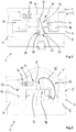
- Fig. 1 shows a steam trap 1 for draining condensate from a steam-carrying system.
- the steam trap 1 has a housing 2 composed of at least two housing parts 4, 4 ', which, which is not shown in more detail, are detachably connected to one another.
- the housing 2 has an inlet 6 for introducing a fluid, in particular condensate and / or steam, into the interior of the housing and an outlet 8 for discharging the fluid, in particular condensate, from the interior of the housing.
- a valve 10 is arranged with two ceramic bodies 12, 12 'arranged so as to be movable relative to one another.
- a first ceramic body 12 is fixedly connected to the housing 2 via a locking ring 14.
- the second ceramic body 12 ' is movably received above the first ceramic body 12.
- the second ceramic body 12 ′ is coupled to a drive device 16, which has a drive means 30.
- the drive device 16 is set up to move the second ceramic body 12 ′ relative to the first ceramic body 12 as a function of physical quantities or measured quantities of the fluid in the interior of the housing 2. Through the adjustment movement of the ceramic body 12 'a passage 18 in the first ceramic body 12 at least partially released. A free flow cross section is formed through the released passage 18, via which the condensate located in the inlet region 20 of the housing flows off in the direction of the outlet region of the housing 2.
- a prestressing device 26 is provided for generating a contact pressure between the contact surfaces 24, 24 'of the first and second ceramic bodies 12, 12' .
- the pretensioning device 26 has a tensioning element 28 designed as a tension spring, which generates a tensile force on the second ceramic body 12 ′ in the direction of the first ceramic body 12.
- the clamping element 28 is connected at one end to the second ceramic body 12 'and at the other end to the housing 2 and causes a restoring force acting on the second ceramic body 12' to open the passage 18.
- FIG. 2 Another embodiment of a steam trap 1 'according to the invention is shown.
- the condensate drain 1 ' comprises a housing 2' with the housing parts 4, 4 ".
- the housing 2 ' has an inlet 6 for introducing the condensate and an outlet 8 for discharging the condensate into or out of the housing 2
- the valve 10 with its ceramic bodies 12, 12 'is almost identical to that in FIG Fig. 1 shown embodiment formed.
- the embodiment of the Fig. 2 has a pretensioning device 26 'with a tensioning element 28', by means of which the contact pressure between the first and second ceramic body is generated.
- the clamping element 28 ' is designed as a clamp, clasp or clip and the second ceramic body 12' is pressed in the direction of the first ceramic body 12 by the bending forces stored in the clamping element, a restoring force also acting to simplify opening of the passage 18.
- the adjustment movement of the second, movable ceramic body 12 'to the passage 18 of the first ceramic body 12 again takes place via the drive device 16 with its drive means 30, which the movement of the second ceramic body 12' depending on a state variable or measurement variable of the in the inlet area 20 of the steam trap 1 ' located fluids regulates.
- the drive device comprises a drive or adjusting means 30 for moving the second Ceramic body 12 '.
- the drive means 30 is designed as an expansion element which has a bellows 32 and a connecting part 34 for coupling the drive means 30 to the housing 2, 2 'and a push rod 36 for connecting the drive means to the second, movable ceramic body 12'.
- the bellows 32 is filled pressure-tight with a fluid filling, in particular a mixture of water and propanol.
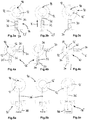
- the movable second ceramic body 12 ' is in a position where the passage 18 in the first ceramic body 12 is partially open. In this position, condensate can thus flow from the inlet area 20 into the outlet area 22 ( 1, 2 ) flow away.
- Fig. 3c the operating state of the steam trap is shown in which the valve 10 is completely closed.
- the passage 18 in the first ceramic body 12 is completely covered by the second ceramic body 12 '.
- the ceramic bodies 12, 12 ' are each designed as cylindrical disk bodies.
- the push rod 36 is connected in the present case to a cylindrical wall section of the second ceramic body 12 ′.
- the drive means 30 is in Fig. 3c , almost completely extended due to the high temperatures in the steam trap. With such an expansion element, stroke distances of approximately 5 to 7 mm can be generated.
- the second ceramic body 12 ' is guided relative to the first ceramic body 12, which can be carried out by means of the drive device 16 alone or alternatively via guide parts arranged on both sides of the adjustment path and the adjustment movement transverse to the longitudinal direction X and thus laterally delimiting.
- FIG. 4a to 4c Another exemplary embodiment of a drive device 16 'according to the invention is shown, which comprises two drive means 30, 30' which move the second, movable ceramic body 12 '.
- the drive means 30, 30 ' which in the embodiment shown are designed as expansion elements, each have a bellows 32, a connecting part 34 and a push rod 36 for coupling to the second ceramic body 12 '.
- the difference between the two drive means 30, 30 'in the exemplary embodiment is the different fluid filling; however, these can also be of identical design.
- the fluid fillings preferably have different compositions of water and propanol. This results in an adjustment movement of the drive means at different temperatures, as explained below.
- Fig. 4a shows the valve 10 in the partially open state, with both drive means 30, 30 'being retracted.
- Fig. 4b shows the operating state with increased temperature inside the condensate drain, the figure making clear that the bellows 32 of the drive means 30 'has already expanded, whereas the bellows 32 of the drive means 30 has retained its original expansion.
- Fig. 4c shows the valve 10 in the closed position, both drive means 30, 30 'now being almost completely extended.
- the guidance of the movable ceramic body 12 ' is ensured in the embodiment shown exclusively via the two drive means 30, 30' of the drive device 16 '.
- the drive means 30, 30 ' are arranged with their connecting parts 34 pivotably on the housing 2' and with their push rods 36 movably on the second ceramic body 12 '.
- the Figures 5a to 5c show the use of a drive device 16 "with an electromechanical drive 38, such as a piezo motor.
- the electromechanical drive 38 is connected via a push rod 36 'to the second ceramic body 12' for an adjustment movement thereof relative to the first ceramic body 12.
- the push rod 36 ' is guided in a sealing manner in order to reliably shield the electromechanical drive 38 against the condensate located inside the condensate drain.
- the movement of the second ceramic body 12 takes place on the basis of the physical state variables and measured variables, such as temperature and level, of the condensate within the condensate, which are not shown in greater detail of the housing of the condensate drain or adjacent to it.
- the measuring device has measuring sensors which record the measured values of the fluid.
- the measuring device transmits the measured values in the form of signals directly or via a control device to the electromechanical drive.
- Fig. 5a shows the partially open
- Fig. 5b shows the closed
- Fig. 5c shows the completely closed state
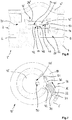
- FIG. 6 A further exemplary embodiment of a steam trap 1 "according to the invention is shown.
- the steam trap 1" has a housing 2 'with housing parts 4, 4 "which are pressure-tightly connected to one another.
- the housing has an inlet 6, an outlet 8 and inside the housing Valve 10 'on Valve 10 'comprises a first ceramic body 42 and a second, movably received ceramic body 42'.
- the ceramic bodies 42, 42 ' are designed as cylindrical disk bodies.
- the first ceramic body 42 is fixed in the interior of the housing via a clamping or locking ring 14.
- the second ceramic body 42 ′ is received on the first ceramic body 42 via a rotary guide 44.
- the rotary guide 44 is formed by means of a circular recess 46 formed on the contact surface 24 of the ceramic body 42 and a pivot 48 corresponding to the recess 46.
- the pivot pin 48 is a material projection projecting on the contact surface 24 'of the second ceramic body 42' in the central region of the second ceramic body 42 '.
- the depression and the pivot pin are each arranged centrally to the central regions of the disk-shaped ceramic bodies 42, 42 '.
- a pretensioning device 26 is provided with a tensioning element designed as a clamp or spiral spring.
- a drive device 16 with only one drive means 30 is used, such as Fig. 7 clarified.
- the drive means 30 is an expansion element with a bellows 32, a connecting part 34 for a connection to the housing 2 'and with a push rod 36 for coupling the drive means 30 to the second ceramic body 42'.
- the drive means 30 expands in its longitudinal direction (arrow X) in accordance with the temperature prevailing inside the condensate drain 1 ", as a result of which the passages 50, 50 'of the first and second ceramic bodies 42, 42' relative
- the push rod 36 of the drive means 30 engages a nose-like projection 51 of the second ceramic body 42 'protruding in the radial direction.
- the connecting part 34 of the drive means 30 is pivotable to the housing 2' and the push rod 36 is movable on the projection 51 added.
- FIG. 8 A further exemplary embodiment of a steam trap 1 '"according to the invention is shown.
- the steam trap 1'" has a housing 2 ".
- the housing 2" comprises an inlet 6, an outlet 8 and a valve 10 "in the interior of the housing 2".
- the valve 10 ′′ has two ceramic bodies 52, 52 ′ as the valve body.
- the ceramic body 52 is in the form of a cylindrical sleeve part with a radial direction through passage 54 extending passage.
- the ceramic body 52 is fixed and fluid-tight on the housing 2 ".
- the ceramic body 52 ' has the shape of a cylindrical bearing part which is rotatably received in the free cross section of the ceramic body 52 designed as a sleeve part.
- the ceramic body 52' has a lengthwise extension Nut 56 on how Fig. 9 shows that extends over a section starting from one end 58 of the ceramic body 52 'for about two thirds of the length of the ceramic body 52'.
- the groove 56 in the second ceramic body 52 ′ corresponds to the passage 54 in the first ceramic body 52 in such a way that with an overlapping alignment, such as Fig. 10 clarifies, a drainage of the condensate is guaranteed from the inlet region 20 in the direction of the outlet region 22.
- a drive device 16 with a drive means 30 designed as an expansion element acts on the second ceramic body 52'.
- the drive means 30 is connected via a lever arm 60 with a Fig. 9 Approach 62 shown coupled to the second ceramic body 52 '.
- the second ceramic body 52 ' which is rotatably slidably received in the first ceramic body 52', is held to the first ceramic body 52 by means of a pretensioning device 26 '.
- the second ceramic body 52 ' rests with a circumferential collar 64 on the end face 66 of the first ceramic body.
- the clamping element 28 '' used to form the pretensioning device 26 ' is a clip, clasp or spiral spring.
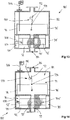
- FIG. 11 and 12 show a further embodiment of a steam trap 80 according to the invention with a housing 82 and a receiving space 84 for condensate formed in a system.
- the housing has an inlet 86 and an outlet 88.
- a valve 90 is arranged between the receiving space 84 and the outlet 88 and has two ceramic bodies 92, 92 ′ which are movable relative to one another.
- the first ceramic body 92 is fixedly connected to the housing 82 and, in the embodiment shown, is designed as a receptacle or sleeve part with a receptacle for the second ceramic body 92 ′, which is movable relative to the first ceramic body.
- the second ceramic body 92 ' is designed as a pin part or piston and, in the embodiment shown, is arranged such that it can be pushed in particular in the direction of the longitudinal axis of the ceramic bodies 92, 92.
- the valve 90 with its two ceramic bodies 92, 92 'is coupled to a drive device 94.
- the valve is moved from a closed position ( Fig. 11 ) in an open position ( Fig. 12 ) or from the open position to the closed position so that passages 99, 99 'in the ceramic body 92, 92' then aligned or shifted to each other.
- the drive device 94 has two fluid lines 96, 96 ′, a first end of each of the two fluid lines being connected to the receiving space 84 for the fluid.
- the opposite end of the fluid line 96 is fluidly connected to a pressure chamber 98 on one side of the valve 90, and the opposite end of the fluid line 96 'is fluidly connected to a pressure chamber 98' on the opposite side of the valve 90.
- a control valve 100, 100 ' is arranged inside each of the fluid lines 96, 96' and is designed to release or shut off the fluid lines.
- the drive device of the steam trap according to the invention is set up to actuate the valve 90 of the steam trap 80 depending on at least one physical variable changing within the housing or in a space connected to the steam trap. If the pressure or the temperature within the receiving space 84 for the condensate drops below a predetermined pressure or below a predetermined temperature, the fluid or pressure-conducting connection between the receiving space 84 is established via the fluid line 96 ′ in the pressure space 98 ′. As a result, the pressure prevailing in the receiving space 84 continues into the pressure space 98 'and acts there on a pressure surface 104' of the ceramic body 92 '. Thus, the valve 90 is in total in its Fig. 12 shown open position moves.
- the temperature and the pressure inside the receiving space 84 usually rise again.
- the temperature and the pressure are recorded in particular by means of a measurement sensor system 106 arranged on the housing and projecting into the receiving space.
- the actuators 102, 102 ' are controlled by the measuring sensor 106 via electrical connecting lines, not shown. If the measured values rise above a presettable limit value, the control valve 100 'closes and the control valve 100 is opened, so that the pressure in the receiving space 84 now acts on the pressure surface 104 of the second ceramic body 92' via the opened fluid line 96 and into the in Fig. 11 shown closed position transferred. The control valve 100 is then closed again.
- the ceramic body 92 'of the valve 90 is positioned in the pressure chamber 98 in the form of a spring element in the pressure chamber 98 when the system is at a standstill or while the system is starting up, if there is only a low system pressure with which the valve 90 cannot be controlled, in which in Fig. 12 held open position shown.
- the 13 and 14 show a further embodiment of a steam trap 80 ', which has a housing 82 and a receiving space 84.
- an inlet 86 and an outlet 88 are provided, a valve 90 being arranged between the receiving space 84 and the outlet 88, with which a specific outlet of the condensate collecting in the receiving space 84 is possible.
- the valve 90 comprises two ceramic bodies 92, 92 ′, the second ceramic body 92 ′ being accommodated within the first ceramic body 92 such that it can be moved.
- Pressure spaces 98, 98 ' are provided on both sides of the valve 90 and are fluidly coupled to the receiving space 84 via fluid lines 96, 96'.
- an actuator 110 Arranged within the receiving space is an actuator 110 which is set up to selectively allow the pressure-conducting connection from the receiving space 84 via one of the fluid lines to the connected pressure space and to allow and / or prevent the other of the fluid lines into the connected pressure space.
- the actuator 110 has in particular an adjusting lever 112 with a valve body 114 arranged on the adjusting lever.
- the adjusting lever 112 which is supported on one side at one end, is in particular pivotally received and is actuated by an actuator 116 designed as an eccentric disk.
- the actuation of the actuator takes place in a manner similar to that in the previous embodiment via the measurement sensor system 106, with which the pressure and temperature conditions and the fill level within the receiving space 84 are monitored.
- Fig. 13 shows the closed position of the valve 90, the one end projecting into the receiving space not being closed by the valve body 114 of the actuator 110, so that the pressure can propagate from the receiving space into the pressure space at the valve 90.
- the pressure then acts on the pressure surface 104, so that the valve is in its closed position and the passages 99, 99 'in the first and second ceramic bodies 92, 92' are not aligned.
- the escape of condensate from the receiving space 84 is hindered.
- the actuator 116 is actuated, as a result of which the actuating lever 112 coupled to the actuator 116 moves into the other one Fig. 14 shown position is pivoted.
- the valve body 114 is moved from the end of the fluid line 96 ′ to the end of the fluid line 96 and now seals the end of the fluid line 96 by means of the valve body 114 arranged on the adjusting lever 112. This increases the pressure in the pressure chamber 98 'and thus on the pressure surface 104' of the second ceramic body 92 ', so that the latter in the in Fig. 14 shown open position passes.
- the passages 99, 99 'of the first and second ceramic bodies 92, 92' are partially or completely aligned, and the condensate can flow out of the receiving space 84 of the condensate drain 80 '.
- the pressure surface 104 is in turn assigned a reset device 108, which moves the valve 90 back into its open position ( Fig. 14 ) supports.
- the illustrated embodiment of a steam trap 80 “basically corresponds to that in FIGS 13 and 14 shown embodiment.
- the condensate drain 80 “comprises an actuator 110 'arranged within the receiving space for regulating the pressure supply via the fluid lines 96, 96' to the respective connected pressure chambers 98, 98 'on both sides of the valve 90.
- the actuator 110 has an adjusting lever 112 with one on it arranged valve body 114, which either seals the end of one fluid line 96 protruding into the receiving space or the end of the other fluid line 96 'protruding into the receiving space depending on its position in the receiving space 84.
- the second becomes Valve body 92 'in the Fig. 15 Shown closed position of the valve 90 or in the in Fig. 16 shown open position moves. In the closed position, the passages 99, 99 'of the ceramic body are offset from one another. In the open position, these are partially or completely aligned with one another.
- the actuator 110 has an actuator 116 ′ which is coupled to the free end of the actuating lever 112 and is designed as an expansion element.
- the actuator 116 which is designed as an expansion element, is set up to automatically change its extent or volume depending on the temperature and / or pressure prevailing in the receiving space 84. As a result, depending on the temperature and / or pressure in the receiving space, the actuating lever is moved either in the direction of the end of the fluid line 96 'or in the direction of the end of the fluid line 96'.
- the mode of operation otherwise corresponds to that in the 13 and 14 shown steam trap 80 '.
- the steam trap 80 "does not require any measuring sensors projecting into the receiving space 84 to regulate the condensate drainage.
- a second actuator 108 is assigned to the second valve body 92 ', which holds the valve 90 in the open position at low system pressures, in particular when the system is at a standstill or while the system is starting up.
- valve body 92 instead of the 11 to 16 mentioned ceramic body 92, 92 'valve body made of a metal or a material with similar solid properties used to form the valve 90.
Landscapes
- Engineering & Computer Science (AREA)
- General Engineering & Computer Science (AREA)
- Mechanical Engineering (AREA)
- Sliding Valves (AREA)
- Lift Valve (AREA)
- Float Valves (AREA)
- Vaporization, Distillation, Condensation, Sublimation, And Cold Traps (AREA)
Claims (16)
- Séparateur de condensat pour l'évacuation de condensat, avec
un boîtier (2, 2', 2", 82),
une entrée (6, 86) réalisée dans le boîtier pour l'introduction de fluide à l'intérieur du boîtier (2, 2', 2", 82),
une sortie (8, 88) réalisée dans le boîtier pour l'évacuation de fluide de l'intérieur du boîtier (2, 2', 2", 82),
une soupape (10, 10', 10", 90) disposée dans le boîtier pour libérer ou fermer une section d'écoulement dans le séparateur de condensat (1, 1', 1", 1'", 80, 80', 80"),
dans lequel la soupape (10, 10', 10", 90) présente un premier corps céramique (12, 42, 52, 92) et un deuxième corps céramique (12', 42', 52', 92') en contact avec le premier corps céramique, dans lequel le premier et le deuxième corps céramique (12, 12', 42, 42', 52, 52', 92, 92') sont conçus et peuvent être déplacés l'un par rapport à l'autre au moyen d'au moins un dispositif d'entraînement (16, 16', 16", 94), de sorte que la section d'écoulement puisse être modifiée,
caractérisé en ce que le dispositif d'entraînement (94) est conçu pour déplacer le deuxième corps céramique (92') par rapport au premier corps céramique (92) au moyen de la pression du fluide dans le séparateur de condensat (80, 80', 80") ou dans un espace relié au séparateur de condensat,
dans lequel au moins une conduite de fluide (96, 96') est prévue, par l'intermédiaire de laquelle la pression de fluide est guidée dans le séparateur de condensat (80, 80', 80") ou l'espace sur une surface de pression (104, 104') sur le deuxième corps céramique (92') pour déplacer le deuxième corps céramique (92') par rapport au premier corps céramique (92). - Séparateur de condensat selon la revendication 1,
caractérisé en ce que le deuxième corps céramique (12', 42', 52', 92') peut être déplacé en glissant par rapport au premier corps céramique (12, 42, 52, 92) au moyen au moins du dispositif d'entraînement (16, 16', 16", 94) et le premier corps céramique (12, 42, 52, 92) est de préférence fixé de manière détachable dans le boîtier. - Séparateur de condensat selon la revendication 1 et/ou 2,
caractérisé en ce que le premier et le deuxième corps céramique (12, 12', 42, 42', 52, 52', 92, 92') sont en appui l'un avec l'autre par l'intermédiaire d'une zone de contact, dans lequel de préférence le premier et le deuxième corps céramique (12, 12', 42, 42') présentent respectivement une surface de contact (24, 24') sensiblement plane. - Séparateur de condensat selon au moins l'une quelconque des revendications précédentes,
caractérisé en ce que les surfaces de contact (24, 24') du premier et du deuxième corps céramique (12, 12', 42, 42', 52, 52', 92, 92') présentent des rugosités différentes ;
et/ou une fraction portante de la surface, qui est réglée sur au moins 75 % ou plus, de préférence d'environ 75 à 90 %, est prévue entre les surfaces de contact (24, 24') ;
et/ou les corps céramiques (12, 12', 42, 42', 52, 52', 92, 92') présentent différentes duretés, dans lequel le premier et/ou le deuxième corps céramique (12, 12', 42, 42', 52, 52', 92, 92') est de préférence formé d'un matériau ou contient un matériau qui est choisi dans le groupe constitué de carbure de silicium, d'oxyde d'aluminium et d'oxyde de zirconium ;
et/ou les surfaces de contact (24, 24') du premier et/ou du deuxième corps céramique (12, 12', 42, 42', 52, 52', 92, 92') présentent un revêtement, de préférence un revêtement en diamant. - Séparateur de condensat selon au moins l'une quelconque des revendications précédentes,
caractérisé par un dispositif de précontrainte (26, 26', 26") destiné à appliquer une force de pression entre le premier et le deuxième corps céramique (12, 12', 42, 42', 52, 52'), dans lequel de préférence le dispositif de précontrainte (26, 26', 26") présente un élément de serrage (28, 28', 28", 28"') déformable élastiquement, dans lequel une partie de l'élément de serrage (28, 28', 28", 28"') est reliée au deuxième corps céramique (12', 42', 52') et au moins une partie au boîtier (2, 2', 2'') ou au premier corps céramique (12, 42, 52), et
dans lequel l'élément de serrage (28, 28', 28", 28"') est réalisé de préférence en tant que ressort de traction, ressort spiral, clip ou agrafe. - Séparateur de condensat selon au moins l'une quelconque des revendications précédentes,
caractérisé en ce qu'au moins un des corps céramiques (12, 12', 42, 42'), de préférence les deux corps céramiques, sont réalisés sensiblement en forme de plaquette et peuvent coulisser l'un par rapport à l'autre, de préférence l'un vers l'autre ;
et/ou le premier corps céramique (52, 92) est réalisé en tant que pièce de logement ou de manchon et le deuxième corps céramique (52', 92') en tant que pièce de tenon mobile en translation ou logée mobile en rotation dans la pièce de logement ou de manchon ;
et/ou au moins un des corps céramiques (12, 42, 42', 52), de préférence le premier corps céramique (12, 42, 52), présente un passage (18, 50, 50', 54) pour le fluide, dans lequel l'autre, de préférence le deuxième corps céramique (12', 42', 52') mobile, peut coulisser par rapport au passage (18, 50, 54) au moyen du dispositif d'entraînement, de sorte que la section d'écoulement pour le fluide puisse être modifiée de préférence en continu entre une position fermée et une position ouverte. - Séparateur de condensat selon au moins l'une quelconque des revendications précédentes,
dans lequel le premier et le deuxième corps céramique (92, 92') présentent un passage (99, 99') pour le fluide à évacuer, dans lequel le deuxième corps céramique (92') mobile avec son passage (99') peut coulisser au moyen du dispositif d'entraînement (94) vers le passage (99) dans le premier corps céramique (92), de sorte que la section d'écoulement pour le fluide puisse être réglée de préférence en continu entre la position fermée et la position ouverte ; et/ou au moins un des corps céramiques (12, 12', 42, 42', 52, 52', 92, 92') peut être guidé par rapport au premier corps céramique (12, 42, 52) au moyen d'un guidage,
dans lequel de préférence le guidage présente des éléments de guidage en prise les uns avec les autres, lesquels sont réalisés en tant qu'évidement (46) ou rainure dans un corps céramique (12, 42, 52) et en tant que partie saillante de matériau (48) correspondante sur l'autre corps céramique (12', 42', 52'). - Séparateur de condensat selon au moins l'une quelconque des revendications précédentes,
caractérisé en ce qu'une première conduite de fluide (96) peut être en liaison fluidique avec le séparateur de condensat (80, 80', 80") ou l'espace et avec une chambre de pression (98) disposée sur un côté du deuxième corps céramique (92') mobile, et une deuxième conduite de fluide (96') peut être en liaison fluidique avec le séparateur de condensat (80, 80', 80") ou l'espace et avec une chambre de pression (98') disposée sur les autres côtés opposés du deuxième corps céramique (92') mobile, dans lequel les taux de compression dans les chambres de pression (98, 98') des deux côtés du corps céramique (92') mobile sont réglables par l'intermédiaire des conduites de fluide (96, 96'), de sorte que le deuxième corps céramique (92') puisse être déplacé de préférence dans des directions opposées. - Séparateur de condensat selon la revendication 8,
caractérisé en ce que respectivement une soupape de commande (100, 100') pouvant être actionnée au moyen d'un mécanisme d'actionnement (102, 102') pour libérer ou fermer les conduites de fluide (96, 96') est disposée dans la première et/ou la deuxième conduite de fluide (96, 96'),
ou qu'un entraînement d'actionnement (110, 110'), en particulier un levier d'actionnement (112) mobile, de préférence pivotant, avec un corps de soupape (114) disposé sur celui-ci, lequel est conçu pour sélectivement autoriser l'amenée de pression dans l'une des conduites de fluide (96, 96') et l'empêcher dans l'autre des conduites de fluide (96, 96'), est associé à la première et à la deuxième conduite de fluide (96, 96') dans le séparateur de condensat (80, 80', 80") ou dans l'espace relié au séparateur de condensat. - Séparateur de condensat selon la revendication 9,
caractérisé en ce que l'entraînement d'actionnement (110, 110') peut être déplacé entre ses positions de travail libérant soit la première soit la deuxième des conduites de fluide (96, 96') au moyen d'un élément d'actionnement (116, 116') pouvant être commandé en fonction d'au moins une grandeur physique variant à l'intérieur du boîtier de séparateur de condensat (2, 2', 2") ou l'espace,
dans lequel l'élément d'actionnement (116, 116') présente de préférence un élément extensible, élément de soufflet, entraînement électrique, entraînement électromécanique, entraînement pneumatique et/ou entraînement bimétallique commandé par température et/ou pression du fluide s'accumulant dans le séparateur de condensat. - Séparateur de condensat selon l'une quelconque des revendications 6 à 10,
caractérisé en ce que le premier corps céramique (52, 92) est réalisé sensiblement en tant que tube cylindrique et le deuxième corps céramique en tant que piston cylindrique (52', 92'), et les passages (50, 99, 99') pour le fluide à évacuer s'étendent de manière disposée sensiblement perpendiculairement à l'axe longitudinal du premier et du deuxième corps céramique (52, 52', 92, 92'). - Séparateur de condensat selon au moins l'une quelconque des revendications précédentes,
caractérisé en ce que le dispositif d'entraînement (16, 16', 16", 94) présente au moins un, de préférence deux, moyens d'entraînement (30, 30') destinés à déplacer un des corps céramiques (12, 12', 42, 42', 52, 52', 92, 92'), dans lequel un moyen d'entraînement ou les deux moyens d'entraînement (30, 30') est/sont conçu(s) pour déplacer de préférence le deuxième corps céramique (12', 42', 52') en fonction d'une grandeur physique variant à l'intérieur du boîtier de séparateur de condensat (2, 2', 2'') ou grandeur de mesure détectée. - Séparateur de condensat selon au moins l'une quelconque des revendications précédentes,
caractérisé en ce qu'au moins deux moyens d'entraînement (30, 30') destinés à déplacer de préférence le deuxième corps céramique (12', 42', 52') sont prévus, dans lequel les moyens d'entraînement (30, 30') agissent sur le corps céramique (12', 42', 52') de préférence dans des directions d'action différentes, de préférence dans des directions d'action s'étendant de manière angulaire les unes par rapport aux autres, de préférence selon un angle dans la plage d'environ 70° à environ 110°, et/ou dans lequel de préférence le premier moyen d'entraînement (30) déplace le corps céramique dans une première plage de températures ΔT et le deuxième moyen d'entraînement (30') déplace le corps céramique dans une deuxième plage de températures ΔT, dans lequel la première et la deuxième plage de températures présentent des écarts différents par rapport à la courbe d'ébullition. - Séparateur de condensat selon au moins l'une quelconque des revendications précédentes,
caractérisé par au moins un dispositif de mesure de température destiné à relever la température de fluide à l'intérieur du boîtier (2, 2', 2'') ou au voisinage du boîtier (2, 2', 2"), dans lequel le dispositif de mesure de température est couplé au dispositif d'entraînement (16, 16', 16", 94) avec transmission de signaux de façon directe ou par l'intermédiaire d'un dispositif de commande,
dans lequel le dispositif de mesure de température est réalisé de préférence en tant que thermomètre à résistance ou thermoélément. - Séparateur de condensat selon au moins l'une quelconque des revendications précédentes,
caractérisé par un dispositif de production d'énergie électrique destiné à produire de l'énergie électrique à partir d'énergie thermique contenue dans le fluide, qui est réalisé de préférence en tant qu'élément Peltier et conçu pour alimenter en énergie au moins le ou les moyens d'entraînement (30, 30') et/ou un dispositif de commande. - Procédé pour évacuer un condensat dans un séparateur de condensat, comprenant les étapes suivantes :d'introduction d'un fluide dans un séparateur de condensat (1, 1', 1", 1''', 80, 80', 80"), qui présente un boîtier (2, 2', 2", 82), une entrée (6, 86) et une sortie (8, 88) et une soupape (10, 10', 10", 90),de déplacement d'un corps céramique (12', 42', 52', 92') par rapport à un autre corps céramique (12, 42, 52, 92) en contact avec le corps céramique (12', 42', 52', 92'), de sorte qu'une section d'écoulement pour le fluide soit modifiée,dans le cas de la section d'écoulement libre, d'évacuation du fluide du boîtier (2, 2', 2", 82) par la sortie (8, 88),dans lequel le déplacement d'un des corps céramiques (12', 42', 52', 92') par rapport à l'autre corps céramique (12, 42, 52, 92) est réalisé en fonction de la pression du fluide dans le séparateur de condensat (80, 80', 80") ou dans un espace relié au séparateur de condensat, afin de déplacer le deuxième corps céramique (92') par rapport au premier corps céramique (92),dans lequel la pression de fluide est introduite par l'intermédiaire d'une conduite de fluide dans le séparateur de condensat (80, 80', 80") ou l'espace sur une surface de pression (104, 104') sur le deuxième corps céramique (92') pour déplacer le deuxième corps céramique (92') par rapport au premier corps céramique (92) ;dans lequel le déplacement d'un des corps céramiques (12', 42', 52', 92') par rapport à l'autre corps céramique (12, 42, 52, 92) comprend de préférence en outre l'étape suivante :
de glissement de surfaces de contact (24, 24') planes des corps céramiques (12, 12', 42, 42') l'une sur l'autre ou de surfaces de contact cylindriques des corps céramiques (52, 52', 92, 92') l'une dans l'autre.
Applications Claiming Priority (1)
| Application Number | Priority Date | Filing Date | Title |
|---|---|---|---|
| DE102016200863.3A DE102016200863B4 (de) | 2016-01-21 | 2016-01-21 | Kondensatableiter und Verfahren zum Ableiten von Kondensat |
Publications (3)
| Publication Number | Publication Date |
|---|---|
| EP3205922A2 EP3205922A2 (fr) | 2017-08-16 |
| EP3205922A3 EP3205922A3 (fr) | 2017-11-15 |
| EP3205922B1 true EP3205922B1 (fr) | 2020-01-08 |
Family
ID=57906464
Family Applications (1)
| Application Number | Title | Priority Date | Filing Date |
|---|---|---|---|
| EP17152699.9A Active EP3205922B1 (fr) | 2016-01-21 | 2017-01-23 | Séparateur de condensat et procédé de séparation de condensat |
Country Status (2)
| Country | Link |
|---|---|
| EP (1) | EP3205922B1 (fr) |
| DE (1) | DE102016200863B4 (fr) |
Families Citing this family (2)
| Publication number | Priority date | Publication date | Assignee | Title |
|---|---|---|---|---|
| DE102022114720A1 (de) * | 2022-06-10 | 2023-12-21 | Gestra Ag | Kondensatableiter zum Ableiten von Kondensat |
| CN118843292B (zh) * | 2024-07-21 | 2025-05-09 | 浙江商储数智能源科技有限公司 | 一种安全性高的液冷装置及其冷却方法 |
Family Cites Families (22)
| Publication number | Priority date | Publication date | Assignee | Title |
|---|---|---|---|---|
| GB191306993A (en) * | 1912-03-22 | 1913-10-09 | Paul Charles Ribes | An Improved Steam Trap. |
| US1728677A (en) * | 1924-01-12 | 1929-09-17 | Robert H George | Drain valve |
| US1728678A (en) * | 1924-07-29 | 1929-09-17 | Robert H George | Drain valve |
| DE665150C (de) * | 1936-01-12 | 1938-09-19 | Konrad Petermichl | Ableiter fuer das Niederschlagwasser aus Dampf, Pressluft usw. |
| US2627869A (en) * | 1944-10-18 | 1953-02-10 | Edward J Whalen | Automatic drain valve for air lines |
| US2485232A (en) * | 1947-03-06 | 1949-10-18 | George T Brown | Drainage valve system |
| DE803866C (de) * | 1949-03-22 | 1951-04-12 | Gustav Friedrich Gerdts | Ableitungskoerper fuer Dampfwasserableiter |
| FR1171741A (fr) * | 1957-04-18 | 1959-01-29 | Purgeur automatique | |
| GB2129525B (en) | 1982-10-12 | 1986-02-26 | Loomhurst Ltd | Drain valves |
| DE3447927C2 (de) | 1984-04-03 | 1986-01-23 | Krohne Meßtechnik GmbH & Co KG, 4100 Duisburg | Absperr- und Regelorgan |
| JP2559275B2 (ja) | 1989-02-25 | 1996-12-04 | 株式会社 ユニスン | スチームトラップ及び復水排出装置 |
| DE4212874A1 (de) | 1992-04-17 | 1993-10-21 | Hoechst Ceram Tec Ag | Ventilscheiben aus siliciuminfiltriertem Siliciumcarbid |
| EP0718256B1 (fr) | 1994-12-23 | 1999-06-30 | Maruwa Ceramic Co., Ltd. | Pièce coulissante et procédé pour sa fabrication |
| JP2750828B2 (ja) | 1995-02-28 | 1998-05-13 | 株式会社竹村製作所 | 水抜栓装置 |
| DE29620068U1 (de) * | 1996-11-12 | 1997-03-13 | Wille, Werner, 90592 Schwarzenbruck | Kondensatableiter |
| NL1011177C2 (nl) | 1999-01-29 | 2000-08-01 | Sara Lee De Nv | Keramische klep. |
| US20050016592A1 (en) | 2001-11-13 | 2005-01-27 | Jeromson Peter James | Process control valve |
| US7096880B2 (en) * | 2003-07-09 | 2006-08-29 | Kabushiki Kaisha Motoyamaseisakusho | Float type steam trap |
| DE102007020361A1 (de) | 2007-04-30 | 2008-11-06 | Marco Systemanalyse Und Entwicklung Gmbh | Ventil |
| DE102007035969A1 (de) | 2007-07-30 | 2009-02-05 | Hidde, Axel R., Dr. | Ventilbaukasten mit Keramikventil |
| GB2457924B (en) | 2008-02-28 | 2012-04-25 | Spirax Sarco Ltd | Developments in or relating to steam trap monitoring |
| DE202013103967U1 (de) | 2013-09-03 | 2013-10-23 | Bürkert Werke GmbH | Drehschieberventil |
-
2016
- 2016-01-21 DE DE102016200863.3A patent/DE102016200863B4/de active Active
-
2017
- 2017-01-23 EP EP17152699.9A patent/EP3205922B1/fr active Active
Non-Patent Citations (1)
| Title |
|---|
| None * |
Also Published As
| Publication number | Publication date |
|---|---|
| DE102016200863B4 (de) | 2021-12-16 |
| EP3205922A2 (fr) | 2017-08-16 |
| EP3205922A3 (fr) | 2017-11-15 |
| DE102016200863A1 (de) | 2017-07-27 |
Similar Documents
| Publication | Publication Date | Title |
|---|---|---|
| EP2064608B1 (fr) | Soupape thermostatique pour la régulation d'un flux massique | |
| AT517217B1 (de) | Längenverstellbare pleuelstange | |
| EP2458471B1 (fr) | Dispositif thermostatique pour le réglage d'un flux de matière | |
| WO2016203047A1 (fr) | Bielle réglable en longueur | |
| EP2054691A1 (fr) | Soupape de dérivation pour refroidisseur raccordé en aval d'une machine hydraulique | |
| EP2743552A1 (fr) | Soupape | |
| EP2628985B1 (fr) | Dispositif de protection contre les échaudures | |
| DE102016200863B4 (de) | Kondensatableiter und Verfahren zum Ableiten von Kondensat | |
| DE19963499A1 (de) | Ventilanordnung | |
| DE69300578T2 (de) | Verbesserungen von thermostatischen Kappen und Mischungsventilen mit solchen Kappen. | |
| DE102019103913A1 (de) | Thermostatventil | |
| DE2448383C2 (de) | Temperaturgesteuertes Ventil | |
| DE102005001842B4 (de) | Thermostataufsatz für ein Heizungs- oder Kälteventil | |
| WO2003091816A2 (fr) | Soupape de regulation pour systemes de climatisation | |
| DE2609635B2 (de) | Rückdichtung einer Armatur für heiße Medien | |
| DE102016124675A1 (de) | Thermostatventil für eine Verbrennungskraftmaschine | |
| DE102016216609A1 (de) | Wegaufnehmer | |
| DE2206827A1 (de) | Regelventil mit doppeltem Sitz | |
| DE102013107283B4 (de) | Thermostatisches Sicherheitsventil für gasförmige oder fluide Medien | |
| DE102014224414A1 (de) | Einrichtung zur Integration eines Bypassventils in einen Kühlkreislauf | |
| DE202015100834U1 (de) | Durchflussmengenregler für eine Heizungsanlage | |
| EP3798428B1 (fr) | Soupape de commande et / ou de régulation d'un flux de fluide | |
| DE102005059418A1 (de) | Einrichtung zur Steuerung eines Wärmeflusses | |
| EP4143469B1 (fr) | Dispositif de soupape, en particulier soupape de liquide d'essuie-glace | |
| DE102007031356A1 (de) | Dehnstoffelement |
Legal Events
| Date | Code | Title | Description |
|---|---|---|---|
| PUAI | Public reference made under article 153(3) epc to a published international application that has entered the european phase |
Free format text: ORIGINAL CODE: 0009012 |
|
| STAA | Information on the status of an ep patent application or granted ep patent |
Free format text: STATUS: THE APPLICATION HAS BEEN PUBLISHED |
|
| AK | Designated contracting states |
Kind code of ref document: A2 Designated state(s): AL AT BE BG CH CY CZ DE DK EE ES FI FR GB GR HR HU IE IS IT LI LT LU LV MC MK MT NL NO PL PT RO RS SE SI SK SM TR |
|
| AX | Request for extension of the european patent |
Extension state: BA ME |
|
| PUAL | Search report despatched |
Free format text: ORIGINAL CODE: 0009013 |
|
| AK | Designated contracting states |
Kind code of ref document: A3 Designated state(s): AL AT BE BG CH CY CZ DE DK EE ES FI FR GB GR HR HU IE IS IT LI LT LU LV MC MK MT NL NO PL PT RO RS SE SI SK SM TR |
|
| AX | Request for extension of the european patent |
Extension state: BA ME |
|
| RIC1 | Information provided on ipc code assigned before grant |
Ipc: F16T 1/42 20060101ALI20171012BHEP Ipc: F16T 1/38 20060101ALI20171012BHEP Ipc: F16T 1/12 20060101AFI20171012BHEP |
|
| STAA | Information on the status of an ep patent application or granted ep patent |
Free format text: STATUS: REQUEST FOR EXAMINATION WAS MADE |
|
| 17P | Request for examination filed |
Effective date: 20180515 |
|
| RBV | Designated contracting states (corrected) |
Designated state(s): AL AT BE BG CH CY CZ DE DK EE ES FI FR GB GR HR HU IE IS IT LI LT LU LV MC MK MT NL NO PL PT RO RS SE SI SK SM TR |
|
| GRAP | Despatch of communication of intention to grant a patent |
Free format text: ORIGINAL CODE: EPIDOSNIGR1 |
|
| STAA | Information on the status of an ep patent application or granted ep patent |
Free format text: STATUS: GRANT OF PATENT IS INTENDED |
|
| INTG | Intention to grant announced |
Effective date: 20190724 |
|
| GRAS | Grant fee paid |
Free format text: ORIGINAL CODE: EPIDOSNIGR3 |
|
| GRAA | (expected) grant |
Free format text: ORIGINAL CODE: 0009210 |
|
| STAA | Information on the status of an ep patent application or granted ep patent |
Free format text: STATUS: THE PATENT HAS BEEN GRANTED |
|
| AK | Designated contracting states |
Kind code of ref document: B1 Designated state(s): AL AT BE BG CH CY CZ DE DK EE ES FI FR GB GR HR HU IE IS IT LI LT LU LV MC MK MT NL NO PL PT RO RS SE SI SK SM TR |
|
| REG | Reference to a national code |
Ref country code: GB Ref legal event code: FG4D Free format text: NOT ENGLISH |
|
| REG | Reference to a national code |
Ref country code: CH Ref legal event code: EP |
|
| REG | Reference to a national code |
Ref country code: DE Ref legal event code: R096 Ref document number: 502017003403 Country of ref document: DE |
|
| REG | Reference to a national code |
Ref country code: IE Ref legal event code: FG4D Free format text: LANGUAGE OF EP DOCUMENT: GERMAN |
|
| REG | Reference to a national code |
Ref country code: AT Ref legal event code: REF Ref document number: 1223149 Country of ref document: AT Kind code of ref document: T Effective date: 20200215 |
|
| REG | Reference to a national code |
Ref country code: NL Ref legal event code: MP Effective date: 20200108 |
|
| REG | Reference to a national code |
Ref country code: LT Ref legal event code: MG4D |
|
| PG25 | Lapsed in a contracting state [announced via postgrant information from national office to epo] |
Ref country code: NO Free format text: LAPSE BECAUSE OF FAILURE TO SUBMIT A TRANSLATION OF THE DESCRIPTION OR TO PAY THE FEE WITHIN THE PRESCRIBED TIME-LIMIT Effective date: 20200408 Ref country code: LT Free format text: LAPSE BECAUSE OF FAILURE TO SUBMIT A TRANSLATION OF THE DESCRIPTION OR TO PAY THE FEE WITHIN THE PRESCRIBED TIME-LIMIT Effective date: 20200108 Ref country code: NL Free format text: LAPSE BECAUSE OF FAILURE TO SUBMIT A TRANSLATION OF THE DESCRIPTION OR TO PAY THE FEE WITHIN THE PRESCRIBED TIME-LIMIT Effective date: 20200108 Ref country code: RS Free format text: LAPSE BECAUSE OF FAILURE TO SUBMIT A TRANSLATION OF THE DESCRIPTION OR TO PAY THE FEE WITHIN THE PRESCRIBED TIME-LIMIT Effective date: 20200108 Ref country code: PT Free format text: LAPSE BECAUSE OF FAILURE TO SUBMIT A TRANSLATION OF THE DESCRIPTION OR TO PAY THE FEE WITHIN THE PRESCRIBED TIME-LIMIT Effective date: 20200531 Ref country code: FI Free format text: LAPSE BECAUSE OF FAILURE TO SUBMIT A TRANSLATION OF THE DESCRIPTION OR TO PAY THE FEE WITHIN THE PRESCRIBED TIME-LIMIT Effective date: 20200108 |
|
| PG25 | Lapsed in a contracting state [announced via postgrant information from national office to epo] |
Ref country code: HR Free format text: LAPSE BECAUSE OF FAILURE TO SUBMIT A TRANSLATION OF THE DESCRIPTION OR TO PAY THE FEE WITHIN THE PRESCRIBED TIME-LIMIT Effective date: 20200108 Ref country code: GR Free format text: LAPSE BECAUSE OF FAILURE TO SUBMIT A TRANSLATION OF THE DESCRIPTION OR TO PAY THE FEE WITHIN THE PRESCRIBED TIME-LIMIT Effective date: 20200409 Ref country code: SE Free format text: LAPSE BECAUSE OF FAILURE TO SUBMIT A TRANSLATION OF THE DESCRIPTION OR TO PAY THE FEE WITHIN THE PRESCRIBED TIME-LIMIT Effective date: 20200108 Ref country code: LV Free format text: LAPSE BECAUSE OF FAILURE TO SUBMIT A TRANSLATION OF THE DESCRIPTION OR TO PAY THE FEE WITHIN THE PRESCRIBED TIME-LIMIT Effective date: 20200108 Ref country code: BG Free format text: LAPSE BECAUSE OF FAILURE TO SUBMIT A TRANSLATION OF THE DESCRIPTION OR TO PAY THE FEE WITHIN THE PRESCRIBED TIME-LIMIT Effective date: 20200408 Ref country code: IS Free format text: LAPSE BECAUSE OF FAILURE TO SUBMIT A TRANSLATION OF THE DESCRIPTION OR TO PAY THE FEE WITHIN THE PRESCRIBED TIME-LIMIT Effective date: 20200508 |
|
| REG | Reference to a national code |
Ref country code: CH Ref legal event code: PL |
|
| REG | Reference to a national code |
Ref country code: DE Ref legal event code: R097 Ref document number: 502017003403 Country of ref document: DE |
|
| REG | Reference to a national code |
Ref country code: BE Ref legal event code: MM Effective date: 20200131 |
|
| PG25 | Lapsed in a contracting state [announced via postgrant information from national office to epo] |
Ref country code: CZ Free format text: LAPSE BECAUSE OF FAILURE TO SUBMIT A TRANSLATION OF THE DESCRIPTION OR TO PAY THE FEE WITHIN THE PRESCRIBED TIME-LIMIT Effective date: 20200108 Ref country code: RO Free format text: LAPSE BECAUSE OF FAILURE TO SUBMIT A TRANSLATION OF THE DESCRIPTION OR TO PAY THE FEE WITHIN THE PRESCRIBED TIME-LIMIT Effective date: 20200108 Ref country code: EE Free format text: LAPSE BECAUSE OF FAILURE TO SUBMIT A TRANSLATION OF THE DESCRIPTION OR TO PAY THE FEE WITHIN THE PRESCRIBED TIME-LIMIT Effective date: 20200108 Ref country code: SM Free format text: LAPSE BECAUSE OF FAILURE TO SUBMIT A TRANSLATION OF THE DESCRIPTION OR TO PAY THE FEE WITHIN THE PRESCRIBED TIME-LIMIT Effective date: 20200108 Ref country code: LU Free format text: LAPSE BECAUSE OF NON-PAYMENT OF DUE FEES Effective date: 20200123 Ref country code: SK Free format text: LAPSE BECAUSE OF FAILURE TO SUBMIT A TRANSLATION OF THE DESCRIPTION OR TO PAY THE FEE WITHIN THE PRESCRIBED TIME-LIMIT Effective date: 20200108 Ref country code: DK Free format text: LAPSE BECAUSE OF FAILURE TO SUBMIT A TRANSLATION OF THE DESCRIPTION OR TO PAY THE FEE WITHIN THE PRESCRIBED TIME-LIMIT Effective date: 20200108 Ref country code: MC Free format text: LAPSE BECAUSE OF FAILURE TO SUBMIT A TRANSLATION OF THE DESCRIPTION OR TO PAY THE FEE WITHIN THE PRESCRIBED TIME-LIMIT Effective date: 20200108 Ref country code: ES Free format text: LAPSE BECAUSE OF FAILURE TO SUBMIT A TRANSLATION OF THE DESCRIPTION OR TO PAY THE FEE WITHIN THE PRESCRIBED TIME-LIMIT Effective date: 20200108 |
|
| PLBE | No opposition filed within time limit |
Free format text: ORIGINAL CODE: 0009261 |
|
| STAA | Information on the status of an ep patent application or granted ep patent |
Free format text: STATUS: NO OPPOSITION FILED WITHIN TIME LIMIT |
|
| PG25 | Lapsed in a contracting state [announced via postgrant information from national office to epo] |
Ref country code: BE Free format text: LAPSE BECAUSE OF NON-PAYMENT OF DUE FEES Effective date: 20200131 Ref country code: LI Free format text: LAPSE BECAUSE OF NON-PAYMENT OF DUE FEES Effective date: 20200131 Ref country code: CH Free format text: LAPSE BECAUSE OF NON-PAYMENT OF DUE FEES Effective date: 20200131 |
|
| 26N | No opposition filed |
Effective date: 20201009 |
|
| PG25 | Lapsed in a contracting state [announced via postgrant information from national office to epo] |
Ref country code: FR Free format text: LAPSE BECAUSE OF NON-PAYMENT OF DUE FEES Effective date: 20200308 Ref country code: IE Free format text: LAPSE BECAUSE OF NON-PAYMENT OF DUE FEES Effective date: 20200123 Ref country code: IT Free format text: LAPSE BECAUSE OF FAILURE TO SUBMIT A TRANSLATION OF THE DESCRIPTION OR TO PAY THE FEE WITHIN THE PRESCRIBED TIME-LIMIT Effective date: 20200108 |
|
| PG25 | Lapsed in a contracting state [announced via postgrant information from national office to epo] |
Ref country code: PL Free format text: LAPSE BECAUSE OF FAILURE TO SUBMIT A TRANSLATION OF THE DESCRIPTION OR TO PAY THE FEE WITHIN THE PRESCRIBED TIME-LIMIT Effective date: 20200108 Ref country code: SI Free format text: LAPSE BECAUSE OF FAILURE TO SUBMIT A TRANSLATION OF THE DESCRIPTION OR TO PAY THE FEE WITHIN THE PRESCRIBED TIME-LIMIT Effective date: 20200108 |
|
| GBPC | Gb: european patent ceased through non-payment of renewal fee |
Effective date: 20210123 |
|
| PG25 | Lapsed in a contracting state [announced via postgrant information from national office to epo] |
Ref country code: GB Free format text: LAPSE BECAUSE OF NON-PAYMENT OF DUE FEES Effective date: 20210123 |
|
| PGFP | Annual fee paid to national office [announced via postgrant information from national office to epo] |
Ref country code: DE Payment date: 20220207 Year of fee payment: 6 |
|
| PG25 | Lapsed in a contracting state [announced via postgrant information from national office to epo] |
Ref country code: TR Free format text: LAPSE BECAUSE OF FAILURE TO SUBMIT A TRANSLATION OF THE DESCRIPTION OR TO PAY THE FEE WITHIN THE PRESCRIBED TIME-LIMIT Effective date: 20200108 Ref country code: MT Free format text: LAPSE BECAUSE OF FAILURE TO SUBMIT A TRANSLATION OF THE DESCRIPTION OR TO PAY THE FEE WITHIN THE PRESCRIBED TIME-LIMIT Effective date: 20200108 Ref country code: CY Free format text: LAPSE BECAUSE OF FAILURE TO SUBMIT A TRANSLATION OF THE DESCRIPTION OR TO PAY THE FEE WITHIN THE PRESCRIBED TIME-LIMIT Effective date: 20200108 |
|
| PG25 | Lapsed in a contracting state [announced via postgrant information from national office to epo] |
Ref country code: MK Free format text: LAPSE BECAUSE OF FAILURE TO SUBMIT A TRANSLATION OF THE DESCRIPTION OR TO PAY THE FEE WITHIN THE PRESCRIBED TIME-LIMIT Effective date: 20200108 Ref country code: AL Free format text: LAPSE BECAUSE OF FAILURE TO SUBMIT A TRANSLATION OF THE DESCRIPTION OR TO PAY THE FEE WITHIN THE PRESCRIBED TIME-LIMIT Effective date: 20200108 |
|
| REG | Reference to a national code |
Ref country code: AT Ref legal event code: MM01 Ref document number: 1223149 Country of ref document: AT Kind code of ref document: T Effective date: 20220123 |
|
| PG25 | Lapsed in a contracting state [announced via postgrant information from national office to epo] |
Ref country code: AT Free format text: LAPSE BECAUSE OF NON-PAYMENT OF DUE FEES Effective date: 20220123 |
|
| REG | Reference to a national code |
Ref country code: DE Ref legal event code: R119 Ref document number: 502017003403 Country of ref document: DE |
|
| REG | Reference to a national code |
Ref country code: DE Ref legal event code: R082 Ref document number: 502017003403 Country of ref document: DE Representative=s name: HL KEMPNER PATENTANWALT, RECHTSANWALT, SOLICIT, DE |
|
| PG25 | Lapsed in a contracting state [announced via postgrant information from national office to epo] |
Ref country code: DE Free format text: LAPSE BECAUSE OF NON-PAYMENT OF DUE FEES Effective date: 20230801 |