EP3205962A1 - Traitement de flux de gaz naturel riche en azote - Google Patents
Traitement de flux de gaz naturel riche en azote Download PDFInfo
- Publication number
- EP3205962A1 EP3205962A1 EP17155467.8A EP17155467A EP3205962A1 EP 3205962 A1 EP3205962 A1 EP 3205962A1 EP 17155467 A EP17155467 A EP 17155467A EP 3205962 A1 EP3205962 A1 EP 3205962A1
- Authority
- EP
- European Patent Office
- Prior art keywords
- helium
- nitrogen
- natural gas
- methane
- enriched
- Prior art date
- Legal status (The legal status is an assumption and is not a legal conclusion. Google has not performed a legal analysis and makes no representation as to the accuracy of the status listed.)
- Withdrawn
Links
- VNWKTOKETHGBQD-UHFFFAOYSA-N methane Chemical compound C VNWKTOKETHGBQD-UHFFFAOYSA-N 0.000 title claims abstract description 512
- IJGRMHOSHXDMSA-UHFFFAOYSA-N Atomic nitrogen Chemical compound N#N IJGRMHOSHXDMSA-UHFFFAOYSA-N 0.000 title claims abstract description 454
- 229910052757 nitrogen Inorganic materials 0.000 title claims abstract description 214
- 239000003345 natural gas Substances 0.000 title claims abstract description 145
- 239000007788 liquid Substances 0.000 claims abstract description 219
- 239000001307 helium Substances 0.000 claims abstract description 208
- 229910052734 helium Inorganic materials 0.000 claims abstract description 208
- SWQJXJOGLNCZEY-UHFFFAOYSA-N helium atom Chemical compound [He] SWQJXJOGLNCZEY-UHFFFAOYSA-N 0.000 claims abstract description 208
- 238000011084 recovery Methods 0.000 claims abstract description 123
- 238000004821 distillation Methods 0.000 claims abstract description 27
- 238000002203 pretreatment Methods 0.000 claims abstract description 16
- 239000012535 impurity Substances 0.000 claims abstract description 10
- 238000000034 method Methods 0.000 claims description 123
- 229930195733 hydrocarbon Natural products 0.000 claims description 64
- 150000002430 hydrocarbons Chemical class 0.000 claims description 64
- 239000004215 Carbon black (E152) Substances 0.000 claims description 40
- 238000001816 cooling Methods 0.000 claims description 17
- 230000018044 dehydration Effects 0.000 claims description 4
- 238000006297 dehydration reaction Methods 0.000 claims description 4
- 239000003507 refrigerant Substances 0.000 claims description 3
- 239000007789 gas Substances 0.000 abstract description 69
- 239000000047 product Substances 0.000 description 38
- 238000000746 purification Methods 0.000 description 34
- 229910001873 dinitrogen Inorganic materials 0.000 description 26
- 238000005057 refrigeration Methods 0.000 description 24
- 238000004519 manufacturing process Methods 0.000 description 23
- 239000012071 phase Substances 0.000 description 22
- CURLTUGMZLYLDI-UHFFFAOYSA-N Carbon dioxide Chemical compound O=C=O CURLTUGMZLYLDI-UHFFFAOYSA-N 0.000 description 20
- ATUOYWHBWRKTHZ-UHFFFAOYSA-N Propane Chemical class CCC ATUOYWHBWRKTHZ-UHFFFAOYSA-N 0.000 description 17
- 238000010992 reflux Methods 0.000 description 17
- 229910002092 carbon dioxide Inorganic materials 0.000 description 14
- 230000008016 vaporization Effects 0.000 description 14
- 239000012530 fluid Substances 0.000 description 13
- 241000196324 Embryophyta Species 0.000 description 11
- XLYOFNOQVPJJNP-UHFFFAOYSA-N water Substances O XLYOFNOQVPJJNP-UHFFFAOYSA-N 0.000 description 11
- 229910001868 water Inorganic materials 0.000 description 11
- RWSOTUBLDIXVET-UHFFFAOYSA-N Dihydrogen sulfide Chemical compound S RWSOTUBLDIXVET-UHFFFAOYSA-N 0.000 description 10
- OTMSDBZUPAUEDD-UHFFFAOYSA-N Ethane Chemical compound CC OTMSDBZUPAUEDD-UHFFFAOYSA-N 0.000 description 10
- 241000183024 Populus tremula Species 0.000 description 10
- 229910000037 hydrogen sulfide Inorganic materials 0.000 description 10
- 238000005094 computer simulation Methods 0.000 description 9
- 235000013849 propane Nutrition 0.000 description 9
- 239000001294 propane Substances 0.000 description 8
- 230000000052 comparative effect Effects 0.000 description 7
- 239000002737 fuel gas Substances 0.000 description 7
- 238000000926 separation method Methods 0.000 description 7
- 238000011144 upstream manufacturing Methods 0.000 description 7
- 239000001569 carbon dioxide Substances 0.000 description 6
- 239000012808 vapor phase Substances 0.000 description 6
- 238000010248 power generation Methods 0.000 description 5
- 238000009834 vaporization Methods 0.000 description 5
- 238000010792 warming Methods 0.000 description 5
- 238000007906 compression Methods 0.000 description 4
- 230000006835 compression Effects 0.000 description 4
- 239000012263 liquid product Substances 0.000 description 4
- 239000000203 mixture Substances 0.000 description 4
- 238000009835 boiling Methods 0.000 description 3
- 238000000605 extraction Methods 0.000 description 3
- 239000003949 liquefied natural gas Substances 0.000 description 3
- 239000007791 liquid phase Substances 0.000 description 3
- HZAXFHJVJLSVMW-UHFFFAOYSA-N 2-Aminoethan-1-ol Chemical compound NCCO HZAXFHJVJLSVMW-UHFFFAOYSA-N 0.000 description 2
- XKRFYHLGVUSROY-UHFFFAOYSA-N Argon Chemical compound [Ar] XKRFYHLGVUSROY-UHFFFAOYSA-N 0.000 description 2
- OFBQJSOFQDEBGM-UHFFFAOYSA-N Pentane Chemical class CCCCC OFBQJSOFQDEBGM-UHFFFAOYSA-N 0.000 description 2
- 230000015572 biosynthetic process Effects 0.000 description 2
- 235000013844 butane Nutrition 0.000 description 2
- 230000003197 catalytic effect Effects 0.000 description 2
- 238000009833 condensation Methods 0.000 description 2
- 230000005494 condensation Effects 0.000 description 2
- 239000000498 cooling water Substances 0.000 description 2
- 239000007792 gaseous phase Substances 0.000 description 2
- 239000001257 hydrogen Substances 0.000 description 2
- 229910052739 hydrogen Inorganic materials 0.000 description 2
- 125000004435 hydrogen atom Chemical class [H]* 0.000 description 2
- VUZPPFZMUPKLLV-UHFFFAOYSA-N methane;hydrate Chemical compound C.O VUZPPFZMUPKLLV-UHFFFAOYSA-N 0.000 description 2
- VLKZOEOYAKHREP-UHFFFAOYSA-N n-Hexane Chemical class CCCCCC VLKZOEOYAKHREP-UHFFFAOYSA-N 0.000 description 2
- IJDNQMDRQITEOD-UHFFFAOYSA-N n-butane Chemical class CCCC IJDNQMDRQITEOD-UHFFFAOYSA-N 0.000 description 2
- 230000003647 oxidation Effects 0.000 description 2
- 238000007254 oxidation reaction Methods 0.000 description 2
- 238000012545 processing Methods 0.000 description 2
- 239000011555 saturated liquid Substances 0.000 description 2
- 238000001179 sorption measurement Methods 0.000 description 2
- 229910021536 Zeolite Inorganic materials 0.000 description 1
- 238000010521 absorption reaction Methods 0.000 description 1
- 239000003463 adsorbent Substances 0.000 description 1
- 150000001412 amines Chemical class 0.000 description 1
- 229910052786 argon Inorganic materials 0.000 description 1
- 239000001273 butane Substances 0.000 description 1
- 238000004364 calculation method Methods 0.000 description 1
- 238000007796 conventional method Methods 0.000 description 1
- HNPSIPDUKPIQMN-UHFFFAOYSA-N dioxosilane;oxo(oxoalumanyloxy)alumane Chemical compound O=[Si]=O.O=[Al]O[Al]=O HNPSIPDUKPIQMN-UHFFFAOYSA-N 0.000 description 1
- 238000005516 engineering process Methods 0.000 description 1
- 238000005194 fractionation Methods 0.000 description 1
- 239000000446 fuel Substances 0.000 description 1
- 239000013529 heat transfer fluid Substances 0.000 description 1
- 230000004048 modification Effects 0.000 description 1
- 238000012986 modification Methods 0.000 description 1
- 229910052754 neon Inorganic materials 0.000 description 1
- GKAOGPIIYCISHV-UHFFFAOYSA-N neon atom Chemical compound [Ne] GKAOGPIIYCISHV-UHFFFAOYSA-N 0.000 description 1
- 239000010457 zeolite Substances 0.000 description 1
Images


Classifications
-
- F—MECHANICAL ENGINEERING; LIGHTING; HEATING; WEAPONS; BLASTING
- F25—REFRIGERATION OR COOLING; COMBINED HEATING AND REFRIGERATION SYSTEMS; HEAT PUMP SYSTEMS; MANUFACTURE OR STORAGE OF ICE; LIQUEFACTION SOLIDIFICATION OF GASES
- F25J—LIQUEFACTION, SOLIDIFICATION OR SEPARATION OF GASES OR GASEOUS OR LIQUEFIED GASEOUS MIXTURES BY PRESSURE AND COLD TREATMENT OR BY BRINGING THEM INTO THE SUPERCRITICAL STATE
- F25J3/00—Processes or apparatus for separating the constituents of gaseous or liquefied gaseous mixtures involving the use of liquefaction or solidification
- F25J3/02—Processes or apparatus for separating the constituents of gaseous or liquefied gaseous mixtures involving the use of liquefaction or solidification by rectification, i.e. by continuous interchange of heat and material between a vapour stream and a liquid stream
- F25J3/0204—Processes or apparatus for separating the constituents of gaseous or liquefied gaseous mixtures involving the use of liquefaction or solidification by rectification, i.e. by continuous interchange of heat and material between a vapour stream and a liquid stream characterised by the feed stream
- F25J3/0209—Natural gas or substitute natural gas
-
- F—MECHANICAL ENGINEERING; LIGHTING; HEATING; WEAPONS; BLASTING
- F25—REFRIGERATION OR COOLING; COMBINED HEATING AND REFRIGERATION SYSTEMS; HEAT PUMP SYSTEMS; MANUFACTURE OR STORAGE OF ICE; LIQUEFACTION SOLIDIFICATION OF GASES
- F25J—LIQUEFACTION, SOLIDIFICATION OR SEPARATION OF GASES OR GASEOUS OR LIQUEFIED GASEOUS MIXTURES BY PRESSURE AND COLD TREATMENT OR BY BRINGING THEM INTO THE SUPERCRITICAL STATE
- F25J3/00—Processes or apparatus for separating the constituents of gaseous or liquefied gaseous mixtures involving the use of liquefaction or solidification
- F25J3/02—Processes or apparatus for separating the constituents of gaseous or liquefied gaseous mixtures involving the use of liquefaction or solidification by rectification, i.e. by continuous interchange of heat and material between a vapour stream and a liquid stream
- F25J3/0228—Processes or apparatus for separating the constituents of gaseous or liquefied gaseous mixtures involving the use of liquefaction or solidification by rectification, i.e. by continuous interchange of heat and material between a vapour stream and a liquid stream characterised by the separated product stream
- F25J3/0233—Processes or apparatus for separating the constituents of gaseous or liquefied gaseous mixtures involving the use of liquefaction or solidification by rectification, i.e. by continuous interchange of heat and material between a vapour stream and a liquid stream characterised by the separated product stream separation of CnHm with 1 carbon atom or more
-
- F—MECHANICAL ENGINEERING; LIGHTING; HEATING; WEAPONS; BLASTING
- F25—REFRIGERATION OR COOLING; COMBINED HEATING AND REFRIGERATION SYSTEMS; HEAT PUMP SYSTEMS; MANUFACTURE OR STORAGE OF ICE; LIQUEFACTION SOLIDIFICATION OF GASES
- F25J—LIQUEFACTION, SOLIDIFICATION OR SEPARATION OF GASES OR GASEOUS OR LIQUEFIED GASEOUS MIXTURES BY PRESSURE AND COLD TREATMENT OR BY BRINGING THEM INTO THE SUPERCRITICAL STATE
- F25J3/00—Processes or apparatus for separating the constituents of gaseous or liquefied gaseous mixtures involving the use of liquefaction or solidification
- F25J3/02—Processes or apparatus for separating the constituents of gaseous or liquefied gaseous mixtures involving the use of liquefaction or solidification by rectification, i.e. by continuous interchange of heat and material between a vapour stream and a liquid stream
- F25J3/0228—Processes or apparatus for separating the constituents of gaseous or liquefied gaseous mixtures involving the use of liquefaction or solidification by rectification, i.e. by continuous interchange of heat and material between a vapour stream and a liquid stream characterised by the separated product stream
- F25J3/0238—Processes or apparatus for separating the constituents of gaseous or liquefied gaseous mixtures involving the use of liquefaction or solidification by rectification, i.e. by continuous interchange of heat and material between a vapour stream and a liquid stream characterised by the separated product stream separation of CnHm with 2 carbon atoms or more
-
- F—MECHANICAL ENGINEERING; LIGHTING; HEATING; WEAPONS; BLASTING
- F25—REFRIGERATION OR COOLING; COMBINED HEATING AND REFRIGERATION SYSTEMS; HEAT PUMP SYSTEMS; MANUFACTURE OR STORAGE OF ICE; LIQUEFACTION SOLIDIFICATION OF GASES
- F25J—LIQUEFACTION, SOLIDIFICATION OR SEPARATION OF GASES OR GASEOUS OR LIQUEFIED GASEOUS MIXTURES BY PRESSURE AND COLD TREATMENT OR BY BRINGING THEM INTO THE SUPERCRITICAL STATE
- F25J3/00—Processes or apparatus for separating the constituents of gaseous or liquefied gaseous mixtures involving the use of liquefaction or solidification
- F25J3/02—Processes or apparatus for separating the constituents of gaseous or liquefied gaseous mixtures involving the use of liquefaction or solidification by rectification, i.e. by continuous interchange of heat and material between a vapour stream and a liquid stream
- F25J3/0228—Processes or apparatus for separating the constituents of gaseous or liquefied gaseous mixtures involving the use of liquefaction or solidification by rectification, i.e. by continuous interchange of heat and material between a vapour stream and a liquid stream characterised by the separated product stream
- F25J3/0257—Processes or apparatus for separating the constituents of gaseous or liquefied gaseous mixtures involving the use of liquefaction or solidification by rectification, i.e. by continuous interchange of heat and material between a vapour stream and a liquid stream characterised by the separated product stream separation of nitrogen
-
- F—MECHANICAL ENGINEERING; LIGHTING; HEATING; WEAPONS; BLASTING
- F25—REFRIGERATION OR COOLING; COMBINED HEATING AND REFRIGERATION SYSTEMS; HEAT PUMP SYSTEMS; MANUFACTURE OR STORAGE OF ICE; LIQUEFACTION SOLIDIFICATION OF GASES
- F25J—LIQUEFACTION, SOLIDIFICATION OR SEPARATION OF GASES OR GASEOUS OR LIQUEFIED GASEOUS MIXTURES BY PRESSURE AND COLD TREATMENT OR BY BRINGING THEM INTO THE SUPERCRITICAL STATE
- F25J3/00—Processes or apparatus for separating the constituents of gaseous or liquefied gaseous mixtures involving the use of liquefaction or solidification
- F25J3/02—Processes or apparatus for separating the constituents of gaseous or liquefied gaseous mixtures involving the use of liquefaction or solidification by rectification, i.e. by continuous interchange of heat and material between a vapour stream and a liquid stream
- F25J3/0228—Processes or apparatus for separating the constituents of gaseous or liquefied gaseous mixtures involving the use of liquefaction or solidification by rectification, i.e. by continuous interchange of heat and material between a vapour stream and a liquid stream characterised by the separated product stream
- F25J3/028—Processes or apparatus for separating the constituents of gaseous or liquefied gaseous mixtures involving the use of liquefaction or solidification by rectification, i.e. by continuous interchange of heat and material between a vapour stream and a liquid stream characterised by the separated product stream separation of noble gases
- F25J3/029—Processes or apparatus for separating the constituents of gaseous or liquefied gaseous mixtures involving the use of liquefaction or solidification by rectification, i.e. by continuous interchange of heat and material between a vapour stream and a liquid stream characterised by the separated product stream separation of noble gases of helium
-
- F—MECHANICAL ENGINEERING; LIGHTING; HEATING; WEAPONS; BLASTING
- F25—REFRIGERATION OR COOLING; COMBINED HEATING AND REFRIGERATION SYSTEMS; HEAT PUMP SYSTEMS; MANUFACTURE OR STORAGE OF ICE; LIQUEFACTION SOLIDIFICATION OF GASES
- F25J—LIQUEFACTION, SOLIDIFICATION OR SEPARATION OF GASES OR GASEOUS OR LIQUEFIED GASEOUS MIXTURES BY PRESSURE AND COLD TREATMENT OR BY BRINGING THEM INTO THE SUPERCRITICAL STATE
- F25J3/00—Processes or apparatus for separating the constituents of gaseous or liquefied gaseous mixtures involving the use of liquefaction or solidification
- F25J3/08—Separating gaseous impurities from gases or gaseous mixtures or from liquefied gases or liquefied gaseous mixtures
-
- F—MECHANICAL ENGINEERING; LIGHTING; HEATING; WEAPONS; BLASTING
- F25—REFRIGERATION OR COOLING; COMBINED HEATING AND REFRIGERATION SYSTEMS; HEAT PUMP SYSTEMS; MANUFACTURE OR STORAGE OF ICE; LIQUEFACTION SOLIDIFICATION OF GASES
- F25J—LIQUEFACTION, SOLIDIFICATION OR SEPARATION OF GASES OR GASEOUS OR LIQUEFIED GASEOUS MIXTURES BY PRESSURE AND COLD TREATMENT OR BY BRINGING THEM INTO THE SUPERCRITICAL STATE
- F25J2200/00—Processes or apparatus using separation by rectification
- F25J2200/02—Processes or apparatus using separation by rectification in a single pressure main column system
-
- F—MECHANICAL ENGINEERING; LIGHTING; HEATING; WEAPONS; BLASTING
- F25—REFRIGERATION OR COOLING; COMBINED HEATING AND REFRIGERATION SYSTEMS; HEAT PUMP SYSTEMS; MANUFACTURE OR STORAGE OF ICE; LIQUEFACTION SOLIDIFICATION OF GASES
- F25J—LIQUEFACTION, SOLIDIFICATION OR SEPARATION OF GASES OR GASEOUS OR LIQUEFIED GASEOUS MIXTURES BY PRESSURE AND COLD TREATMENT OR BY BRINGING THEM INTO THE SUPERCRITICAL STATE
- F25J2200/00—Processes or apparatus using separation by rectification
- F25J2200/04—Processes or apparatus using separation by rectification in a dual pressure main column system
-
- F—MECHANICAL ENGINEERING; LIGHTING; HEATING; WEAPONS; BLASTING
- F25—REFRIGERATION OR COOLING; COMBINED HEATING AND REFRIGERATION SYSTEMS; HEAT PUMP SYSTEMS; MANUFACTURE OR STORAGE OF ICE; LIQUEFACTION SOLIDIFICATION OF GASES
- F25J—LIQUEFACTION, SOLIDIFICATION OR SEPARATION OF GASES OR GASEOUS OR LIQUEFIED GASEOUS MIXTURES BY PRESSURE AND COLD TREATMENT OR BY BRINGING THEM INTO THE SUPERCRITICAL STATE
- F25J2200/00—Processes or apparatus using separation by rectification
- F25J2200/08—Processes or apparatus using separation by rectification in a triple pressure main column system
-
- F—MECHANICAL ENGINEERING; LIGHTING; HEATING; WEAPONS; BLASTING
- F25—REFRIGERATION OR COOLING; COMBINED HEATING AND REFRIGERATION SYSTEMS; HEAT PUMP SYSTEMS; MANUFACTURE OR STORAGE OF ICE; LIQUEFACTION SOLIDIFICATION OF GASES
- F25J—LIQUEFACTION, SOLIDIFICATION OR SEPARATION OF GASES OR GASEOUS OR LIQUEFIED GASEOUS MIXTURES BY PRESSURE AND COLD TREATMENT OR BY BRINGING THEM INTO THE SUPERCRITICAL STATE
- F25J2200/00—Processes or apparatus using separation by rectification
- F25J2200/10—Processes or apparatus using separation by rectification in a quadruple, or more, column or pressure system
-
- F—MECHANICAL ENGINEERING; LIGHTING; HEATING; WEAPONS; BLASTING
- F25—REFRIGERATION OR COOLING; COMBINED HEATING AND REFRIGERATION SYSTEMS; HEAT PUMP SYSTEMS; MANUFACTURE OR STORAGE OF ICE; LIQUEFACTION SOLIDIFICATION OF GASES
- F25J—LIQUEFACTION, SOLIDIFICATION OR SEPARATION OF GASES OR GASEOUS OR LIQUEFIED GASEOUS MIXTURES BY PRESSURE AND COLD TREATMENT OR BY BRINGING THEM INTO THE SUPERCRITICAL STATE
- F25J2200/00—Processes or apparatus using separation by rectification
- F25J2200/40—Features relating to the provision of boil-up in the bottom of a column
-
- F—MECHANICAL ENGINEERING; LIGHTING; HEATING; WEAPONS; BLASTING
- F25—REFRIGERATION OR COOLING; COMBINED HEATING AND REFRIGERATION SYSTEMS; HEAT PUMP SYSTEMS; MANUFACTURE OR STORAGE OF ICE; LIQUEFACTION SOLIDIFICATION OF GASES
- F25J—LIQUEFACTION, SOLIDIFICATION OR SEPARATION OF GASES OR GASEOUS OR LIQUEFIED GASEOUS MIXTURES BY PRESSURE AND COLD TREATMENT OR BY BRINGING THEM INTO THE SUPERCRITICAL STATE
- F25J2200/00—Processes or apparatus using separation by rectification
- F25J2200/50—Processes or apparatus using separation by rectification using multiple (re-)boiler-condensers at different heights of the column
-
- F—MECHANICAL ENGINEERING; LIGHTING; HEATING; WEAPONS; BLASTING
- F25—REFRIGERATION OR COOLING; COMBINED HEATING AND REFRIGERATION SYSTEMS; HEAT PUMP SYSTEMS; MANUFACTURE OR STORAGE OF ICE; LIQUEFACTION SOLIDIFICATION OF GASES
- F25J—LIQUEFACTION, SOLIDIFICATION OR SEPARATION OF GASES OR GASEOUS OR LIQUEFIED GASEOUS MIXTURES BY PRESSURE AND COLD TREATMENT OR BY BRINGING THEM INTO THE SUPERCRITICAL STATE
- F25J2200/00—Processes or apparatus using separation by rectification
- F25J2200/70—Refluxing the column with a condensed part of the feed stream, i.e. fractionator top is stripped or self-rectified
-
- F—MECHANICAL ENGINEERING; LIGHTING; HEATING; WEAPONS; BLASTING
- F25—REFRIGERATION OR COOLING; COMBINED HEATING AND REFRIGERATION SYSTEMS; HEAT PUMP SYSTEMS; MANUFACTURE OR STORAGE OF ICE; LIQUEFACTION SOLIDIFICATION OF GASES
- F25J—LIQUEFACTION, SOLIDIFICATION OR SEPARATION OF GASES OR GASEOUS OR LIQUEFIED GASEOUS MIXTURES BY PRESSURE AND COLD TREATMENT OR BY BRINGING THEM INTO THE SUPERCRITICAL STATE
- F25J2200/00—Processes or apparatus using separation by rectification
- F25J2200/72—Refluxing the column with at least a part of the totally condensed overhead gas
-
- F—MECHANICAL ENGINEERING; LIGHTING; HEATING; WEAPONS; BLASTING
- F25—REFRIGERATION OR COOLING; COMBINED HEATING AND REFRIGERATION SYSTEMS; HEAT PUMP SYSTEMS; MANUFACTURE OR STORAGE OF ICE; LIQUEFACTION SOLIDIFICATION OF GASES
- F25J—LIQUEFACTION, SOLIDIFICATION OR SEPARATION OF GASES OR GASEOUS OR LIQUEFIED GASEOUS MIXTURES BY PRESSURE AND COLD TREATMENT OR BY BRINGING THEM INTO THE SUPERCRITICAL STATE
- F25J2200/00—Processes or apparatus using separation by rectification
- F25J2200/74—Refluxing the column with at least a part of the partially condensed overhead gas
-
- F—MECHANICAL ENGINEERING; LIGHTING; HEATING; WEAPONS; BLASTING
- F25—REFRIGERATION OR COOLING; COMBINED HEATING AND REFRIGERATION SYSTEMS; HEAT PUMP SYSTEMS; MANUFACTURE OR STORAGE OF ICE; LIQUEFACTION SOLIDIFICATION OF GASES
- F25J—LIQUEFACTION, SOLIDIFICATION OR SEPARATION OF GASES OR GASEOUS OR LIQUEFIED GASEOUS MIXTURES BY PRESSURE AND COLD TREATMENT OR BY BRINGING THEM INTO THE SUPERCRITICAL STATE
- F25J2205/00—Processes or apparatus using other separation and/or other processing means
- F25J2205/02—Processes or apparatus using other separation and/or other processing means using simple phase separation in a vessel or drum
- F25J2205/04—Processes or apparatus using other separation and/or other processing means using simple phase separation in a vessel or drum in the feed line, i.e. upstream of the fractionation step
-
- F—MECHANICAL ENGINEERING; LIGHTING; HEATING; WEAPONS; BLASTING
- F25—REFRIGERATION OR COOLING; COMBINED HEATING AND REFRIGERATION SYSTEMS; HEAT PUMP SYSTEMS; MANUFACTURE OR STORAGE OF ICE; LIQUEFACTION SOLIDIFICATION OF GASES
- F25J—LIQUEFACTION, SOLIDIFICATION OR SEPARATION OF GASES OR GASEOUS OR LIQUEFIED GASEOUS MIXTURES BY PRESSURE AND COLD TREATMENT OR BY BRINGING THEM INTO THE SUPERCRITICAL STATE
- F25J2205/00—Processes or apparatus using other separation and/or other processing means
- F25J2205/40—Processes or apparatus using other separation and/or other processing means using hybrid system, i.e. combining cryogenic and non-cryogenic separation techniques
-
- F—MECHANICAL ENGINEERING; LIGHTING; HEATING; WEAPONS; BLASTING
- F25—REFRIGERATION OR COOLING; COMBINED HEATING AND REFRIGERATION SYSTEMS; HEAT PUMP SYSTEMS; MANUFACTURE OR STORAGE OF ICE; LIQUEFACTION SOLIDIFICATION OF GASES
- F25J—LIQUEFACTION, SOLIDIFICATION OR SEPARATION OF GASES OR GASEOUS OR LIQUEFIED GASEOUS MIXTURES BY PRESSURE AND COLD TREATMENT OR BY BRINGING THEM INTO THE SUPERCRITICAL STATE
- F25J2205/00—Processes or apparatus using other separation and/or other processing means
- F25J2205/60—Processes or apparatus using other separation and/or other processing means using adsorption on solid adsorbents, e.g. by temperature-swing adsorption [TSA] at the hot or cold end
- F25J2205/64—Processes or apparatus using other separation and/or other processing means using adsorption on solid adsorbents, e.g. by temperature-swing adsorption [TSA] at the hot or cold end by pressure-swing adsorption [PSA] at the hot end
-
- F—MECHANICAL ENGINEERING; LIGHTING; HEATING; WEAPONS; BLASTING
- F25—REFRIGERATION OR COOLING; COMBINED HEATING AND REFRIGERATION SYSTEMS; HEAT PUMP SYSTEMS; MANUFACTURE OR STORAGE OF ICE; LIQUEFACTION SOLIDIFICATION OF GASES
- F25J—LIQUEFACTION, SOLIDIFICATION OR SEPARATION OF GASES OR GASEOUS OR LIQUEFIED GASEOUS MIXTURES BY PRESSURE AND COLD TREATMENT OR BY BRINGING THEM INTO THE SUPERCRITICAL STATE
- F25J2210/00—Processes characterised by the type or other details of the feed stream
- F25J2210/04—Mixing or blending of fluids with the feed stream
-
- F—MECHANICAL ENGINEERING; LIGHTING; HEATING; WEAPONS; BLASTING
- F25—REFRIGERATION OR COOLING; COMBINED HEATING AND REFRIGERATION SYSTEMS; HEAT PUMP SYSTEMS; MANUFACTURE OR STORAGE OF ICE; LIQUEFACTION SOLIDIFICATION OF GASES
- F25J—LIQUEFACTION, SOLIDIFICATION OR SEPARATION OF GASES OR GASEOUS OR LIQUEFIED GASEOUS MIXTURES BY PRESSURE AND COLD TREATMENT OR BY BRINGING THEM INTO THE SUPERCRITICAL STATE
- F25J2210/00—Processes characterised by the type or other details of the feed stream
- F25J2210/06—Splitting of the feed stream, e.g. for treating or cooling in different ways
-
- F—MECHANICAL ENGINEERING; LIGHTING; HEATING; WEAPONS; BLASTING
- F25—REFRIGERATION OR COOLING; COMBINED HEATING AND REFRIGERATION SYSTEMS; HEAT PUMP SYSTEMS; MANUFACTURE OR STORAGE OF ICE; LIQUEFACTION SOLIDIFICATION OF GASES
- F25J—LIQUEFACTION, SOLIDIFICATION OR SEPARATION OF GASES OR GASEOUS OR LIQUEFIED GASEOUS MIXTURES BY PRESSURE AND COLD TREATMENT OR BY BRINGING THEM INTO THE SUPERCRITICAL STATE
- F25J2210/00—Processes characterised by the type or other details of the feed stream
- F25J2210/60—Natural gas or synthetic natural gas [SNG]
-
- F—MECHANICAL ENGINEERING; LIGHTING; HEATING; WEAPONS; BLASTING
- F25—REFRIGERATION OR COOLING; COMBINED HEATING AND REFRIGERATION SYSTEMS; HEAT PUMP SYSTEMS; MANUFACTURE OR STORAGE OF ICE; LIQUEFACTION SOLIDIFICATION OF GASES
- F25J—LIQUEFACTION, SOLIDIFICATION OR SEPARATION OF GASES OR GASEOUS OR LIQUEFIED GASEOUS MIXTURES BY PRESSURE AND COLD TREATMENT OR BY BRINGING THEM INTO THE SUPERCRITICAL STATE
- F25J2215/00—Processes characterised by the type or other details of the product stream
- F25J2215/04—Recovery of liquid products
-
- F—MECHANICAL ENGINEERING; LIGHTING; HEATING; WEAPONS; BLASTING
- F25—REFRIGERATION OR COOLING; COMBINED HEATING AND REFRIGERATION SYSTEMS; HEAT PUMP SYSTEMS; MANUFACTURE OR STORAGE OF ICE; LIQUEFACTION SOLIDIFICATION OF GASES
- F25J—LIQUEFACTION, SOLIDIFICATION OR SEPARATION OF GASES OR GASEOUS OR LIQUEFIED GASEOUS MIXTURES BY PRESSURE AND COLD TREATMENT OR BY BRINGING THEM INTO THE SUPERCRITICAL STATE
- F25J2215/00—Processes characterised by the type or other details of the product stream
- F25J2215/30—Helium
-
- F—MECHANICAL ENGINEERING; LIGHTING; HEATING; WEAPONS; BLASTING
- F25—REFRIGERATION OR COOLING; COMBINED HEATING AND REFRIGERATION SYSTEMS; HEAT PUMP SYSTEMS; MANUFACTURE OR STORAGE OF ICE; LIQUEFACTION SOLIDIFICATION OF GASES
- F25J—LIQUEFACTION, SOLIDIFICATION OR SEPARATION OF GASES OR GASEOUS OR LIQUEFIED GASEOUS MIXTURES BY PRESSURE AND COLD TREATMENT OR BY BRINGING THEM INTO THE SUPERCRITICAL STATE
- F25J2220/00—Processes or apparatus involving steps for the removal of impurities
- F25J2220/02—Separating impurities in general from the feed stream
-
- F—MECHANICAL ENGINEERING; LIGHTING; HEATING; WEAPONS; BLASTING
- F25—REFRIGERATION OR COOLING; COMBINED HEATING AND REFRIGERATION SYSTEMS; HEAT PUMP SYSTEMS; MANUFACTURE OR STORAGE OF ICE; LIQUEFACTION SOLIDIFICATION OF GASES
- F25J—LIQUEFACTION, SOLIDIFICATION OR SEPARATION OF GASES OR GASEOUS OR LIQUEFIED GASEOUS MIXTURES BY PRESSURE AND COLD TREATMENT OR BY BRINGING THEM INTO THE SUPERCRITICAL STATE
- F25J2220/00—Processes or apparatus involving steps for the removal of impurities
- F25J2220/60—Separating impurities from natural gas, e.g. mercury, cyclic hydrocarbons
- F25J2220/66—Separating acid gases, e.g. CO2, SO2, H2S or RSH
-
- F—MECHANICAL ENGINEERING; LIGHTING; HEATING; WEAPONS; BLASTING
- F25—REFRIGERATION OR COOLING; COMBINED HEATING AND REFRIGERATION SYSTEMS; HEAT PUMP SYSTEMS; MANUFACTURE OR STORAGE OF ICE; LIQUEFACTION SOLIDIFICATION OF GASES
- F25J—LIQUEFACTION, SOLIDIFICATION OR SEPARATION OF GASES OR GASEOUS OR LIQUEFIED GASEOUS MIXTURES BY PRESSURE AND COLD TREATMENT OR BY BRINGING THEM INTO THE SUPERCRITICAL STATE
- F25J2220/00—Processes or apparatus involving steps for the removal of impurities
- F25J2220/60—Separating impurities from natural gas, e.g. mercury, cyclic hydrocarbons
- F25J2220/68—Separating water or hydrates
-
- F—MECHANICAL ENGINEERING; LIGHTING; HEATING; WEAPONS; BLASTING
- F25—REFRIGERATION OR COOLING; COMBINED HEATING AND REFRIGERATION SYSTEMS; HEAT PUMP SYSTEMS; MANUFACTURE OR STORAGE OF ICE; LIQUEFACTION SOLIDIFICATION OF GASES
- F25J—LIQUEFACTION, SOLIDIFICATION OR SEPARATION OF GASES OR GASEOUS OR LIQUEFIED GASEOUS MIXTURES BY PRESSURE AND COLD TREATMENT OR BY BRINGING THEM INTO THE SUPERCRITICAL STATE
- F25J2235/00—Processes or apparatus involving steps for increasing the pressure or for conveying of liquid process streams
- F25J2235/42—Processes or apparatus involving steps for increasing the pressure or for conveying of liquid process streams the fluid being nitrogen
-
- F—MECHANICAL ENGINEERING; LIGHTING; HEATING; WEAPONS; BLASTING
- F25—REFRIGERATION OR COOLING; COMBINED HEATING AND REFRIGERATION SYSTEMS; HEAT PUMP SYSTEMS; MANUFACTURE OR STORAGE OF ICE; LIQUEFACTION SOLIDIFICATION OF GASES
- F25J—LIQUEFACTION, SOLIDIFICATION OR SEPARATION OF GASES OR GASEOUS OR LIQUEFIED GASEOUS MIXTURES BY PRESSURE AND COLD TREATMENT OR BY BRINGING THEM INTO THE SUPERCRITICAL STATE
- F25J2235/00—Processes or apparatus involving steps for increasing the pressure or for conveying of liquid process streams
- F25J2235/60—Processes or apparatus involving steps for increasing the pressure or for conveying of liquid process streams the fluid being (a mixture of) hydrocarbons
-
- F—MECHANICAL ENGINEERING; LIGHTING; HEATING; WEAPONS; BLASTING
- F25—REFRIGERATION OR COOLING; COMBINED HEATING AND REFRIGERATION SYSTEMS; HEAT PUMP SYSTEMS; MANUFACTURE OR STORAGE OF ICE; LIQUEFACTION SOLIDIFICATION OF GASES
- F25J—LIQUEFACTION, SOLIDIFICATION OR SEPARATION OF GASES OR GASEOUS OR LIQUEFIED GASEOUS MIXTURES BY PRESSURE AND COLD TREATMENT OR BY BRINGING THEM INTO THE SUPERCRITICAL STATE
- F25J2240/00—Processes or apparatus involving steps for expanding of process streams
- F25J2240/02—Expansion of a process fluid in a work-extracting turbine (i.e. isentropic expansion), e.g. of the feed stream
-
- F—MECHANICAL ENGINEERING; LIGHTING; HEATING; WEAPONS; BLASTING
- F25—REFRIGERATION OR COOLING; COMBINED HEATING AND REFRIGERATION SYSTEMS; HEAT PUMP SYSTEMS; MANUFACTURE OR STORAGE OF ICE; LIQUEFACTION SOLIDIFICATION OF GASES
- F25J—LIQUEFACTION, SOLIDIFICATION OR SEPARATION OF GASES OR GASEOUS OR LIQUEFIED GASEOUS MIXTURES BY PRESSURE AND COLD TREATMENT OR BY BRINGING THEM INTO THE SUPERCRITICAL STATE
- F25J2240/00—Processes or apparatus involving steps for expanding of process streams
- F25J2240/40—Expansion without extracting work, i.e. isenthalpic throttling, e.g. JT valve, regulating valve or venturi, or isentropic nozzle, e.g. Laval
-
- F—MECHANICAL ENGINEERING; LIGHTING; HEATING; WEAPONS; BLASTING
- F25—REFRIGERATION OR COOLING; COMBINED HEATING AND REFRIGERATION SYSTEMS; HEAT PUMP SYSTEMS; MANUFACTURE OR STORAGE OF ICE; LIQUEFACTION SOLIDIFICATION OF GASES
- F25J—LIQUEFACTION, SOLIDIFICATION OR SEPARATION OF GASES OR GASEOUS OR LIQUEFIED GASEOUS MIXTURES BY PRESSURE AND COLD TREATMENT OR BY BRINGING THEM INTO THE SUPERCRITICAL STATE
- F25J2245/00—Processes or apparatus involving steps for recycling of process streams
- F25J2245/02—Recycle of a stream in general, e.g. a by-pass stream
-
- F—MECHANICAL ENGINEERING; LIGHTING; HEATING; WEAPONS; BLASTING
- F25—REFRIGERATION OR COOLING; COMBINED HEATING AND REFRIGERATION SYSTEMS; HEAT PUMP SYSTEMS; MANUFACTURE OR STORAGE OF ICE; LIQUEFACTION SOLIDIFICATION OF GASES
- F25J—LIQUEFACTION, SOLIDIFICATION OR SEPARATION OF GASES OR GASEOUS OR LIQUEFIED GASEOUS MIXTURES BY PRESSURE AND COLD TREATMENT OR BY BRINGING THEM INTO THE SUPERCRITICAL STATE
- F25J2250/00—Details related to the use of reboiler-condensers
- F25J2250/20—Boiler-condenser with multiple exchanger cores in parallel or with multiple re-boiling or condensing streams
-
- F—MECHANICAL ENGINEERING; LIGHTING; HEATING; WEAPONS; BLASTING
- F25—REFRIGERATION OR COOLING; COMBINED HEATING AND REFRIGERATION SYSTEMS; HEAT PUMP SYSTEMS; MANUFACTURE OR STORAGE OF ICE; LIQUEFACTION SOLIDIFICATION OF GASES
- F25J—LIQUEFACTION, SOLIDIFICATION OR SEPARATION OF GASES OR GASEOUS OR LIQUEFIED GASEOUS MIXTURES BY PRESSURE AND COLD TREATMENT OR BY BRINGING THEM INTO THE SUPERCRITICAL STATE
- F25J2260/00—Coupling of processes or apparatus to other units; Integrated schemes
- F25J2260/20—Integration in an installation for liquefying or solidifying a fluid stream
-
- F—MECHANICAL ENGINEERING; LIGHTING; HEATING; WEAPONS; BLASTING
- F25—REFRIGERATION OR COOLING; COMBINED HEATING AND REFRIGERATION SYSTEMS; HEAT PUMP SYSTEMS; MANUFACTURE OR STORAGE OF ICE; LIQUEFACTION SOLIDIFICATION OF GASES
- F25J—LIQUEFACTION, SOLIDIFICATION OR SEPARATION OF GASES OR GASEOUS OR LIQUEFIED GASEOUS MIXTURES BY PRESSURE AND COLD TREATMENT OR BY BRINGING THEM INTO THE SUPERCRITICAL STATE
- F25J2260/00—Coupling of processes or apparatus to other units; Integrated schemes
- F25J2260/42—Integration in an installation using nitrogen, e.g. as utility gas, for inerting or purging purposes in IGCC, POX, GTL, PSA, float glass forming, incineration processes, for heat recovery or for enhanced oil recovery
- F25J2260/44—Integration in an installation using nitrogen, e.g. as utility gas, for inerting or purging purposes in IGCC, POX, GTL, PSA, float glass forming, incineration processes, for heat recovery or for enhanced oil recovery using nitrogen for cooling purposes
-
- F—MECHANICAL ENGINEERING; LIGHTING; HEATING; WEAPONS; BLASTING
- F25—REFRIGERATION OR COOLING; COMBINED HEATING AND REFRIGERATION SYSTEMS; HEAT PUMP SYSTEMS; MANUFACTURE OR STORAGE OF ICE; LIQUEFACTION SOLIDIFICATION OF GASES
- F25J—LIQUEFACTION, SOLIDIFICATION OR SEPARATION OF GASES OR GASEOUS OR LIQUEFIED GASEOUS MIXTURES BY PRESSURE AND COLD TREATMENT OR BY BRINGING THEM INTO THE SUPERCRITICAL STATE
- F25J2270/00—Refrigeration techniques used
- F25J2270/02—Internal refrigeration with liquid vaporising loop
-
- F—MECHANICAL ENGINEERING; LIGHTING; HEATING; WEAPONS; BLASTING
- F25—REFRIGERATION OR COOLING; COMBINED HEATING AND REFRIGERATION SYSTEMS; HEAT PUMP SYSTEMS; MANUFACTURE OR STORAGE OF ICE; LIQUEFACTION SOLIDIFICATION OF GASES
- F25J—LIQUEFACTION, SOLIDIFICATION OR SEPARATION OF GASES OR GASEOUS OR LIQUEFIED GASEOUS MIXTURES BY PRESSURE AND COLD TREATMENT OR BY BRINGING THEM INTO THE SUPERCRITICAL STATE
- F25J2270/00—Refrigeration techniques used
- F25J2270/04—Internal refrigeration with work-producing gas expansion loop
-
- F—MECHANICAL ENGINEERING; LIGHTING; HEATING; WEAPONS; BLASTING
- F25—REFRIGERATION OR COOLING; COMBINED HEATING AND REFRIGERATION SYSTEMS; HEAT PUMP SYSTEMS; MANUFACTURE OR STORAGE OF ICE; LIQUEFACTION SOLIDIFICATION OF GASES
- F25J—LIQUEFACTION, SOLIDIFICATION OR SEPARATION OF GASES OR GASEOUS OR LIQUEFIED GASEOUS MIXTURES BY PRESSURE AND COLD TREATMENT OR BY BRINGING THEM INTO THE SUPERCRITICAL STATE
- F25J2290/00—Other details not covered by groups F25J2200/00 - F25J2280/00
- F25J2290/34—Details about subcooling of liquids
Definitions
- This invention relates generally to the treatment of nitrogen-rich natural gas streams.
- the invention relates to the recovery of helium and natural gas liquid (NGL) and optionally methane from pressurized natural gas comprising predominantly nitrogen with smaller amounts of methane, C 2+ hydrocarbons and helium.
- NNL natural gas liquid
- US3531943 discloses a cryogenic process for separation of a natural gas with a high nitrogen content.
- the reference exemplifies (see figure) a process for treating a natural gas containing about 60 vol. % nitrogen and about 39 vol. % hydrocarbons (mostly methane), together with small amounts of carbon dioxide, helium, argon and hydrogen sulfide.
- the gas is fed at 2000 psi (138 bar) to a purification unit using monoethanolamine to remove carbon dioxide and hydrogen sulfide.
- the gas is then dried and cooled to about 49°F (about 9°C). Any condensed hydrocarbons are separated and the gas is then further cooled to -96°F (about -71°C).
- any more condensed hydrocarbons are separated and the gas is then expanded to form a two phase stream (15 mol. % liquids) at 400 psi (about 28 bar) and -197°F (-127°C).
- the gas/liquid mixture is then further cooled and partially condensed (36 mol. % liquids) and fed at -203°F (-131°C) to a tower where it is separated into nitrogen overhead and methane bottoms. It is disclosed that helium may be recovered by adding a staged condenser or dephlegmator above the overhead condenser in the tower.
- US5167125A discloses a process for recovering light gases such as hydrogen, neon and helium, from gas stream containing higher boiling components such as nitrogen and C 1-2 hydrocarbons.
- a stream 100 of feed gas is cooled by indirect heat exchange and the cooled feed gas 110 is reduced in pressure across valve 112 and fed to a distillation column 102 where it is separated into bottoms liquid depleted in light gas(es), and overhead vapor enriched in light gas(es).
- the bottoms liquid is reboiled using the feed gas in reboiler 108 to provide vapor for the column.
- Nitrogen in the overhead vapor is condensed in the overhead condenser 116 by indirect heat exchange against a stream 104 of bottoms liquid that is expanded across valve 122, and the resultant liquid nitrogen is recycled to the column as reflux 120.
- a stream 118 of impure helium gas is removed from condenser 16.
- a process for recovering helium and NGL from pressurized natural gas comprising methane, C 2+ hydrocarbons, helium and at least about 70% nitrogen comprising:
- a natural gas treatment plant for recovering helium and NGL from pressurized natural gas comprising methane, C 2+ hydrocarbons, helium and at least 70% nitrogen, said plant comprising:
- Elevated pressure and “pressurized” are intended to refer to pressures that are significantly more than atmospheric pressure. The terms are intended to exclude insignificant increases in pressure, e . g . produced by a fan, simply to overcome pressure drop in apparatus that is operating at about atmospheric pressure. By use of the terms “elevated pressure” and “pressurized”, the Inventors are typically referring to absolute pressures of at least 1.5 bar, e . g . at least 2 bar.
- indirect heat exchange means that sensible heat and/or latent heat as appropriate is transferred between fluids without the fluids in question coming into direct contact with each other. In other words, heat is transferred through a wall of a heat exchanger.
- the term is intended to include the use of an intermediate heat transfer fluid where appropriate.
- distillation is intended to include rectification and fractionation.
- the invention concerns a process, typically cryogenic, for recovering helium and NGL from pressurized natural gas comprising predominantly nitrogen with smaller amounts of methane, C 2+ hydrocarbons and helium.
- the pressurized natural gas is extracted from an underground source, such as a geological deposit or a natural gas field.
- the natural gas is typically extracted at a pressure in the range from about 2 bar to about 200 bar, preferably from about 10 bar to about 100 bar.
- the composition of natural gas depends on the source. However, the present invention concerns recovering valuable components of nitrogen-rich natural gas, i.e. natural gas having a low calorific value, e . g . a calorific value of no more than 300 BTU/scf ("British thermal units/standard cubic foot"), i.e. about 11.2 MJ/sm 3 ("mega Joules/standard metre cubed" at 15°C).
- the natural gas comprises at least about 70%, e . g . at least about 80% and preferably at least about 90%, nitrogen.
- the nitrogen content of the pressurized natural gas is usually no more than 99% and typically no more than 95%.
- components of the natural gas suitable to be processed by the present invention include methane, helium and C 2+ hydrocarbons, typically together with one or more impurities such as carbon dioxide, water and hydrogen sulfide.
- Methane is typically present in the natural gas in an amount in the range from about 0.1% to about 30%, for example from about 0.1% to about 20% or from about 0.1% to about 10%.
- Helium is typically present in an amount in the range from about 0.01% to about 10%, for example from about 0.01% to about 5%.
- C 2+ hydrocarbons typically comprise C 2 to C 4 hydrocarbons, often together with C 5 and C 6 hydrocarbons.
- Typical C 2+ hydrocarbons include one or more hydrocarbons selected from the group consisting of ethane (C 2 ), propanes (C 3 ), butanes (Ca), pentanes (C 5 ) and hexanes (C 6 ).
- the natural gas typically comprises at least ethane and butane.
- the total amount of C 2+ hydrocarbons in the natural gas is typically in the range of about 0.01% to about 5%.
- the process comprises extracting the pressurized natural gas from an underground source and pre-treating the pressurized nitrogen-rich natural gas to remove one or more impurities incompatible with the process and thereby produce pre-treated natural gas.
- Purities that are incompatible with the process include carbon dioxide, water and hydrogen sulfide. These impurities are incompatible because at least a portion of the pressurized natural gas is cooled to a low temperature, typically below -100°C. At such cryogenic temperatures, these impurities freeze out of the gas causing blockages in pipework and channels within heat exchangers, etc. Therefore, such "freezable" components are removed before the natural gas is cooled.
- the impurities may be removed using conventional techniques.
- water may be removed in a selective adsorption process, e . g . using a zeolite adsorbent; and carbon dioxide and/or hydrogen sulfide may be removed in an absorption process, e . g . using an amine such as monoethanolamine.
- the natural gas being pre-treated for impurity removal is typically at a pressure in the range from about 2 bar to about 100 bar, for example from about 40 bar to about 60 bar, e.g. about 50 bar. If the pressure of the natural gas after extraction is within this range, then the natural gas could be pre-treated without pressure adjustment. If the pressure of the natural gas is significantly more than 100 bar, then the pressure of the natural gas would be reduced prior to undergoing the pre-treatment.
- the pre-treated natural gas is cooled to produce cooled pre-treated natural gas which is separated by distillation in an NGL recovery column system to produce NGL and C 2+ hydrocarbon-depleted natural gas comprising helium and methane.
- the temperature to which the pre-treated gas is cooled depends on the pressure and composition of the gas. With this data, it is possible to determine the temperature to which the gas is cooled prior to being fed to the NGL recovery column.
- the NGL recovery column system may comprise more than one distillation column although, in preferred embodiments, the system comprises a single distillation column.
- the column may be trayed and/or packed as required or as desired.
- the NGL recovery column system usually operates at a pressure from about 2 bar to about 35 bar, for example from about 25 bar to 35 bar, e . g . about 30 bar.
- the pre-treated gas could be fed to the NGL recovery column system without pressure adjustment.
- the pressure of the cooled pre-treated gas is typically substantially more than 35 bar. Therefore, the pressure of the cooled pre-treated gas is usually reduced prior to being fed to the NGL recovery column system.
- the C 2+ hydrocarbon-depleted natural gas is separated by distillation in a helium recovery column system to produce helium-enriched overhead vapor and nitrogen-enriched bottoms liquid comprising methane.
- the helium recovery column system may comprise more than one distillation column although, in preferred embodiments, the system comprises a single distillation column.
- the column may be trayed and/or packed as required or as desired.
- the helium recovery column system may comprise a condenser for cooling and partially condensing overhead vapor, together with a phase separator for separating the vapor phase from the condensed phase. At least a portion of the condensed phase is typically fed to the helium recovery column system as reflux and the vapor phase is typically taken for purification.
- the condenser may be a stand alone unit, or in preferred embodiments, is a section of the main heat exchanger.
- the helium-enriched overhead vapor typically comprises at least 50%, for example at least 65%, preferably at least 80%, e . g . about 90%, helium.
- the reminder of the overhead vapor is usually predominantly nitrogen, together with at least substantially all of the methane from the feed.
- the helium recovery column is usually operated at a pressure from about 2 bar to 35 bar, for example from about 10 bar to 30 bar, e . g . about 25 bar.
- the pressure of the C 2+ hydrocarbon-depleted natural gas is within these ranges, the C 2+ hydrocarbon-depleted natural gas could be fed to the helium recovery column system without pressure adjustment.
- the pressure of the C 2+ hydrocarbon-depleted natural gas is typically about 30 bar. Therefore, the pressure of the C 2+ hydrocarbon-depleted natural gas is usually be reduced prior to being fed to the helium recovery column system.
- the C 2+ hydrocarbon-depleted natural gas is cooled and at least partially condensed prior to being fed to the helium recovery column system.
- the vapor fraction of the feed to the helium recovery column system is typically no more than 0.5, for example no more than 0.3, e . g . no more than 0.2 and suitably no more than 0.05.
- the feed to the helium recovery column system is fully condensed.
- Cooling and condensation of the C 2+ hydrocarbon-depleted natural gas is typically achieved by indirect heat exchange against at least a first nitrogen-enriched bottoms liquid at a first elevated pressure and a second nitrogen-enriched bottoms liquid at a second elevated pressure that is different from the first elevated pressure.
- the first nitrogen enriched bottoms liquid is typically taken from the sump of the helium recovery column system.
- the first elevated pressure is typically equal to the operating pressure of the helium recovery column system.
- the first elevated pressure is usually from about 2 bar to about 35 bar, for example from about 10 bar to about 30 bar.
- the second nitrogen-enriched bottoms liquid is typically taken either from the sump of the helium recovery column system, orfrom another point at the bottom of the column system.
- the second elevated pressure may be less than the operating pressure of the helium recovery column system.
- the vaporization pressure of the second portion is relatively close to the pressure of the C 2+ hydrocarbon-depleted overhead vapor, whether it is taken as pressurized product or it gets expanded.
- the second elevated pressure is typically significantly more than 1 bar, for example at least 1.5 bar or from 2 bar to about 30 bar, and preferably from about 5 bar to about 25 bar.
- the nitrogen-enriched bottoms liquid is expanded to produce expanded bottoms liquid.
- the C 2+ hydrocarbon-depleted natural gas is at subcritical pressure and may be cooled (and possibly partially condensed) by indirect heat exchange against the first bottoms liquid and then at least partially condensed (or a further portion condensed) by indirect heat exchange against the second bottoms liquid.
- methane is recovered from nitrogen-enriched bottoms liquid as fuel gas and/or liquefied natural gas (LNG).
- methane is typically separated by distillation in a methane recovery column system to produce nitrogen-enriched overhead vapor and methane-enriched bottoms liquid.
- Methane-enriched bottoms liquid typically comprises at least 90%, for example about 95%, methane.
- the bottoms liquid may be removed from the process without vaporization to form an LNG product. Additionally or alternatively, a portion of the methane-enriched bottoms liquid is vaporized to produce fuel gas.
- Nitrogen-enriched overhead vapor typically comprises at least 99% nitrogen.
- the overhead vapor may be warmed to produce nitrogen gas. Additionally or alternatively, at least a portion of said nitrogen in said nitrogen-enriched overhead vapor is condensed and removed as liquid nitrogen.
- the liquid nitrogen typically comprises at least 99% nitrogen.
- At least part of the nitrogen-enriched bottoms liquid is typically heated and partially evaporated prior to being fed to the methane recovery column system.
- This bottoms liquid may be heated by indirect heat exchange against the C 2+ hydrocarbon-depleted gas.
- a (further) portion of the nitrogen-enriched bottoms liquid may be cooled prior to being fed to the methane recovery column system.
- the bottoms liquid may be cooled by indirect heat exchange against one or more streams selected from methane-enriched bottoms liquid; helium-enriched overhead vapor; and nitrogen-enriched overhead vapors.
- the methane recovery column system may comprise a single distillation column, or more than one distillation column in which each column operates at the same or different elevated pressures.
- the methane recovery column system comprises a higher pressure distillation column (HP column) and a lower pressure distillation column (LP column).
- HP column higher pressure distillation column
- LP column lower pressure distillation column
- the column(s) may be trayed and/or packed as required or as desired.
- the methane recovery column system may comprise a condenser for condensing overhead vapor. A portion of the condensed phase is typically returned to the top of the methane recovery column system as reflux.
- the condenser may be a stand alone unit, or in preferred embodiments, is a section of the main heat exchanger.
- the methane recovery column system typically operates at one or more pressures in the range from more than 1 bar to about 35 bar.
- the methane recovery column system comprises an HP column and an LP column
- the HP column typically operates at a pressure from about 20 bar to about 35 bar, for example at about 25 bar
- the LP column typically operates at a pressure from more than 1 bar to about 10 bar, for example about 1.5 bar.
- the pressure of the nitrogen-enriched bottoms liquid is adjusted as required prior to being fed to the methane recovery column system.
- a portion of the nitrogen gas may recycled to the methane recovery column system after suitable pressure and temperature adjustment.
- the nitrogen gas may be recycled from any point downstream of the methane recovery column system, e . g . after warming, compression, cooling and/or expansion. Such a recycle can increase the refrigeration available to the process, and therefore increase the quantity of liquid products that can be made.
- a portion of the nitrogen gas may be expanded to produce expanded nitrogen gas, which is then warmed by indirect heat exchange to produce warmed expanded nitrogen gas.
- the nitrogen gas is usually work expanded in an expander to provide refrigeration for the production of liquid from the process.
- the helium-enriched overhead vapor may be purified to produce purified helium.
- the process may comprise warming the helium-enriched overhead vapor by indirect heat exchange to produce helium-enriched gas; and purifying the helium-enriched gas to produce pure helium gas.
- the purified helium typically comprises at least 99% helium.
- the helium-enriched gas is typically purified by a pressure swing adsorption (PSA) process.
- PSA pressure swing adsorption
- Tail gas from the PSA process may be recycled to the helium recovery column system after suitable pressure and temperature adjustment.
- the purification process may also include a catalytic oxidation step (e . g . a NIXOX unit).
- the catalytic oxidation step may be carried out upstream of the PSA, and the tail gas from the PSA recycled upstream of the feed pretreatment unit to remove resultant CO 2 and water, or to an intermediate point in the pretreatment unit, such as between the CO 2 and water removal steps if only water was produced in the NIXOX unit, or water and only small amounts of CO 2 that can be removed in the water removal step, or it may be treated separately in a TSA system.
- liquid nitrogen in embodiments in which liquid nitrogen is produced, at least a portion of the liquid nitrogen may be used as a refrigerant in a process to liquefy the purified helium.
- expansion is intended to include expanding to produce work (“work expansion") and expanding isenthalpically, typically across a Joule-Thomson (or "J-T”) valve. Gases are typically work expanded in an expander whereas liquids are usually expanded isenthalpically across a valve.
- the process may comprise expanding vaporized bottoms liquid, or a fluid derived therefrom, to produce expanded nitrogen-enriched gas and using the expanded gas to provide a part of the refrigeration duty of the process.
- the vaporized bottoms liquid is usually work expanded in an expander.
- the second bottoms liquid is usually at least partially vaporized as a result of the indirect heat exchange against C 2+ hydrocarbon-depleted overhead vapor.
- the process may comprise warming the vaporized bottoms liquid by indirect heat exchange to produce warmed nitrogen-enriched gas; expanding the warmed nitrogen-enriched gas to produce expanded nitrogen-enriched gas; and cooling the C 2+ hydrocarbon-depleted overhead vapor by indirect heat exchange with the expanded nitrogen-enriched gas to produce cooled C 2+ hydrocarbon-depleted overhead vapor.
- the warmed nitrogen-enriched gas is usually work expanded in an expander.
- the process comprises expanding a third bottoms liquid from the helium recovery column to produce expanded nitrogen-enriched fluid; vaporizing the expanded nitrogen-enriched fluid by indirect heat exchange against condensing nitrogen in the helium recovery column system to produce nitrogen-enriched gas; expanding the nitrogen-enriched gas to produce expanded nitrogen-enriched gas; and condensing nitrogen gas in the helium recovery column system by indirect heat exchange against the expanded nitrogen-enriched gas to produce liquid reflux for the helium recovery column system.
- the nitrogen-enriched gas is typically work expanded in an expander.
- the pressure at which the expanded third bottoms liquid is vaporized is typically less than the pressure at which the expanded second bottoms liquid is vaporized.
- the process may comprise expanding a fourth bottoms liquid from the helium recovery column system to produce further expanded nitrogen-enriched fluid; and vaporizing the further expanded nitrogen-enriched fluid by indirect heat exchange against condensing nitrogen in the helium recovery column system to produce further nitrogen-enriched gas.
- the pressure at which the expanded fourth bottoms liquid is vaporized is typically less than the pressure at which the expanded third bottoms liquid is vaporized.
- the process may comprise expanding the vaporized bottoms liquid to produce expanded nitrogen-enriched gas; and condensing nitrogen gas in the helium recovery column system by indirect heat exchange with the expanded nitrogen-enriched gas to produce liquid reflux for the helium recovery column system and warmed nitrogen-enriched gas.
- the process may comprise expanding a third bottoms liquid to produce further expanded nitrogen-enriched fluid; and vaporizing the further expanded nitrogen-enriched fluid by indirect heat exchange against condensing nitrogen in the helium recovery column system to produce further nitrogen-enriched gas.
- the vaporization pressure of the further expanded nitrogen-enriched fluid will typically be less than the vaporization pressure of the second bottoms liquid.
- a fourth bottoms liquid may be expanded to form an expanded fluid which is then separated into a vapor phase and a liquid phase.
- the vapor phase may be warmed by indirect heat exchange to produce a gaseous nitrogen product.
- the third and/or fourth nitrogen-enriched bottoms liquid may independently be taken either from the sump of the helium recovery column, or from another point at the bottom of the column system.
- the first, second, third and fourth nitrogen-enriched bottoms liquids are taken from the sump of the helium recovery column system.
- Flash vapor may be formed on expanding bottoms liquid to form expanded bottoms liquid.
- the bottoms liquid could be subcooled prior to expansion and thereby avoid the formation of flash vapor.
- Such subcooling could be effected by indirect heat exchange against expanded nitrogen-enriched gas.
- the portion of bottoms liquid evaporated in the overhead condenser and not expanded in an expander is typically at the lowest pressure (e . g . from about 1 bar to about 10 bar) as it needs to boil at low temperature to condense as much nitrogen as possible from the helium.
- the portion of bottoms liquid evaporated in the overhead condenser and expanded in an expander is at an intermediate pressure (e . g . from about 2 bar to about 25 bar), and is typically only there if the vapor from the second bottoms liquid is taken as product and not expanded ( e . g . see Fig. 3 ), so there is no other source of expander refrigeration.
- This stream can be evaporated at an intermediate pressure and higher temperature to optimize the cooling in the condenser over the whole temperature range - most of the condensing duty is needed at the higher temperature where the nitrogen concentration in the helium is highest.
- the process is preferably autorefrigerated.
- autorefrigerated is intended to mean that all of the refrigeration duty required by the process is provided internally, i.e. by indirect heat exchange against fluid streams within the process. In other words, no additional refrigeration is provided from an outside source.
- the present invention also provides a natural gas treatment plant for recovering helium and NGL from pressurized natural gas comprising methane, C 2+ hydrocarbons, helium and at least 70% nitrogen.
- the plant is typically located on site a on a natural gas field.
- the plant comprises:
- the CO 2 removal unit and the H 2 S removal unit may be separate units, or they may be cobined into the same unit, viz. a unit for the removal of CO 2 and H 2 S.
- Each of one or more of the first, third and fourth conduit systems may comprise a pressure reduction device.
- the plant may comprise:
- the fifth conduit system may comprise a second heat exchange system for warming and vaporizing a portion of the nitrogen-enriched bottoms liquid. Additionally or alternatively, the fifth conduit system may comprise a third heat exchange system for cooling a (further) portion of the nitrogen-enriched bottoms liquid.
- the fifth conduit system may comprise a pressure reduction device for reducing the pressure of the nitrogen-enriched bottoms liquid.
- the plant comprises a fourth heat exchange system for vaporizing a portion of the methane-enriched bottoms liquid to produce fuel gas.
- the plant comprises a fifth heat exchange system for condensing at least a portion of the nitrogen in the nitrogen-enriched overhead vapor to produce liquid nitrogen.
- the plant may further comprise:
- the sixth conduit system may comprise a sixth heat exchange system to warm helium-enriched overhead vapor.
- the eighth conduit system may comprise a phase separator to separate nitrogen vapor from liquid nitrogen.
- the fourth conduit system may comprise a seventh heat exchange system for cooling and at least partially condensing the C 2+ hydrocarbon-depleted natural gas.
- the seventh heat exchange system typically comprises passages for cooling the C 2+ hydrocarbon-depleted natural gas by indirect heat exchange against countercurrent flows of nitrogen-enriched bottoms liquid, and the plant comprises:
- the column systems may be trayed and/or packed as desired.
- the columns systems may comprise a condenser for condensing overhead vapor, together with a phase separator if required.
- the or each heat exchange system may be an independent unit.
- the two or more heat exchange systems may be different sections of a single heat exchange unit.
- all of the heat exchange systems identified above are different sections of a primary (or main) heat exchanger.
- the comparative process depicted in FIG. 1 is based on the process disclosed in US5167125 integrated with a main heat exchanger 92 and with a gaseous feed comprising 93% nitrogen, 5% methane and 2% helium.
- the feed is at a temperature of about 49°C and a pressure of 30 bar.
- a stream 90 of feed gas is cooled by indirect heat exchange in the main heat exchanger 92 to form a stream 100 of cooled gas.
- the cooled gas is fed to reboiler 108 of distillation column 102 where it is further cooled by indirect heat exchange against bottoms liquid in the column to form a stream 110 of further cooled feed.
- a small amount ( ⁇ 11%) of the feed is condensed.
- Stream 110 is then expanded across valve 112 to about 25 bar and the expanded stream 113 fed to the distillation column where it is separated into nitrogen-enriched bottoms liquid and helium-enriched overhead vapor.
- a stream 104 of bottoms liquid is removed from the column 102, expanded across valve 122 to about 1.5 bar and then used to partially condense overhead vapor from the column 102 by indirect heat exchange.
- a stream 114 of overhead vapor is fed to condenser 116 where it is partially condensed by indirect heat exchange against vaporizing bottoms liquid to produce liquid reflux 120 for the column and a stream 118 of crude helium gas which is warmed by indirect heat exchange in the main heat exchanger 92, thereby producing a stream 119 of warmed helium gas ( ⁇ 90%) containing nitrogen ( ⁇ 10%).
- a stream 126 of nitrogen-enriched bottoms liquid vaporized by the condensing overhead vapor is then used to cool the feed by indirect heat exchange in the main heat exchanger 92 to produce stream 128 of warmed nitrogen gas ( ⁇ 95%) containing methane ( ⁇ 5%).
- Heat balance means that, because all of the feed is in the gaseous phase and no significant refrigeration is provided, all of the products must also be in the gaseous phase.
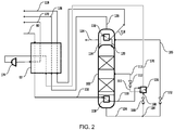
- FIG. 2 depicts an improved process over FIG. 1 .
- Common features have been given the same reference numerals. The following is a discussion of the new features.
- FIG. 2 depicts a process according to the invention where stream 100 is gaseous or two phase.
- the feed is fully, or almost fully, condensed in heat exchanger 136 which is cooled by boiling a stream 168 of helium-free bottoms liquid at elevated pressure.
- a portion 164 of the bottoms liquid is expanded across valve 166 and fed as stream 168 to the heat exchanger 136 to form stream 170 of vaporized bottoms liquid.
- Additional refrigeration is provided by expanding stream 170 in expander 174 and using the expanded stream to help cool the feed 90 in the main heat exchanger 92.
- a stream 172 of warmed nitrogen gas is then removed from the heat exchanger and may be purified.
- An advantage of the process of FIG. 2 over the comparative process depicted in FIG. 1 is that because of the additional condensation of the feed in heat exchanger 136, the vapor part of the feed and therefore the vapor flow in the column 102 above the feed location is reduced significantly leading to a reduction in the diameter of that section of the column.
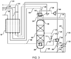
- FIG. 3 depicts an improved process over FIG. 2 .
- Common features have been given the same reference numerals. The following is a discussion of the new features.
- a further portion 132 of helium-free bottoms liquid is expanded across valve 133 and the expanded stream 134 is fed to the overhead condenser 116 where it is boiled and superheated at an intermediate pressure.
- Stream 138 of vaporized bottoms liquid is expanded in expander 140 and the expanded stream 142 and reheated in condenser 116 to produce a stream 144 of reheated nitrogen gas which is used to help cool the feed 90 in the main heat exchanger 92.
- Stream 146 of the resultant nitrogen gas is taken from the heat exchanger 92 and is available as a product or for further purification.
- Stream 170 is used without expansion to cool the feed 90 in the main heat exchanger 92.
- An advantage of the process of FIG. 3 over the process depicted in FIG. 2 is that refrigeration is integrated with the separation process, and the amount of product available at pressure is increased.
- FIG. 4 depicts a modified process of FIG. 3 in which the feed pressure is greater. Common features have been given the same reference numerals. The following is a discussion of the new features.
- Stream 164 of helium-free bottoms liquid is pumped in pump 165 to produce a stream 168 of pumped bottoms liquid which is used to cool the feed in heat exchanger 169 upstream of the column reboiler 108.
- the refrigeration provided by the expander 140 offsets the energy input to the process of the pump 168.
- FIG. 5 depicts a preferred process in which most of the nitrogen product is boiled and expanded to provide refrigeration for production of some of the nitrogen product as liquid.
- Feed 90 is cooled initially by indirect heat exchange in the main heat exchanger 92 to produce stream 100 and then subsequently further cooled and condensed by indirect heat exchange in the column reboiler 108 and heat exchanger 136.
- Stream 111 of condensed feed is expanded across valve 112 and fed to column 102 for distillation.
- the column 102 is reboiled by the feed in reboiler 108, and nitrogen in the overhead vapor is condensed in condenser 116 to provide reflux 120 for the column 102.
- a stream 118 of impure helium gas is removed from the condenser 116 and warmed against the feed 90 in the main heat exchanger 92 to produce a helium gas stream 119 suitable for purification by PSA or by some other means.
- a first portion of the helium-free bottoms liquid 104 is boiled in the bottom of column 102 to provide vapor for the column.
- a second portion 132 of helium-free bottoms liquid 104 is expanded across valve 133 and the expanded stream 134 is used to cool and condense the feed by indirect heat exchange in heat exchanger 136.
- a stream 138 of vaporized bottoms liquid is work expanded in expander 140 to produce expanded stream 142 which is then fed to the overhead condenser 116 to condense nitrogen in the overhead vapor for reflux 120.
- Stream 144 of nitrogen gas is then fed to the main heat exchanger 92 to help cool the feed 90, thereby producing a stream 146 of impure nitrogen gas suitable for further purification.
- a third portion of helium-free bottoms liquid 104 is expanded across valve 122 to produce expanded stream 105 which is fed to the overhead condenser 116 to help condense nitrogen in the overhead vapor.
- Stream 126 of nitrogen gas is then fed to the main heat exchanger 92 to help cool the feed 90, thereby produce another stream 128 of impure nitrogen gas suitable for further purification.
- a fourth portion 180 of helium-free bottoms liquid 104 is expanded across valve 182 to form a two phase stream 184 which is fed to a storage tank 185 where it is separated into a liquid stream 186 and a vapor stream 188.
- Liquid stream 186 could be vaporized to provide refrigeration, for example in a downstream helium liquefier, or exported as a product, for example for fracking.
- the vapor stream 188 is used to help cool the feed 90 in the main heat exchanger 92 to produce a further stream 190 of impure nitrogen gas suitable for further purification.
- FIG. 6 depicts a modified process of FIG. 5 in which liquid product is subcooled in condenser 116.
- Common features have been given the same reference numerals. The following is a discussion of the new features.
- the fourth portion 180 of helium-free bottoms liquid is fed without expansion to the condenser 116 where it is subcooled to form stream 181 of subcooled bottoms liquid.
- Stream 182 is expanded across valve 182 to produce expanded stream 184 which is two phase.
- Stream 184 is fed to the storage tank 185 where it is separated into the liquid stream 186 and the vapor stream 188.
- a hydrocarbon (NGL) recovery column may be added upstream of the helium separation column 102, as illustrated in FIG. 7 .
- Feed 90 is cooled in the main heat exchanger 92 and divided into a first portion 191 and a second portion.
- the first portion 191 is work expanded in expander 192 and the expanded stream 193 is fed back to the main heat exchanger 92 where it is further cooled to produce stream 194 which is fed to an intermediate location in an NGL recovery column 96.
- the second portion is further cooled and condensed by indirect heat exchange in the main heat exchanger to form stream 196 of liquid feed which is expanded across valve 94 to produce expanded feed stream 198 which is fed to the top of the NGL recovery column 96.
- the feeds to the column 96 are separated into C 2+ hydrocarbon bottoms liquid, removed as stream 199, and C 2+ hydrocarbon-depleted overhead vapor.
- Column 96 is reboiled in reboiler 98 using an external heat source such as steam, hot oil or cooling water.
- a stream 100 of overhead vapor is removed from column 96 and used to reboil the helium recovery column 102 to produce a stream 110 of cooled and partially condensed overhead vapor.
- Stream 110 is further cooled and condensed in heat exchanger 136 by indirect heat exchange against helium-free bottoms liquid 134 from column 102.
- the further condensed stream 111 is then expanded across valve 112 and fed as stream 113 to column 102 where it is separated into nitrogen-enriched bottoms liquid and helium-enriched overhead vapor.
- a stream 114 of helium-enriched overhead vapor is taken from column 102 and nitrogen in the vapor is condensed by indirect heat exchange in heat exchanger 116 to form a two phase stream 115 that is separated in phase separator 103.
- a stream 120 of nitrogen-enriched liquid is used to provide reflux to column 102.
- a stream 118 of impure helium gas is warmed by indirect heat exchange in heat exchanger 116 to form stream 121 of warmed helium gas which is then used to help cool the feed 90 by indirect heat exchange in the main heat exchanger 92.
- the stream 119 of impure helium gas from the main heat exchanger 92 is suitable for purification by PSA or by some other means.
- a first portion of the helium-free bottoms liquid 104 is boiled in the bottom of column 102 to provide vapor for the column.
- a second portion of nitrogen-enriched bottoms liquid 104 is expanded across valve 122 and the expanded stream 105 is used to provide refrigeration duty in heat exchanger 116.
- the resultant stream 126 of vaporized liquid is then used to help cool the feed 90 by indirect heat exchange in the main heat exchanger 92 to produce a stream 128 of warmed impure nitrogen gas suitable for further purification.
- a third portion 132 of the helium-free bottoms liquid 104 is expanded across valve 133 and then used to provide refrigeration duty in heat exchanger 136.
- the stream 137 of impure nitrogen gas is then removed from heat exchanger 136 and fed to the main heat exchanger 92 where is helps cool the feed 90.
- a stream 138 of warmed impure nitrogen gas is then work expanded in expander 140 and the expanded stream 142 is used to provide refrigeration duty in heat exchanger 116.
- the resultant stream 144 of impure nitrogen gas is then used to help cool the feed in the main heat exchanger 92.
- a fourth portion 180 of the helium-free bottoms liquid is subcooled in heat exchanger 116 and the resultant stream 181 is expanded across valve 182 to form a two phase stream 184 which is fed to a storage tank 185 from which a stream 186 of liquid nitrogen may be removed.
- a stream 188 of impure nitrogen gas is taken from the storage tank 185 and used to help cool the feed 90 by indirect heat exchange in the main heat exchanger 92.
- Stream 190 of warmed impure nitrogen gas is suitable for further purification.
- the helium-depleted bottoms liquid from the helium recovery column may be separated before and/or after work expansion, as illustrated in FIG. 8 .
- the feed 90 is cooled initially by indirect heat exchange in the main heat exchanger 92 and then further cooled and condensed by indirect heat exchange in the reboiler 108 of the helium recovery column 102 and heat exchanger 136.
- the condensed stream 111 is expanded across valve 112 and then fed as stream 113 to the column 102 where it is separated into helium-enriched overhead vapor and nitrogen-enriched bottoms liquid.
- Overhead vapor is removed as stream 114 and nitrogen in the stream is condensed by indirect heat exchange in heat exchanger 116 to form a two-phase stream 115 which is phase separated in phase separator 103.
- the liquid portion 120 is fed back to the top of the column 102 as reflux.
- the vapor portion 118 is used to help cool the overhead vapor in heat exchanger 116 and is then further warmed in the main exchanger 92 against the cooling feed 90.
- the resultant stream 119 of helium gas is suitable for further purification.
- a portion 132 of the bottoms liquid 104 is expanded across valve 133 and the expanded stream 134 is warmed by indirect heat exchange in heat exchanger 136 before being fed as stream 200 to a first nitrogen purification column 208.
- the feed 200 is separated into methane-enriched bottoms liquid and nitrogen-enriched overhead vapor.
- Overhead vapor 230 is condensed by indirect heat exchanger against expanded bottoms liquid 214 in overhead condenser 232 to produce reflux 234 for the column 208, and a stream 130 of liquid nitrogen.
- Stream 130 is cooled by indirect heat exchange in heat exchanger 136 and the cooled stream 180 is subcooled in heat exchanger 116.
- Subcooled stream 181 is expanded across valve 182 and the expanded stream 184 is fed to storage tank 185.
- a stream 186 of pure nitrogen liquid can be removed from tank 185. Vapor 188 from the tank is used to help cool the feed 90 in the main heat exchanger 92 to produce stream 190 of nitrogen gas.
- a stream 210 of bottoms liquid is expanded across valve 212 and the expanded stream 214 is fed to the overhead condenser for refrigeration duty.
- Vaporized bottoms liquid is removed from the overhead condenser 232 as stream 216.
- Unvaporized bottoms liquid is removed as stream 218, vaporized by indirect heat exchange in heat exchanger 136 and the vaporized stream 220 is combined with stream 216 to form combined stream 222 which is used to help cool the feed 90 in the main heat exchanger 92 and then work expanded in expander 140.
- the expanded stream 142 is then fed to a second nitrogen purification column 258 operating at a lower pressure than the first nitrogen purification column 208.
- a second portion 250 of bottoms liquid 104 from the helium recovery column 102 is subcooled by indirect heat exchange in heat exchanger 116 and the subcooled liquid 252 is expanded across valve 254 and the expanded stream 256 is fed to the top of the second nitrogen purification column.
- the feeds to the second nitrogen purification column 258 are separated into methane-enriched bottoms liquid and nitrogen-enriched overhead vapor.
- a first portion 262 of the methane-enriched bottoms liquid is reboiled in heat exchanger 116 and fed back to the column 258 to provide vapor for the distillation.
- a second portion 270 of the bottoms liquid is pumped in pump 272 and the pumped stream 274 is used to help cool the feed 90 in the main heat exchanger 92 to produce a stream 276 of fuel gas.
- a stream 226 of nitrogen vapor is warmed in heat exchangers 116 and 92 to provide a vent gas stream 146.
- FIG. 9 depicts a fully integrated scheme with NGL recovery, HP and LP columns and liquid nitrogen production from an underground gas source, and helium purification by PSA to produce a stream 302 pure helium that can be fed directly to a helium liquefier.
- Feed gas 70 from an underground source is pre-treated 72 to removed water and carbon dioxide to produce stream 90 of dry, CO 2 -free feed gas which is cooled by indirect heat exchange in the main heat exchanger 92.
- a first portion 191 of the cooled feed is expanded in expander 192 to produce a two phase stream 193 which is phase separated in separator 95.
- the liquid phase 197 is fed directly to an NGL recovery column 96.
- the vapor phase 195 is cooled in the main heat exchanger 92 and the cooled stream 194 is also fed to the NGL recovery column 96.
- a second portion of the cooled feed is further cooled in the main heat exchanger 92, expanded in valve 94 and fed to the column 96 as reflux stream 198.
- the feeds to the NGL column 96 are separated into a C 2+ -enriched bottoms liquid and C 2+ -depleted overhead vapor.
- the bottoms liquid is reboiled with external heat in reboiler 98 to provide vapor for the separation, and an NGL stream 199 is removed.
- Further vapor (stream 402) for the column 96 is provided by reboiling a stream 400 of liquid taken from an intermediate location of the column 96 in the main heat exchanger 92.
- a stream 100 of overhead vapor is cooled and condensed in the main heat exchanger 92 by indirect heat exchange against reboiling helium-free bottoms liquid 410 and expanded bottoms liquid 204 from the helium recovery column 102.
- the condensed feed 111 is then expanded across valve 112 and the expanded stream 113 fed to the helium recovery column 102 where it is separated into the helium-free bottoms liquid and helium-enriched overhead vapor.
- a stream 114 of overhead vapor is fed to the main heat exchanger 92 where nitrogen in the stream in condensed to form a two phase stream 115 which is phase separated in separator 103.
- the liquid phase 120 is fed as reflux to the helium recovery column 102.
- the vapor phase 118 is used to help cool the feed 90 in the main heat exchanger 92 and the resultant warmed stream 119 is fed to a helium PSA unit 300 which produces a stream 302 of pure helium.
- a stream 304 of tail gas from the PSA unit 300 is compressed in compressor 306 and the compressed stream 308 is cooled by indirect heat exchange in aftercooler 310 and the main heat exchanger 92 before being recycled as stream 314 to the helium recovery column 102.
- a portion of the expanded helium-free bottoms liquid is fed as stream 200 from the main heat exchanger to a first nitrogen purification column 208 where it is separated into methane-enriched bottoms liquid and nitrogen-enriched overhead vapor.
- a stream 230 of nitrogen-enriched overhead vapor is condensed by indirect heat exchange in the main heat exchanger.
- a portion 234 of the condensed stream is fed to the first nitrogen purification column as reflux.
- the remaining portion is cooled by indirect heat exchange in the main heat exchanger 92 and the cooled stream 181 expanded across valve 182 to form two phase stream 184.
- Stream 184 is fed to a storage tank 185 from which a stream 186 of liquid nitrogen may be taken.
- Vapor stream 188 is warmed in the main heat exchanger 92 to produce nitrogen gas stream 190.
- a stream 210 of methane-enriched bottoms liquid is expanded across valve 212 and expanded stream 214 is warmed and vaporized by indirect heat exchange in the main heat exchanger 92.
- Gaseous stream 138 is expanded in expander 140 and the expanded stream is fed to a second nitrogen purification column 258. Reflux to the second nitrogen purification column 258 is provided by a portion 252 of the expanded bottoms liquid 204 from the helium recovery column 102.
- Stream 252 is expanded across valve 254 and fed as reflux stream 256 to the column 258.
- the feeds to the second nitrogen purification column are separated into methane-enriched bottoms liquid and nitrogen-enriched overhead vapor.
- the column is reboiled by vaporizing a stream 260 of bottoms liquid in the main heat exchanger 92.
- a stream 270 of bottoms liquid is pumped in pump 272 and pumped stream 274 is used to help cool the feed 90 in the main heat exchanger 92 to produce fuel gas stream 276.
- a stream 226 of overhead vapor is warmed by indirect heat exchange in the main heat exchanger 92 and divided into two portions, streams 147 and 280.
- Stream 147 may be a product stream but it is usually vented.
- Stream 280 is compressed in compressor 282 and the compressed stream 284 is cooled in aftercooler 286.
- the cooled stream 288 is cooled in the main heat exchanger 92 before being combined with stream 214 after it has been vaporized to form combined stream 138 from the first nitrogen purification column 208 to the second nitrogen purification column 258.
- the power to recompress the product 128 to the feed pressure of 30 bar is 2899 kW.
- the advantage in this example is that the refrigeration is integrated with the separation process, and the amount of product available at pressure is increased - only 6.3% of the product is at low pressure. The total power consumption is also slightly reduced (by 2.1%) to 779 kW.
- part of the helium-free product 164 is increased in pressure in a pump 165 and used to cool the feed in heat exchanger 169 upstream of the column reboiler 108.
- the refrigeration provided by the expander offsets the energy input to the process in the pump.
- the total power including recompression of the products back to the feed pressure (50 bar in this case) is 757 kW.
- the feed is at 50 bar as in Example 3, but is expanded in warm expander 192 prior to separation in NGL recovery column 96.
- a small part of the high pressure feed is condensed and fed to the top of the NGL recovery column as reflux.
- This column is reboiled with an external heat source such as steam, hot oil or cooling water.
- the liquid production is higher than in Example 5 because of the higher feed pressure and additional refrigeration provided by the warm expander.
- the specific power for liquid production is also lower as the warm and cold expander system provides refrigeration more efficiently than a single expander.
- the total power including product recompression to 50 bar and net of the power generation from the expanders of 546 kW is 2864 kW. 94 tonnes per day of liquid is produced.
- Example 3 which also has a feed pressure of 50 bar
- the total power is 2107 kW higher for the production of 94 tonnes per day liquid, meaning that the specific power for the liquid production is 537 kWh/t.
- the total power including product recompression to 30 bar and net of the power generation from the expander of 354 kW is 2515 kW. 70 tonnes per day of liquid is produced. Compared to Example 2, the total power is 1736 kW higher for the production of 70 tonnes per day liquid, meaning that the specific power for the liquid production is 596 kWh/t.
- the total power including recycle and tail gas compression as well as product recompression to 50 bar and net of the power generation from the expanders of 552 kW is 3550 kW. 100 tonnes per day of liquid is produced. Compared to Example 3 (which also has a feed pressure of 50 bar), the total power is 2793 kW higher for the production of 100 tonnes per day liquid, meaning that the specific power for the liquid production is 670 kWh/t.
Landscapes
- Engineering & Computer Science (AREA)
- Physics & Mathematics (AREA)
- Mechanical Engineering (AREA)
- Thermal Sciences (AREA)
- General Engineering & Computer Science (AREA)
- Chemical & Material Sciences (AREA)
- Chemical Kinetics & Catalysis (AREA)
- General Chemical & Material Sciences (AREA)
- Oil, Petroleum & Natural Gas (AREA)
- Separation By Low-Temperature Treatments (AREA)
Applications Claiming Priority (1)
| Application Number | Priority Date | Filing Date | Title |
|---|---|---|---|
| US15/041,359 US10215488B2 (en) | 2016-02-11 | 2016-02-11 | Treatment of nitrogen-rich natural gas streams |
Publications (1)
| Publication Number | Publication Date |
|---|---|
| EP3205962A1 true EP3205962A1 (fr) | 2017-08-16 |
Family
ID=58009762
Family Applications (1)
| Application Number | Title | Priority Date | Filing Date |
|---|---|---|---|
| EP17155467.8A Withdrawn EP3205962A1 (fr) | 2016-02-11 | 2017-02-09 | Traitement de flux de gaz naturel riche en azote |
Country Status (5)
| Country | Link |
|---|---|
| US (1) | US10215488B2 (fr) |
| EP (1) | EP3205962A1 (fr) |
| AP (1) | AP2017009739A0 (fr) |
| CA (1) | CA2957140C (fr) |
| ZA (1) | ZA201700894B (fr) |
Cited By (3)
| Publication number | Priority date | Publication date | Assignee | Title |
|---|---|---|---|---|
| CN110455038A (zh) * | 2019-08-22 | 2019-11-15 | 北京中科富海低温科技有限公司 | 一种氦提取单元、氦提取装置和联产氦气的系统 |
| WO2022018669A1 (fr) * | 2020-07-22 | 2022-01-27 | 8 Rivers Capital, Llc | Séparation de dioxyde de carbone et de matériaux sulfureux de mélanges gazeux |
| RU2844226C1 (ru) * | 2024-03-13 | 2025-07-28 | Общество с ограниченной ответственностью научно-исследовательский и проектный институт "ПЕГАЗ" | Блок выделения концентрата гелия из отпарного газа |
Families Citing this family (14)
| Publication number | Priority date | Publication date | Assignee | Title |
|---|---|---|---|---|
| US10072890B2 (en) | 2016-03-21 | 2018-09-11 | Praxair Technology, Inc. | System and method for enhanced argon recovery from a feed stream comprising hydrogen, methane, nitrogen and argon |
| US10309720B2 (en) * | 2016-03-21 | 2019-06-04 | Praxair Technology, Inc. | System and method for argon recovery from a feed stream comprising hydrogen, methane, nitrogen and argon |
| CN107514872B (zh) * | 2017-09-27 | 2022-11-25 | 中科瑞奥能源科技股份有限公司 | 从lng储罐闪蒸汽中回收氦气的工艺与系统 |
| MY195957A (en) * | 2019-03-11 | 2023-02-27 | Uop Llc | Hydrocarbon Gas Processing |
| FR3096900B1 (fr) * | 2019-06-06 | 2021-10-01 | Air Liquide | Procédé et unité de purification d’hélium |
| WO2021092546A1 (fr) * | 2019-11-07 | 2021-05-14 | Conocophillips Company | Systèmes et procédés d'élimination de l'azote pendant la liquéfaction de gaz naturel |
| CN111156789B (zh) * | 2020-02-25 | 2024-12-10 | 成都赛普瑞兴科技有限公司 | 含氮甲烷气脱氮设备 |
| CN111895724A (zh) * | 2020-07-01 | 2020-11-06 | 陕西裕隆气体有限公司 | 一种二氧化碳脱水方法 |
| CN111981767B (zh) * | 2020-08-20 | 2024-03-08 | 中国石油工程建设有限公司 | 一种天然气单塔深冷提氦装置和方法 |
| CN113959176B (zh) * | 2021-10-20 | 2023-06-16 | 北京石油化工工程有限公司 | 一种液化天然气闪蒸气中氦气的分离系统和方法 |
| CN114087845B (zh) * | 2021-11-19 | 2022-07-15 | 北京大臻科技有限公司 | 一种基于仲氢循环的液氢生产装置、系统及方法 |
| CN115854655B (zh) * | 2023-01-05 | 2025-03-07 | 江苏宏仁特种气体有限公司 | 一种高纯低温液态气体安全生产装置及方法 |
| CN116067121B (zh) * | 2023-01-12 | 2024-10-22 | 西南石油大学 | 一种低含氦天然气多级浓缩提氦联产lng的方法 |
| CN117053499B (zh) * | 2023-08-15 | 2025-04-11 | 广东九丰特种气体有限公司 | 一种基于侧线采出的天然气分离方法 |
Citations (5)
| Publication number | Priority date | Publication date | Assignee | Title |
|---|---|---|---|---|
| US3205669A (en) * | 1960-08-15 | 1965-09-14 | Phillips Petroleum Co | Recovery of natural gas liquids, helium concentrate, and pure nitrogen |
| US3531943A (en) | 1965-10-23 | 1970-10-06 | Aerojet General Co | Cryogenic process for separation of a natural gas with a high nitrogen content |
| US4701200A (en) * | 1986-09-24 | 1987-10-20 | Union Carbide Corporation | Process to produce helium gas |
| CA1230821A (fr) * | 1984-01-13 | 1987-12-29 | Ravindra F. Pahade | Methode de separation des liquides du gaz naturel contenant de l'azote |
| US5167125A (en) | 1991-04-08 | 1992-12-01 | Air Products And Chemicals, Inc. | Recovery of dissolved light gases from a liquid stream |
Family Cites Families (20)
| Publication number | Priority date | Publication date | Assignee | Title |
|---|---|---|---|---|
| US1529625A (en) | 1923-06-15 | 1925-03-10 | Carbide & Carbon Chem Corp | Process of recovering helium |
| DE620077C (de) | 1934-03-23 | 1935-10-14 | Linde Eismasch Ag | Verfahren zur Zerlegung von Gasgemischen |
| US3181307A (en) | 1960-02-16 | 1965-05-04 | Phillips Petroleum Co | Helium separation |
| FR1360323A (fr) | 1963-03-28 | 1964-05-08 | Air Liquide | Procédé de séparation d'hélium d'un mélange gazeux |
| US3815376A (en) | 1969-07-31 | 1974-06-11 | Airco Inc | Process and system for the production and purification of helium |
| DE2022954C3 (de) | 1970-05-12 | 1978-05-18 | Linde Ag, 6200 Wiesbaden | Verfahren zur Zerlegung von stickstoffhaltigem Erdgas |
| US3740962A (en) | 1970-09-18 | 1973-06-26 | Commw Ass Inc | Process of and apparatus for the recovery of helium from a natural gas stream |
| US4195979A (en) | 1978-05-12 | 1980-04-01 | Phillips Petroleum Company | Liquefaction of high pressure gas |
| US4701201A (en) * | 1986-09-24 | 1987-10-20 | Union Carbide Corporation | Process to produce cold helium gas for liquefaction |
| US4878932A (en) * | 1989-03-21 | 1989-11-07 | Union Carbide Corporation | Cryogenic rectification process for separating nitrogen and methane |
| US4948404A (en) | 1989-08-03 | 1990-08-14 | Phillips Petroleum Company | Liquid nitrogen by-product production in an NGL plant |
| US5011521A (en) | 1990-01-25 | 1991-04-30 | Air Products And Chemicals, Inc. | Low pressure stripping process for production of crude helium |
| US5041149A (en) | 1990-10-18 | 1991-08-20 | Union Carbide Industrial Gases Technology Corporation | Separation of nitrogen and methane with residue turboexpansion |
| US5339641A (en) | 1993-07-07 | 1994-08-23 | Praxair Technology, Inc. | Cryogenic liquid nitrogen production system |
| US5771714A (en) | 1997-08-01 | 1998-06-30 | Praxair Technology, Inc. | Cryogenic rectification system for producing higher purity helium |
| FR2772896B1 (fr) | 1997-12-22 | 2000-01-28 | Inst Francais Du Petrole | Procede de liquefaction d'un gaz notamment un gaz naturel ou air comportant une purge a moyenne pression et son application |
| FR2832213B1 (fr) | 2001-11-12 | 2004-09-24 | Air Liquide | Procede et installation de production d'helium |
| DE102005006408A1 (de) * | 2005-02-11 | 2006-08-24 | Linde Ag | Verfahren zum Abtrennen von Spurenkomponenten aus einem Stickstoff-reichen Strom |
| FR2936864B1 (fr) | 2008-10-07 | 2010-11-26 | Technip France | Procede de production de courants d'azote liquide et gazeux, d'un courant gazeux riche en helium et d'un courant d'hydrocarbures deazote et installation associee. |
| US20140137599A1 (en) | 2011-07-22 | 2014-05-22 | Russell H. Oelfke | Helium Recovery From Natural Gas Streams |
-
2016
- 2016-02-11 US US15/041,359 patent/US10215488B2/en active Active
-
2017
- 2017-02-03 ZA ZA2017/00894A patent/ZA201700894B/en unknown
- 2017-02-06 CA CA2957140A patent/CA2957140C/fr active Active
- 2017-02-07 AP AP2017009739A patent/AP2017009739A0/en unknown
- 2017-02-09 EP EP17155467.8A patent/EP3205962A1/fr not_active Withdrawn
Patent Citations (5)
| Publication number | Priority date | Publication date | Assignee | Title |
|---|---|---|---|---|
| US3205669A (en) * | 1960-08-15 | 1965-09-14 | Phillips Petroleum Co | Recovery of natural gas liquids, helium concentrate, and pure nitrogen |
| US3531943A (en) | 1965-10-23 | 1970-10-06 | Aerojet General Co | Cryogenic process for separation of a natural gas with a high nitrogen content |
| CA1230821A (fr) * | 1984-01-13 | 1987-12-29 | Ravindra F. Pahade | Methode de separation des liquides du gaz naturel contenant de l'azote |
| US4701200A (en) * | 1986-09-24 | 1987-10-20 | Union Carbide Corporation | Process to produce helium gas |
| US5167125A (en) | 1991-04-08 | 1992-12-01 | Air Products And Chemicals, Inc. | Recovery of dissolved light gases from a liquid stream |
Non-Patent Citations (1)
| Title |
|---|
| HANDLEY J R ET AL: "PROCESS REQUIREMENTS AND ENHANCED ECONOMICS OF HELIUM RECOVERY FROM NATURAL GAS", SPE MID-CONTINENT GAS SYMPO, XX, XX, no. SPE24292, 12 April 1992 (1992-04-12), pages 11, XP009067940 * |
Cited By (4)
| Publication number | Priority date | Publication date | Assignee | Title |
|---|---|---|---|---|
| CN110455038A (zh) * | 2019-08-22 | 2019-11-15 | 北京中科富海低温科技有限公司 | 一种氦提取单元、氦提取装置和联产氦气的系统 |
| CN110455038B (zh) * | 2019-08-22 | 2021-06-15 | 北京中科富海低温科技有限公司 | 一种氦提取单元、氦提取装置和联产氦气的系统 |
| WO2022018669A1 (fr) * | 2020-07-22 | 2022-01-27 | 8 Rivers Capital, Llc | Séparation de dioxyde de carbone et de matériaux sulfureux de mélanges gazeux |
| RU2844226C1 (ru) * | 2024-03-13 | 2025-07-28 | Общество с ограниченной ответственностью научно-исследовательский и проектный институт "ПЕГАЗ" | Блок выделения концентрата гелия из отпарного газа |
Also Published As
| Publication number | Publication date |
|---|---|
| US20170234612A1 (en) | 2017-08-17 |
| CA2957140A1 (fr) | 2017-08-11 |
| US10215488B2 (en) | 2019-02-26 |
| CA2957140C (fr) | 2020-04-14 |
| AP2017009739A0 (en) | 2017-02-28 |
| ZA201700894B (en) | 2018-11-28 |
Similar Documents
| Publication | Publication Date | Title |
|---|---|---|
| US10215488B2 (en) | Treatment of nitrogen-rich natural gas streams | |
| CA3054907C (fr) | Extraction d`helium a partir de gaz naturel | |
| JP4230956B2 (ja) | 天然ガスからのメタンより重い成分回収方法及び装置 | |
| JP5710137B2 (ja) | 等圧開放冷凍天然ガス液回収による窒素除去 | |
| CA2440142C (fr) | Processus cryogenique utilisant une colonne absorbante a haute pression | |
| AU2007203296B2 (en) | Integrated NGL recovery in the production of liquefied natural gas | |
| JP4216765B2 (ja) | 凝縮天然ガスからの窒素除去方法及び装置 | |
| EP2865976B1 (fr) | Purification de dioxyde de carbone | |
| CA2813434C (fr) | Purification de dioxyde de carbone | |
| JP2008545819A (ja) | 統合されたnglの回収および液化天然ガスの製造 | |
| AU2002338248A1 (en) | Cryogenic process utilizing high pressure absorber column | |
| NO158478B (no) | Fremgangsmaate for separering av nitrogen fra naturgass. | |
| US20190041128A1 (en) | Recovery Of Helium From Nitrogen-Rich Streams | |
| CA3097220C (fr) | Retrait des gaz legers du dioxyde de carbone | |
| EP3052586B1 (fr) | Récupération de gpl par réfrigération ouverte par introduction simultanée à pression constante | |
| AU2018392161A1 (en) | Method for liquefying a natural gas stream containing nitrogen |
Legal Events
| Date | Code | Title | Description |
|---|---|---|---|
| PUAI | Public reference made under article 153(3) epc to a published international application that has entered the european phase |
Free format text: ORIGINAL CODE: 0009012 |
|
| AK | Designated contracting states |
Kind code of ref document: A1 Designated state(s): AL AT BE BG CH CY CZ DE DK EE ES FI FR GB GR HR HU IE IS IT LI LT LU LV MC MK MT NL NO PL PT RO RS SE SI SK SM TR |
|
| AX | Request for extension of the european patent |
Extension state: BA ME |
|
| 17P | Request for examination filed |
Effective date: 20180216 |
|
| RBV | Designated contracting states (corrected) |
Designated state(s): AL AT BE BG CH CY CZ DE DK EE ES FI FR GB GR HR HU IE IS IT LI LT LU LV MC MK MT NL NO PL PT RO RS SE SI SK SM TR |
|
| 17Q | First examination report despatched |
Effective date: 20190821 |
|
| STAA | Information on the status of an ep patent application or granted ep patent |
Free format text: STATUS: THE APPLICATION IS DEEMED TO BE WITHDRAWN |
|
| 18D | Application deemed to be withdrawn |
Effective date: 20200303 |