EP3205970B1 - Arme à canon basculant - Google Patents
Arme à canon basculant Download PDFInfo
- Publication number
- EP3205970B1 EP3205970B1 EP16204146.1A EP16204146A EP3205970B1 EP 3205970 B1 EP3205970 B1 EP 3205970B1 EP 16204146 A EP16204146 A EP 16204146A EP 3205970 B1 EP3205970 B1 EP 3205970B1
- Authority
- EP
- European Patent Office
- Prior art keywords
- break
- mounting
- weapon according
- action weapon
- clamping element
- Prior art date
- Legal status (The legal status is an assumption and is not a legal conclusion. Google has not performed a legal analysis and makes no representation as to the accuracy of the status listed.)
- Active
Links
Images


Classifications
-
- F—MECHANICAL ENGINEERING; LIGHTING; HEATING; WEAPONS; BLASTING
- F41—WEAPONS
- F41A—FUNCTIONAL FEATURES OR DETAILS COMMON TO BOTH SMALLARMS AND ORDNANCE, e.g. CANNONS; MOUNTINGS FOR SMALLARMS OR ORDNANCE
- F41A3/00—Breech mechanisms, e.g. locks
- F41A3/58—Breakdown breech mechanisms, e.g. for shotguns
-
- F—MECHANICAL ENGINEERING; LIGHTING; HEATING; WEAPONS; BLASTING
- F41—WEAPONS
- F41C—SMALLARMS, e.g. PISTOLS, RIFLES; ACCESSORIES THEREFOR
- F41C7/00—Shoulder-fired smallarms, e.g. rifles, carbines, shotguns
- F41C7/11—Breakdown shotguns or rifles
Definitions
- the invention relates to a dumping weapon according to the preamble of claim 1.
- Kipplaufwaffe is from the US 2006/0070289 A1 known.
- This has a system box or a closure housing, a rotatable about an axis of rotation on the closure housing arranged Laufteil, removably attached to the barrel part forearm and seen in the weft direction of Kipplaufwaffe arranged at the rear end of the forearm bearing piece for pivotal contact with the closure housing.
- the bearing piece disposed at the rear end of the fore-end includes rear bearing surfaces for pivotally abutting mating front mating surfaces of the closure housing.
- the tilting weapon For adjusting the position of the bearing piece relative to the running part, the tilting weapon comprises a positioning device which comprises a displaceably guided in the bearing piece in the longitudinal direction of the forend and guided by an adjusting clamping piece for abutment with a arranged on the running part stop.
- the block-shaped clamping piece is slidably guided in an upwardly open receiving groove of a forwardly projecting lug of the bearing piece.
- the object of the invention is to provide a Kipplaufwaffe of the aforementioned type which allows a simple and accurate adjustment or adjustment of the hinge passage between the closure housing and the tiltable running part.
- the receiving groove in the form of a T-groove with a running part facing the narrower outer part and a widened inner part is executed.
- the associated clamping piece has the shape of a T-slot nut with a narrower upper part and a wider lower part.
- the receiving groove has a slightly greater width than the clamping piece, so that the clamping piece within the receiving groove not only displaced in the direction of a longitudinal axis of the receiving groove extending in the longitudinal direction of the front shaft, but also slightly rotated about an axis perpendicular to this longitudinal axis.
- a front bearing surface of the clamping piece can be easily tilted and adapted to the stop surface of the associated stop without consuming manual rework.
- the clamping piece has a continuous threaded bore with a threaded pin arranged therein. By screwing the threaded pin, the clamping piece can be clamped against the bearing part and thereby secured in a set position.
- the actuator can also be arranged in the receiving groove for the clamping piece.
- the actuator can be designed as a Sachxzenter with a rotatably guided in the narrower outer part of the receiving groove cylindrical part and arranged in the widened inner part of the receiving groove eccentric part.
- the actuator may have a continuous threaded bore with a threaded pin disposed therein to prevent rotation.
- the central axis of the threaded bore relative to the central axis of the receiving groove is laterally offset. As a result, an undesirable adjustment can be avoided particularly well.
- Partial illustrated Kipplaufwaffe contains a system box shown only partially or a closure housing 1, a forearm 2 and on the closure housing 1 about a transverse axis 3 tiltable and removable arranged Laufteil 4, which in the embodiment shown in FIG. 3 separately shown hook piece 5, two superposed barrels 6 and 7 and a sighting rail 8 includes.
- the forearm 2 has at its seen in the weft direction front end of a not recognizable here locking mechanism for releasably supporting the forearm 2 on the lower barrel 7 of the barrel part 4 and at its rear end in FIG. 2 separately shown bearing piece 9 to rest on the closure housing 1 on.
- a rear shaft not shown here, is fastened in a manner known per se.
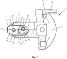
- FIG. 2 shown in a plan view in half section and made of metal bearing piece 9 includes a rear contact part 10 and a forwardly projecting lug 11, which in an in FIG. 1 shown recess 12 is arranged at the rear end of the forearm 2.
- the in a rear view U-shaped rear part of the system 10 has two hook piece 5 cross-side webs 13, the rear side concave rear bearing surfaces 14 for abutment thereon corresponding - in FIG. 1 have shown - convex mating surfaces 15 at the front end of the closure housing 1.
- two end holes 16 are provided for fastening the bearing piece 9 on the forearm 2.
- closure housing 1 For tiltable arrangement of the running part 4 on the closure housing 1 about the rotation axis 3 are on two opposite edges of in FIG. 1 shown closure housing 1 inwardly projecting hinge pin 17, which in lateral recesses 18 on the two side surfaces 19 of the in FIG. 3 hook piece 5 shown engage.
- the two forwardly open, lateral recesses 18 each have a semicircular rear abutment surface 20, where the hinge bolt 17 projecting inwardly from the closure housing 1 come into abutment.
- the hook-shaped piece 5 includes on its underside a running hook 21 which engages in a corresponding receiving opening of the closure housing 1 and by a in a locking slot 22 at the back of the Running hook 21 engaging locking wedge locked or can be released to tilt the barrel part 4.
- the pressing of the hook piece 5 against the hinge pin 17 via the attached to the rear end of the forearm 2 bearing piece 9, according to FIG. 1 on the one hand is supported by a control element 23 adjustable clamping piece 24 to a stop 25 on the lower barrel of the running part 4 and on the other hand presses with the concave bearing surfaces 14 on the side bars 13 against the convex mating surfaces 15 on the two side surfaces of the closure housing 1.
- the stop 25 provided with a rear abutment surface 26 is designed as a separate component, which is fastened to the lower run 7, for example by soldering.
- the stop 25 can also be integrated on the barrel or formed integrally therewith.
- the clamping piece 24 is guided in a receiving groove 27 of the bearing part 9 in the longitudinal direction of the forearm 2 slidably.
- the upwardly and forwardly open receiving groove 27 is located in the forwardly projecting lug 11 of the bearing part 9 and is in the form of a T-groove with the running part 4 facing narrow outer part 28 and a widened inner part 29 executed.
- the clamping piece 24 is designed in the form of a T-slot nut with a narrower upper part 30 and a wider lower part 31. It has a front abutment surface 32 for abutment with the abutment surface 26 of the abutment 25 and a rear abutment surface 33 for the actuating element 23.
- the receiving groove 27 has a slightly greater width than and the guided therein clamping piece 24, so that the clamping piece 24 is displaced within the receiving groove 27 not only in the direction of a longitudinal axis of the forearm 2 extending longitudinal axis 34 of the receiving groove 27, but one to this longitudinal axis 34 vertical axis to the side can also be easily twisted.
- the clamping piece 24 can be arranged so that its longitudinal axis 35 assumes an angle to the central axis 34 of the recess 27.
- the front abutment surface 32 can be easily tilted and adapted to the stop surface 26 of the stopper 25 without laborious manual reworking.
- a threaded pin 37 is arranged, through which the clamping piece 24 can be clamped against the bearing part 9. As a result, a previously set position of the clamping piece 24 can be secured.
- the adjusting element 23 for adjusting the clamping piece 24 is executed in the embodiment shown as a setting eccentric with a rotatably guided in the narrower outer part 28 of the receiving groove 27 cylindrical portion 38 and in the widened inner part 29 of the receiving groove 27 arranged eccentric part 39.
- the clamping piece 24 can be moved over the eccentric portion 39 of the actuating element 23.
- Also in the adjusting element 23 is provided for preventing rotation in a threaded bore 40 threaded pin 41.
- the central axis of the threaded bore 40 is offset laterally relative to the central axis 34 of the receiving groove 27.
- the clamping piece 24 By adjusting the clamping piece 24, the position of the arranged at the back of the forearm 2 bearing part 9 relative to the running part 4 and its hook piece 5 and thus changed the contact pressure between the hinge pin 7 and the rear abutment surfaces 20 on the hook piece 5 on the one hand and the contact pressure be set between the concave bearing surfaces 14 on the bearing part 9 and the corresponding mating surfaces 15 on the closure housing 1 on the other hand.
- the hinge between the closure housing 1 and the tiltable running part 4 is adjustable in a simple and accurate manner.
- the hook piece 5 When assembling the Kipplaufwaffe described above, the hook piece 5 is first used with the two runs 6 and 7 and the sighting rail 8 on the closure housing 1, that the hook piece 5 comes with its two contact surfaces 20 from behind to rest on the two hinge pin 17. Then the front shaft 2, which is still tilted downwards at its front side, can be attached to the closure housing 1 with its rear bearing piece 9 such that the rear bearing surfaces 14 provided on the side webs 13 of the bearing piece 9 come into abutment against the associated mating surfaces 15 of the closure housing 1. Then the forearm 2 can also be pivoted upwards on its front side, so that the tensioning piece 24 comes into contact with the stop 25 and the forearm 2 is held locked on its front side by the locking mechanism (not illustrated here) on the lower running part 7.
- the contact pressure of the bearing part 9 can be changed against the closure housing 1 and thereby the hinge gear can be adjusted.
- the two can Threaded screws are tightened so that the desired position of the clamping piece 24 secured and unwanted rotation of the actuating element 23 can be avoided.
Landscapes
- Engineering & Computer Science (AREA)
- General Engineering & Computer Science (AREA)
- Aiming, Guidance, Guns With A Light Source, Armor, Camouflage, And Targets (AREA)
- Pivots And Pivotal Connections (AREA)
- Clamps And Clips (AREA)
- Hinges (AREA)
- Toys (AREA)
Claims (10)
- Arme à canon basculant avec un boîtier de culasse (1), une partie de canon (4) disposée de manière à pouvoir basculer autour d'un axe de rotation (3) au niveau du boîtier de culasse (1), une crosse avant (2) fixée de manière à pouvoir être retirée au niveau de la partie de canon et une pièce formant palier (9) disposée, dans une vue dans la direction de tir de l'arme à canon basculant, au niveau de l'extrémité arrière de la crosse avant (2), qui comprend des surfaces de palier (14) arrière destinées à venir en appui de manière à pouvoir pivoter au niveau de faces complémentaires (15) avant du boîtier de culasse (1) et un dispositif de positionnement servant à régler la position de la pièce formant palier (9) par rapport à la partie de canon (4), dans laquelle le dispositif de positionnement comprend une pièce de serrage (24) guidée de manière à pouvoir être coulissée dans la pièce formant palier (9) dans la direction longitudinale de la crosse avant (2) et pouvant être ajustée par un élément de réglage (23), destinée à venir en appui au niveau d'une butée (25) disposée au niveau de la partie de canon (4) et dans laquelle la pièce de serrage (24) est guidée de manière à pouvoir coulisser dans une rainure de logement (27) ouverte vers le haut et vers l'avant d'un épaulement (11), faisant saillie vers l'avant, de la pièce formant palier (9), caractérisée en ce que la rainure de logement (27) est réalisée sous la forme d'une rainure en T avec une partie extérieure (28) plus étroite tournée vers la partie de canon (4) et une partie intérieure (29) élargie, et la pièce de serrage (24), sous la forme d'un coulisseau en T avec une partie supérieure (30) plus étroite et une partie inférieure (31) plus large.
- Arme à canon basculant selon la revendication 1, caractérisée en ce que la rainure de logement (27) présente une largeur légèrement plus grande que la pièce de serrage (24) guidée dans celle-ci.
- Arme à canon basculant selon la revendication 1 ou 2, caractérisée en ce que la pièce de serrage (24) contient une surface de butée avant (32) destinée à venir en appui au niveau d'une surface de butée arrière (26) de la butée (25).
- Arme à canon basculant selon l'une quelconque des revendications 1 à 3, caractérisée en ce que la pièce de serrage (24) contient un alésage fileté (36) continu avec une tige filetée (37) disposée dans celui-ci.
- Arme à canon basculant selon l'une quelconque des revendications 1 à 4, caractérisée en ce que l'élément de réglage (23) est disposé dans la rainure de logement (27) pour la pièce de serrage (24).
- Arme à canon basculant selon l'une quelconque des revendications 1 à 5, caractérisée en ce que l'élément de réglage (23) est réalisé en tant qu'excentrique de réglage avec une partie cylindrique (38) guidée de manière à pouvoir tourner dans la partie extérieure (28) plus étroite de la rainure de logement (27) et une partie excentrique (39) disposée dans la partie intérieure (29) élargie de la rainure de logement (27).
- Arme à canon basculant selon l'une quelconque des revendications 1 à 6, caractérisée en ce que l'élément de réglage (23) contient un alésage fileté (40) continu avec une tige filetée (41) disposée dans celui-ci.
- Arme à canon basculant selon la revendication 7, caractérisée en ce que l'axe médian de l'alésage fileté (40) dans l'élément de réglage (23) est décalé de manière latérale par rapport à l'axe médian (34) de la rainure de logement (27).
- Arme à canon basculant selon l'une quelconque des revendications 1 à 8, caractérisée en ce que le boîtier de culasse (1) contient des boulons de charnière (17) dépassant vers l'intérieur destinés à venir en prise avec des évidements (18) latéraux au niveau d'une pièce formant crochet (5) de la partie de canon (4).
- Arme à canon basculant selon la revendication 9, caractérisée en ce que les évidements (18) latéraux présentent des surfaces d'appui (20) arrière pour les boulons de charnière (17).
Applications Claiming Priority (1)
| Application Number | Priority Date | Filing Date | Title |
|---|---|---|---|
| DE102016102403.1A DE102016102403B4 (de) | 2016-02-11 | 2016-02-11 | Kipplaufwaffe |
Publications (2)
| Publication Number | Publication Date |
|---|---|
| EP3205970A1 EP3205970A1 (fr) | 2017-08-16 |
| EP3205970B1 true EP3205970B1 (fr) | 2018-10-17 |
Family
ID=57590327
Family Applications (1)
| Application Number | Title | Priority Date | Filing Date |
|---|---|---|---|
| EP16204146.1A Active EP3205970B1 (fr) | 2016-02-11 | 2016-12-14 | Arme à canon basculant |
Country Status (6)
| Country | Link |
|---|---|
| US (1) | US9982957B2 (fr) |
| EP (1) | EP3205970B1 (fr) |
| DE (1) | DE102016102403B4 (fr) |
| DK (1) | DK3205970T3 (fr) |
| ES (1) | ES2704576T3 (fr) |
| RU (1) | RU2712402C2 (fr) |
Families Citing this family (1)
| Publication number | Priority date | Publication date | Assignee | Title |
|---|---|---|---|---|
| RU2715819C1 (ru) * | 2019-09-10 | 2020-03-03 | Максим Сергеевич Турлаков | Винтовка турлакова n 6 (разборная) |
Family Cites Families (19)
| Publication number | Priority date | Publication date | Assignee | Title |
|---|---|---|---|---|
| US1029374A (en) * | 1912-06-11 | J C Kremer | Fore arm lock for guns. | |
| US241466A (en) * | 1881-05-10 | wilson | ||
| US1797320A (en) * | 1930-03-21 | 1931-03-24 | Winchester Repeating Arms Co | Adjustable locking mechanism for breakdown firearms |
| FR2155160A5 (fr) * | 1971-10-08 | 1973-05-18 | St Etienne Manuf Armes | |
| FR2325893A1 (fr) * | 1975-09-26 | 1977-04-22 | Verney Carron Sa | Fusil de chasse a canons juxtaposes |
| SU937973A1 (ru) * | 1980-11-18 | 1982-06-23 | Предприятие П/Я Г-4406 | Запирающий механизм ружь с откидными стволами |
| US4964232A (en) * | 1989-08-30 | 1990-10-23 | U. S. Competition Arms, Inc. | Single barrel break-action trap shotgun |
| FR2701098B1 (fr) * | 1993-01-29 | 1995-04-21 | Demas Ets | Dispositif de calage frette-bascule dans un fusil de chasse à canons juxtaposés. |
| DE4422895C1 (de) * | 1994-06-30 | 1995-10-12 | Blaser Horst Jagdwaffen | Vorderschafthalterung für eine Kipplaufwaffe |
| ITMI970419A1 (it) * | 1997-02-26 | 1998-08-27 | Franchi S P A | Fucile da caccia a canne sovrapposte con dispositivo per la intercambiabilita' di serie del gruppo canne |
| FR2760830B1 (fr) * | 1997-03-11 | 1999-06-11 | Demas Ets | Dispositif de calage anti recul de la frette ou planche a bascule d'un fusil de chasse |
| DE19909114C1 (de) | 1999-03-03 | 2000-10-05 | Blaser Horst Jagdwaffen | Vorderschafthalterung |
| US6470617B1 (en) * | 2001-10-31 | 2002-10-29 | Thomas M. Gregory | Folding stock |
| DE10235283C1 (de) * | 2002-08-02 | 2003-12-18 | Sat Swiss Arms Technology Ag | Kipplaufwaffe |
| DE10241764A1 (de) * | 2002-09-10 | 2004-03-18 | Manfred Orth | Gewehr, umfassend einen Hinterschaft und ein Gehäuse mit einer Gehäusehülse |
| ITMI20041892A1 (it) | 2004-10-06 | 2005-01-06 | Beretta Armi Spa | Dispositivo di regolazione del tiraggio tra croce e bascula in una arma basculante |
| ITMI20062231A1 (it) * | 2006-11-22 | 2008-05-23 | Beretta Armi Spa | Fucile sovrapposto basculante dotato di dispositivo di estrazione selettiva controllata di bossoli |
| DE102008006200A1 (de) * | 2008-01-26 | 2009-07-30 | Blaser Finanzholding Gmbh | Laufbündel einer Handfeuerwaffe |
| TR201815581T4 (tr) * | 2014-01-02 | 2018-11-21 | Caesar Guerini S R L | Kırmalı ateşli silah. |
-
2016
- 2016-02-11 DE DE102016102403.1A patent/DE102016102403B4/de not_active Expired - Fee Related
- 2016-12-14 ES ES16204146T patent/ES2704576T3/es active Active
- 2016-12-14 EP EP16204146.1A patent/EP3205970B1/fr active Active
- 2016-12-14 DK DK16204146.1T patent/DK3205970T3/en active
-
2017
- 2017-02-07 RU RU2017103949A patent/RU2712402C2/ru active
- 2017-02-08 US US15/427,239 patent/US9982957B2/en active Active
Non-Patent Citations (1)
| Title |
|---|
| None * |
Also Published As
| Publication number | Publication date |
|---|---|
| US20170234633A1 (en) | 2017-08-17 |
| ES2704576T3 (es) | 2019-03-18 |
| DE102016102403A1 (de) | 2017-08-17 |
| US9982957B2 (en) | 2018-05-29 |
| RU2017103949A3 (fr) | 2019-11-28 |
| RU2712402C2 (ru) | 2020-01-28 |
| EP3205970A1 (fr) | 2017-08-16 |
| DK3205970T3 (en) | 2019-02-04 |
| RU2017103949A (ru) | 2018-08-10 |
| DE102016102403B4 (de) | 2019-08-01 |
Similar Documents
| Publication | Publication Date | Title |
|---|---|---|
| EP1688696B1 (fr) | Plaque d'épaulement ajustable pour arme à feu de main | |
| EP2339287B1 (fr) | Système de serrage pour des accessoires sur un rail Picatinny | |
| DE102011010940B4 (de) | Vorrichtung zur Bettung eines Verschlussgehäuses und/oder eines Laufs in einem Schaft einer Handfeuerwaffe | |
| AT519355B1 (de) | Vorrichtung zur Einstellung der Ausrichtung eines Hinterschafts einer Handfeuerwaffe | |
| DE2057995B2 (de) | Laufhalterung für Wechselläufe an Handfeuerwaffen | |
| DE3514543A1 (de) | Verstellbarer schaftbacken fuer gewehrschaefte | |
| DE112012000934T5 (de) | Schraubenschlüssel-Werkzeug | |
| DE202015101485U1 (de) | Abzugseinrichtung einer Handfeuerwaffe | |
| DE10235283C1 (de) | Kipplaufwaffe | |
| EP3973244B1 (fr) | Boîtier supérieur pour une arme à feu | |
| DE102016102403B4 (de) | Kipplaufwaffe | |
| AT506386A2 (de) | Schulterkappe für schusswaffen | |
| DE202016100700U1 (de) | Kipplaufwaffe | |
| EP1830154B1 (fr) | Dispositif de visée réglable pour une arme à feu manuelle | |
| EP2578985B1 (fr) | Connecteur pour garde-main d'un arme de poing | |
| DE102009023520B4 (de) | Halterung für Anbauteil zur Montage an Schusswaffe mit Profilschiene | |
| DE4422895C1 (de) | Vorderschafthalterung für eine Kipplaufwaffe | |
| EP3171120A1 (fr) | Dispositif de montage de dispositif de visée sur une arme a feu | |
| DE202006004542U1 (de) | Vorrichtung zur Befestigung eines Zusatzteils, insbesondere einer Zieleinrichtung, an einer Waffe | |
| DE202005001766U1 (de) | Verstellbare Schaftkappe für eine Handfeuerwaffe | |
| DE202011106261U1 (de) | Schaftbefestigungsvorrichtung für eine Handfeuerwaffe | |
| EP2913620B1 (fr) | Arme de poing dotée d'un levier de verrouillage | |
| DE202011002607U1 (de) | Vorrichtung zur Bettung eines Verschlussgehäuses und/oder eines Laufs in einem Schaft einer Handfeuerwaffe | |
| DE20211889U1 (de) | Kipplaufwaffe | |
| DE20313020U1 (de) | Vorrichtung zur Befestigung einer Zieleinrichtung an einer Waffe |
Legal Events
| Date | Code | Title | Description |
|---|---|---|---|
| PUAI | Public reference made under article 153(3) epc to a published international application that has entered the european phase |
Free format text: ORIGINAL CODE: 0009012 |
|
| AK | Designated contracting states |
Kind code of ref document: A1 Designated state(s): AL AT BE BG CH CY CZ DE DK EE ES FI FR GB GR HR HU IE IS IT LI LT LU LV MC MK MT NL NO PL PT RO RS SE SI SK SM TR |
|
| AX | Request for extension of the european patent |
Extension state: BA ME |
|
| 17P | Request for examination filed |
Effective date: 20180216 |
|
| RBV | Designated contracting states (corrected) |
Designated state(s): AL AT BE BG CH CY CZ DE DK EE ES FI FR GB GR HR HU IE IS IT LI LT LU LV MC MK MT NL NO PL PT RO RS SE SI SK SM TR |
|
| GRAP | Despatch of communication of intention to grant a patent |
Free format text: ORIGINAL CODE: EPIDOSNIGR1 |
|
| RIC1 | Information provided on ipc code assigned before grant |
Ipc: F41A 3/58 20060101AFI20180612BHEP Ipc: F41C 7/11 20060101ALI20180612BHEP |
|
| INTG | Intention to grant announced |
Effective date: 20180627 |
|
| GRAS | Grant fee paid |
Free format text: ORIGINAL CODE: EPIDOSNIGR3 |
|
| GRAA | (expected) grant |
Free format text: ORIGINAL CODE: 0009210 |
|
| AK | Designated contracting states |
Kind code of ref document: B1 Designated state(s): AL AT BE BG CH CY CZ DE DK EE ES FI FR GB GR HR HU IE IS IT LI LT LU LV MC MK MT NL NO PL PT RO RS SE SI SK SM TR |
|
| REG | Reference to a national code |
Ref country code: GB Ref legal event code: FG4D Free format text: NOT ENGLISH |
|
| REG | Reference to a national code |
Ref country code: CH Ref legal event code: EP |
|
| REG | Reference to a national code |
Ref country code: IE Ref legal event code: FG4D Free format text: LANGUAGE OF EP DOCUMENT: GERMAN |
|
| REG | Reference to a national code |
Ref country code: DE Ref legal event code: R096 Ref document number: 502016002265 Country of ref document: DE Ref country code: AT Ref legal event code: REF Ref document number: 1054571 Country of ref document: AT Kind code of ref document: T Effective date: 20181115 |
|
| REG | Reference to a national code |
Ref country code: DK Ref legal event code: T3 Effective date: 20190128 |
|
| REG | Reference to a national code |
Ref country code: SE Ref legal event code: TRGR |
|
| REG | Reference to a national code |
Ref country code: NO Ref legal event code: T2 Effective date: 20181017 |
|
| REG | Reference to a national code |
Ref country code: NL Ref legal event code: MP Effective date: 20181017 |
|
| REG | Reference to a national code |
Ref country code: LT Ref legal event code: MG4D |
|
| REG | Reference to a national code |
Ref country code: ES Ref legal event code: FG2A Ref document number: 2704576 Country of ref document: ES Kind code of ref document: T3 Effective date: 20190318 |
|
| PG25 | Lapsed in a contracting state [announced via postgrant information from national office to epo] |
Ref country code: NL Free format text: LAPSE BECAUSE OF FAILURE TO SUBMIT A TRANSLATION OF THE DESCRIPTION OR TO PAY THE FEE WITHIN THE PRESCRIBED TIME-LIMIT Effective date: 20181017 |
|
| PG25 | Lapsed in a contracting state [announced via postgrant information from national office to epo] |
Ref country code: FI Free format text: LAPSE BECAUSE OF FAILURE TO SUBMIT A TRANSLATION OF THE DESCRIPTION OR TO PAY THE FEE WITHIN THE PRESCRIBED TIME-LIMIT Effective date: 20181017 Ref country code: LV Free format text: LAPSE BECAUSE OF FAILURE TO SUBMIT A TRANSLATION OF THE DESCRIPTION OR TO PAY THE FEE WITHIN THE PRESCRIBED TIME-LIMIT Effective date: 20181017 Ref country code: PL Free format text: LAPSE BECAUSE OF FAILURE TO SUBMIT A TRANSLATION OF THE DESCRIPTION OR TO PAY THE FEE WITHIN THE PRESCRIBED TIME-LIMIT Effective date: 20181017 Ref country code: HR Free format text: LAPSE BECAUSE OF FAILURE TO SUBMIT A TRANSLATION OF THE DESCRIPTION OR TO PAY THE FEE WITHIN THE PRESCRIBED TIME-LIMIT Effective date: 20181017 Ref country code: IS Free format text: LAPSE BECAUSE OF FAILURE TO SUBMIT A TRANSLATION OF THE DESCRIPTION OR TO PAY THE FEE WITHIN THE PRESCRIBED TIME-LIMIT Effective date: 20190217 Ref country code: BG Free format text: LAPSE BECAUSE OF FAILURE TO SUBMIT A TRANSLATION OF THE DESCRIPTION OR TO PAY THE FEE WITHIN THE PRESCRIBED TIME-LIMIT Effective date: 20190117 Ref country code: LT Free format text: LAPSE BECAUSE OF FAILURE TO SUBMIT A TRANSLATION OF THE DESCRIPTION OR TO PAY THE FEE WITHIN THE PRESCRIBED TIME-LIMIT Effective date: 20181017 |
|
| PG25 | Lapsed in a contracting state [announced via postgrant information from national office to epo] |
Ref country code: AL Free format text: LAPSE BECAUSE OF FAILURE TO SUBMIT A TRANSLATION OF THE DESCRIPTION OR TO PAY THE FEE WITHIN THE PRESCRIBED TIME-LIMIT Effective date: 20181017 Ref country code: PT Free format text: LAPSE BECAUSE OF FAILURE TO SUBMIT A TRANSLATION OF THE DESCRIPTION OR TO PAY THE FEE WITHIN THE PRESCRIBED TIME-LIMIT Effective date: 20190217 Ref country code: GR Free format text: LAPSE BECAUSE OF FAILURE TO SUBMIT A TRANSLATION OF THE DESCRIPTION OR TO PAY THE FEE WITHIN THE PRESCRIBED TIME-LIMIT Effective date: 20190118 Ref country code: RS Free format text: LAPSE BECAUSE OF FAILURE TO SUBMIT A TRANSLATION OF THE DESCRIPTION OR TO PAY THE FEE WITHIN THE PRESCRIBED TIME-LIMIT Effective date: 20181017 |
|
| REG | Reference to a national code |
Ref country code: DE Ref legal event code: R097 Ref document number: 502016002265 Country of ref document: DE |
|
| PG25 | Lapsed in a contracting state [announced via postgrant information from national office to epo] |
Ref country code: IT Free format text: LAPSE BECAUSE OF FAILURE TO SUBMIT A TRANSLATION OF THE DESCRIPTION OR TO PAY THE FEE WITHIN THE PRESCRIBED TIME-LIMIT Effective date: 20181017 Ref country code: CZ Free format text: LAPSE BECAUSE OF FAILURE TO SUBMIT A TRANSLATION OF THE DESCRIPTION OR TO PAY THE FEE WITHIN THE PRESCRIBED TIME-LIMIT Effective date: 20181017 |
|
| PLBE | No opposition filed within time limit |
Free format text: ORIGINAL CODE: 0009261 |
|
| STAA | Information on the status of an ep patent application or granted ep patent |
Free format text: STATUS: NO OPPOSITION FILED WITHIN TIME LIMIT |
|
| PG25 | Lapsed in a contracting state [announced via postgrant information from national office to epo] |
Ref country code: EE Free format text: LAPSE BECAUSE OF FAILURE TO SUBMIT A TRANSLATION OF THE DESCRIPTION OR TO PAY THE FEE WITHIN THE PRESCRIBED TIME-LIMIT Effective date: 20181017 Ref country code: SM Free format text: LAPSE BECAUSE OF FAILURE TO SUBMIT A TRANSLATION OF THE DESCRIPTION OR TO PAY THE FEE WITHIN THE PRESCRIBED TIME-LIMIT Effective date: 20181017 Ref country code: SK Free format text: LAPSE BECAUSE OF FAILURE TO SUBMIT A TRANSLATION OF THE DESCRIPTION OR TO PAY THE FEE WITHIN THE PRESCRIBED TIME-LIMIT Effective date: 20181017 Ref country code: LU Free format text: LAPSE BECAUSE OF NON-PAYMENT OF DUE FEES Effective date: 20181214 Ref country code: MC Free format text: LAPSE BECAUSE OF FAILURE TO SUBMIT A TRANSLATION OF THE DESCRIPTION OR TO PAY THE FEE WITHIN THE PRESCRIBED TIME-LIMIT Effective date: 20181017 Ref country code: RO Free format text: LAPSE BECAUSE OF FAILURE TO SUBMIT A TRANSLATION OF THE DESCRIPTION OR TO PAY THE FEE WITHIN THE PRESCRIBED TIME-LIMIT Effective date: 20181017 |
|
| REG | Reference to a national code |
Ref country code: IE Ref legal event code: MM4A |
|
| 26N | No opposition filed |
Effective date: 20190718 |
|
| PG25 | Lapsed in a contracting state [announced via postgrant information from national office to epo] |
Ref country code: IE Free format text: LAPSE BECAUSE OF NON-PAYMENT OF DUE FEES Effective date: 20181214 Ref country code: SI Free format text: LAPSE BECAUSE OF FAILURE TO SUBMIT A TRANSLATION OF THE DESCRIPTION OR TO PAY THE FEE WITHIN THE PRESCRIBED TIME-LIMIT Effective date: 20181017 |
|
| PG25 | Lapsed in a contracting state [announced via postgrant information from national office to epo] |
Ref country code: MT Free format text: LAPSE BECAUSE OF FAILURE TO SUBMIT A TRANSLATION OF THE DESCRIPTION OR TO PAY THE FEE WITHIN THE PRESCRIBED TIME-LIMIT Effective date: 20181017 |
|
| PG25 | Lapsed in a contracting state [announced via postgrant information from national office to epo] |
Ref country code: TR Free format text: LAPSE BECAUSE OF FAILURE TO SUBMIT A TRANSLATION OF THE DESCRIPTION OR TO PAY THE FEE WITHIN THE PRESCRIBED TIME-LIMIT Effective date: 20181017 |
|
| PG25 | Lapsed in a contracting state [announced via postgrant information from national office to epo] |
Ref country code: HU Free format text: LAPSE BECAUSE OF FAILURE TO SUBMIT A TRANSLATION OF THE DESCRIPTION OR TO PAY THE FEE WITHIN THE PRESCRIBED TIME-LIMIT; INVALID AB INITIO Effective date: 20161214 Ref country code: MK Free format text: LAPSE BECAUSE OF NON-PAYMENT OF DUE FEES Effective date: 20181017 Ref country code: CY Free format text: LAPSE BECAUSE OF FAILURE TO SUBMIT A TRANSLATION OF THE DESCRIPTION OR TO PAY THE FEE WITHIN THE PRESCRIBED TIME-LIMIT Effective date: 20181017 |
|
| REG | Reference to a national code |
Ref country code: DE Ref legal event code: R081 Ref document number: 502016002265 Country of ref document: DE Owner name: BLASER GROUP GMBH, DE Free format text: FORMER OWNER: L&O HUNTING GROUP GMBH, 88316 ISNY, DE |
|
| REG | Reference to a national code |
Ref country code: CH Ref legal event code: U11 Free format text: ST27 STATUS EVENT CODE: U-0-0-U10-U11 (AS PROVIDED BY THE NATIONAL OFFICE) Effective date: 20260101 |
|
| PGFP | Annual fee paid to national office [announced via postgrant information from national office to epo] |
Ref country code: GB Payment date: 20251218 Year of fee payment: 10 |
|
| PGFP | Annual fee paid to national office [announced via postgrant information from national office to epo] |
Ref country code: NO Payment date: 20251216 Year of fee payment: 10 |
|
| PGFP | Annual fee paid to national office [announced via postgrant information from national office to epo] |
Ref country code: AT Payment date: 20251215 Year of fee payment: 10 |
|
| PGFP | Annual fee paid to national office [announced via postgrant information from national office to epo] |
Ref country code: DK Payment date: 20251217 Year of fee payment: 10 |
|
| PGFP | Annual fee paid to national office [announced via postgrant information from national office to epo] |
Ref country code: FR Payment date: 20251217 Year of fee payment: 10 |
|
| PGFP | Annual fee paid to national office [announced via postgrant information from national office to epo] |
Ref country code: BE Payment date: 20251223 Year of fee payment: 10 |
|
| PGFP | Annual fee paid to national office [announced via postgrant information from national office to epo] |
Ref country code: SE Payment date: 20251217 Year of fee payment: 10 |
|
| PGFP | Annual fee paid to national office [announced via postgrant information from national office to epo] |
Ref country code: ES Payment date: 20260119 Year of fee payment: 10 |
|
| PGFP | Annual fee paid to national office [announced via postgrant information from national office to epo] |
Ref country code: DE Payment date: 20260115 Year of fee payment: 10 |
|
| PGFP | Annual fee paid to national office [announced via postgrant information from national office to epo] |
Ref country code: CH Payment date: 20260101 Year of fee payment: 10 |