EP3205973A1 - Flugkörper zur verwendung in einem führungssystem eines laserstrahlgelenkten flugkörpers - Google Patents
Flugkörper zur verwendung in einem führungssystem eines laserstrahlgelenkten flugkörpers Download PDFInfo
- Publication number
- EP3205973A1 EP3205973A1 EP17154263.2A EP17154263A EP3205973A1 EP 3205973 A1 EP3205973 A1 EP 3205973A1 EP 17154263 A EP17154263 A EP 17154263A EP 3205973 A1 EP3205973 A1 EP 3205973A1
- Authority
- EP
- European Patent Office
- Prior art keywords
- missile
- laser
- target
- information field
- distance
- Prior art date
- Legal status (The legal status is an assumption and is not a legal conclusion. Google has not performed a legal analysis and makes no representation as to the accuracy of the status listed.)
- Granted
Links
Images


Classifications
-
- F—MECHANICAL ENGINEERING; LIGHTING; HEATING; WEAPONS; BLASTING
- F41—WEAPONS
- F41G—WEAPON SIGHTS; AIMING
- F41G7/00—Direction control systems for self-propelled missiles
- F41G7/20—Direction control systems for self-propelled missiles based on continuous observation of target position
- F41G7/24—Beam riding guidance systems
- F41G7/26—Optical guidance systems
-
- F—MECHANICAL ENGINEERING; LIGHTING; HEATING; WEAPONS; BLASTING
- F41—WEAPONS
- F41G—WEAPON SIGHTS; AIMING
- F41G7/00—Direction control systems for self-propelled missiles
- F41G7/008—Combinations of different guidance systems
-
- F—MECHANICAL ENGINEERING; LIGHTING; HEATING; WEAPONS; BLASTING
- F41—WEAPONS
- F41G—WEAPON SIGHTS; AIMING
- F41G7/00—Direction control systems for self-propelled missiles
- F41G7/20—Direction control systems for self-propelled missiles based on continuous observation of target position
- F41G7/22—Homing guidance systems
- F41G7/226—Semi-active homing systems, i.e. comprising a receiver and involving auxiliary illuminating means, e.g. using auxiliary guiding missiles
-
- F—MECHANICAL ENGINEERING; LIGHTING; HEATING; WEAPONS; BLASTING
- F41—WEAPONS
- F41G—WEAPON SIGHTS; AIMING
- F41G7/00—Direction control systems for self-propelled missiles
- F41G7/20—Direction control systems for self-propelled missiles based on continuous observation of target position
- F41G7/22—Homing guidance systems
- F41G7/2273—Homing guidance systems characterised by the type of waves
- F41G7/2293—Homing guidance systems characterised by the type of waves using electromagnetic waves other than radio waves
-
- F—MECHANICAL ENGINEERING; LIGHTING; HEATING; WEAPONS; BLASTING
- F41—WEAPONS
- F41G—WEAPON SIGHTS; AIMING
- F41G7/00—Direction control systems for self-propelled missiles
- F41G7/34—Direction control systems for self-propelled missiles based on predetermined target position data
- F41G7/36—Direction control systems for self-propelled missiles based on predetermined target position data using inertial references
Definitions
- Embodiments described herein relate to a missile for use in a laser beam riding missile guidance system and a method for aligning a missile with a target in a laser beam riding missile guidance system.
- Beam riding is a known technique for guiding a missile to its target.
- a laser beam coded in azimuth and elevation is projected towards the target, and the missile is provided with light sensors for detecting the beam.
- the missile uses the sensors to correct its position to a specific location within the beam, allowing it to travel along the path of the beam towards the target.
- Figure 1 shows an example of a missile 101 being guided towards a target 103 by a laser beam riding missile guidance system.
- the target 103 is an aircraft, but could also be a ground based target such as a tank or a sea-based vessel.
- the system comprises a laser operable to generate an intermittently projected laser beam 105.
- An operator uses an optical sight to align the beam with the target.
- the laser is scanned in lateral and vertical directions with respect to the direction in which the beam is propagating, so as to form a laser information field 107.
- the laser information field comprises an array of points or grid, in which the light signal at each point is modulated with information that can be used to identify that point's position within the array.
- the missile 101 is provided with aft mounted sensors that can detect the signal encoded in the laser beam and so determine the missile's position with respect to the centre of the laser information field. Then, by use of appropriate guidance mechanisms (e.g. fins), the missile can adjust its position so as to remain aligned with the centre of the beam.
- appropriate guidance mechanisms e.g. fins
- a problem that may arise in the beam riding missile guidance system is that an optical alignment error 109 exists between the centre of the laser information field and the target aimpoint centre 111 in the optical sight.
- the misalignment can lead to a guidance error which can result in the missile missing the target.
- a method for aligning a missile with a target in a laser beam riding missile guidance system including a laser transmitter for generating and projecting a laser information field towards the target and an optical sight for aiming the laser beam towards the target, the method comprising:
- the laser information field is generated by scanning a pulsed laser beam across a region of space, the intervals between successive laser pulses being varied as the laser scans across the region of space.
- the point in the laser information field with which the missile is currently aligned may be determined based on the time interval between receiving successive laser pulses.
- determining the new point in the laser information field comprises identifying the inter-pulse interval that corresponds to the new point in the laser information field.
- determining the new point in the laser information field comprises determining the spatial resolution of the laser information field at the missile's present distance from the laser source, the spatial resolution defining the lateral distance between points in the field having different inter-pulse intervals.
- the distance of the target from the missile is determined by comparing the distance of the target from the optical sight with the distance of the missile from the laser transmitter.
- the distance of the missile from the laser transmitter is determined by use of an inertial navigation system onboard the missile.
- data conveying the distance of the target from the optical sight is received by the missile via the laser beam.
- the laser transmitter is co-located with the missile launcher from which the missile is launched.
- a missile for use in a laser beam riding missile guidance system comprising:
- the laser information field is generated by scanning a pulsed laser beam across a region of space, the intervals between successive laser pulses being varied as the laser scans across the region of space.
- the guidance processor unit may be configured to determine the point in the laser information field with which the missile is currently aligned based on the time interval that occurs between detecting successive laser pulses at the light sensor.
- the guidance processor unit when determining the new point in the laser information field, is configured to identify the inter-pulse interval that corresponds to the new point in the laser information field.
- the guidance processor unit in determining the new point in the laser information field, is configured to determine the spatial resolution of the laser information field at the missile's present distance from the laser transmitter, the spatial resolution defining the lateral distance between points in the field having different inter-pulse intervals.
- the detected light encodes data conveying the distance of the target from an optical sight of the laser transmitter.
- the guidance processor unit may comprise a range calculator that is configured to determine the distance of the target from the missile by comparing the distance of the target from the optical sight of the laser transmitter with the distance of the missile from the laser transmitter.
- the missile comprises an inertial navigation system for determining the distance of the missile from the laser transmitter.
- the laser transmitter is co-located with the missile launcher from which the missile is launched.
- the missile comprises one or more guidance fins and the guidance control is configured to control the flight of the missile by adjusting the fin(s).
- a laser transmitter for generating a laser information field and projecting the laser information field towards a target; and a missile according to the second embodiment.
- Embodiments described herein can help to reduce or remove a primary source of guidance error in a Laser beam riding Line of sight (LBR LOS) missile system, namely the alignment error associated with the centre of the laser beam pattern and the target aimpoint in the optical sight.
- LBR LOS Laser beam riding Line of sight
- the system can be used to engage smaller targets such as unmanned aerial vehicles (UAVs) and rockets, artillery and mortars (RAMs).
- UAVs unmanned aerial vehicles
- RAMs artillery and mortars
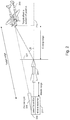
- FIG. 2 shows a missile 201 being launched towards a target 203 which is viewed in the optical sight 205.
- the target 203 is an aircraft.
- the missile 201 may be used to carry an explosive device for detonation at the target 203.
- the missile flies along the centre of the Laser Information Field 207, projected from the laser transmitter 209.
- the laser transmitter and optical sight both form part of the same device that is used to launch the missile 201; that is, the laser transmitter and optical sight are co-located with the missile launcher 211.
- the laser information field 207 encodes spatial information that can be used by the missile to determine its position within the laser beam (it will be understood that, although the laser information field is shown at a single position along the beam length in Figure 2 , in practice, the laser information field will be present along the entire length of the beam).
- the laser information field 207 is generated by operating the laser transmitter 209 in a pulsed mode and scanning the beam in the horizontal and vertical directions, perpendicular to its direction of propagation. As the beam is scanned, the intervals between successive laser pulses are varied, such that the intervals detected by the missile vary across the height and width of the Information field.
- the axes of the optical sight 205 and the laser transmitter 209 may have an offset due to mechanical tolerancing and thermal effects.
- the missile 201 is misaligned with the target.
- the target 203 is displaced by an angle ⁇ from the missile velocity vector 213.
- the term "missile velocity vector” refers to the axis of the direction of travel of the missile 201.
- the missile 201 will perform calculations based on a number of parameters, including the "target range”, “missile range” and “closing range”.
- the target range defines the true distance along the line of sight of the target 203 from the optical sight 205, whilst the missile range defines the distance of the missile 201 along the line of sight from the laser transmitter 209.
- the target range may be measured on one of several ways known in the art.
- the target range may be determined using a (separate) laser range finder provided in the same unit as the missile launcher / optical sight; alternatively, the target range may be determined by use of a radar based system, again associated with the same unit as the missile launcher / optical sight.
- Other conventional means for determining the distance from the optical sight to the target may also be employed.
- the target range may be communicated to the missile using the laser transmitter 209; that is, in addition to the spatial information encoded in the inter-pulse separation, the laser beam emitted from the laser transmitter 209 may also be used to transmit data to the missile 201 indicating the target range.
- the optical sight 205 and laser transmitter 209 are co-located with one another and the missile launcher 211; this means that the target range and missile range are both measured from the same point of origin (in practice, the nature of these devices means that the optical sight and the output of the laser transmitter may be offset from one another slightly; however, since the target range will typically be of the order of one or more kilometres, the assumption that the missile range and target range originate from the same point is valid for the purpose of correcting the missile's trajectory).
- the closing range defines the distance of the target 203 from the missile 201, as measured along the current direction of travel of the missile 201. It will be understood that Figure 2 is provided by way of illustration only and in practice, the misalignment between the target 203 and the missile 201 (i.e. the angle ⁇ ) will be much smaller than that shown - typically of the order of 1 mRad or below. As a result, the closing range can be determined to sufficient accuracy by simply subtracting the missile range from the target range.
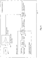
- FIG. 3 shows the components of the missile 201 in more detail.
- the missile includes one or more laser optical power receivers 303, for detecting light in the laser information field.
- the optical power receivers are, for example, aft mounted, so as to face towards the laser transmitter 209. By detecting the pulse-to-pulse intervals, the laser optical power receiver(s) 303 are able to determine the position of the missile with respect to the centre of the laser information field 207.
- the laser optical power receiver(s) may decode information that is contained in the laser beam and which specifies the current target range.
- a sensor 305 which is used to sense the position of the target relative to the missile.
- the sensor may, for example, comprise a visual sensor, an infra-red sensor or a radar sensor.
- the sensor 305 is used to determine the angular displacement ⁇ between the missile axis and the target.
- the sensor may determine the target's portion in the laser information field by detecting a portion of the field reflected by the target in both the vertical and horizontal directions.
- the sensor will have a defined field of view (FOV) and the angular offset ⁇ can be computed based on the location of the target in that field of view.
- FOV field of view
- the missile 201 also includes an Inertial Navigation System (INS) 307, used to determine the missile's position in space relative to its point of origin (i.e. the missile launcher, and correspondingly, the laser transmitter).
- the INS 307 may, for example, comprise one or more accelerometers and / or gyrometers for detecting changes in acceleration which can in turn be used to monitor the change in its position with respect to the origin over time.
- the INS 307 is used to determine the missile range and may also determine the missile's velocity vector.
- the missile range and missile velocity vector are input to a guidance processor unit 309.
- the target range and angular displacement as determined by the optical power receiver(s) 303 and the sensor 305, respectively, are also input to the guidance processor unit 309.
- the guidance processor unit 309 is used to calibrate for the misalignment between the centre of the laser information field and the aimpoint on the target from the optical sight.
- the guidance processor unit 309 sends commands to the fin control 311 to control the position of the missile by suitable adjustment of the missile fins 313.
- the guidance processor unit includes a clock or timer 401 and a look-up table that describes the width of the beam (more specifically, the area of the laser information field) as well as the expected inter-pulse separation at the missile location across the laser information field, as a function of time.
- the look-up table is depicted graphically as a plot 403 of the laser information field pattern dimension as a function of time. Based on the clock signal 401, and the look up table 403, the guidance processor unit is able to determine the expected beam resolution i.e. the grid spacing in the laser information field at a particular point in time.
- the guidance processor unit also includes a range calculator 405.
- the range calculator 405 receives as input the target range and missile range. By subtracting the missile range from the target range, the range calculator is able to determine the closing range (i.e. the distance currently remaining between the missile and the target, as measured along the missile axis).
- the closing range, as determined by the range calculator 405 is input to an offset calculator 407, together with data indicating the missile's current position in the laser information field, and the angular displacement ⁇ between the target and the missile axis.
- the data indicating the missile's current position in the laser information field includes the inter-pulse separation currently being detected by the laser optical power receiver; as described above, each point in the laser information field array has an associated inter-pulse separation, which can be used to distinguish that point from others in the array.
- the offset calculator 407 uses the inputs it receives to determine the target offset in terms of inter-pulse intervals from the missile's current position in the laser information field.
- the target offset refers to the lateral / vertical distance within the laser information field that the missile must travel in order to remain on course to hit the target.
- the target offset as measured in inter-pulse intervals may then be used to compute the distance between the centre of the laser information field and the location in the laser information field with which the missile should seek to align itself.
- the target offset is in turn input to the beam offset calculator 409.
- the beam offset calculator is able to determine the coordinates in the laser information field with which the missile should seek to align itself in order to remain on course to hit the target. More specifically, the beam offset calculator 409 determines the inter-pulse separation that when detected by the missile will confirm it as being correctly aligned with the target.
- the guidance processor issues instructions to the missile's on-board guidance systems to align the missile with the new position in the laser information field.
- the guidance processor unit may cause the missile to adjust its fins in such a way as to cause a lateral shift in the missile's position in space. In this way, the missile calibrates for any misalignment between the centre of the laser information field and the target.
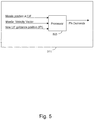
- Figure 5 shows an example of the fin control 311 used to adjust the missile's position in space.
- the fin control includes a processor 503 that receives as input the missile's current position in the laser information field (and where appropriate the missile velocity vector) together with the new inter-pulse interval (IPI) as determined by the beam offset calculator 409 in the guidance processor unit.
- the processor 503 in turn generates appropriate commands that are sent to the missile fins, so as to control the motion of the missile within the laser information field.
- Figure 6 shows a flow chart summarising the steps performed by the missile components according to an embodiment. Beginning in steps S601 and S602, the target range and missile range are determined. In step S603, the sensor on board the missile determines the angular position of the target relative to the missile axis. Then, in step S604, the closing range is calculated. In step S605, the measurements are used to determine the spatial offset between the missile's current position with respect to the laser information field and the position that the missile should adopt in order to remain on course to hit the target. In step S606, the missile's guidance systems are used to move the missile to the new position. Steps S601 to S606 then continue to repeat until target and missile lines of sight are converged.
- the missile remains under the control of the operator throughout the engagement i.e. the missile can still be self-destructed by removal of the laser information field.
- LOS Line of Sight
Landscapes
- Engineering & Computer Science (AREA)
- Chemical & Material Sciences (AREA)
- Combustion & Propulsion (AREA)
- General Engineering & Computer Science (AREA)
- Physics & Mathematics (AREA)
- Electromagnetism (AREA)
- Aiming, Guidance, Guns With A Light Source, Armor, Camouflage, And Targets (AREA)
Priority Applications (1)
| Application Number | Priority Date | Filing Date | Title |
|---|---|---|---|
| PL17154263T PL3205973T3 (pl) | 2016-02-15 | 2017-02-01 | Pocisk do wykorzystania w systemie naprowadzania pocisków w prowadzącej wiązce laserowej |
Applications Claiming Priority (1)
| Application Number | Priority Date | Filing Date | Title |
|---|---|---|---|
| GB1602648.6A GB2547278B (en) | 2016-02-15 | 2016-02-15 | Method for aligning a missile with a target in a laser beam riding missile guiding system |
Publications (2)
| Publication Number | Publication Date |
|---|---|
| EP3205973A1 true EP3205973A1 (de) | 2017-08-16 |
| EP3205973B1 EP3205973B1 (de) | 2021-09-08 |
Family
ID=55697703
Family Applications (1)
| Application Number | Title | Priority Date | Filing Date |
|---|---|---|---|
| EP17154263.2A Active EP3205973B1 (de) | 2016-02-15 | 2017-02-01 | Flugkörper zur verwendung in einem führungssystem eines laserstrahlgelenkten flugkörpers |
Country Status (4)
| Country | Link |
|---|---|
| US (1) | US10274288B2 (de) |
| EP (1) | EP3205973B1 (de) |
| GB (1) | GB2547278B (de) |
| PL (1) | PL3205973T3 (de) |
Families Citing this family (2)
| Publication number | Priority date | Publication date | Assignee | Title |
|---|---|---|---|---|
| CN111474948B (zh) * | 2019-12-25 | 2023-06-02 | 中国人民解放军海军潜艇学院 | 一种带时间控制的前置导引与姿态控制制导的方法 |
| US12540794B2 (en) * | 2024-02-21 | 2026-02-03 | Bae Systems Information And Electronic Systems Integration Inc. | Automated vision-based orientation measurement system and method of use |
Citations (5)
| Publication number | Priority date | Publication date | Assignee | Title |
|---|---|---|---|---|
| US3363858A (en) * | 1958-09-23 | 1968-01-16 | Navy Usa | Doppler homing system |
| DE2918858A1 (de) * | 1979-05-10 | 1980-11-13 | Messerschmitt Boelkow Blohm | Verfahren zur einweisung eines flugkoerper-zielsuchkopfes |
| DE4416211A1 (de) * | 1994-05-07 | 1995-11-09 | Rheinmetall Ind Gmbh | Verfahren und Vorrichtung zur Flugbahnkorrektur von Geschossen |
| GB2338284A (en) * | 1985-12-19 | 1999-12-15 | Short Brothers Plc | A missile system and method of missile guidance |
| US20140138473A1 (en) * | 2012-07-18 | 2014-05-22 | Thales Holdings Uk Plc | Missile guidance |
Family Cites Families (13)
| Publication number | Priority date | Publication date | Assignee | Title |
|---|---|---|---|---|
| US4085910A (en) * | 1972-04-12 | 1978-04-25 | Northrop Corporation | Dual mode optical seeker for guided missile control |
| US4111385A (en) * | 1976-04-16 | 1978-09-05 | Texas Instruments Incorporated | Laser beam rider guidance system |
| DE2947492C2 (de) * | 1979-11-24 | 1983-04-28 | Licentia Patent-Verwaltungs-Gmbh, 6000 Frankfurt | Lenkverfahren für Flugkörper |
| US5944281A (en) * | 1998-03-09 | 1999-08-31 | The United States Of America As Represented By The Secretary Of The Army | Dual band millimeter-infrared fiber optics guidance data link |
| US6606066B1 (en) * | 2001-10-29 | 2003-08-12 | Northrop Grumman Corporation | Tri-mode seeker |
| US7150428B2 (en) * | 2004-09-03 | 2006-12-19 | Her Majesty The Queen In Right Of Canada, As Represented By The Minister Of National Defence | Beam laser atmospheric scattering trajectory guidance |
| US7175130B2 (en) * | 2004-09-03 | 2007-02-13 | Her Majesty The Queen In Right Of Canada, As Represented By The Minister Of National Defence Of Her Majesty's Canadian Government | Missile steering using laser scattering by atmosphere |
| US8451432B2 (en) * | 2005-06-09 | 2013-05-28 | Analog-Modules, Inc. | Laser spot tracking with off-axis angle detection |
| US7397019B1 (en) * | 2005-10-19 | 2008-07-08 | Alliant Techsystems, Inc. | Light sensor module, focused light sensor array, and an air vehicle so equipped |
| US8392143B2 (en) * | 2010-11-16 | 2013-03-05 | Raytheon Company | Fixed-source array test station for calibration of a semi-active laser (SAL) seeker |
| US8411362B2 (en) * | 2011-02-25 | 2013-04-02 | Raytheon Company | Optical element retaining system for sensor systems |
| US8502128B1 (en) * | 2012-09-15 | 2013-08-06 | Raytheon Company | Dual-mode electro-optic sensor and method of using target designation as a guide star for wavefront error estimation |
| RU2582308C1 (ru) * | 2015-02-17 | 2016-04-20 | Акционерное общество "Конструкторское бюро приборостроения им. академика А.Г. Шипунова" | Способ стрельбы снарядом, управляемым по лучу лазера, и оптический прицел системы наведения снаряда |
-
2016
- 2016-02-15 GB GB1602648.6A patent/GB2547278B/en active Active
-
2017
- 2017-02-01 PL PL17154263T patent/PL3205973T3/pl unknown
- 2017-02-01 EP EP17154263.2A patent/EP3205973B1/de active Active
- 2017-02-14 US US15/432,294 patent/US10274288B2/en active Active
Patent Citations (5)
| Publication number | Priority date | Publication date | Assignee | Title |
|---|---|---|---|---|
| US3363858A (en) * | 1958-09-23 | 1968-01-16 | Navy Usa | Doppler homing system |
| DE2918858A1 (de) * | 1979-05-10 | 1980-11-13 | Messerschmitt Boelkow Blohm | Verfahren zur einweisung eines flugkoerper-zielsuchkopfes |
| GB2338284A (en) * | 1985-12-19 | 1999-12-15 | Short Brothers Plc | A missile system and method of missile guidance |
| DE4416211A1 (de) * | 1994-05-07 | 1995-11-09 | Rheinmetall Ind Gmbh | Verfahren und Vorrichtung zur Flugbahnkorrektur von Geschossen |
| US20140138473A1 (en) * | 2012-07-18 | 2014-05-22 | Thales Holdings Uk Plc | Missile guidance |
Also Published As
| Publication number | Publication date |
|---|---|
| US10274288B2 (en) | 2019-04-30 |
| PL3205973T3 (pl) | 2022-01-24 |
| EP3205973B1 (de) | 2021-09-08 |
| GB2547278A (en) | 2017-08-16 |
| GB201602648D0 (en) | 2016-03-30 |
| GB2547278B (en) | 2019-12-04 |
| US20170321994A1 (en) | 2017-11-09 |
Similar Documents
| Publication | Publication Date | Title |
|---|---|---|
| US6836320B2 (en) | Method and apparatus for active boresight correction | |
| US12573308B2 (en) | Drone optical guidance system | |
| ES2773740T3 (es) | Un sistema y procedimiento para rastrear y guiar múltiples objetos | |
| US10718850B1 (en) | Fusion between AOA and TDOA | |
| US20150241562A1 (en) | Laser navigation system and method | |
| KR20140002051A (ko) | 무인 항공기를 제어하기 위한 시스템 및 방법 | |
| CN103477187A (zh) | 用于确定新点的测量系统和方法 | |
| US4288049A (en) | Remote targeting system for guided missiles | |
| US20170268852A1 (en) | Method for steering a missile towards a flying target | |
| US7999726B2 (en) | Antenna pointing bias estimation using radar imaging | |
| KR102472938B1 (ko) | 펄스 비컨 및 저비용의 관성 측정 유닛에 의한 자세 결정 | |
| KR102619438B1 (ko) | 오프-축 타겟을 검출하기 위한 유도탄 시스템 | |
| US10274288B2 (en) | Missile for use in a laser beam riding missile guidance system | |
| JP2002538410A (ja) | 高い正確度の長距離光援助慣性誘導型ミサイル | |
| US7175130B2 (en) | Missile steering using laser scattering by atmosphere | |
| RU2674401C2 (ru) | Способ стрельбы управляемым артиллерийским снарядом | |
| US12007204B2 (en) | Method for guiding a missile, missile controller and missile | |
| US8513580B1 (en) | Targeting augmentation for short-range munitions | |
| US10215534B1 (en) | Digital light processing guidance system | |
| JP2017101870A (ja) | レーザセミアクティブ誘導方法と装置 | |
| US9574851B1 (en) | Gun alignment technique | |
| HK40070135B (en) | Attitude determination by pulse beacon and low cost inertial measuring unit | |
| HK40070135A (en) | Attitude determination by pulse beacon and low cost inertial measuring unit | |
| CN121986310A (en) | Unmanned aerial vehicle self-guided by double-purpose photoelectric distance measuring device | |
| KR20250122079A (ko) | 유도 무기용 레이저 빔 라이더 유도 제어 방법 및 유도 제어 시스템 |
Legal Events
| Date | Code | Title | Description |
|---|---|---|---|
| PUAI | Public reference made under article 153(3) epc to a published international application that has entered the european phase |
Free format text: ORIGINAL CODE: 0009012 |
|
| STAA | Information on the status of an ep patent application or granted ep patent |
Free format text: STATUS: REQUEST FOR EXAMINATION WAS MADE |
|
| 17P | Request for examination filed |
Effective date: 20170201 |
|
| AK | Designated contracting states |
Kind code of ref document: A1 Designated state(s): AL AT BE BG CH CY CZ DE DK EE ES FI FR GB GR HR HU IE IS IT LI LT LU LV MC MK MT NL NO PL PT RO RS SE SI SK SM TR |
|
| AX | Request for extension of the european patent |
Extension state: BA ME |
|
| RAP1 | Party data changed (applicant data changed or rights of an application transferred) |
Owner name: THALES HOLDINGS UK PLC |
|
| STAA | Information on the status of an ep patent application or granted ep patent |
Free format text: STATUS: EXAMINATION IS IN PROGRESS |
|
| 17Q | First examination report despatched |
Effective date: 20190523 |
|
| RIC1 | Information provided on ipc code assigned before grant |
Ipc: F41G 7/26 20060101AFI20210217BHEP Ipc: F41G 7/00 20060101ALI20210217BHEP Ipc: F41G 7/22 20060101ALI20210217BHEP Ipc: F41G 7/36 20060101ALN20210217BHEP |
|
| GRAP | Despatch of communication of intention to grant a patent |
Free format text: ORIGINAL CODE: EPIDOSNIGR1 |
|
| STAA | Information on the status of an ep patent application or granted ep patent |
Free format text: STATUS: GRANT OF PATENT IS INTENDED |
|
| RIC1 | Information provided on ipc code assigned before grant |
Ipc: F41G 7/36 20060101ALN20210309BHEP Ipc: F41G 7/00 20060101ALI20210309BHEP Ipc: F41G 7/22 20060101ALI20210309BHEP Ipc: F41G 7/26 20060101AFI20210309BHEP |
|
| INTG | Intention to grant announced |
Effective date: 20210412 |
|
| GRAS | Grant fee paid |
Free format text: ORIGINAL CODE: EPIDOSNIGR3 |
|
| GRAA | (expected) grant |
Free format text: ORIGINAL CODE: 0009210 |
|
| STAA | Information on the status of an ep patent application or granted ep patent |
Free format text: STATUS: THE PATENT HAS BEEN GRANTED |
|
| AK | Designated contracting states |
Kind code of ref document: B1 Designated state(s): AL AT BE BG CH CY CZ DE DK EE ES FI FR GB GR HR HU IE IS IT LI LT LU LV MC MK MT NL NO PL PT RO RS SE SI SK SM TR |
|
| REG | Reference to a national code |
Ref country code: GB Ref legal event code: FG4D |
|
| REG | Reference to a national code |
Ref country code: AT Ref legal event code: REF Ref document number: 1428954 Country of ref document: AT Kind code of ref document: T Effective date: 20210915 Ref country code: CH Ref legal event code: EP |
|
| REG | Reference to a national code |
Ref country code: IE Ref legal event code: FG4D |
|
| REG | Reference to a national code |
Ref country code: DE Ref legal event code: R096 Ref document number: 602017045525 Country of ref document: DE |
|
| REG | Reference to a national code |
Ref country code: LT Ref legal event code: MG9D |
|
| REG | Reference to a national code |
Ref country code: SE Ref legal event code: TRGR |
|
| REG | Reference to a national code |
Ref country code: NL Ref legal event code: FP |
|
| PG25 | Lapsed in a contracting state [announced via postgrant information from national office to epo] |
Ref country code: RS Free format text: LAPSE BECAUSE OF FAILURE TO SUBMIT A TRANSLATION OF THE DESCRIPTION OR TO PAY THE FEE WITHIN THE PRESCRIBED TIME-LIMIT Effective date: 20210908 Ref country code: LT Free format text: LAPSE BECAUSE OF FAILURE TO SUBMIT A TRANSLATION OF THE DESCRIPTION OR TO PAY THE FEE WITHIN THE PRESCRIBED TIME-LIMIT Effective date: 20210908 Ref country code: BG Free format text: LAPSE BECAUSE OF FAILURE TO SUBMIT A TRANSLATION OF THE DESCRIPTION OR TO PAY THE FEE WITHIN THE PRESCRIBED TIME-LIMIT Effective date: 20211208 Ref country code: NO Free format text: LAPSE BECAUSE OF FAILURE TO SUBMIT A TRANSLATION OF THE DESCRIPTION OR TO PAY THE FEE WITHIN THE PRESCRIBED TIME-LIMIT Effective date: 20211208 Ref country code: ES Free format text: LAPSE BECAUSE OF FAILURE TO SUBMIT A TRANSLATION OF THE DESCRIPTION OR TO PAY THE FEE WITHIN THE PRESCRIBED TIME-LIMIT Effective date: 20210908 Ref country code: FI Free format text: LAPSE BECAUSE OF FAILURE TO SUBMIT A TRANSLATION OF THE DESCRIPTION OR TO PAY THE FEE WITHIN THE PRESCRIBED TIME-LIMIT Effective date: 20210908 Ref country code: HR Free format text: LAPSE BECAUSE OF FAILURE TO SUBMIT A TRANSLATION OF THE DESCRIPTION OR TO PAY THE FEE WITHIN THE PRESCRIBED TIME-LIMIT Effective date: 20210908 |
|
| REG | Reference to a national code |
Ref country code: AT Ref legal event code: MK05 Ref document number: 1428954 Country of ref document: AT Kind code of ref document: T Effective date: 20210908 |
|
| PG25 | Lapsed in a contracting state [announced via postgrant information from national office to epo] |
Ref country code: LV Free format text: LAPSE BECAUSE OF FAILURE TO SUBMIT A TRANSLATION OF THE DESCRIPTION OR TO PAY THE FEE WITHIN THE PRESCRIBED TIME-LIMIT Effective date: 20210908 Ref country code: GR Free format text: LAPSE BECAUSE OF FAILURE TO SUBMIT A TRANSLATION OF THE DESCRIPTION OR TO PAY THE FEE WITHIN THE PRESCRIBED TIME-LIMIT Effective date: 20211209 |
|
| PG25 | Lapsed in a contracting state [announced via postgrant information from national office to epo] |
Ref country code: AT Free format text: LAPSE BECAUSE OF FAILURE TO SUBMIT A TRANSLATION OF THE DESCRIPTION OR TO PAY THE FEE WITHIN THE PRESCRIBED TIME-LIMIT Effective date: 20210908 |
|
| PG25 | Lapsed in a contracting state [announced via postgrant information from national office to epo] |
Ref country code: IS Free format text: LAPSE BECAUSE OF FAILURE TO SUBMIT A TRANSLATION OF THE DESCRIPTION OR TO PAY THE FEE WITHIN THE PRESCRIBED TIME-LIMIT Effective date: 20220108 Ref country code: SM Free format text: LAPSE BECAUSE OF FAILURE TO SUBMIT A TRANSLATION OF THE DESCRIPTION OR TO PAY THE FEE WITHIN THE PRESCRIBED TIME-LIMIT Effective date: 20210908 Ref country code: SK Free format text: LAPSE BECAUSE OF FAILURE TO SUBMIT A TRANSLATION OF THE DESCRIPTION OR TO PAY THE FEE WITHIN THE PRESCRIBED TIME-LIMIT Effective date: 20210908 Ref country code: RO Free format text: LAPSE BECAUSE OF FAILURE TO SUBMIT A TRANSLATION OF THE DESCRIPTION OR TO PAY THE FEE WITHIN THE PRESCRIBED TIME-LIMIT Effective date: 20210908 Ref country code: PT Free format text: LAPSE BECAUSE OF FAILURE TO SUBMIT A TRANSLATION OF THE DESCRIPTION OR TO PAY THE FEE WITHIN THE PRESCRIBED TIME-LIMIT Effective date: 20220110 Ref country code: EE Free format text: LAPSE BECAUSE OF FAILURE TO SUBMIT A TRANSLATION OF THE DESCRIPTION OR TO PAY THE FEE WITHIN THE PRESCRIBED TIME-LIMIT Effective date: 20210908 Ref country code: CZ Free format text: LAPSE BECAUSE OF FAILURE TO SUBMIT A TRANSLATION OF THE DESCRIPTION OR TO PAY THE FEE WITHIN THE PRESCRIBED TIME-LIMIT Effective date: 20210908 Ref country code: AL Free format text: LAPSE BECAUSE OF FAILURE TO SUBMIT A TRANSLATION OF THE DESCRIPTION OR TO PAY THE FEE WITHIN THE PRESCRIBED TIME-LIMIT Effective date: 20210908 |
|
| REG | Reference to a national code |
Ref country code: DE Ref legal event code: R097 Ref document number: 602017045525 Country of ref document: DE |
|
| PLBE | No opposition filed within time limit |
Free format text: ORIGINAL CODE: 0009261 |
|
| STAA | Information on the status of an ep patent application or granted ep patent |
Free format text: STATUS: NO OPPOSITION FILED WITHIN TIME LIMIT |
|
| PG25 | Lapsed in a contracting state [announced via postgrant information from national office to epo] |
Ref country code: DK Free format text: LAPSE BECAUSE OF FAILURE TO SUBMIT A TRANSLATION OF THE DESCRIPTION OR TO PAY THE FEE WITHIN THE PRESCRIBED TIME-LIMIT Effective date: 20210908 |
|
| 26N | No opposition filed |
Effective date: 20220609 |
|
| PG25 | Lapsed in a contracting state [announced via postgrant information from national office to epo] |
Ref country code: SI Free format text: LAPSE BECAUSE OF FAILURE TO SUBMIT A TRANSLATION OF THE DESCRIPTION OR TO PAY THE FEE WITHIN THE PRESCRIBED TIME-LIMIT Effective date: 20210908 |
|
| PG25 | Lapsed in a contracting state [announced via postgrant information from national office to epo] |
Ref country code: MC Free format text: LAPSE BECAUSE OF FAILURE TO SUBMIT A TRANSLATION OF THE DESCRIPTION OR TO PAY THE FEE WITHIN THE PRESCRIBED TIME-LIMIT Effective date: 20210908 |
|
| REG | Reference to a national code |
Ref country code: CH Ref legal event code: PL |
|
| REG | Reference to a national code |
Ref country code: BE Ref legal event code: MM Effective date: 20220228 |
|
| PG25 | Lapsed in a contracting state [announced via postgrant information from national office to epo] |
Ref country code: LU Free format text: LAPSE BECAUSE OF NON-PAYMENT OF DUE FEES Effective date: 20220201 |
|
| PG25 | Lapsed in a contracting state [announced via postgrant information from national office to epo] |
Ref country code: LI Free format text: LAPSE BECAUSE OF NON-PAYMENT OF DUE FEES Effective date: 20220228 Ref country code: IT Free format text: LAPSE BECAUSE OF FAILURE TO SUBMIT A TRANSLATION OF THE DESCRIPTION OR TO PAY THE FEE WITHIN THE PRESCRIBED TIME-LIMIT Effective date: 20210908 Ref country code: IE Free format text: LAPSE BECAUSE OF NON-PAYMENT OF DUE FEES Effective date: 20220201 Ref country code: CH Free format text: LAPSE BECAUSE OF NON-PAYMENT OF DUE FEES Effective date: 20220228 |
|
| PG25 | Lapsed in a contracting state [announced via postgrant information from national office to epo] |
Ref country code: BE Free format text: LAPSE BECAUSE OF NON-PAYMENT OF DUE FEES Effective date: 20220228 |
|
| P01 | Opt-out of the competence of the unified patent court (upc) registered |
Effective date: 20230512 |
|
| PG25 | Lapsed in a contracting state [announced via postgrant information from national office to epo] |
Ref country code: HU Free format text: LAPSE BECAUSE OF FAILURE TO SUBMIT A TRANSLATION OF THE DESCRIPTION OR TO PAY THE FEE WITHIN THE PRESCRIBED TIME-LIMIT; INVALID AB INITIO Effective date: 20170201 |
|
| PG25 | Lapsed in a contracting state [announced via postgrant information from national office to epo] |
Ref country code: MK Free format text: LAPSE BECAUSE OF FAILURE TO SUBMIT A TRANSLATION OF THE DESCRIPTION OR TO PAY THE FEE WITHIN THE PRESCRIBED TIME-LIMIT Effective date: 20210908 Ref country code: CY Free format text: LAPSE BECAUSE OF FAILURE TO SUBMIT A TRANSLATION OF THE DESCRIPTION OR TO PAY THE FEE WITHIN THE PRESCRIBED TIME-LIMIT Effective date: 20210908 |
|
| PG25 | Lapsed in a contracting state [announced via postgrant information from national office to epo] |
Ref country code: MT Free format text: LAPSE BECAUSE OF FAILURE TO SUBMIT A TRANSLATION OF THE DESCRIPTION OR TO PAY THE FEE WITHIN THE PRESCRIBED TIME-LIMIT Effective date: 20210908 |
|
| PG25 | Lapsed in a contracting state [announced via postgrant information from national office to epo] |
Ref country code: TR Free format text: LAPSE BECAUSE OF FAILURE TO SUBMIT A TRANSLATION OF THE DESCRIPTION OR TO PAY THE FEE WITHIN THE PRESCRIBED TIME-LIMIT Effective date: 20210908 |
|
| PGFP | Annual fee paid to national office [announced via postgrant information from national office to epo] |
Ref country code: GB Payment date: 20251218 Year of fee payment: 10 |
|
| PGFP | Annual fee paid to national office [announced via postgrant information from national office to epo] |
Ref country code: FR Payment date: 20251222 Year of fee payment: 10 Ref country code: NL Payment date: 20251225 Year of fee payment: 10 |
|
| PGFP | Annual fee paid to national office [announced via postgrant information from national office to epo] |
Ref country code: SE Payment date: 20251230 Year of fee payment: 10 |
|
| PGFP | Annual fee paid to national office [announced via postgrant information from national office to epo] |
Ref country code: DE Payment date: 20251224 Year of fee payment: 10 |
|
| PGFP | Annual fee paid to national office [announced via postgrant information from national office to epo] |
Ref country code: PL Payment date: 20260102 Year of fee payment: 10 |