EP3205986B1 - Système d'imagerie pour analyse de réservoir de carburant - Google Patents
Système d'imagerie pour analyse de réservoir de carburant Download PDFInfo
- Publication number
- EP3205986B1 EP3205986B1 EP17154843.1A EP17154843A EP3205986B1 EP 3205986 B1 EP3205986 B1 EP 3205986B1 EP 17154843 A EP17154843 A EP 17154843A EP 3205986 B1 EP3205986 B1 EP 3205986B1
- Authority
- EP
- European Patent Office
- Prior art keywords
- fuel tank
- fuel
- interior
- image data
- active image
- Prior art date
- Legal status (The legal status is an assumption and is not a legal conclusion. Google has not performed a legal analysis and makes no representation as to the accuracy of the status listed.)
- Active
Links
Images


Classifications
-
- G—PHYSICS
- G06—COMPUTING OR CALCULATING; COUNTING
- G06T—IMAGE DATA PROCESSING OR GENERATION, IN GENERAL
- G06T7/00—Image analysis
- G06T7/60—Analysis of geometric attributes
-
- B—PERFORMING OPERATIONS; TRANSPORTING
- B64—AIRCRAFT; AVIATION; COSMONAUTICS
- B64C—AEROPLANES; HELICOPTERS
- B64C3/00—Wings
- B64C3/34—Tanks constructed integrally with wings, e.g. for fuel or water
-
- B—PERFORMING OPERATIONS; TRANSPORTING
- B64—AIRCRAFT; AVIATION; COSMONAUTICS
- B64D—EQUIPMENT FOR FITTING IN OR TO AIRCRAFT; FLIGHT SUITS; PARACHUTES; ARRANGEMENT OR MOUNTING OF POWER PLANTS OR PROPULSION TRANSMISSIONS IN AIRCRAFT
- B64D37/00—Arrangements in connection with fuel supply for power plant
-
- G—PHYSICS
- G01—MEASURING; TESTING
- G01F—MEASURING VOLUME, VOLUME FLOW, MASS FLOW OR LIQUID LEVEL; METERING BY VOLUME
- G01F22/00—Methods or apparatus for measuring volume of fluids or fluent solid material, not otherwise provided for
-
- G—PHYSICS
- G01—MEASURING; TESTING
- G01F—MEASURING VOLUME, VOLUME FLOW, MASS FLOW OR LIQUID LEVEL; METERING BY VOLUME
- G01F23/00—Indicating or measuring liquid level or level of fluent solid material, e.g. indicating in terms of volume or indicating by means of an alarm
- G01F23/22—Indicating or measuring liquid level or level of fluent solid material, e.g. indicating in terms of volume or indicating by means of an alarm by measuring physical variables, other than linear dimensions, pressure or weight, dependent on the level to be measured, e.g. by difference of heat transfer of steam or water
- G01F23/28—Indicating or measuring liquid level or level of fluent solid material, e.g. indicating in terms of volume or indicating by means of an alarm by measuring physical variables, other than linear dimensions, pressure or weight, dependent on the level to be measured, e.g. by difference of heat transfer of steam or water by measuring the variations of parameters of electromagnetic or acoustic waves applied directly to the liquid or fluent solid material
- G01F23/284—Electromagnetic waves
- G01F23/292—Light, e.g. infrared or ultraviolet
- G01F23/2921—Light, e.g. infrared or ultraviolet for discrete levels
- G01F23/2928—Light, e.g. infrared or ultraviolet for discrete levels using light reflected on the material surface
-
- G—PHYSICS
- G01—MEASURING; TESTING
- G01F—MEASURING VOLUME, VOLUME FLOW, MASS FLOW OR LIQUID LEVEL; METERING BY VOLUME
- G01F23/00—Indicating or measuring liquid level or level of fluent solid material, e.g. indicating in terms of volume or indicating by means of an alarm
- G01F23/80—Arrangements for signal processing
- G01F23/802—Particular electronic circuits for digital processing equipment
- G01F23/804—Particular electronic circuits for digital processing equipment containing circuits handling parameters other than liquid level
-
- G—PHYSICS
- G06—COMPUTING OR CALCULATING; COUNTING
- G06T—IMAGE DATA PROCESSING OR GENERATION, IN GENERAL
- G06T7/00—Image analysis
- G06T7/60—Analysis of geometric attributes
- G06T7/62—Analysis of geometric attributes of area, perimeter, diameter or volume
-
- B—PERFORMING OPERATIONS; TRANSPORTING
- B64—AIRCRAFT; AVIATION; COSMONAUTICS
- B64D—EQUIPMENT FOR FITTING IN OR TO AIRCRAFT; FLIGHT SUITS; PARACHUTES; ARRANGEMENT OR MOUNTING OF POWER PLANTS OR PROPULSION TRANSMISSIONS IN AIRCRAFT
- B64D2203/00—Aircraft or airfield lights using LEDs
-
- G—PHYSICS
- G06—COMPUTING OR CALCULATING; COUNTING
- G06T—IMAGE DATA PROCESSING OR GENERATION, IN GENERAL
- G06T2207/00—Indexing scheme for image analysis or image enhancement
- G06T2207/10—Image acquisition modality
- G06T2207/10004—Still image; Photographic image
-
- G—PHYSICS
- G06—COMPUTING OR CALCULATING; COUNTING
- G06T—IMAGE DATA PROCESSING OR GENERATION, IN GENERAL
- G06T2207/00—Indexing scheme for image analysis or image enhancement
- G06T2207/10—Image acquisition modality
- G06T2207/10028—Range image; Depth image; 3D point clouds
-
- Y—GENERAL TAGGING OF NEW TECHNOLOGICAL DEVELOPMENTS; GENERAL TAGGING OF CROSS-SECTIONAL TECHNOLOGIES SPANNING OVER SEVERAL SECTIONS OF THE IPC; TECHNICAL SUBJECTS COVERED BY FORMER USPC CROSS-REFERENCE ART COLLECTIONS [XRACs] AND DIGESTS
- Y02—TECHNOLOGIES OR APPLICATIONS FOR MITIGATION OR ADAPTATION AGAINST CLIMATE CHANGE
- Y02T—CLIMATE CHANGE MITIGATION TECHNOLOGIES RELATED TO TRANSPORTATION
- Y02T50/00—Aeronautics or air transport
- Y02T50/40—Weight reduction
Definitions
- the present invention relates to fluid storage systems, and in particular to determining properties of fuel tanks and their contents.
- fuel tanks such as the volume and/or mass of fuel remaining.
- These tanks may exist in complex environments, such as the wing of the aircraft, for example.
- Various factors may affect the orientation of fuel within these tanks, such as tilt of the aircraft and bending of the wing. It is desirable to know how each of these factors are presently affecting a tank, so as to facilitate accurate determination of remaining fuel.
- the invention relates to a method and a system as described in claims 1 and 8.
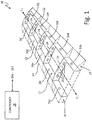
- FIG. 1 is a diagram illustrating fuel tank monitoring system 10, which includes fuel tank 12 disposed within aircraft wing 14.
- Fuel tank monitoring system 10 includes imagers 16a-16j for determining fluid and/or physical properties of fuel tank 12.
- Wing 14 is oriented about centerline C L and includes trailing edge space 18, leading edge space 20, and fuel tank 12.
- fuel tank 12 is defined by spars 22, and upper and lower skins of wing 14.
- Wing 14 includes structural members such as spars 22 and ribs 24, which may be internal or external to fuel tank 12, or may define boundaries of fuel tank 12.
- Ribs 24 may include structural elements 26, which are illustrated as holes within ribs 24.
- Fuel tank 12 may include many more structural elements (i.e., physical features) not shown in FIG. 1 , which may be in addition to, or part of, spars 22 and ribs 24. While illustrated within wing 14, fuel tank 12 may be any structure designed to hold a fluid.
- Fuel tank monitoring system 10 may also include controller 28, which may be operatively connected to provide two-way communication with imagers 16a-16n.
- Controller 28 may be a microprocessor implemented within a fuel avionics system, for example.
- each imager 16a-16j may include its own respective controller in addition to, or in replacement of, controller 28.
- Controller 28, in some examples, can include one or more processors and computer-readable memory encoded with instructions that, when executed by the one or more processors, cause controller 28 and/or other elements of fuel tank monitoring system 10 to operate in accordance with techniques described herein. Examples of such processors can include any one or more of a microprocessor, a controller, a digital signal processor (DSP), an application specific integrated circuit (ASIC), a field-programmable gate array (FPGA), or other equivalent discrete or integrated logic circuitry.
- DSP digital signal processor
- ASIC application specific integrated circuit
- FPGA field-programmable gate array
- Computer-readable memory of controller 28 can be configured to store information within controller 28 during operation.
- Computer-readable memory in some examples, can be described as a computer-readable storage medium.
- a computer-readable storage medium can include a non-transitory medium. The term "non-transitory" can indicate that the storage medium is not embodied in a carrier wave or a propagated signal.
- a non-transitory storage medium can store data that can, over time, change (e.g., in RAM or cache).
- computer-readable memory of controller 28 can include temporary memory, meaning that a primary purpose of the computer-readable memory is not long-term storage.
- Computer-readable memory of controller 28 in some examples, can be described as a volatile memory, meaning that the computer-readable memory does not maintain stored contents when electrical power to controller 28 is removed. Examples of volatile memories can include random access memories (RAM), dynamic random access memories (DRAM), static random access memories (SRAM), and other forms of volatile memories.
- RAM random access memories
- DRAM dynamic random access memories
- SRAM static random access memories
- computer-readable memory can be used to store program instructions for execution by one or more processors of controller 28.
- computer-readable memory of controller 28 can be used by software or applications executed by controller 28 to temporarily store information during program execution.
- Imagers 16a-16j may be any image capture devices capable of producing an analog or digital image from received light at one or more wavelengths.
- Imagers 16a-16j may be, for example, cameras, short-wave infrared imagers, thermal imagers, fiber optic bundles, or any other device capable of capturing light to form an image. While illustrated as located on external surfaces of fuel tank 12, imagers 16a-16j may be implemented anywhere internal or external to fuel tank 12. Imagers 16a-16j may be located in positions so as to obtain a complete two-dimensional and/or three-dimensional representation of fuel tank 12, or may be implemented to only obtain images of desired locations of fuel tank 12. For example, fewer imagers 16a-16j may be implemented in fuel tank 12, and the portions of tank 12 that are not captured in any field of view of imagers 16a-16j may be inferred based upon the known structure of fuel tank 12.
- Imagers 16a-16j may provide image data to controller 28 to determine properties of fuel tank 12.
- Image data may be obtained using any device capable of producing electronic data based upon incoming light such as, for example, a focal-plane array.
- the properties of fuel tank 12 may include, but are not limited to, physical features of an interior of fuel tank 12 (e.g., locations and/or physical contours of spars 22, ribs 24, structural elements 26, or other physical features of the interior of fuel tank 12), a level and/or volume of fuel within the interior of fuel tank 12, tilt of an aircraft that includes fuel tank 12, an amount of bend of wing 14 of the aircraft, a density of the fuel within fuel tank 12, a chemical composition of fluids within fuel tank 12 (e.g., fuel, gases within an ullage of fuel tank 12, or other fluids within fuel tank 12), and/or a temperature of fluid(s) within fuel tank 12.
- fluids within fuel tank 12 e.g., fuel, gases within an ullage of fuel tank 12, or other fluids within fuel tank 12
- processing may be performed on the image data obtained by imagers 16a-16j.
- the focal-plane array or other image sensing device of imagers 16a-16j may be configured to output an array of pixels, for example.
- the array of pixels may be provided to a local controller of imager 16a-16j, or controller 28, for processing.
- Controller 28 can utilize the determined properties of fuel tank 12 to produce a fuel measurement value representing an amount of fuel contained in fuel tank 12.
- the fuel measurement value can include, for example, a volume of fuel, a mass of fuel (e.g., based on a volume and density of the fuel), or other fuel measurement values representing an amount of fuel contained in fuel tank 12.
- Controller 28 can output an indication of the fuel measurement value, such as by outputting data specifying the fuel measurement value via a communications data bus or other network (not illustrated), a visual indicator (e.g., a graphical gauge, a warning light, or other visual indicator) of the fuel measurement value, or other indication of the fuel measurement value.
- a visual indicator e.g., a graphical gauge, a warning light, or other visual indicator
- imagers 16a-16j By utilizing imagers 16a-16j to determine properties of fuel tank 12, prior art capacitive probes may be eliminated (or a number of capacitive probes reduced) from fuel tank 12, which removes or reduces the electromagnetic fields generated by the capacitive probes.
- imagers 16a-16j are implemented external to fuel tank 12, obtaining a field of view through, for example, a window, all electronic components used for fuel volume determinations may be removed from fuel tank 12. Further, many or all of the electronics for imagers 16a-16j may be contained within leading edge space 20 and trailing edge space 18, regardless of the imagers' locations inside or outside of fuel tank 12. This can reduce the need for opening fuel tank 12 to provide service for imagers 16a-16j.
- Imagers 16a-16j may also be utilized to perform inspections of the internals of fuel tank 12, further reducing the need for entry into fuel tank 12.
- image data obtained by imagers 16a-16j may be utilized to perform routine inspections for corrosion, cracks or other maintenance needs within fuel tank 12.
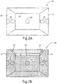
- FIGS. 2A and 2B are example images 30a and 30b captured by imager 16a. While illustrated as images 30a and 30b captured by imager 16a, images 30a and 30b may be captured by any imager 16a-16j implemented for fuel tank 12. Moreover, it should be understood that in some examples, techniques described herein can utilize more than the two images 30a and 30b described with respect to the example of FIGS. 2A and 2B.
- FIG. 2A illustrates reference image 30a which may be a reference for the field of view of imager 16a. Reference image 30a may be taken at any reference time for fuel tank 12. For example, and as illustrated in FIG. 2A , reference image 30a may be obtained by imager 16a during a time in which fuel tank 12 does not contain any fuel.
- reference image 30a can be obtained by imager 16a during a time when fuel tank 12 contains fuel. Reference image 30a may also be obtained while the aircraft is on the ground when fuel tank 12 is at or near empty to help ensure that there is minimal wing bending, which may affect the orientation of physical features within fuel tank 12. While illustrated as a reference image obtained while on the ground with minimal fuel in fuel tank 12, reference image 30a may be obtained at any other time, such as when the aircraft is in air and/or when fuel tank 12 contains fuel.
- FIG. 2B illustrates active image 30b which may be actively obtained during operation of fuel tank monitoring system 10 and/or the aircraft for which fuel tank monitoring system 10 is implemented.
- Active image 30b depicts an instance in which fuel is present within fuel tank 12.
- Fuel level lines 32a-32c are illustrated to depict a level of fuel on each surface of fuel tank 12 that is in the field of view of imager 16a.
- Fuel level lines 32a-32c represent an interface between fuel and ullage (i.e., an unfilled space of fuel tank 12 that can be occupied by one or more gases).
- Active image 30b may be obtained using the same imager 16a-16j that was used to obtain reference image 30a. Therefore, images 30a and 30b may be processed by controller 28 to determine at least the level of fuel in fuel tank 12.
- Image processing may be performed by controller 28, for example, to determine the location of fuel level lines 32a- 32c.
- This image processing may include feature recognition, edge detection, or any other type of image recognition.
- Feature recognition for example, may perform an image-to-image overlay to compare active image 30b to reference image 30a in order to determine locations of the interior of fuel tank 12 where images 30a and 30b do not match.
- Controller 28 may detect disconnects from the overlay to determine where fuel level lines 32a-32c are located.
- Edge detection may also be utilized to detect fuel level lines 32a-32c. Edge detection may be performed by searching active image 30b for sharp changes in light intensity. For example, if image 30b includes an array of pixels, controller 28 may search the pixel array to detect adjacent pixels that have a significant difference in intensity. Once controller 28 detects edges within fuel tank 12, a comparison may be made to the known structure in the field of view of imager 16a to determine if the edges are indicative of the fuel interface.
- controller 28 can store a model of a shape of fuel tank 12, such as a model defined using computer aided design (CAD) technologies that includes relative locations of physical features of the shape of fuel tank 12, including physical features corresponding to external boundaries of, and internal physical features of, the interior of fuel tank 12 (e.g., spars 22, ribs 24, structural elements 26, or other physical features of the interior of fuel tank 12).
- CAD computer aided design
- any other image processing techniques such as the use of machine learning techniques (e.g., artificial neural networks, Bayesian networks, support vector machines, or other types of machine learning techniques), may be utilized to process active images 30b to determine a location and/or intersection of fuel level lines 32a-32c with physical features of the interior of fuel tank 12.
- three fuel level lines 32a-32c may be determined from the field of view of imager 16a. Active images from other imagers 16b-16j may also be utilized to determine fuel level lines for each wall of fuel tank 12, for example. If locations of fuel level lines are determined for each wall of fuel tank 12, the volume of fuel may be determined. For instance, controller 28 can compare one or more locations of the interior of fuel tank 12 corresponding to the determined fuel level lines that correspond to (e.g., intersect) locations of one or more physical features of the interior of fuel tank 12 (e.g., determined based on reference image 30a, a model of the shape of fuel tank 12, or combinations thereof).
- Controller 28 can determine, in some examples, an amount of fuel that is between the determined fuel level lines and a bottom of fuel tank 12 (i.e., a bottom of fuel tank 12 as defined with respect to level flight of the aircraft).
- the tilt of the aircraft may also be determined by knowing the fuel level lines for each wall of fuel tank 12. For example, if fuel level line 32a of image 30b is higher than fuel level line 32c, controller 28 may be able to determine a tilt of the aircraft based on fuel level lines 32a-32c and the known geometry of fuel tank 12 (e.g., known via the model of the shape of fuel tank 12).
- FIG. 3 is a diagram that illustrates fuel tank 12 including imagers 40a and 40b.
- Imagers 40a and 40b are capable of viewing top portion 42a and bottom portion 42b of fuel tank 12, respectively, to detect a fuel interface 44.
- Imagers 40a and 40b may include light sources 46a and 46b, respectively. While illustrated in FIG. 3 as located inside fuel tank 12, imagers 40a and 40b may also be located outside of fuel tank 12 while still having a view of the inside structure of fuel tank 12 through a window, for example.
- the field of view for each imager 40a and 40b is illustrated by the arrows in FIG. 3 .
- Imager 40a may be located proximate to (e.g., attached to or otherwise disposed proximate to) the top skin of wing 14, which may also be the top boundary of fuel tank 12 in some examples. Imager 40a may therefore have a field of view that is capable of imaging bottom portion 42b of fuel tank 12. Imager 40b may be located proximate to (e.g., attached to or otherwise disposed proximate to) the bottom skin of wing 14, which may also be the bottom boundary of fuel tank 12 in some examples. Imager 42a may therefore have a field of view that is capable of imaging top portion 42a of fuel tank 12.
- Light sources 46a and 46b may be implemented to illuminate the internal structure of fuel tank 12. Light sources 46a and 46b may be any devices capable of emitting light at any desired wavelength or range of wavelengths such as, for example, a laser, a light-emitting diode (LED), or any other light emitter.
- Imager 40a may be submerged below fuel interface 44, for example.
- controller 28 may not be able to detect fuel interface 44 within fuel tank 12 based on an image from imager 40a.
- imager 40b that is located with a field of view of upper portion 42a can enable controller 28 to detect fuel interface 44 based upon an image from imager 40b.
- Detection of fuel interface 44 may be accomplished using any type of image processing techniques capable of detecting fuel interface 44 from electronic data obtained by imagers 40a and 40b, such as the techniques discussed above.
- an image-to-image overlay may be used to determine a location and/or intersection of fuel level lines with physical features of the interior of tank 12 to determine a location of fuel interface 44.
- imager 40a may be implemented outside fuel tank 12 such that imager 40a is never submerged below fuel interface 44 and therefore, imager 40b is not required to determine the location of fuel interface 44.
- fuel interface 44 may be below the field of view of imager 40b.
- imager 40a located with a field of view that includes lower portion 42b, can enable controller 28 to detect fuel interface 44 even though it is below the level of imager 40b.
- all possible locations of fuel boundary 44 may be detected within fuel tank 12 utilizing imagers 40a and 40b.
- Light sources 46a and 46b may be controlled in any desirable manner to illuminate fuel tank 12 for imagers 40a and 40b. Although illustrated as integral to imagers 40a and 40b, light sources 46a and 46b may also be implemented as devices separate from imagers 40a and 40b. Because imagers 40a and 40b produce image data based upon collected light, it may be desirable to control an intensity, and direction, of light within fuel tank 12. For example, light source 46a can be turned on to provide reflective light for detecting fuel interface 44 by imager 40a and/or transmissive light for detecting fuel interface 44 by imager 40b. Light source 46b can be turned on to provide transmissive light for detecting fuel interface 44 by imager 40a and reflective light for detecting fuel interface 44 by imager 40b. In other embodiments, both light sources 46a and 46b may be turned on for detection of fuel interface 44 by one or more of imagers 40a and 40b. Similar operation of light sources 46a and 46b may be performed for any other imager implemented within fuel tank 12.
- FIG. 4A illustrates wing 14 with no bending
- FIG. 4B illustrates wing 14 with bending
- Wing 14 includes imager 50 disposed therein, and also includes structural elements 52a-52d (i.e. physical features of the interior of fuel tank 12).
- Imager 50 may be any type of image capture device, including any of those discussed in previous embodiments.
- Imager 50 may have a field of view illustrated by the arrows extending from imager 50 in FIGS. 4A and 4B . This field of view may be such that imager 50 is able to obtain image data that includes all of structural elements 52a-52d relative to one another. With no bend, wing 14 remains oriented about centerline C L .
- wing 14 With bending, the tip of wing 14 is displaced below centerline C L and is oriented about a bend line C B .
- the angle ⁇ B is the angle between centerline C L and bend line C B . While illustrated as bending downward, which may occur during refueling of an aircraft on the ground, for example, wing 14 may also bend upward during flight.
- Wing bending may be important in determining a level of fuel within fuel tank 12 because the orientation of fuel within fuel tank 12 may be altered due to bending in wing 14. In addition to determination of fuel levels, a determination of wing bending of wing 14 may be useful for other systems of an aircraft. Because imager 50 may be utilized to detect wing bending in addition to detecting fuel levels as described in the previous embodiments, no extra systems need to be implemented on the aircraft to detect wing bending.
- FIG. 5A illustrates an example reference image 53a obtained by imager 50 while wing 14 has no bend (e.g., for the embodiment illustrated in FIG. 4A), and FIG. 5B illustrates an active image 53b obtained by imager 50 while wing 14 has a bend of ⁇ B (e.g., for the embodiment illustrated in FIG. 4B ). While illustrated as holes within structural elements 52a-52d, any other structural members may be compared to one another to determine an amount of wing bending ⁇ B . While illustrated as ribs of wing 14, structural elements 52a-52d may be any structural elements within wing 14 that may be viewed relative to one another.
- imager 50 can be located to have a field of view of any portion of the interior of fuel tank 12, such that controller 28 can determine an amount of wing bending of wing 14 based on relative displacement of physical features of the interior of fuel tank 12 based on the generated image data from the one or more imagers, as is further described below.
- Images 53a and 53b include distances 54a-54c.
- Distance 54a is the distance between the bottom edge of the hole in structural element 52a and the bottom edge of the hole in structural element 52b.
- Distance 54b is the distance between the bottom edge of the hole in structural element 52b and the bottom edge of the hole in structural element 52c.
- Distance 54c is the distance between the bottom edge of the hole in structural element 52c and the bottom edge of the hole in structural element 52d. While illustrated as three distances 54a-54c, any number of comparisons between structural elements of wing 14 may be utilized to achieve a desired accuracy of the detected wing bending.
- the angle ⁇ B may be determined by comparing distances 54a-54c of image 53b, with distances 54a-54c of image 53a to determine a relative displacement between structural elements 52a-52d that can correspond to an amount of wing bending of wing 14. Controller 28, or any other controller, may accomplish this by using any form of image processing, such as those discussed above. Image 53b may be compared to image 53a using an image-to-image overlay, for example, and the difference between distances 54a-54c of images 53b and 53a may be determined.
- the base distances 54a-54c are known (e.g., via a model of a shape of fuel tank 12 that specifies relative locations of physical features of the interior of fuel tank 12), other forms of image processing may be utilized to determine distances 54a-54c of image 53b, and those distances 54a-54c may be compared to the base values to determine an amount of wing bending ⁇ B . While the embodiment discussed with reference to FIGS. 4A-5B may be utilized to detect a single angle ⁇ B , the techniques described herein may be applied to detect higher-dimensional properties of wing bending by using, for example, three-dimensional modeling of wing 14 based on images obtained from imagers positioned within wing 14.
- Controller 28 can utilize the determined amount of wing bending ⁇ B to determine a fuel measurement value representing an amount of fuel contained in fuel tank 12, such as a fuel volume, a fuel mass, or other fuel measurement values representing an amount of fuel contained in fuel tank 12. For instance, controller 28 can store and/or determine a model of a shape of fuel tank 12, such as a model defined by CAD or other techniques that specified relative locations of physical features of the interior of fuel tank 12. Controller 28 can determine the fuel measurement value based on the determined amount of wing bending ⁇ B , such as by modifying the shape of fuel tank 12 using the model of the shape of fuel tank 12 and determining the fuel measurement value based on the modified shape.
- controller 28 can modify the locations of physical features of the interior of fuel tank 12 within the model based on the determined amount of wing bending ⁇ B .
- Controller 28 can determine the fuel measurement value representing the amount of fuel contained in fuel tank 12 based on the a location of fuel and ullage (e.g., associated with one or more of fuel level lines 32a-32c, or more fuel level lines) corresponding to (e.g., intersecting) locations of one or more of the physical features of the interior of fuel tank 12 defined using the modified shape within the model.
- FIG. 6 is a diagram illustrating fuel tank 12 that includes time-of-flight imager 60.
- Time-of-flight imager 60 may be implemented as a Light Detection and Ranging (lidar) device or any other image capture device capable of measuring a time-of-flight of reflected light.
- Time-of-flight imager 60 may emit light 64 outward from time-of-flight imager 60 using a built-in, or separate, directional light source as illustrated by the arrows in FIG. 6 .
- Light 64 may be emitted utilizing a laser, or any other light source capable of emitting light at a known wavelength. Lasers provide a directed light source that can be emitted toward fuel interface 62.
- Light 64 is reflected off of fuel interface 62 and may be obtained and analyzed by controller 28, for example. As illustrated in FIG. 6 , other features, such as spars 22 and structural features 26 may also be detected by time-of-flight imager 60 based upon reflected light.
- Time-of-flight imager 60 may include a focal plane array, for example, that provides an image on a pixel-by-pixel basis. For each pixel, a time-of-flight may be determined based upon a known time of sending out light 64 by the laser or other light source of time-of-flight imager 60. Any type of time-of-flight detection may be utilized such as, for example, range gating or direct time-of-flight to provide an indication of time-of-flight for each pixel.
- the time-of-flight may be indicated based upon an intensity of the pixel, whereas for direct time-of-flight, the actual time-of-flight for the light to travel from the light source and back to the imager is measured for each pixel.
- the phase of the reflected light 64 may be used by time-of-flight imager 60 to determine, on a pixel-by-pixel basis, the time-of-flight for light 64 to travel from the light source back to imager 60.
- the phase of the light is shifted based upon the distance the light traveled prior to reflection. Therefore, the phase of light for each pixel may be utilized to determine a time-of-flight for each pixel.
- a three-dimensional image of fuel tank 12 may be determined (e.g., by controller 28). Controller 28, utilizing the generated three-dimensional image data, can determine three-dimensional properties of fuel tank 12, such as a location of physical features of the interior of fuel tank 12, a location of fuel interface 62 (i.e., representing an interface between fuel and ullage of fuel tank 12), a location of fuel interface 62 corresponding to (e.g., intersecting) the physical features of the interior of fuel tank 12, a tilt of the aircraft including fuel tank 12, a bending of wing 14 including fuel tank 12 (e.g., based on a relative displacement of the identified physical features of the interior of the fuel tank 12 as compared to a model of the shape of fuel tank 12), or other three-dimensional properties of fuel tank 12.
- controller 28 utilizing the generated three-dimensional image data, can determine three-dimensional properties of fuel tank 12, such as a location of physical features of the interior of fuel tank 12, a location of fuel interface 62 (i.e., representing an interface between fuel and ullage of
- Such three-dimensional data can enable controller 28 to determine a fuel measurement value corresponding to an amount of fuel contained in fuel tank 12 without comparison to or generation of reference images of the interior of fuel tank 12.
- fuel interface 62 is illustrated in FIG. 6 with tilt, indicating that the aircraft carrying fuel tank 12 is tilted with respect to the local acceleration vector of the aircraft.
- the tilt of fuel interface 62 may be determined with great precision.
- time-of-flight imager 60 may be implemented anywhere in which it is possible to get an internal image of fuel tank 12, such as external to fuel tank 12 through a window, for example. Time-of-flight imager 60 may also be utilized in any of the previous embodiments disclosed to detect fuel levels, wing bending, tilt, or any other properties of fuel tank 12.
- any of the imagers illustrated in FIGS. 1-6 may be configured to determine a fuel interface or other property of a fuel tank based on a pattern of light.
- imager 60 of FIG. 6 may be configured to project a pattern of light in fuel tank 12. This pattern may be, for example, several beams of light projected in different, but known, directions. All beams may be configured to hit fuel interface 62 regardless of the level of fuel in fuel tank 12. Because the beams are projected in different directions from the light source of imager 60, the pattern will change based on the location and orientation of fuel interface 62 relative to imager 60.
- Imager 60 may produce an image that illustrates the three reflected points. Using the three reflected points, as well as the known direction of the beams from imager 60, a location and orientation of fuel interface 62 may be determined.
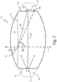
- FIG. 7 is a diagram illustrating fuel tank 12 that includes light source 70 and imager 72 utilized to determine a density of fluid (e.g., fuel) within fuel tank 12.
- Imager 72 may be any image capture device such as those discussed in the above embodiments.
- Light source 70 may be any light source, such as any of those discussed in the above embodiments. While illustrated as external to fuel tank 12 in wing space 20, imager 72 may be located at different positions external to or internal to fuel tank 12
- Refraction of the light emitted from light source 70 after the light passes through an interface with fuel contained in fuel tank 12 may be utilized to determine a density of the fuel within fuel tank 12.
- the interface with the fuel contained in fuel tank 12 can be an interface between the fuel and gas within an ullage of fuel tank 12.
- the interface with the fuel contained in fuel tank 12 can include an interface between, e.g., a window separating light source 70 and fuel contained in fuel tank 12.
- a directed beam of light 78 emitted by light source 70 may be aimed at one of spars 22, or any other structural element of fuel tank 12, for example.
- Location 76a may be the location of the interior of fuel tank 12 that beam 78 hits (i.e., intersects) after traveling through fuel interface 74.
- Location 76b may be a location of the interior of fuel tank 12 corresponding to non-refraction of beam 78, such as the location that beam 78 hits (i.e., intersects) after traveling through fuel tank 12 when fuel tank 12 is empty of fuel (illustrated by the dashed line in FIG. 7 ).
- Angle ⁇ 1 is the angle of beam 78 above fuel interface 74 relative to normal L N .
- Angle ⁇ 2 which can be considered a refraction angle of beam 78 after beam 78 passes through the interface with the fuel (fuel interface 74 in this example), is the angle of beam 78 relative to normal L N below fuel interface 74.
- Angle ⁇ 1 may be known based on the installed location and directional orientation of light source 70. If the level of fuel interface 74 is also known, the distance D 1 may be utilized to determine angle ⁇ 2 . This may be advantageous when measuring the density of fuel, for example, prior to takeoff when the level of fuel interface 74 is known.
- Imager 72 may be implemented to receive reflected light 80 to determine position 76a.
- Position 76a may be determined by controller 28, for example, using image processing techniques, such as those discussed in the above embodiments.
- Location 76b may be a known reference location indicative of non-refraction of beam 78, such as the location of the interior of fuel tank 12 that beam 78 hits when there is no fuel in tank 12. By comparing the determined location 76a obtained from the image data to the reference location 76b, distance D 1 may be calculated.
- controller 28 may process an image-to-image overlay of a first image that includes the detected location 76a, and a reference image that includes reference location 76b to determine a distance between locations 76a and 76b within the overlay.
- the determined distance within the overlay may then be correlated to the actual physical distance D 1 .
- ⁇ 2 may be determined by controller 28.
- controller 28 can utilize Snell's law to determine the refractive index of the fuel.
- known properties of the fuel within fuel tank 12, along with a sensed temperature of the fuel may be utilized to calculate the density of the fuel based on the refractive index.
- the temperature of the fuel must be known, as temperature is also a variable that affects refractive index.
- a temperature probe (not shown) may be implemented to sense the temperature of the fuel.
- imager 72 may be implemented, for example, as a far infrared imager, or any other thermal imager, to detect blackbody radiation.
- a far infrared imager may produce electronic data indicative of temperature in its field of view.
- Each pixel for example, may have an intensity that is directly proportional to the temperature of the objects within the image.
- a thermal imager is also capable of receiving the radiation of beam 80 to determine location 76a.
- a thermal imager may be implemented in any of the above embodiments to both obtain images of fuel tank 12 as well as determine the temperature of the contents of fuel tank 12.
- Controller 28 can determine a fuel measurement value representing an amount of fuel contained in fuel tank 12 based on the determined density of the fuel. For instance, controller 28 can determine a fuel measurement value representing a mass of fuel contained in fuel tank 12 based on the determined density and a determined volume of the fuel contained in fuel tank 12. Accordingly, techniques described herein can enable a density of fuel contained within fuel tank 12 using imaging techniques, thereby enabling fuel measurement values, such as a mass of fuel contained in fuel tank 12, to be determined.
- FIGS. 8A and 8B are diagrams illustrating imagers 92 and 100, respectively, implemented to determine properties of ullage gases 96.
- FIG. 8A illustrates fuel tank 12 that includes light source 90 and imager 92. Fuel interface 94 separates the fuel in tank 12 from ullage gases 96.
- Light source 90 which may be any light source such as those described in the above embodiments, may be configured to produce directional light beam 98 for receipt by imager 92.
- FIG. 8B illustrates an imager 100 that includes a local light source, which produces light beam 102 that is directed at the opposing spar 24 and reflected back for receipt by imager 100.
- imagers 92 and 100 may be utilized to determine the absorption of at least one wavelength of beams 98 and 102, respectively.
- Aircraft systems may include inert gas generating systems configured to produce oxygen-depleted air for the fuel tank ullage to reduce the probability of combustion within the fuel tank. In particular, it is desirable to ensure that oxygen levels remain below a threshold percentage of ullage gases 96. In the example of FIGS.
- fuel tank monitoring system 10 can include and/or be operatively coupled to such an inert gas generating system the produces oxygen-depleted ullage gases 96 (e.g., comprised of, e.g., nitrogen gas or other inert gas).
- oxygen-depleted ullage gases 96 e.g., comprised of, e.g., nitrogen gas or other inert gas.
- an amount of inert gas present within ullage gases 96 can be determined.
- Oxygen for example, includes a series of absorbing bands and thus, the wavelengths of light beams 98 and 102 can be selected to be within the absorbing bands of oxygen.
- inert gases such as nitrogen, include a series absorbing bands that may be different than the absorbing bands of oxygen.
- the wavelengths of light beams 98 and 102 can be selected to be within the absorbing bands of the inert gas. Absorption is distance dependent, so the distance that light beams 98 and 102 travel prior to arriving at imagers 90 and 102, respectively, must be known.
- the light received at imagers 90 and 102 may be analyzed by controller 28, for example, to determine an amount of absorption of the at least one wavelength corresponding to a selected constituent of ullage gases 96, such as oxygen, inert gas (e.g., nitrogen gas), or other selected constituent.
- a selected constituent of ullage gases 96 such as oxygen, inert gas (e.g., nitrogen gas), or other selected constituent.
- an intensity of light received by imagers 90 and 102 may be known as a reference for when no oxygen is present. This reference may be compared to the active intensity of light received by imagers 90 and 102 to determine an amount of absorption of the at least one wavelength.
- This amount of absorption along with the known distance of travel for beams 98 and 102, may be utilized to determine a level of a constituent, such as oxygen, inert gas, or other constituent within ullage gases 96.
- Such determined levels of constituent can be indicative of an operational status of the inert gas generating system. For instance, a presence of oxygen or amount of oxygen that exceeds a threshold acceptability value can indicate a leak or other malfunction of the inert gas generating system configured to generate the oxygen-depleted air.
- Controller 28 can determine the operational status of the inert gas generating system based on the determined amount of absorption of the at least one wavelength of one or more of light beams 98 and 102. For instance, controller 28 can determine an amount of a constituent, such as oxygen, nitrogen, or other constituent of ullage gases 96 based on the determined absorption. Controller 28 can determine the operational status of the inert gas generating system corresponding to a failure mode of the inert gas generating system in response to determining that the amount of the constituent present in ullage gases 96 deviates from one or more threshold acceptability criteria.
- the one or more threshold acceptability criteria can include a threshold maximum limit corresponding to a maximum acceptable amount of the constituent (e.g., oxygen). Controller 28 can determine that the amount of constituent present in ullage gases 96 deviates from the one or more threshold acceptability criteria in response to determining that the amount of constituent present in ullage gases 96 exceeds the threshold maximum limit corresponding to the maximum acceptable amount of the constituent.
- the one or more threshold acceptability criteria can include a threshold minimum limit corresponding to a minimum acceptable amount of the constituent (e.g., nitrogen gas or other inert gas).
- Controller 28 can determine that the amount of constituent present in ullage gases 96 deviates from the one or more threshold acceptability criteria in response to determining that the amount of constituent present in ullage gases 96 is less than the threshold minimum limit corresponding to the minimum acceptable amount of the constituent.
- controller 28 can determine an operational status of an inert gas generating system configured to generate oxygen-depleted air for ullage of fuel tank 12.
- the techniques described herein can increase awareness of the operational status of the inert gas generating system, thereby increasing system safety. While described with reference to imagers 92 and 100, in other embodiments, a single photo sensor may also be utilized in place of imagers 92 and 100 to detect an intensity of light from beams 98 and 102, respectively.
- FIGS. 9-13 are flow diagrams illustrating example operations for determining properties of a fuel tank utilizing one or more image capture devices. For purposes of clarity and ease of discussion, the example operations are described below within the context of fuel tank monitoring system 10 and the embodiments described above.
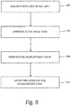
- FIG. 9 is a flow diagram illustrating example operations to produce a fuel measurement value representing an amount of fuel contained in a fuel tank based on reference image data and active image data of an interior of the fuel tank.
- Reference image data can be generated representing a field of view of an interior of a fuel tank (Step 104).
- imager 16a can generate reference image 30a representing a field of view of the interior of fuel tank 12.
- Active image data can be generated representing the field of view of the interior of the fuel tank when the fuel tank contains fuel (Step 106).
- imager 16a can generate active image 30b representing the field of view of the interior of fuel tank 12 when fuel tank 12 contains fuel.
- a fuel measurement value can be produced representing an amount of fuel contained in the fuel tank based on the reference image data and the active image data (Step 108).
- controller 28 can produce a fuel measurement value representing a volume of fuel contained in fuel tank 12 based on image processing techniques to locate fuel level lines 32a-32c and determine the volume of fuel based on a correspondence of fuel level lines 32a-32c with one or more physical features of the interior of fuel tank 12.
- An indication of the fuel measurement value can be provided as output (Step 110). For instance, controller 28 can output data including the fuel measurement value via one or more communication data buses.
- FIG. 10 is a flow diagram illustrating example operations to produce a fuel measurement value representing an amount of fuel contained in a fuel tank disposed within a wing of an aircraft based on a determined amount of wing bending of the wing.
- Image data can be generated of an interior of a fuel tank disposed within a wing of an aircraft (Step 112).
- imager 50 can generate reference image data 53a and active image data 53b of the interior of fuel tank 12 disposed within wing 14 of an aircraft.
- An amount of wing bending of the wing of the aircraft can be determined based on the generated image data of the interior of the fuel tank (Step 114).
- controller 28 can determine distances 54a-54c between structural elements 52a-52d for each of reference image data 53a and active image data 53b, and can compare the distances 52a-52d between each of reference image data 53a and active image data 53b to determine angle ⁇ B as the determined amount of wing bending of wing 14.
- a fuel measurement value representing an amount of fuel contained in the fuel tank can be produced based on the amount of wing bending of the wing of the aircraft (Step 116).
- controller 28 can modify a shape of fuel tank 12 using a model of the shape of fuel tank 12 based on the determined amount of wing bending, and can determine a fuel measurement value, such as a fuel volume, a fuel mass, or other fuel measurement value based on the modified shape of fuel tank 12 within the model.
- a fuel measurement value such as a fuel volume, a fuel mass, or other fuel measurement value based on the modified shape of fuel tank 12 within the model.
- An indication of the fuel measurement value can be output (Step 118).
- controller 28 can output data including the fuel measurement value via one or more communication data buses.
- FIG. 11 is a flow diagram illustrating example operations to produce a fuel measurement value representing an amount of fuel contained in a fuel tank based on three-dimensional image data of the interior of the fuel tank.
- An interior of a fuel tank can be illuminated with one or more light pulses (Step 120).
- time-of-flight imager 60 can emit light 64 using an integral or separate light source, such as a directional laser light source. Reflected returns of the one or more light pulses can be received at a light sensor array (Step 122).
- time-of-flight imager 60 can include a focal plane array that provides an image on a pixel-by-pixel basis.
- Light 64 after reflection from fuel interface 62 and/or other physical features of the interior of fuel tank 12 (e.g., spars 22, structural features 26, or other physical features) can be received at the focal plane array and analyzed by, e.g., controller 28.
- Three-dimensional (3D) image data of the interior of the fuel tank can be produced based on the received reflected returns (Step 124).
- controller 28 can determine the 3D image data by determining a time-of-flight of reflected returns of light 64 for each pixel of the focal plane array.
- controller 28 can determine the time-of-flight for each pixel based upon an intensity of each pixel (e.g., utilizing range gating techniques).
- controller 28 can determine the time-of-flight directly for each pixel based on an elapsed time between emission of light 64 and receipt of reflected returns of light 64 at each pixel of the focal plane array. In other examples, controller 28 can determine the time-of-flight for each pixel based on a phase change between emitted light 64 and reflected returns of light 64 at each pixel.
- a fuel measurement value representing an amount of fuel contained in the fuel tank can be produced based on the three-dimensional image data (Step 126). For instance, controller 28 can identify a correspondence (e.g., a location of an intersection) between physical features of the interior of fuel tank 12 and an interface of fuel and ullage within fuel tank 12 based on the three-dimensional image data.
- Controller 28 can determine a fuel measurement value, such as a volume of fuel contained in fuel tank 12, based on the identified correspondence between the physical features of the interior of fuel tank 12 and the interface of fuel and ullage within fuel tank 12.
- An indication of the fuel measurement value can be output (Step 128).
- controller 28 can output data including the fuel measurement value via one or more communication data buses.
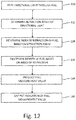
- FIG. 12 is a flow diagram illustrating example operations to determine a density of fuel contained in a fuel tank based on a determined index of refraction of the fuel.
- Directional light can be emitted from a light source through fuel contained in a fuel tank (Step 130).
- light source 70 can emit directed beam of light 78 through fuel contained in fuel tank 12.
- a refraction angle of the directional light after the directional light passes through an interface with the fuel can be determined (Step 132).
- controller 28 can determine angle ⁇ 2 , which can be considered a refraction angle of beam 78 after beam 78 passes through the interface with the fuel (e.g., fuel interface 74 separating ullage gases and fuel within fuel tank 12).
- An index of refraction of the fuel can be determined based on the determined refraction angle (Step 134).
- controller 28 can utilize Snell's law to determine the index of refraction of the fuel.
- a density of the fuel can be determined based on the determined index of refraction of the fuel (Step 136). For instance, controller 28 can determine the index of refraction based on angle ⁇ 2 as well as known properties of the fuel and a sensed temperature of the fuel (e.g., sensed via a thermal imager and/or temperature probe disposed within fuel tank 12).
- a fuel measurement value representing an amount of fuel contained in the fuel tank can be produced based on the determined density of the fuel (Step 138).
- controller 28 can determine a fuel measurement value representing a mass of fuel contained in fuel tank 12 based on the determined density and a determined volume of the fuel contained in fuel tank 12. An indication of the fuel measurement value can be output. For instance, controller 28 can output data including the fuel measurement value via one or more communication data buses.
- FIG. 13 is a flow diagram illustrating example operations to determine a chemical composition of a fuel tank ullage based on an amount of absorption of at least one wavelength of light transmitted through the fuel tank ullage.
- Light can be transmitted through a fuel tank ullage (Step 142).
- light source 90 can emit light through a distance of ullage gases 96 of fuel tank 12.
- An amount of absorption of at least one wavelength of the transmitted light can be determined (Step 144).
- controller 28 can determine, based on an intensity of light received by imagers 90 and/or 102, an absorption of at least one wavelength of the transmitted light.
- a chemical composition of the fuel tank ullage can be determined (Step 146).
- controller 28 can determine a presence and/or amount of a constituent of ullage gases 96 (e.g., oxygen gas, nitrogen gas, or other constituent) based on the amount of absorption of the at least one wavelength of the transmitted light.
- Controller 28 can, in certain examples, determine an operational status of an inert gas generating system configured to generate oxygen-depleted air for the fuel tank ullage based on the determined amount of absorption of the at least one wavelength of the transmitted light, such as an operational status corresponding to a failure mode of the inert gas generating system based on the presence and/or amount of a constituent of ullage gases 96.
- controller 28 can determine the failure mode of the inert gas generating system in response to determining that the amount of the constituent present in the ullage gases 96 deviates from one or more threshold acceptability criteria, such as a maximum limit corresponding to a maximum acceptable amount of the constituent (e.g., a maximum amount of oxygen gas), a minimum limit corresponding to a minimum acceptable amount of the constituent (e.g., a minimum amount of an inert gas, such as nitrogen gas), or other threshold acceptability criteria.
- a maximum limit corresponding to a maximum acceptable amount of the constituent e.g., a maximum amount of oxygen gas
- a minimum limit corresponding to a minimum acceptable amount of the constituent e.g., a minimum amount of an inert gas, such as nitrogen gas
- other threshold acceptability criteria such as a maximum limit corresponding to a maximum acceptable amount of the constituent (e.g., a maximum amount of oxygen gas), a minimum limit corresponding to a minimum acceptable amount of the constituent (e.g., a minimum amount
- Controller 28 can output, in some examples, the operational status of the inert gas generating system (e.g., an operational status corresponding to a failure mode and/or to a non-failure mode) to, e.g., one or more consuming systems, such as a data concentrator unit, an air conditioning system, cockpit displays, or other consuming system(s). Accordingly, controller 28 can help to increase system safety by determining and, e.g., outputting the operational status of the inert gas generating system. In some examples, the determined chemical composition can be used to activate and/or deactivate the inert gas generating system.
- controller 28 determines that an amount of a constituent, such as an inert gas constituent (e.g., nitrogen), satisfies threshold criteria, the inert gas generating system can be turned off or otherwise cease to provide inert gas for the fuel tank ullage.
- a constituent such as an inert gas constituent (e.g., nitrogen)
- the inert gas generating system can be turned off or otherwise cease to provide inert gas for the fuel tank ullage.
- techniques of this disclosure can help to decrease an amount of power (e.g., electrical power) consumed by an inert gas generating system, thereby increasing system efficiency.
- a fuel tank monitoring system 10 can utilize image processing techniques to determine properties of fuel tank 12, such as physical features of an interior of fuel tank 12 (e.g., locations and/or physical contours of spars 22, ribs 24, structural elements 26, or other physical features of the interior of fuel tank 12), a level and/or volume of fuel within the interior of fuel tank 12, tilt of an aircraft that includes fuel tank 12, an amount of bend of wing 14 of the aircraft, a density of the fuel within fuel tank 12, a chemical composition of fluids within fuel tank 12 (e.g., fuel, gases within an ullage of fuel tank 12, or other fluids within fuel tank 12), and/or a temperature of fluid(s) within fuel tank 12.
- properties of fuel tank 12 such as physical features of an interior of fuel tank 12 (e.g., locations and/or physical contours of spars 22, ribs 24, structural elements 26, or other physical features of the interior of fuel tank 12), a level and/or volume of fuel within the interior of fuel tank 12, tilt of an aircraft that includes fuel tank 12, an amount of bend of wing 14 of
- the techniques can enable such properties to be determined without the use of in-tank capacitive probes, thereby helping to decrease a number of electrical components installed within an interior of fuel tank 12. Moreover, techniques described herein can decrease a total number of installed components, thereby helping to reduce installation and maintenance costs associated with operation of fuel tank monitoring system 10.
Landscapes
- Physics & Mathematics (AREA)
- Engineering & Computer Science (AREA)
- General Physics & Mathematics (AREA)
- Fluid Mechanics (AREA)
- Electromagnetism (AREA)
- Aviation & Aerospace Engineering (AREA)
- Signal Processing (AREA)
- Computer Vision & Pattern Recognition (AREA)
- Theoretical Computer Science (AREA)
- Geometry (AREA)
- Thermal Sciences (AREA)
- Mechanical Engineering (AREA)
- Measurement Of Levels Of Liquids Or Fluent Solid Materials (AREA)
- Combined Controls Of Internal Combustion Engines (AREA)
- Fuel Cell (AREA)
- Monitoring And Testing Of Nuclear Reactors (AREA)
Claims (9)
- Procédé comprenant :la génération (104) de données d'image de référence représentant un champ de visualisation d'un intérieur d'un réservoir de carburant (12) ;la génération (106) de données d'image active représentant le champ de visualisation de l'intérieur du réservoir de carburant (12) lorsque le réservoir de carburant (12) contient du carburant ;la production (108), par un dispositif de traitement, d'une valeur de mesure de carburant représentant une quantité de carburant contenue dans le réservoir de carburant (12) sur la base des données d'image de référence et des données d'image active ; etla sortie (110), par le dispositif de traitement, d'une indication de la valeur de mesure de carburant ;dans lequel la production de la valeur de mesure de carburant comprend :l'identification, sur la base des données d'image de référence, de caractéristiques physiques de l'intérieur du réservoir de carburant (12) ;l'identification, sur la base des données d'image active, d'un emplacement de l'intérieur du réservoir de carburant (12) correspondant à une interface de carburant et de vide au sein de l'intérieur du réservoir de carburant (12) ; caractérisé en ce que le procédé comprend en outre :l'identification d'un emplacement de l'intérieur du réservoir de carburant (12) correspondant à une intersection de l'interface de carburant et de vide avec une ou plusieurs des caractéristiques physiques de l'intérieur du réservoir de carburant (12) ; etla production de la valeur de mesure de carburant sur la base de l'emplacement de l'intérieur du réservoir de carburant correspondant à l'intersection de l'interface de carburant et de vide avec les une ou plusieurs des caractéristiques physiques de l'intérieur du réservoir de carburant (12) comprenantla détermination, sur la base d'un modèle d'une forme du réservoir de carburant (12), d'un volume de carburant contenu au sein du réservoir de carburant (12) ; comprenant en outre :la détermination d'une forme ajustée du réservoir de carburant (12) sur la base des données d'image active en utilisant un modèle de la forme du réservoir de carburant (12) ;dans lequel la production de la valeur de mesure de carburant comprend la détermination du volume de carburant au sein du réservoir de carburant (12) sur la base de la forme ajustée du réservoir de carburant (12) ;dans lequel le réservoir de carburant est disposé au sein d'une aile de l'aéronef ; etdans lequel la détermination de la forme ajustée du réservoir de carburant (12) comprend la détermination d'une amplitude de flexion d'aile de l'aile de l'aéronef,dans lequel la détermination de l'amplitude de flexion d'aile de l'aile de l'aéronef comprend :la détermination d'un déplacement des au moins une ou plusieurs des caractéristiques physiques entre les données d'image de référence et les données d'image active ; etla détermination de l'amplitude de flexion d'aile sur la base du déplacement déterminé des une ou plusieurs des caractéristiques physiques.
- Procédé selon la revendication 1,
dans lequel la génération des données d'image de référence comprend la génération des données d'image de référence lorsque le réservoir de carburant (12) est vide de carburant. - Procédé selon une quelconque revendication précédente, dans lequel la génération des données d'image active représentant le champ de visualisation de l'intérieur du réservoir de carburant (12) comprend la génération de premières données d'image active représentant un premier champ de visualisation de l'intérieur du réservoir de carburant, le procédé comprenant en outre :la génération de secondes données d'image active représentant un second champ de visualisation de l'intérieur du réservoir de carburant (12) lorsque le réservoir de carburant contient du carburant ;dans lequel la production de la valeur de mesure de carburant comprend la production de la valeur de mesure de carburant représentant la quantité de carburant contenue dans le réservoir de carburant (12) sur la base des données d'image de référence et des premières et secondes données d'image active.
- Procédé selon la revendication 3,
dans lequel le premier champ de visualisation de l'intérieur du réservoir de carburant inclut une partie supérieure de l'intérieur du réservoir de carburant ;
dans lequel le second champ de visualisation de l'intérieur du réservoir de carburant inclut une partie inférieure de l'intérieur du réservoir de carburant ;
dans lequel la génération des premières données d'image active comprend la génération des premières données d'image active en utilisant un dispositif de capture d'image disposé au niveau de la partie inférieure de l'intérieur du réservoir de carburant ; et
dans lequel la génération des secondes données d'image active comprend la génération des secondes données d'image en utilisant un dispositif de capture d'image disposé au niveau de la partie supérieure de l'intérieur du réservoir de carburant. - Procédé selon la revendication 4,
dans lequel la génération des premières données d'image représentant le premier champ de visualisation incluant la partie supérieure de l'intérieur du réservoir de carburant comprend l'éclairage de l'intérieur du réservoir de carburant en utilisant une source de lumière disposée au niveau de la partie supérieure de l'intérieur du réservoir de carburant (12) ou
dans lequel la génération des premières données d'image active représentant le premier champ de visualisation incluant la partie supérieure de l'intérieur du réservoir de carburant comprend l'éclairage de l'intérieur du réservoir de carburant en utilisant une source de lumière disposée au niveau de la partie inférieure de l'intérieur du réservoir de carburant. - Procédé selon la revendication 4,
dans lequel la génération des secondes données d'image active représentant le second champ de visualisation incluant la partie inférieure de l'intérieur du réservoir de carburant comprend l'éclairage de l'intérieur du réservoir de carburant en utilisant une source de lumière disposée au niveau de la partie inférieure de l'intérieur du réservoir de carburant, ou
dans lequel la génération des secondes données d'image active représentant le second champ de visualisation incluant la partie inférieure de l'intérieur du réservoir de carburant comprend l'éclairage de l'intérieur du réservoir de carburant (12) en utilisant une source de lumière disposée au niveau de la partie supérieure de l'intérieur du réservoir de carburant. - Procédé selon la revendication 1,
dans lequel la génération des données d'image active comprend la génération des données d'image active en utilisant un ou plusieurs dispositifs de capture d'image disposés au sein d'un intérieur du réservoir de carburant (12), ou
dans lequel la génération des données d'image active comprend la génération des données d'image active en utilisant un ou plusieurs dispositifs de capture d'image disposés à l'extérieur de l'intérieur du réservoir de carburant (12). - Système comprenant :
un ou plusieurs dispositifs de capture d'image placés pour :générer (104) des données d'image de référence représentatives d'un intérieur d'un réservoir de carburant ; etgénérer (106) des données d'image active de l'intérieur du réservoir de carburant lorsque le réservoir de carburant contient du carburant ;au moins un processeur ; etune mémoire lisible par un ordinateur codée avec des instructions qui, lorsqu'elles sont exécutées par l'au moins un processeur, amènent le système à :produire (108) une valeur de mesure de carburant représentant une quantité de carburant contenue dans le réservoir de carburant sur la base des données d'image de référence et des données d'image active ; etsortir (110) une indication de la valeur de mesure de carburant,dans lequel la mémoire lisible par un ordinateur est en outre codée avec des instructions qui, lorsqu'elles sont exécutées par l'au moins un processeur, amènent le système à produire la valeur de mesure de carburant en amenant au moins le système à :identifier, sur la base des données d'image de référence, des caractéristiques physiques de l'intérieur du réservoir de carburant (12) ;identifier, sur la base des données d'image active, un emplacement de l'intérieur du réservoir de carburant correspondant à une interface de carburant et de vide au sein de l'intérieur du réservoir de carburant (12) ; caractérisé en ce que la mémoire lisible par un ordinateur est en outre codée avec des instructions qui, lorsqu'elles sont exécutées par l'au moins un processeur, amènent le système à produire la valeur de mesure de carburant en amenant au moins le système à :identifier un emplacement de l'intérieur du réservoir de carburant correspondant à une intersection de l'interface de carburant et de vide avec une ou plusieurs des caractéristiques physiques de l'intérieur du réservoir de carburant (12) ;produire la valeur de mesure de carburant sur la base de l'emplacement de l'intérieur du réservoir de carburant correspondant à l'intersection de l'interface de carburant et de vide avec les au moins une ou plusieurs des caractéristiques physiques de l'intérieur du réservoir de carburant (12), en amenant le système àdéterminer, sur la base d'un modèle d'une forme du réservoir de carburant (12), un volume de carburant contenu au sein du réservoir de carburant ;dans lequel le réservoir de carburant est disposé au sein d'une aile de l'aéronef ; etdans lequel la mémoire lisible par un ordinateur est en outre codée avec des instructions qui, lorsqu'elles sont exécutées par l'au moins un processeur, amènent le système à :déterminer une amplitude de flexion d'aile de l'aile de l'aéronef ;déterminer une forme ajustée du réservoir de carburant sur la base de l'amplitude déterminée de flexion d'aile en utilisant un modèle de la forme du réservoir de carburant (12) ; etproduire la valeur de mesure de carburant en déterminant au moins le volume de carburant au sein du réservoir de carburant sur la base de la forme ajustée du réservoir de carburant. - Système selon la revendication 8,
dans lequel les données d'image active de l'intérieur du réservoir de carburant (12) comprennent des premières données d'image active représentant un premier champ de visualisation de l'intérieur du réservoir de carburant (12) ;
dans lequel les un ou plusieurs dispositifs de capture d'image sont en outre placés pour générer des secondes données d'image active de l'intérieur du réservoir de carburant lorsque le réservoir de carburant contient du carburant ; et
dans lequel la mémoire lisible par un ordinateur est en outre codée avec des instructions qui, lorsqu'elles sont exécutées par l'au moins un processeur, amènent le système à produire la valeur de mesure de carburant en amenant au moins le système à produire la valeur de mesure de carburant sur la base des données d'image de référence et des premières et secondes données d'image active.
Applications Claiming Priority (1)
| Application Number | Priority Date | Filing Date | Title |
|---|---|---|---|
| US15/015,827 US10424076B2 (en) | 2016-02-04 | 2016-02-04 | Imaging system for fuel tank analysis |
Publications (2)
| Publication Number | Publication Date |
|---|---|
| EP3205986A1 EP3205986A1 (fr) | 2017-08-16 |
| EP3205986B1 true EP3205986B1 (fr) | 2020-04-15 |
Family
ID=57965847
Family Applications (1)
| Application Number | Title | Priority Date | Filing Date |
|---|---|---|---|
| EP17154843.1A Active EP3205986B1 (fr) | 2016-02-04 | 2017-02-06 | Système d'imagerie pour analyse de réservoir de carburant |
Country Status (4)
| Country | Link |
|---|---|
| US (1) | US10424076B2 (fr) |
| EP (1) | EP3205986B1 (fr) |
| BR (1) | BR102017000152B1 (fr) |
| CA (1) | CA2948757C (fr) |
Families Citing this family (6)
| Publication number | Priority date | Publication date | Assignee | Title |
|---|---|---|---|---|
| US10627280B2 (en) * | 2017-04-17 | 2020-04-21 | Simmonds Precision Products | Integrated sensor unit for fuel gauging |
| EP3556662B1 (fr) | 2018-04-20 | 2022-10-12 | Goodrich Lighting Systems GmbH | Lumière d'éclairage d'un stabilisateur vertical d'un aéronef et procédé de fonctionnement d'une lumière d'éclairage d'un stabilisateur vertical d'un aéronef |
| DE102018208630A1 (de) * | 2018-05-30 | 2019-12-05 | Fraunhofer-Gesellschaft zur Förderung der angewandten Forschung e.V. | Vorrichtung und verfahren zur überwachung eines behälterfüllstands und computerprogramm |
| US11649056B2 (en) * | 2020-06-17 | 2023-05-16 | Honeywell International Inc. | Thermally isolated sensor for gas turbine engine |
| US11787555B2 (en) * | 2021-08-13 | 2023-10-17 | The Boeing Company | Fuel dams, aircraft wing boxes, aircraft, and methods of assembling aircraft wings |
| US12546269B2 (en) * | 2023-06-30 | 2026-02-10 | Torc Robotics, Inc. | Systems and methods of detecting fluid release |
Family Cites Families (44)
| Publication number | Priority date | Publication date | Assignee | Title |
|---|---|---|---|---|
| US4420976A (en) | 1981-09-09 | 1983-12-20 | Mcdonnell Douglas Corporation | Multiplexed true mass gaging system |
| US7164117B2 (en) | 1992-05-05 | 2007-01-16 | Automotive Technologies International, Inc. | Vehicular restraint system control system and method using multiple optical imagers |
| US5138559A (en) * | 1989-08-28 | 1992-08-11 | The Boeing Company | System and method for measuring liquid mass quantity |
| JPH0493639A (ja) | 1990-08-03 | 1992-03-26 | Mitsubishi Electric Corp | 燃料性状検知装置 |
| GB2289542B (en) | 1994-05-09 | 1998-08-26 | Automotive Tech Int | Method and apparatus for measuring the quantity of fuel in a land vehicle fuel tank subject to external forces |
| US6892572B2 (en) | 1994-05-09 | 2005-05-17 | Automotive Technologies International, Inc. | Method and apparatus for measuring the quantity of a liquid in a vehicle container |
| US6098029A (en) | 1994-06-14 | 2000-08-01 | Hitachi, Ltd. | Liquid-level position measuring method and system |
| US7738678B2 (en) | 1995-06-07 | 2010-06-15 | Automotive Technologies International, Inc. | Light modulation techniques for imaging objects in or around a vehicle |
| US20060284839A1 (en) | 1999-12-15 | 2006-12-21 | Automotive Technologies International, Inc. | Vehicular Steering Wheel with Input Device |
| US6136267A (en) | 1998-05-26 | 2000-10-24 | Bergman Consulting Engineers | Fuel ignition arrester system and method |
| JP3583659B2 (ja) | 1999-08-04 | 2004-11-04 | 富士通株式会社 | 液面検出方式 |
| AU2001237053A1 (en) | 2000-02-17 | 2001-08-27 | Bintech. Lllp | Bulk materials management apparatus and method |
| US6782122B1 (en) | 2000-04-27 | 2004-08-24 | Simmonds Precision Products, Inc. | Apparatus for measuring height of a liquid in a container using area image pattern recognition techniques |
| US7819003B2 (en) | 2002-06-11 | 2010-10-26 | Intelligent Technologies International, Inc. | Remote monitoring of fluid storage tanks |
| US9625361B1 (en) | 2001-08-19 | 2017-04-18 | Smart Drilling And Completion, Inc. | Methods and apparatus to prevent failures of fiber-reinforced composite materials under compressive stresses caused by fluids and gases invading microfractures in the materials |
| US6698692B1 (en) | 2002-01-04 | 2004-03-02 | Clyde L. Tichenor | Aircraft fuel tank ullage safety system |
| EP1633627A1 (fr) | 2003-06-16 | 2006-03-15 | Siemens Aktiengesellschaft | Dispositif et procede pour la surveillance de la concentration en oxygene dans un reservoir d'aeronef |
| US7352464B2 (en) | 2004-01-05 | 2008-04-01 | Southwest Sciences Incorporated | Oxygen sensor for aircraft fuel inerting systems |
| GB0521800D0 (en) | 2005-10-26 | 2005-12-07 | Trw Ltd | Optical fluid level detector |
| US7385692B1 (en) | 2006-04-28 | 2008-06-10 | The United Of America As Represented By The Administrator Of Nasa | Method and system for fiber optic determination of gas concentrations in liquid receptacles |
| JP4948117B2 (ja) | 2006-10-23 | 2012-06-06 | トヨタ自動車株式会社 | 燃料性状検出装置 |
| US8141819B2 (en) | 2007-04-09 | 2012-03-27 | Raytheon Company | Modular aircraft with removable spar |
| US8081313B2 (en) | 2007-05-24 | 2011-12-20 | Airbus Operations Limited | Method and apparatus for monitoring gas concentration in a fluid |
| JP2010540942A (ja) | 2007-10-01 | 2010-12-24 | バイブロ−メーター インコーポレイテッド | 容器中の流体レベルを正確に測定するシステムおよび方法 |
| US8452046B2 (en) | 2008-10-07 | 2013-05-28 | Honeywell International Inc. | Method and apparatus for automatic sediment or sludge detection, monitoring, and inspection in oil storage and other facilities |
| DE102009007935B4 (de) | 2009-02-06 | 2011-06-30 | Lewandowski, Angela, 30159 | Vorrichtung und Verfahren für die künstliche Verlängerung von Nägeln |
| US9429957B2 (en) | 2009-03-06 | 2016-08-30 | GM Global Technology Operations LLC | Variable capacity fuel tank |
| JP5183541B2 (ja) | 2009-03-23 | 2013-04-17 | 愛三工業株式会社 | 燃料性状判定装置 |
| US8184848B2 (en) | 2009-06-17 | 2012-05-22 | National Applied Research Laboratories | Liquid level detection method |
| CN102467846A (zh) | 2011-05-22 | 2012-05-23 | 杨兆民 | 介质折射率测定装置 |
| US9068875B1 (en) * | 2011-06-26 | 2015-06-30 | Alvin R. Wirthlin | Optical liquid level transducer |
| TWI473976B (zh) | 2013-06-28 | 2015-02-21 | Univ Nat Taiwan Ocean | 液面高度量測模組 |
| US9528871B2 (en) | 2013-11-13 | 2016-12-27 | Deere & Company | System for determining a liquid quantity and orientation |
| US9459130B2 (en) | 2013-11-13 | 2016-10-04 | Deere & Company | System for measuring a liquid level and orientation |
| GB2520721A (en) | 2013-11-29 | 2015-06-03 | Airbus Operations Ltd | Fuel surface height measurement |
| US9098753B1 (en) | 2014-04-25 | 2015-08-04 | Google Inc. | Methods and systems for object detection using multiple sensors |
| US9340106B2 (en) | 2014-04-29 | 2016-05-17 | Ford Global Technologies, Llc | Systems and methods for an externally accessible refueling request switch |
| JP2017530486A (ja) * | 2014-07-07 | 2017-10-12 | エクスパートシー ソリューションズ インク | 生物を有する試料の関心変数の値を決定する方法及びそのシステム |
| US9459205B1 (en) | 2015-04-27 | 2016-10-04 | Empire Technology Development Llc | Refractive index measurement of liquids over a broad spectral range |
| GB2538539A (en) * | 2015-05-20 | 2016-11-23 | Airbus Operations Ltd | Measuring surface of a liquid |
| GB2539909A (en) | 2015-06-30 | 2017-01-04 | Airbus Operations Ltd | Aircraft fuel measurement |
| DE102015117384B4 (de) * | 2015-10-14 | 2023-01-05 | Analytik Jena Gmbh | Verfahren zur spektralen Analyse von Proben mittels Graphitrohr |
| JP6553487B2 (ja) * | 2015-11-10 | 2019-07-31 | 株式会社Screenホールディングス | 吐出判定方法および吐出装置 |
| US9978137B2 (en) | 2016-02-04 | 2018-05-22 | Simmonds Precision Products, Inc. | Imaging system for fuel tank analysis |
-
2016
- 2016-02-04 US US15/015,827 patent/US10424076B2/en active Active
- 2016-11-16 CA CA2948757A patent/CA2948757C/fr active Active
-
2017
- 2017-01-04 BR BR102017000152-0A patent/BR102017000152B1/pt active IP Right Grant
- 2017-02-06 EP EP17154843.1A patent/EP3205986B1/fr active Active
Non-Patent Citations (1)
| Title |
|---|
| None * |
Also Published As
| Publication number | Publication date |
|---|---|
| US20170228881A1 (en) | 2017-08-10 |
| CA2948757C (fr) | 2023-09-26 |
| US10424076B2 (en) | 2019-09-24 |
| BR102017000152B1 (pt) | 2022-11-16 |
| BR102017000152A2 (pt) | 2017-08-08 |
| EP3205986A1 (fr) | 2017-08-16 |
| CA2948757A1 (fr) | 2017-08-04 |
Similar Documents
| Publication | Publication Date | Title |
|---|---|---|
| EP3203199B1 (fr) | Système d'imagerie pour analyse de réservoir de carburant | |
| EP3205986B1 (fr) | Système d'imagerie pour analyse de réservoir de carburant | |
| EP3203200B1 (fr) | Système d'imagerie d'analyse de réservoir de carburant | |
| EP3203196B1 (fr) | Système d'imagerie pour analyse de réservoir de carburant | |
| US12111335B2 (en) | Measurement of gas flow rate | |
| CN106168503B (zh) | 测量液体的表面 | |
| CA2948739C (fr) | Systeme d'imagerie destine a l'analyse de reservoir de carburant | |
| US20060115113A1 (en) | Method for the recognition and tracking of objects | |
| CN111750821B (zh) | 一种位姿参数测量方法、装置、系统和存储介质 | |
| CN115552280A (zh) | 物体检测系统以及物体检测方法 |
Legal Events
| Date | Code | Title | Description |
|---|---|---|---|
| PUAI | Public reference made under article 153(3) epc to a published international application that has entered the european phase |
Free format text: ORIGINAL CODE: 0009012 |
|
| STAA | Information on the status of an ep patent application or granted ep patent |
Free format text: STATUS: THE APPLICATION HAS BEEN PUBLISHED |
|
| AK | Designated contracting states |
Kind code of ref document: A1 Designated state(s): AL AT BE BG CH CY CZ DE DK EE ES FI FR GB GR HR HU IE IS IT LI LT LU LV MC MK MT NL NO PL PT RO RS SE SI SK SM TR |
|
| AX | Request for extension of the european patent |
Extension state: BA ME |
|
| STAA | Information on the status of an ep patent application or granted ep patent |
Free format text: STATUS: REQUEST FOR EXAMINATION WAS MADE |
|
| 17P | Request for examination filed |
Effective date: 20180208 |
|
| RBV | Designated contracting states (corrected) |
Designated state(s): AL AT BE BG CH CY CZ DE DK EE ES FI FR GB GR HR HU IE IS IT LI LT LU LV MC MK MT NL NO PL PT RO RS SE SI SK SM TR |
|
| STAA | Information on the status of an ep patent application or granted ep patent |
Free format text: STATUS: EXAMINATION IS IN PROGRESS |
|
| 17Q | First examination report despatched |
Effective date: 20180918 |
|
| GRAP | Despatch of communication of intention to grant a patent |
Free format text: ORIGINAL CODE: EPIDOSNIGR1 |
|
| STAA | Information on the status of an ep patent application or granted ep patent |
Free format text: STATUS: GRANT OF PATENT IS INTENDED |
|
| RIC1 | Information provided on ipc code assigned before grant |
Ipc: G06T 7/62 20170101ALI20190603BHEP Ipc: B64C 37/00 20060101ALI20190603BHEP Ipc: G01F 23/00 20060101ALI20190603BHEP Ipc: G01F 23/292 20060101ALI20190603BHEP Ipc: B64C 3/34 20060101ALI20190603BHEP Ipc: B64D 37/00 20060101ALI20190603BHEP Ipc: G01F 22/00 20060101AFI20190603BHEP Ipc: H04N 5/225 20060101ALI20190603BHEP |
|
| INTG | Intention to grant announced |
Effective date: 20190621 |
|
| GRAJ | Information related to disapproval of communication of intention to grant by the applicant or resumption of examination proceedings by the epo deleted |
Free format text: ORIGINAL CODE: EPIDOSDIGR1 |
|
| STAA | Information on the status of an ep patent application or granted ep patent |
Free format text: STATUS: EXAMINATION IS IN PROGRESS |
|
| GRAP | Despatch of communication of intention to grant a patent |
Free format text: ORIGINAL CODE: EPIDOSNIGR1 |
|
| STAA | Information on the status of an ep patent application or granted ep patent |
Free format text: STATUS: GRANT OF PATENT IS INTENDED |
|
| INTG | Intention to grant announced |
Effective date: 20191107 |
|
| GRAS | Grant fee paid |
Free format text: ORIGINAL CODE: EPIDOSNIGR3 |
|
| GRAA | (expected) grant |
Free format text: ORIGINAL CODE: 0009210 |
|
| STAA | Information on the status of an ep patent application or granted ep patent |
Free format text: STATUS: THE PATENT HAS BEEN GRANTED |
|
| AK | Designated contracting states |
Kind code of ref document: B1 Designated state(s): AL AT BE BG CH CY CZ DE DK EE ES FI FR GB GR HR HU IE IS IT LI LT LU LV MC MK MT NL NO PL PT RO RS SE SI SK SM TR |
|
| REG | Reference to a national code |
Ref country code: CH Ref legal event code: EP |
|
| REG | Reference to a national code |
Ref country code: DE Ref legal event code: R096 Ref document number: 602017014616 Country of ref document: DE |
|
| REG | Reference to a national code |
Ref country code: IE Ref legal event code: FG4D |
|
| REG | Reference to a national code |
Ref country code: AT Ref legal event code: REF Ref document number: 1257862 Country of ref document: AT Kind code of ref document: T Effective date: 20200515 |
|
| REG | Reference to a national code |
Ref country code: NL Ref legal event code: MP Effective date: 20200415 |
|
| REG | Reference to a national code |
Ref country code: LT Ref legal event code: MG4D |
|
| PG25 | Lapsed in a contracting state [announced via postgrant information from national office to epo] |
Ref country code: LT Free format text: LAPSE BECAUSE OF FAILURE TO SUBMIT A TRANSLATION OF THE DESCRIPTION OR TO PAY THE FEE WITHIN THE PRESCRIBED TIME-LIMIT Effective date: 20200415 Ref country code: PT Free format text: LAPSE BECAUSE OF FAILURE TO SUBMIT A TRANSLATION OF THE DESCRIPTION OR TO PAY THE FEE WITHIN THE PRESCRIBED TIME-LIMIT Effective date: 20200817 Ref country code: GR Free format text: LAPSE BECAUSE OF FAILURE TO SUBMIT A TRANSLATION OF THE DESCRIPTION OR TO PAY THE FEE WITHIN THE PRESCRIBED TIME-LIMIT Effective date: 20200716 Ref country code: NO Free format text: LAPSE BECAUSE OF FAILURE TO SUBMIT A TRANSLATION OF THE DESCRIPTION OR TO PAY THE FEE WITHIN THE PRESCRIBED TIME-LIMIT Effective date: 20200715 Ref country code: IS Free format text: LAPSE BECAUSE OF FAILURE TO SUBMIT A TRANSLATION OF THE DESCRIPTION OR TO PAY THE FEE WITHIN THE PRESCRIBED TIME-LIMIT Effective date: 20200815 Ref country code: FI Free format text: LAPSE BECAUSE OF FAILURE TO SUBMIT A TRANSLATION OF THE DESCRIPTION OR TO PAY THE FEE WITHIN THE PRESCRIBED TIME-LIMIT Effective date: 20200415 Ref country code: NL Free format text: LAPSE BECAUSE OF FAILURE TO SUBMIT A TRANSLATION OF THE DESCRIPTION OR TO PAY THE FEE WITHIN THE PRESCRIBED TIME-LIMIT Effective date: 20200415 Ref country code: SE Free format text: LAPSE BECAUSE OF FAILURE TO SUBMIT A TRANSLATION OF THE DESCRIPTION OR TO PAY THE FEE WITHIN THE PRESCRIBED TIME-LIMIT Effective date: 20200415 |
|
| REG | Reference to a national code |
Ref country code: AT Ref legal event code: MK05 Ref document number: 1257862 Country of ref document: AT Kind code of ref document: T Effective date: 20200415 |
|
| PG25 | Lapsed in a contracting state [announced via postgrant information from national office to epo] |
Ref country code: HR Free format text: LAPSE BECAUSE OF FAILURE TO SUBMIT A TRANSLATION OF THE DESCRIPTION OR TO PAY THE FEE WITHIN THE PRESCRIBED TIME-LIMIT Effective date: 20200415 Ref country code: BG Free format text: LAPSE BECAUSE OF FAILURE TO SUBMIT A TRANSLATION OF THE DESCRIPTION OR TO PAY THE FEE WITHIN THE PRESCRIBED TIME-LIMIT Effective date: 20200715 Ref country code: RS Free format text: LAPSE BECAUSE OF FAILURE TO SUBMIT A TRANSLATION OF THE DESCRIPTION OR TO PAY THE FEE WITHIN THE PRESCRIBED TIME-LIMIT Effective date: 20200415 Ref country code: LV Free format text: LAPSE BECAUSE OF FAILURE TO SUBMIT A TRANSLATION OF THE DESCRIPTION OR TO PAY THE FEE WITHIN THE PRESCRIBED TIME-LIMIT Effective date: 20200415 |
|
| PG25 | Lapsed in a contracting state [announced via postgrant information from national office to epo] |
Ref country code: AL Free format text: LAPSE BECAUSE OF FAILURE TO SUBMIT A TRANSLATION OF THE DESCRIPTION OR TO PAY THE FEE WITHIN THE PRESCRIBED TIME-LIMIT Effective date: 20200415 |
|
| REG | Reference to a national code |
Ref country code: DE Ref legal event code: R097 Ref document number: 602017014616 Country of ref document: DE |
|
| PG25 | Lapsed in a contracting state [announced via postgrant information from national office to epo] |
Ref country code: ES Free format text: LAPSE BECAUSE OF FAILURE TO SUBMIT A TRANSLATION OF THE DESCRIPTION OR TO PAY THE FEE WITHIN THE PRESCRIBED TIME-LIMIT Effective date: 20200415 Ref country code: AT Free format text: LAPSE BECAUSE OF FAILURE TO SUBMIT A TRANSLATION OF THE DESCRIPTION OR TO PAY THE FEE WITHIN THE PRESCRIBED TIME-LIMIT Effective date: 20200415 Ref country code: DK Free format text: LAPSE BECAUSE OF FAILURE TO SUBMIT A TRANSLATION OF THE DESCRIPTION OR TO PAY THE FEE WITHIN THE PRESCRIBED TIME-LIMIT Effective date: 20200415 Ref country code: EE Free format text: LAPSE BECAUSE OF FAILURE TO SUBMIT A TRANSLATION OF THE DESCRIPTION OR TO PAY THE FEE WITHIN THE PRESCRIBED TIME-LIMIT Effective date: 20200415 Ref country code: SM Free format text: LAPSE BECAUSE OF FAILURE TO SUBMIT A TRANSLATION OF THE DESCRIPTION OR TO PAY THE FEE WITHIN THE PRESCRIBED TIME-LIMIT Effective date: 20200415 Ref country code: CZ Free format text: LAPSE BECAUSE OF FAILURE TO SUBMIT A TRANSLATION OF THE DESCRIPTION OR TO PAY THE FEE WITHIN THE PRESCRIBED TIME-LIMIT Effective date: 20200415 Ref country code: RO Free format text: LAPSE BECAUSE OF FAILURE TO SUBMIT A TRANSLATION OF THE DESCRIPTION OR TO PAY THE FEE WITHIN THE PRESCRIBED TIME-LIMIT Effective date: 20200415 Ref country code: IT Free format text: LAPSE BECAUSE OF FAILURE TO SUBMIT A TRANSLATION OF THE DESCRIPTION OR TO PAY THE FEE WITHIN THE PRESCRIBED TIME-LIMIT Effective date: 20200415 |
|
| PLBE | No opposition filed within time limit |
Free format text: ORIGINAL CODE: 0009261 |
|
| STAA | Information on the status of an ep patent application or granted ep patent |
Free format text: STATUS: NO OPPOSITION FILED WITHIN TIME LIMIT |
|
| PG25 | Lapsed in a contracting state [announced via postgrant information from national office to epo] |
Ref country code: PL Free format text: LAPSE BECAUSE OF FAILURE TO SUBMIT A TRANSLATION OF THE DESCRIPTION OR TO PAY THE FEE WITHIN THE PRESCRIBED TIME-LIMIT Effective date: 20200415 Ref country code: SK Free format text: LAPSE BECAUSE OF FAILURE TO SUBMIT A TRANSLATION OF THE DESCRIPTION OR TO PAY THE FEE WITHIN THE PRESCRIBED TIME-LIMIT Effective date: 20200415 |
|
| 26N | No opposition filed |
Effective date: 20210118 |
|
| PG25 | Lapsed in a contracting state [announced via postgrant information from national office to epo] |
Ref country code: SI Free format text: LAPSE BECAUSE OF FAILURE TO SUBMIT A TRANSLATION OF THE DESCRIPTION OR TO PAY THE FEE WITHIN THE PRESCRIBED TIME-LIMIT Effective date: 20200415 |
|
| PG25 | Lapsed in a contracting state [announced via postgrant information from national office to epo] |
Ref country code: MC Free format text: LAPSE BECAUSE OF FAILURE TO SUBMIT A TRANSLATION OF THE DESCRIPTION OR TO PAY THE FEE WITHIN THE PRESCRIBED TIME-LIMIT Effective date: 20200415 |
|
| REG | Reference to a national code |
Ref country code: BE Ref legal event code: MM Effective date: 20210228 |
|
| PG25 | Lapsed in a contracting state [announced via postgrant information from national office to epo] |
Ref country code: CH Free format text: LAPSE BECAUSE OF NON-PAYMENT OF DUE FEES Effective date: 20210228 Ref country code: LI Free format text: LAPSE BECAUSE OF NON-PAYMENT OF DUE FEES Effective date: 20210228 Ref country code: LU Free format text: LAPSE BECAUSE OF NON-PAYMENT OF DUE FEES Effective date: 20210206 |
|
| PG25 | Lapsed in a contracting state [announced via postgrant information from national office to epo] |
Ref country code: IE Free format text: LAPSE BECAUSE OF NON-PAYMENT OF DUE FEES Effective date: 20210206 |
|
| PG25 | Lapsed in a contracting state [announced via postgrant information from national office to epo] |
Ref country code: BE Free format text: LAPSE BECAUSE OF NON-PAYMENT OF DUE FEES Effective date: 20210228 |
|
| PG25 | Lapsed in a contracting state [announced via postgrant information from national office to epo] |
Ref country code: HU Free format text: LAPSE BECAUSE OF FAILURE TO SUBMIT A TRANSLATION OF THE DESCRIPTION OR TO PAY THE FEE WITHIN THE PRESCRIBED TIME-LIMIT; INVALID AB INITIO Effective date: 20170206 |
|
| PG25 | Lapsed in a contracting state [announced via postgrant information from national office to epo] |
Ref country code: CY Free format text: LAPSE BECAUSE OF FAILURE TO SUBMIT A TRANSLATION OF THE DESCRIPTION OR TO PAY THE FEE WITHIN THE PRESCRIBED TIME-LIMIT Effective date: 20200415 |
|
| PG25 | Lapsed in a contracting state [announced via postgrant information from national office to epo] |
Ref country code: MK Free format text: LAPSE BECAUSE OF FAILURE TO SUBMIT A TRANSLATION OF THE DESCRIPTION OR TO PAY THE FEE WITHIN THE PRESCRIBED TIME-LIMIT Effective date: 20200415 |
|
| PG25 | Lapsed in a contracting state [announced via postgrant information from national office to epo] |
Ref country code: MT Free format text: LAPSE BECAUSE OF FAILURE TO SUBMIT A TRANSLATION OF THE DESCRIPTION OR TO PAY THE FEE WITHIN THE PRESCRIBED TIME-LIMIT Effective date: 20200415 |
|
| PGFP | Annual fee paid to national office [announced via postgrant information from national office to epo] |
Ref country code: DE Payment date: 20250122 Year of fee payment: 9 |
|
| PGFP | Annual fee paid to national office [announced via postgrant information from national office to epo] |
Ref country code: FR Payment date: 20250122 Year of fee payment: 9 |
|
| PG25 | Lapsed in a contracting state [announced via postgrant information from national office to epo] |
Ref country code: TR Free format text: LAPSE BECAUSE OF FAILURE TO SUBMIT A TRANSLATION OF THE DESCRIPTION OR TO PAY THE FEE WITHIN THE PRESCRIBED TIME-LIMIT Effective date: 20200415 |
|
| PGFP | Annual fee paid to national office [announced via postgrant information from national office to epo] |
Ref country code: GB Payment date: 20260331 Year of fee payment: 10 |