EP3205994A1 - Drucksensor und vorrichtung - Google Patents
Drucksensor und vorrichtung Download PDFInfo
- Publication number
- EP3205994A1 EP3205994A1 EP17155611.1A EP17155611A EP3205994A1 EP 3205994 A1 EP3205994 A1 EP 3205994A1 EP 17155611 A EP17155611 A EP 17155611A EP 3205994 A1 EP3205994 A1 EP 3205994A1
- Authority
- EP
- European Patent Office
- Prior art keywords
- pressure sensor
- sensor
- face
- pressure
- present
- Prior art date
- Legal status (The legal status is an assumption and is not a legal conclusion. Google has not performed a legal analysis and makes no representation as to the accuracy of the status listed.)
- Granted
Links
Images

Classifications
-
- G—PHYSICS
- G01—MEASURING; TESTING
- G01L—MEASURING FORCE, STRESS, TORQUE, WORK, MECHANICAL POWER, MECHANICAL EFFICIENCY, OR FLUID PRESSURE
- G01L19/00—Details of, or accessories for, apparatus for measuring steady or quasi-steady pressure of a fluent medium insofar as such details or accessories are not special to particular types of pressure gauges
- G01L19/14—Housings
- G01L19/142—Multiple part housings
-
- G—PHYSICS
- G01—MEASURING; TESTING
- G01L—MEASURING FORCE, STRESS, TORQUE, WORK, MECHANICAL POWER, MECHANICAL EFFICIENCY, OR FLUID PRESSURE
- G01L9/00—Measuring steady of quasi-steady pressure of fluid or fluent solid material by electric or magnetic pressure-sensitive elements; Transmitting or indicating the displacement of mechanical pressure-sensitive elements, used to measure the steady or quasi-steady pressure of a fluid or fluent solid material, by electric or magnetic means
- G01L9/0041—Transmitting or indicating the displacement of flexible diaphragms
- G01L9/0051—Transmitting or indicating the displacement of flexible diaphragms using variations in ohmic resistance
- G01L9/0052—Transmitting or indicating the displacement of flexible diaphragms using variations in ohmic resistance of piezoresistive elements
-
- G—PHYSICS
- G01—MEASURING; TESTING
- G01L—MEASURING FORCE, STRESS, TORQUE, WORK, MECHANICAL POWER, MECHANICAL EFFICIENCY, OR FLUID PRESSURE
- G01L19/00—Details of, or accessories for, apparatus for measuring steady or quasi-steady pressure of a fluent medium insofar as such details or accessories are not special to particular types of pressure gauges
- G01L19/14—Housings
- G01L19/142—Multiple part housings
- G01L19/144—Multiple part housings with dismountable parts, e.g. for maintenance purposes or for ensuring sterile conditions
-
- G—PHYSICS
- G01—MEASURING; TESTING
- G01L—MEASURING FORCE, STRESS, TORQUE, WORK, MECHANICAL POWER, MECHANICAL EFFICIENCY, OR FLUID PRESSURE
- G01L19/00—Details of, or accessories for, apparatus for measuring steady or quasi-steady pressure of a fluent medium insofar as such details or accessories are not special to particular types of pressure gauges
- G01L19/14—Housings
- G01L19/147—Details about the mounting of the sensor to support or covering means
Definitions
- the present invention relates to a pressure sensor and an apparatus including the pressure sensor.
- infusion tubes that deliver infusion solutions such as chemical solutions and dialysates must be controlled so as not to be clogged during solution delivery operation.
- some pump apparatuses detect clogging of an infusion tube using a pressure sensor.
- a pump apparatus including such a pressure sensor maintenance work is required to be performed that dismounts the pressure sensor from the pump apparatus and cleans the pressure sensor in order to enable clogging of the infusion tube to be detected continuously with high precision.
- a structure of the pressure sensor mountable and dismountable on and from the apparatus is developed (refer to Japanese Laid-open Patent Publication No. 2007-315792 ).
- the present invention has been made in view of the above problem, and an object thereof is to provide a pressure sensor and an apparatus that can prevent a base of the pressure sensor from being broken by the application of side pressure to the base of the pressure sensor.
- the following first describes a configuration of a pump apparatus in which the pressure sensor as the first and the second embodiments of the present invention is used with reference to FIG. 1 .
- the field of application of the pressure sensor according to the present invention is not limited to the pump apparatus illustrated in FIG. 1 .
- FIG. 1 is a perspective view of the configuration of the pump apparatus in which the pressure sensor as the first and the second embodiments of the present invention is used.
- this pump apparatus 1 in which the pressure sensor as the first and the second embodiments of the present invention is used is an apparatus that delivers infusion solutions such as chemical solutions and dialysates and includes a housing 2 having a handle 2a on the top face thereof.
- the housing 2 houses a pump mechanism P, a controller that controls the operation of the pump apparatus 1, and the like.
- a control panel face 2b is formed on the left half part on the front of the housing 2.
- a pump mechanism arrangement face 2c is formed at a position retracted toward the back side on the right half part on the front of the housing 2.
- the control panel face 2b is provided with a plurality of switches for operating the pump apparatus 1 such as a power switch, a solution delivery start switch, a solution delivery end switch, a forced stop switch, and a warning sound/warning message stop switch.
- switches for operating the pump apparatus 1 such as a power switch, a solution delivery start switch, a solution delivery end switch, a forced stop switch, and a warning sound/warning message stop switch.
- the pump mechanism arrangement face 2c is provided with the pump mechanism P and a pressure sensor 3 as the first and the second embodiments of the present invention.
- the pressure sensor 3 is arranged at a position immediately below the pump mechanism P and on the back side of an elastic body 4.
- the elastic body 4 is formed of a flat, sheet-shaped or film-shaped elastic body.
- Tube guides 2d are provided at a plurality of places (three places in the example illustrated in FIG. 1 ) in an up-and-down direction of the pump mechanism arrangement face 2c.
- the tube guides 2d guide and hold an infusion tube T routed in the up-and-down direction through the pump mechanism P and a sensor face 3a of the pressure sensor 3 to and at a fixed place.
- the sensor face 3a is not necessarily flat.
- a door 2e that covers the pump mechanism arrangement face 2c is mounted on the housing 2.
- the door 2e is mounted on the housing 2 in an openable and closable manner through hinges 2f.
- a tube retainer plate 2g is mounted on the back of the door 2e.
- the tube retainer plate 2g is a retainer member that brings the infusion tube T into intimate contact with the pump mechanism P when the door 2e is closed to cause solution delivery operation to be normally performed.
- a tube retainer 2h is mounted on the back of the door 2e.
- the tube retainer 2h includes a tube retainer main body and a coil spring, which are not illustrated.
- the tube retainer 2h brings the infusion tube T, the elastic body 4, and the sensor face 3a of the pressure sensor 3 into intimate contact with each other when the door 2e is closed as follows.
- the coil spring biases the tube retainer main body from the door 2e toward the pressure sensor 3, thereby bringing the infusion tube T into intimate contact with the elastic body 4 and bringing the elastic body 4 into intimate contact with the sensor face 3a of the pressure sensor 3 with a certain pressing force.
- the pressure sensor 3 can detect outer diameter deformation along with a change in the internal pressure of the infusion tube T, that is, clogging of the infusion tube T.
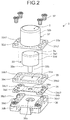
- FIG. 2 is an exploded perspective view of a configuration of the pressure sensor 3 as the first embodiment of the present invention.
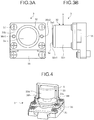
- FIGS. 3A and 3B are a plan view and a side view of the configuration of the pressure sensor 3 as the first embodiment of the present invention.
- the pressure sensor 3 as the first embodiment of the present invention includes a cover member 32, a pressing member 33, a flexure element 34, a flexure element retainer 35, and a support member 36.
- the cover member 32 which may be configured in a mountable and dismountable manner, includes a plate-shaped base 32a having a through hole (not illustrated) at its central position and a cylindrical protection part 32b erected on the base 32a in such a manner as to surround the through hole of the base 32a.
- the protection part 32b covers the peripheral face of the pressing member 33 with the sensor face 3a of the pressing member 33 exposed out of an upper end face 32b1, thereby protecting the pressing member 33 from a lateral force (side pressure) A.
- the cover member 32 functions as a first cover member according to the present invention.
- a perimeter 3a1 of the exposed sensor face 3a is chamfered, whereby a face directed from the rim of the sensor face 3a toward the cover member 32 forms an acute angle relative to a face substantially parallel to the sensor face 3a.
- the side pressure is not applied to the sensor face 3a.
- a clearance is provided between the outer peripheral face of the pressing member 33 and the inner peripheral face of the protection part 32b. The clearance is designed to have a size that can prevent the breakage of the flexure element 34 through contact between the outer peripheral face of the pressing member 33 and the inner peripheral face of the protection part 32b before the flexure element 34 (more specifically, a strain gauge 34b) fixed to the pressing member 33 is broken when the side pressure is applied to the pressing member 33.
- the pressing member 33 includes a cylindrical fixing part 33b and a bottomed cylindrical sensor member 33d fixedly supported by the fixing part 33b.
- the pressing member 33 is mounted on the flexure element 34 by inserting the fixing part 33b into a through hole 34a formed at the central part of the flexure element 34.
- the pressing member 33 and the flexure element 34 may be fixed to each other by crimping, with a screw, or the like.
- a load is applied to the sensor face 3a as the bottom face of the sensor member 33d.
- the sensor member 33d moves in the inside direction of the pressure sensor 3, whereas when no load is being applied to the sensor face 3a, the sensor member 33d returns to its original position through the elastic force of the flexure element 34.
- the flexure element 34 is formed of a metallic material such as a stainless steel plate.
- the through hole 34a into which the fixing part 33b of the pressing member 33 is inserted is formed at the central part of the flexure element 34.
- the strain gauge 34b is mounted around the through hole 34a. The strain gauge 34b outputs an electric signal corresponding to, when the flexure element 34 becomes deformed owing to the load applied to the pressing member 33 and transmitted to the flexure element 34, the amount of deformation of the flexure element 34.
- the flexure element retainer 35 is formed of a metallic material such as a stainless steel plate. An opening 35a into which the pressing member 33 is inserted is formed in the flexure element retainer 35.
- the support member 36 is a member that fixedly supports the cover member 32, the pressing member 33, the flexure element 34, and the flexure element retainer 35.
- a stopper 36a is formed at the central part of the support member 36. There is a clearance between the stopper 36a and the pressing member 33 in a normal state; when the pressing member 33 is pressed, the fixing part 33b of the pressing member 33 comes into contact with the stopper 36a. With this contact, the breakage of the flexure element 34, and thus the strain gauge 34b (extreme bending of the flexure element 34 or the strain gauge 34b, for example) can be prevented.
- a substrate 36b is provided on the top face of the support member 36.
- the substrate 36b mounts thereon circuit elements such as operational amplifiers, resistance elements, and capacitors.
- the substrate 36b is electrically connected to the strain gauge 34b mounted on the flexure element 34 and outputs the electric signal output from the flexure element 34 to the controller of the pump apparatus 1 illustrated in FIG. 1 .
- bosses 36c1 and 36c2 protruding on the top face of the support member 36 are inserted into through holes 34c1 and 34c2, respectively, formed in the flexure element 34.
- the bosses 36c1 and 36c2 of the support member 36 are inserted into through holes 35b1 and 35b2 formed in the flexure element retainer 35.
- the pressing member 33 is inserted into an internal space S of the cover member 32 and the opening 35a of the flexure element retainer 35, and the fixing part 33b of the pressing member 33 is inserted into the through hole 34a of the flexure element 34.
- the bosses 36c1 and 36c2 of the support member 36 are inserted into through holes 32c1 and 32c2, respectively, formed in the cover member 32.
- screws 37 are inserted into through holes 32d of the cover member 32, through holes 35c of the flexure element retainer 35, and through holes 34d of the flexure element 34 to cause the screws 37 to be screwed with screw holes 36d of the support member 36.
- the through hole 34c1 of the flexure element 34, the through hole 35b1 of the flexure element retainer 35, and the through hole 32c1 of the cover member 32 are circular-shaped, whereas the through hole 34c2 of the flexure element 34, the through hole 35b2 of the flexure element retainer 35, and the through hole 32c2 of the cover member 32 are oblong hole-shaped.
- the pressure sensor 3 as the first embodiment of the present invention includes the sensor member 33d including the sensor face 3a to which pressure is imparted, the support member 36 that supports the sensor member 33d, and the cover member 32 that covers the peripheral face of the sensor member 33d while exposing the sensor face 3a out of one end side.
- the sensor member 33d can be protected from the lateral force (the side pressure) A, and the sensor member 33d can be prevented from being broken by the application of the side pressure to the sensor member 33d.
- the pressure sensor 3 can be easily mounted and dismounted on and from the pump apparatus 1 without breaking the base of the pressure sensor 3.
- FIG. 4 is a perspective view of a configuration of the pressure sensor 3 as the second embodiment of the present invention.
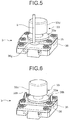
- FIG. 5 is a perspective view of a configuration of a first modification of the pressure sensor as the second embodiment of the present invention.
- FIG. 6 is a perspective view of a configuration of a second modification of the pressure sensor as the second embodiment of the present invention.
- the pressure sensor 3 as the second embodiment of the present invention has a configuration that does not include the cover member 32 in the pressure sensor 3 in the first embodiment.
- the pressing member 33 includes a disc-shaped flange 33a, and when the side pressure is applied, the flange 33a comes into contact with the flexure element retainer 35 to function as a stopper in a side pressure direction.
- jig mounting parts 36f having through holes into which a jig 5 for mounting and dismounting the pressure sensor 3 is inserted is erected on the support member 36.
- the support member 36 includes the jig mounting parts 36f on which the jig 5 can be mounted.
- the jig 5 is for mounting and dismounting the pressure sensor 3 on and from the pump apparatus 1 including the pressure sensor 3.
- the jig 5 is mounted on the jig mounting parts 36f, and the pressure sensor 3 is pulled out via the jig 5.
- a load is applied only to the support member 36 of the pressure sensor 3
- no load is applied to the pressing member 33 and the like
- the pressure sensor 3 can be easily mounted and dismounted on and from the pump apparatus 1 without breaking the base of the pressure sensor 3 similarly to the first embodiment.
- the cover member 32 is configured to be mountable and dismountable, the cover member 32 is mounted, and the pressure sensor 3 is dismounted by directly holding the cover member 32, whereby the pressure sensor 3 can be dismounted without breaking the base thereof.
- the jig 5 may be mounted on the pressure sensor 3 by forming a jig mounting hole 36g in the support member 36 and inserting the jig 5 into the jig mounting hole 36g.
- grips 36h may be erected on the support member 36, and when the pressure sensor 3 in the present embodiment is dismounted from the pump apparatus 1, the pressure sensor 3 may be pulled out by pinching the grips 36h.
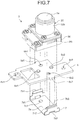
- FIG. 7 is an exploded perspective view of a mounting structure of the pressure sensor 3 as the first and the second embodiments of the present invention.
- FIG. 7 illustrates the pressure sensor as the first embodiment of the present invention as the pressure sensor 3
- this mounting structure can also be used in the pressure sensor as the second embodiment of the present invention as a matter of course.
- the pump apparatus 1 on which the pressure sensor 3 is mounted is provided with a hold plate 6 and a leaf spring 7.
- the hold plate 6 is formed of a plate-shaped metallic member.
- the hold plate 6 includes bosses 6a1 and 6a2 for positioning the pressure sensor 3, bosses 6b1 and 6b2 for positioning the leaf spring 7, through holes 6c1 and 6c2 for fixing the hold plate 6 to the pump apparatus 1, and protrusions 6d1 and 6d2 to be engaged with the leaf spring 7.
- the leaf spring 7 is formed of a metallic member.
- the leaf spring 7 includes a plate-shaped base 7a and spring parts 7b1 and 7b2 erected on both facing side faces of the base 7a.
- Positioning holes 7c1 and 7c2 are formed in the base 7a. Openings 7d1 and 7d2 with which the protrusions 6d1 and 6d2 of the hold plate 6 are engaged are formed in boundaries between the base 7a and the spring parts 7b1 and 7b2.
- the hold plate 6 is arranged from the back side of the pump apparatus 1, and screws are inserted into the through holes 6c1 and 6c2 to be screwed with screw holes of the pump apparatus 1, thereby fixing the hold plate 6 to the pump apparatus 1.
- the positioning holes 7c1 and 7c2 of the leaf spring 7 are fit into the bosses 6b1 and 6b2 of the hold plate 6 to engage the protrusions 6d1 and 6d2 of the hold plate 6 and the openings 7d1 and 7d2 of the leaf spring 7 with each other, thereby fixing the leaf spring 7 to the hold plate 6.
- the pressure sensor 3 is arranged at an arrangement position from the front side of the pump apparatus 1, a connector of the pump apparatus 1 and the pressure sensor 3 are connected to each other, and the spring parts 7b1 and 7b2 are engaged with engagement parts 36i formed in the support member 36 of the pressure sensor 3. Consequently, the pressure sensor 3 can be mounted on the pump apparatus 1.
- the protection part 32b of the cover member 32 is held, and the pressure sensor 3 is pulled out with a force larger than the biasing force of the spring parts 7b1 and 7b2, whereby the pressure sensor 3 can be dismounted from the pump apparatus 1.
- the pressure sensor 3 can be mounted on the pump apparatus 1 with high precision, and clogging of the infusion tube T can be stably detected.
- the pump apparatus 1 supports the pressure sensor 3 in a mountable and dismountable manner using the leaf spring 7 in the present embodiment, the pump apparatus 1 may support the pressure sensor 3 in a mountable and dismountable manner using a support member other than the leaf spring 7.
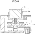
- a gasket 8 that covers the sensor face 3a may be provided as illustrated in FIG. 8 , for example.
- contamination such as an infusion solution adhering to the pump apparatus 1 can be prevented from entering the inside of the pressure sensor 3.
- the gasket 8 functions as a second cover member according to the present invention.
- the sensor face 3a is covered using the gasket 8 in the present embodiments, the sensor face 3a may be covered using a cover member other than the gasket 8.
- the pressure sensor and the apparatus according to the present invention can prevent the base of the pressure sensor from being broken by the application of side pressure to the base of the pressure sensor.
Landscapes
- Physics & Mathematics (AREA)
- General Physics & Mathematics (AREA)
- Chemical & Material Sciences (AREA)
- Analytical Chemistry (AREA)
- Measuring Fluid Pressure (AREA)
- Infusion, Injection, And Reservoir Apparatuses (AREA)
Applications Claiming Priority (2)
| Application Number | Priority Date | Filing Date | Title |
|---|---|---|---|
| JP2016023316A JP2017142149A (ja) | 2016-02-10 | 2016-02-10 | 圧力センサ及び装置 |
| JP2016023317A JP6684604B2 (ja) | 2016-02-10 | 2016-02-10 | 圧力センサを備えた装置 |
Publications (2)
| Publication Number | Publication Date |
|---|---|
| EP3205994A1 true EP3205994A1 (de) | 2017-08-16 |
| EP3205994B1 EP3205994B1 (de) | 2019-03-27 |
Family
ID=58016622
Family Applications (1)
| Application Number | Title | Priority Date | Filing Date |
|---|---|---|---|
| EP17155611.1A Active EP3205994B1 (de) | 2016-02-10 | 2017-02-10 | Drucksensor und vorrichtung |
Country Status (2)
| Country | Link |
|---|---|
| US (1) | US9945748B2 (de) |
| EP (1) | EP3205994B1 (de) |
Cited By (1)
| Publication number | Priority date | Publication date | Assignee | Title |
|---|---|---|---|---|
| DE102018206210A1 (de) * | 2018-04-23 | 2019-10-24 | Continental Automotive Gmbh | Deckelanordnung für einen Sensor sowie Fußgängerschutzsensor für ein Fahrzeug |
Citations (3)
| Publication number | Priority date | Publication date | Assignee | Title |
|---|---|---|---|---|
| US20030104712A1 (en) * | 2001-11-30 | 2003-06-05 | Enplas Corporation | Socket for electrical parts |
| JP2007315792A (ja) | 2006-05-23 | 2007-12-06 | Mitsubishi Electric Corp | 圧力センサの取り付け構造 |
| US20150047439A1 (en) * | 2013-08-19 | 2015-02-19 | Minebea Co., Ltd. | Small-sized load sensor unit |
Family Cites Families (15)
| Publication number | Priority date | Publication date | Assignee | Title |
|---|---|---|---|---|
| EP0381775B1 (de) * | 1988-07-26 | 1994-11-23 | Hitachi Construction Machinery Co., Ltd. | Drucksensor |
| US5406852A (en) * | 1992-03-18 | 1995-04-18 | Matsushita Electric Industrial Co., Ltd. | Pressure sensor having a resistor element on a glass dryer with electrodes connected thereto |
| US5325720A (en) * | 1993-10-07 | 1994-07-05 | The United States Of America As Represented By The Administrator Of The National Aeronautics And Space Administration | Method for making a dynamic pressure sensor and a pressure sensor made according to the method |
| DE102006058301B4 (de) * | 2006-12-11 | 2016-12-29 | Robert Bosch Gmbh | Luftdrucksensor für eine Seitenaufprallerkennung |
| KR100901592B1 (ko) * | 2007-12-13 | 2009-06-08 | 현대자동차주식회사 | 엔진조립라인의 피스톤 핀 위치보정 압입장치 |
| EP2107345A1 (de) * | 2008-03-31 | 2009-10-07 | VEGA Grieshaber KG | Füllstand- und Druckmessgerät mit einem topfförmigen Gehäusedeckel |
| US8397578B2 (en) * | 2010-06-03 | 2013-03-19 | Medtronic, Inc. | Capacitive pressure sensor assembly |
| CN103376174B (zh) * | 2012-04-27 | 2016-03-09 | 鸿富锦精密工业(深圳)有限公司 | 压力检测装置 |
| US9032805B2 (en) * | 2012-05-15 | 2015-05-19 | Fca Us Llc | High pressure visual indicator |
| US8820170B2 (en) * | 2012-09-14 | 2014-09-02 | Sensata Technologies, Inc. | Pressure sensor |
| US9027410B2 (en) * | 2012-09-14 | 2015-05-12 | Sensata Technologies, Inc. | Hermetically glass sealed pressure sensor |
| JP6304989B2 (ja) * | 2013-09-24 | 2018-04-04 | 株式会社東芝 | 圧力センサ、マイクロフォン、血圧センサ、タッチパネル、圧力センサの製造方法、および圧力センサの製造装置 |
| US9625342B2 (en) * | 2014-01-31 | 2017-04-18 | DunAn Sensing, LLC | Sensor housing apparatus providing a hermetic seal |
| US9470595B2 (en) * | 2014-08-29 | 2016-10-18 | Trw Automotive U.S. Llc | Apparatus for dry side mounting a crash pressure sensor |
| US10060813B2 (en) * | 2015-09-29 | 2018-08-28 | Rosemount Inc. | High over-pressure capable silicon die pressure sensor |
-
2017
- 2017-02-07 US US15/426,388 patent/US9945748B2/en active Active
- 2017-02-10 EP EP17155611.1A patent/EP3205994B1/de active Active
Patent Citations (3)
| Publication number | Priority date | Publication date | Assignee | Title |
|---|---|---|---|---|
| US20030104712A1 (en) * | 2001-11-30 | 2003-06-05 | Enplas Corporation | Socket for electrical parts |
| JP2007315792A (ja) | 2006-05-23 | 2007-12-06 | Mitsubishi Electric Corp | 圧力センサの取り付け構造 |
| US20150047439A1 (en) * | 2013-08-19 | 2015-02-19 | Minebea Co., Ltd. | Small-sized load sensor unit |
Cited By (2)
| Publication number | Priority date | Publication date | Assignee | Title |
|---|---|---|---|---|
| US11828886B2 (en) | 2018-03-21 | 2023-11-28 | Continental Automotive Gmbh | Cover assembly for a sensor and pedestrian protection sensor for a vehicle |
| DE102018206210A1 (de) * | 2018-04-23 | 2019-10-24 | Continental Automotive Gmbh | Deckelanordnung für einen Sensor sowie Fußgängerschutzsensor für ein Fahrzeug |
Also Published As
| Publication number | Publication date |
|---|---|
| EP3205994B1 (de) | 2019-03-27 |
| US9945748B2 (en) | 2018-04-17 |
| US20170227413A1 (en) | 2017-08-10 |
Similar Documents
| Publication | Publication Date | Title |
|---|---|---|
| US11820286B2 (en) | Light-emitting device | |
| EP2302434A1 (de) | Antriebsmodul, montageverfahren dafür und elektronische vorrichtung | |
| US20090149055A1 (en) | Connector holding clamp and connector retaining structure | |
| US9497360B2 (en) | Electrode inspection apparatus for spot welding | |
| US9548519B2 (en) | Clamp-on easy-install wireless battery data sensor and associated use thereof | |
| US10185845B2 (en) | Card reader and magnetic information recording medium processing device | |
| US12392645B2 (en) | Magnet fixing implement | |
| EP3205994B1 (de) | Drucksensor und vorrichtung | |
| EP2072983A1 (de) | Formaufspannungskraftmesser | |
| EP0900636A1 (de) | Tragbare handstevereinrichtung | |
| JP2009110815A (ja) | 多光軸光電センサ | |
| CN106990685B (zh) | 图像形成装置 | |
| US11024140B2 (en) | Air monitoring device including a housing with communication port access | |
| EP4266843A1 (de) | Elektronisches gerät mit elektronischer steuervorrichtung | |
| JP6127009B2 (ja) | 物理量測定装置 | |
| JP6684604B2 (ja) | 圧力センサを備えた装置 | |
| EP3188323B1 (de) | Verbindervorrichtung | |
| EP4564544A1 (de) | Entlüftungseinheit zur belüftung eines maschinenraums | |
| CN220098200U (zh) | 电梯控制柜 | |
| JP7568472B2 (ja) | パネルモジュールユニット | |
| JP2017142149A (ja) | 圧力センサ及び装置 | |
| US10421297B2 (en) | Printer | |
| JP2000223165A (ja) | 電源装置 | |
| CN213932942U (zh) | 传感器单元 | |
| US20230291058A1 (en) | Electronic device and battery holder |
Legal Events
| Date | Code | Title | Description |
|---|---|---|---|
| PUAI | Public reference made under article 153(3) epc to a published international application that has entered the european phase |
Free format text: ORIGINAL CODE: 0009012 |
|
| STAA | Information on the status of an ep patent application or granted ep patent |
Free format text: STATUS: REQUEST FOR EXAMINATION WAS MADE |
|
| 17P | Request for examination filed |
Effective date: 20170411 |
|
| AK | Designated contracting states |
Kind code of ref document: A1 Designated state(s): AL AT BE BG CH CY CZ DE DK EE ES FI FR GB GR HR HU IE IS IT LI LT LU LV MC MK MT NL NO PL PT RO RS SE SI SK SM TR |
|
| AX | Request for extension of the european patent |
Extension state: BA ME |
|
| RBV | Designated contracting states (corrected) |
Designated state(s): AL AT BE BG CH CY CZ DE DK EE ES FI FR GB GR HR HU IE IS IT LI LT LU LV MC MK MT NL NO PL PT RO RS SE SI SK SM TR |
|
| STAA | Information on the status of an ep patent application or granted ep patent |
Free format text: STATUS: EXAMINATION IS IN PROGRESS |
|
| 17Q | First examination report despatched |
Effective date: 20180315 |
|
| GRAP | Despatch of communication of intention to grant a patent |
Free format text: ORIGINAL CODE: EPIDOSNIGR1 |
|
| STAA | Information on the status of an ep patent application or granted ep patent |
Free format text: STATUS: GRANT OF PATENT IS INTENDED |
|
| INTG | Intention to grant announced |
Effective date: 20180925 |
|
| GRAS | Grant fee paid |
Free format text: ORIGINAL CODE: EPIDOSNIGR3 |
|
| GRAA | (expected) grant |
Free format text: ORIGINAL CODE: 0009210 |
|
| STAA | Information on the status of an ep patent application or granted ep patent |
Free format text: STATUS: THE PATENT HAS BEEN GRANTED |
|
| AK | Designated contracting states |
Kind code of ref document: B1 Designated state(s): AL AT BE BG CH CY CZ DE DK EE ES FI FR GB GR HR HU IE IS IT LI LT LU LV MC MK MT NL NO PL PT RO RS SE SI SK SM TR |
|
| REG | Reference to a national code |
Ref country code: GB Ref legal event code: FG4D |
|
| REG | Reference to a national code |
Ref country code: CH Ref legal event code: EP |
|
| REG | Reference to a national code |
Ref country code: AT Ref legal event code: REF Ref document number: 1113663 Country of ref document: AT Kind code of ref document: T Effective date: 20190415 |
|
| REG | Reference to a national code |
Ref country code: IE Ref legal event code: FG4D |
|
| REG | Reference to a national code |
Ref country code: DE Ref legal event code: R096 Ref document number: 602017002861 Country of ref document: DE |
|
| PG25 | Lapsed in a contracting state [announced via postgrant information from national office to epo] |
Ref country code: FI Free format text: LAPSE BECAUSE OF FAILURE TO SUBMIT A TRANSLATION OF THE DESCRIPTION OR TO PAY THE FEE WITHIN THE PRESCRIBED TIME-LIMIT Effective date: 20190327 Ref country code: NO Free format text: LAPSE BECAUSE OF FAILURE TO SUBMIT A TRANSLATION OF THE DESCRIPTION OR TO PAY THE FEE WITHIN THE PRESCRIBED TIME-LIMIT Effective date: 20190627 Ref country code: SE Free format text: LAPSE BECAUSE OF FAILURE TO SUBMIT A TRANSLATION OF THE DESCRIPTION OR TO PAY THE FEE WITHIN THE PRESCRIBED TIME-LIMIT Effective date: 20190327 Ref country code: LT Free format text: LAPSE BECAUSE OF FAILURE TO SUBMIT A TRANSLATION OF THE DESCRIPTION OR TO PAY THE FEE WITHIN THE PRESCRIBED TIME-LIMIT Effective date: 20190327 |
|
| REG | Reference to a national code |
Ref country code: NL Ref legal event code: MP Effective date: 20190327 |
|
| PG25 | Lapsed in a contracting state [announced via postgrant information from national office to epo] |
Ref country code: LV Free format text: LAPSE BECAUSE OF FAILURE TO SUBMIT A TRANSLATION OF THE DESCRIPTION OR TO PAY THE FEE WITHIN THE PRESCRIBED TIME-LIMIT Effective date: 20190327 Ref country code: RS Free format text: LAPSE BECAUSE OF FAILURE TO SUBMIT A TRANSLATION OF THE DESCRIPTION OR TO PAY THE FEE WITHIN THE PRESCRIBED TIME-LIMIT Effective date: 20190327 Ref country code: NL Free format text: LAPSE BECAUSE OF FAILURE TO SUBMIT A TRANSLATION OF THE DESCRIPTION OR TO PAY THE FEE WITHIN THE PRESCRIBED TIME-LIMIT Effective date: 20190327 Ref country code: GR Free format text: LAPSE BECAUSE OF FAILURE TO SUBMIT A TRANSLATION OF THE DESCRIPTION OR TO PAY THE FEE WITHIN THE PRESCRIBED TIME-LIMIT Effective date: 20190628 Ref country code: HR Free format text: LAPSE BECAUSE OF FAILURE TO SUBMIT A TRANSLATION OF THE DESCRIPTION OR TO PAY THE FEE WITHIN THE PRESCRIBED TIME-LIMIT Effective date: 20190327 Ref country code: BG Free format text: LAPSE BECAUSE OF FAILURE TO SUBMIT A TRANSLATION OF THE DESCRIPTION OR TO PAY THE FEE WITHIN THE PRESCRIBED TIME-LIMIT Effective date: 20190627 |
|
| REG | Reference to a national code |
Ref country code: AT Ref legal event code: MK05 Ref document number: 1113663 Country of ref document: AT Kind code of ref document: T Effective date: 20190327 |
|
| PG25 | Lapsed in a contracting state [announced via postgrant information from national office to epo] |
Ref country code: EE Free format text: LAPSE BECAUSE OF FAILURE TO SUBMIT A TRANSLATION OF THE DESCRIPTION OR TO PAY THE FEE WITHIN THE PRESCRIBED TIME-LIMIT Effective date: 20190327 Ref country code: ES Free format text: LAPSE BECAUSE OF FAILURE TO SUBMIT A TRANSLATION OF THE DESCRIPTION OR TO PAY THE FEE WITHIN THE PRESCRIBED TIME-LIMIT Effective date: 20190327 Ref country code: RO Free format text: LAPSE BECAUSE OF FAILURE TO SUBMIT A TRANSLATION OF THE DESCRIPTION OR TO PAY THE FEE WITHIN THE PRESCRIBED TIME-LIMIT Effective date: 20190327 Ref country code: CZ Free format text: LAPSE BECAUSE OF FAILURE TO SUBMIT A TRANSLATION OF THE DESCRIPTION OR TO PAY THE FEE WITHIN THE PRESCRIBED TIME-LIMIT Effective date: 20190327 Ref country code: IT Free format text: LAPSE BECAUSE OF FAILURE TO SUBMIT A TRANSLATION OF THE DESCRIPTION OR TO PAY THE FEE WITHIN THE PRESCRIBED TIME-LIMIT Effective date: 20190327 Ref country code: PT Free format text: LAPSE BECAUSE OF FAILURE TO SUBMIT A TRANSLATION OF THE DESCRIPTION OR TO PAY THE FEE WITHIN THE PRESCRIBED TIME-LIMIT Effective date: 20190727 Ref country code: SK Free format text: LAPSE BECAUSE OF FAILURE TO SUBMIT A TRANSLATION OF THE DESCRIPTION OR TO PAY THE FEE WITHIN THE PRESCRIBED TIME-LIMIT Effective date: 20190327 Ref country code: AL Free format text: LAPSE BECAUSE OF FAILURE TO SUBMIT A TRANSLATION OF THE DESCRIPTION OR TO PAY THE FEE WITHIN THE PRESCRIBED TIME-LIMIT Effective date: 20190327 |
|
| PG25 | Lapsed in a contracting state [announced via postgrant information from national office to epo] |
Ref country code: PL Free format text: LAPSE BECAUSE OF FAILURE TO SUBMIT A TRANSLATION OF THE DESCRIPTION OR TO PAY THE FEE WITHIN THE PRESCRIBED TIME-LIMIT Effective date: 20190327 Ref country code: SM Free format text: LAPSE BECAUSE OF FAILURE TO SUBMIT A TRANSLATION OF THE DESCRIPTION OR TO PAY THE FEE WITHIN THE PRESCRIBED TIME-LIMIT Effective date: 20190327 |
|
| PG25 | Lapsed in a contracting state [announced via postgrant information from national office to epo] |
Ref country code: AT Free format text: LAPSE BECAUSE OF FAILURE TO SUBMIT A TRANSLATION OF THE DESCRIPTION OR TO PAY THE FEE WITHIN THE PRESCRIBED TIME-LIMIT Effective date: 20190327 Ref country code: IS Free format text: LAPSE BECAUSE OF FAILURE TO SUBMIT A TRANSLATION OF THE DESCRIPTION OR TO PAY THE FEE WITHIN THE PRESCRIBED TIME-LIMIT Effective date: 20190727 |
|
| REG | Reference to a national code |
Ref country code: DE Ref legal event code: R097 Ref document number: 602017002861 Country of ref document: DE |
|
| PG25 | Lapsed in a contracting state [announced via postgrant information from national office to epo] |
Ref country code: DK Free format text: LAPSE BECAUSE OF FAILURE TO SUBMIT A TRANSLATION OF THE DESCRIPTION OR TO PAY THE FEE WITHIN THE PRESCRIBED TIME-LIMIT Effective date: 20190327 |
|
| PLBE | No opposition filed within time limit |
Free format text: ORIGINAL CODE: 0009261 |
|
| STAA | Information on the status of an ep patent application or granted ep patent |
Free format text: STATUS: NO OPPOSITION FILED WITHIN TIME LIMIT |
|
| PG25 | Lapsed in a contracting state [announced via postgrant information from national office to epo] |
Ref country code: SI Free format text: LAPSE BECAUSE OF FAILURE TO SUBMIT A TRANSLATION OF THE DESCRIPTION OR TO PAY THE FEE WITHIN THE PRESCRIBED TIME-LIMIT Effective date: 20190327 |
|
| 26N | No opposition filed |
Effective date: 20200103 |
|
| PG25 | Lapsed in a contracting state [announced via postgrant information from national office to epo] |
Ref country code: TR Free format text: LAPSE BECAUSE OF FAILURE TO SUBMIT A TRANSLATION OF THE DESCRIPTION OR TO PAY THE FEE WITHIN THE PRESCRIBED TIME-LIMIT Effective date: 20190327 |
|
| REG | Reference to a national code |
Ref country code: CH Ref legal event code: PL |
|
| REG | Reference to a national code |
Ref country code: BE Ref legal event code: MM Effective date: 20200229 |
|
| PG25 | Lapsed in a contracting state [announced via postgrant information from national office to epo] |
Ref country code: MC Free format text: LAPSE BECAUSE OF FAILURE TO SUBMIT A TRANSLATION OF THE DESCRIPTION OR TO PAY THE FEE WITHIN THE PRESCRIBED TIME-LIMIT Effective date: 20190327 Ref country code: LU Free format text: LAPSE BECAUSE OF NON-PAYMENT OF DUE FEES Effective date: 20200210 |
|
| PG25 | Lapsed in a contracting state [announced via postgrant information from national office to epo] |
Ref country code: CH Free format text: LAPSE BECAUSE OF NON-PAYMENT OF DUE FEES Effective date: 20200229 Ref country code: LI Free format text: LAPSE BECAUSE OF NON-PAYMENT OF DUE FEES Effective date: 20200229 |
|
| PG25 | Lapsed in a contracting state [announced via postgrant information from national office to epo] |
Ref country code: IE Free format text: LAPSE BECAUSE OF NON-PAYMENT OF DUE FEES Effective date: 20200210 Ref country code: FR Free format text: LAPSE BECAUSE OF NON-PAYMENT OF DUE FEES Effective date: 20200229 |
|
| PG25 | Lapsed in a contracting state [announced via postgrant information from national office to epo] |
Ref country code: BE Free format text: LAPSE BECAUSE OF NON-PAYMENT OF DUE FEES Effective date: 20200229 |
|
| GBPC | Gb: european patent ceased through non-payment of renewal fee |
Effective date: 20210210 |
|
| PG25 | Lapsed in a contracting state [announced via postgrant information from national office to epo] |
Ref country code: GB Free format text: LAPSE BECAUSE OF NON-PAYMENT OF DUE FEES Effective date: 20210210 |
|
| PG25 | Lapsed in a contracting state [announced via postgrant information from national office to epo] |
Ref country code: MT Free format text: LAPSE BECAUSE OF FAILURE TO SUBMIT A TRANSLATION OF THE DESCRIPTION OR TO PAY THE FEE WITHIN THE PRESCRIBED TIME-LIMIT Effective date: 20190327 Ref country code: CY Free format text: LAPSE BECAUSE OF FAILURE TO SUBMIT A TRANSLATION OF THE DESCRIPTION OR TO PAY THE FEE WITHIN THE PRESCRIBED TIME-LIMIT Effective date: 20190327 |
|
| PG25 | Lapsed in a contracting state [announced via postgrant information from national office to epo] |
Ref country code: MK Free format text: LAPSE BECAUSE OF FAILURE TO SUBMIT A TRANSLATION OF THE DESCRIPTION OR TO PAY THE FEE WITHIN THE PRESCRIBED TIME-LIMIT Effective date: 20190327 |
|
| PGFP | Annual fee paid to national office [announced via postgrant information from national office to epo] |
Ref country code: DE Payment date: 20260218 Year of fee payment: 10 |