EP3206000B1 - Verwendung eines verfahrens zur erzeugung eines lastschätzungsmodells bei einem reifengleichförmigkeitstester - Google Patents
Verwendung eines verfahrens zur erzeugung eines lastschätzungsmodells bei einem reifengleichförmigkeitstester Download PDFInfo
- Publication number
- EP3206000B1 EP3206000B1 EP15848557.3A EP15848557A EP3206000B1 EP 3206000 B1 EP3206000 B1 EP 3206000B1 EP 15848557 A EP15848557 A EP 15848557A EP 3206000 B1 EP3206000 B1 EP 3206000B1
- Authority
- EP
- European Patent Office
- Prior art keywords
- tire
- load
- model
- nominal model
- unit
- Prior art date
- Legal status (The legal status is an assumption and is not a legal conclusion. Google has not performed a legal analysis and makes no representation as to the accuracy of the status listed.)
- Not-in-force
Links
Images





Classifications
-
- G—PHYSICS
- G01—MEASURING; TESTING
- G01M—TESTING STATIC OR DYNAMIC BALANCE OF MACHINES OR STRUCTURES; TESTING OF STRUCTURES OR APPARATUS, NOT OTHERWISE PROVIDED FOR
- G01M17/00—Testing of vehicles
- G01M17/007—Wheeled or endless-tracked vehicles
- G01M17/02—Tyres
- G01M17/022—Tyres the tyre co-operating with rotatable rolls
-
- B—PERFORMING OPERATIONS; TRANSPORTING
- B29—WORKING OF PLASTICS; WORKING OF SUBSTANCES IN A PLASTIC STATE IN GENERAL
- B29D—PRODUCING PARTICULAR ARTICLES FROM PLASTICS OR FROM SUBSTANCES IN A PLASTIC STATE
- B29D30/00—Producing pneumatic or solid tyres or parts thereof
- B29D30/0061—Accessories, details or auxiliary operations not otherwise provided for
-
- B—PERFORMING OPERATIONS; TRANSPORTING
- B29—WORKING OF PLASTICS; WORKING OF SUBSTANCES IN A PLASTIC STATE IN GENERAL
- B29D—PRODUCING PARTICULAR ARTICLES FROM PLASTICS OR FROM SUBSTANCES IN A PLASTIC STATE
- B29D30/00—Producing pneumatic or solid tyres or parts thereof
- B29D30/06—Pneumatic tyres or parts thereof (e.g. produced by casting, moulding, compression moulding, injection moulding, centrifugal casting)
- B29D30/0601—Vulcanising tyres; Vulcanising presses for tyres
- B29D30/0633—After-treatment specially adapted for vulcanising tyres
-
- G—PHYSICS
- G01—MEASURING; TESTING
- G01M—TESTING STATIC OR DYNAMIC BALANCE OF MACHINES OR STRUCTURES; TESTING OF STRUCTURES OR APPARATUS, NOT OTHERWISE PROVIDED FOR
- G01M1/00—Testing static or dynamic balance of machines or structures
- G01M1/14—Determining imbalance
- G01M1/16—Determining imbalance by oscillating or rotating the body to be tested
-
- G—PHYSICS
- G01—MEASURING; TESTING
- G01M—TESTING STATIC OR DYNAMIC BALANCE OF MACHINES OR STRUCTURES; TESTING OF STRUCTURES OR APPARATUS, NOT OTHERWISE PROVIDED FOR
- G01M1/00—Testing static or dynamic balance of machines or structures
- G01M1/14—Determining imbalance
- G01M1/16—Determining imbalance by oscillating or rotating the body to be tested
- G01M1/28—Determining imbalance by oscillating or rotating the body to be tested with special adaptations for determining imbalance of the body in situ, e.g. of vehicle wheels
-
- G—PHYSICS
- G01—MEASURING; TESTING
- G01M—TESTING STATIC OR DYNAMIC BALANCE OF MACHINES OR STRUCTURES; TESTING OF STRUCTURES OR APPARATUS, NOT OTHERWISE PROVIDED FOR
- G01M17/00—Testing of vehicles
- G01M17/007—Wheeled or endless-tracked vehicles
- G01M17/02—Tyres
-
- B—PERFORMING OPERATIONS; TRANSPORTING
- B29—WORKING OF PLASTICS; WORKING OF SUBSTANCES IN A PLASTIC STATE IN GENERAL
- B29D—PRODUCING PARTICULAR ARTICLES FROM PLASTICS OR FROM SUBSTANCES IN A PLASTIC STATE
- B29D30/00—Producing pneumatic or solid tyres or parts thereof
- B29D30/0061—Accessories, details or auxiliary operations not otherwise provided for
- B29D2030/0066—Tyre quality control during manufacturing
-
- B—PERFORMING OPERATIONS; TRANSPORTING
- B29—WORKING OF PLASTICS; WORKING OF SUBSTANCES IN A PLASTIC STATE IN GENERAL
- B29D—PRODUCING PARTICULAR ARTICLES FROM PLASTICS OR FROM SUBSTANCES IN A PLASTIC STATE
- B29D30/00—Producing pneumatic or solid tyres or parts thereof
- B29D30/06—Pneumatic tyres or parts thereof (e.g. produced by casting, moulding, compression moulding, injection moulding, centrifugal casting)
- B29D30/0601—Vulcanising tyres; Vulcanising presses for tyres
- B29D30/0633—After-treatment specially adapted for vulcanising tyres
- B29D2030/0634—Measuring, calculating, correcting tyre uniformity, e.g. correcting RFV
-
- B—PERFORMING OPERATIONS; TRANSPORTING
- B29—WORKING OF PLASTICS; WORKING OF SUBSTANCES IN A PLASTIC STATE IN GENERAL
- B29D—PRODUCING PARTICULAR ARTICLES FROM PLASTICS OR FROM SUBSTANCES IN A PLASTIC STATE
- B29D30/00—Producing pneumatic or solid tyres or parts thereof
- B29D30/06—Pneumatic tyres or parts thereof (e.g. produced by casting, moulding, compression moulding, injection moulding, centrifugal casting)
- B29D30/0601—Vulcanising tyres; Vulcanising presses for tyres
- B29D30/0633—After-treatment specially adapted for vulcanising tyres
- B29D2030/0634—Measuring, calculating, correcting tyre uniformity, e.g. correcting RFV
- B29D2030/0635—Measuring and calculating tyre uniformity, e.g. using mathematical methods
Definitions
- the present invention relates to a use of a method for generating a load estimation model which expresses a relation between a pressing position of a rotary drum against a tire and a tire load generated in the tire in a tire uniformity testing apparatus.
- the tire flowing from the upstream of an inspection line is sandwiched by divided upper and lower rims, and the tire is inflated in a short time and fixed between the upper and lower rims.
- the rotary drum is pressed against the tire held at the test pressure and is rotated normally or reversely to measure the tire uniformity.
- the tire testing apparatus is controlled using the relation existing between the pressing position of the rotary drum and the generated tire load to measure the tire uniformity.
- document JP 2013 - 124858 A a tire testing apparatus is controlled, using a spring constant when assuming that a pressing position of a rotary drum and a tire load generated at the pressing position linearly change. That is, document JP 2013 - 124858 A discloses a method for measuring the relation between the pressing position and the generated tire load in advance, calculating the spring constant from the measured value, and controlling the tire load (pressing load) assuming that the calculated spring constant is constant.
- Document JP 2001 194271 A discloses a method for measuring the uniformity of a high-throughput tire. Until the deviation between the average load value of a tire for every one rotation and a predetermined set load value lies within a predetermined measurable range, the location of an load wheel is controlled through the use of spring constant of a tire determined by the following order of priority 1, 2, and 3. Load wheel location control is performed on the tire though the use of a computed tire spring constant Kc1 of the value obtained by dividing the amount of load change by a previous-time load wheel location control value (field- proven value) in the order of priority 1.
- Load wheel location control is performed on the tire through the use of a computed tire spring constant Kc2 of the same size as a tire measured in a previous time in the case the sizes of the tires are same in the order of priority 2.
- Load wheel location control is performed on the tire through the use of a temporary tire spring constant Kt in the case that the size of a tire is one for the first time in the order of priority 3.
- Document JP 2006 105775 A discloses a tire uniformity measuring method capable of excluding RFV components caused by a rim for mounting a tire and a loading drum to which the tire is pressed and identifying RFV of the tire without having to sacrifice the efficiency of uniformity measurements, and a corresponding measuring apparatus.
- an RFV waveform (X) caused only by the tire is determined by subtracting both an RFV error component (rim component waveform) caused by the rim and an RFV error component (drum component waveform) caused by the loading drum from an RFV waveform (F) acquired by rotating the tire once or more.
- the amplitude of the determined tire component waveform is identified as RFV of the tire.
- the rim component waveform to be identified is acquired by multiplying a rim radium variation waveform indicating changes in the radius of the tire mounted to a circumferential angular position of the rim, which is previously identified to the rim, by a tire vertical spring constant indicating the radial rigidity of the tire previously measured on a tire of the same type of tire as that of the tire to be measured.
- the pressing load setting method disclosed in document JP 2013 - 124858 A is configured to calculate the tire load from the pressing position of the rotary drum against the tire on the assumption that the spring constant is constant.
- a tire load under measurement is acquired based on the spring constant calculated from the displacement of the pressing position measured until the target pressing load is attained and the change amount of the feedback value of the pressing load to control the pressing position of the tire.
- the spring constant (referred to as a true spring constant) of the tire under measurement tends to fluctuate under the influence of the disturbance component
- the spring constant acquired by the calculation does not necessarily coincide with the true spring constant, and there is a possibility of including an error with respect to the true spring constant. Therefore, according to the method disclosed in document JP 2013 - 124858 A , since an inaccurate spring constant including such an error is used, it is difficult to accurately add the tire load necessary for measuring the tire uniformity to the tire.
- the present invention has been made in view of the above-mentioned problems, and an object of the present invention is to provide a use of a method for generating a load model in a tire uniformity testing apparatus capable of generating a load model in which a tire load necessary for measuring the tire uniformity can be acquired accurately and in a short time.
- Fig. 1 is a plan view illustrating a schematic configuration of the tire uniformity testing apparatus 1.
- Fig. 2 is a front view illustrating a schematic configuration of the tire uniformity testing apparatus.
- the tire uniformity testing apparatus 1 evaluates the tire uniformity (or simply, uniformity), which is homogeneity or uniformity of the product tire 8, for example, radial force variation (RFV) generated in the tire 8, as a product inspection.
- uniformity or simply, uniformity
- the tire uniformity testing apparatus 1 (hereinafter referred to as the tire testing apparatus 1) includes a rotary drum 2 which is a cylindrical rotating body provided so that an axis thereof faces upward and downward, and a tire shaft 3 which is a shaft provided to be parallel to the axis of the rotary drum 2 and is freely rotatable around its own axis.
- the rotary drum 2 has a cylindrical drum member 4 having a tire testing simulated road surface formed on its outer peripheral surface, a rotary shaft 5 which rotatably supports the cylindrical drum member 4 at the axial center position, and a frame member 6 which supports the rotary shaft 5.
- the drum member 4 has a shape in which a dimension in a vertical direction (a direction perpendicular to a radial direction) is shorter than a length in a radial direction (e.g., a diameter), and when the length along the axial direction of the cylindrical member is defined as a measure, the drum member 4 is formed into a short cylindrical shape with a large diameter.
- a rotary shaft 5 that rotatably supports the drum member 4 is provided.
- the frame member 6 has a pair of upper and lower support frames provided so as to protrude in the horizontal direction along the radial direction of the drum member 4, and the rotary shaft 5 can be supported between the pair of upper and lower support frames so as to bridge the vertical direction.
- a load measuring unit (not illustrated) is provided between the rotary shaft 5 and the frame member 6, to be capable of measuring a load or a moment generated on the rotary shaft 5 when the rotary drum 2 is pressed against the tire 8.
- the frame member 6 supports the rotary shaft 5 via the load measuring unit.
- the load measuring unit according to the present example is attached to the rotary shaft 5 side of the rotary drum 2, but the load measuring unit can also be attached to the side of the tire shaft 3 described later to measure the load generated on the tire shaft 3.
- drum moving unit 7 capable of horizontally moving the rotary drum 2 with respect to a foundation on which the tire testing apparatus 1 is installed.
- the rotary drum 2 can approach and separate from the tire shaft 3.
- the rotary drum 2 is pressed against the tire 8 held at the test pressure.
- the rotary drum 2 is pressed against the tire 8 by adjusting the position of the rotary drum 2 with respect to the tire 8. As the rotary drum 2 comes closer to the tire 8, the rotary drum 2 is strongly pressed against the tire 8. At this time, the load applied (generated) to the tire 8 by the pressing of the rotary drum 2 is referred to as a pressing load.
- the position (pressing position) with respect to the tire 8 is adjusted so that a target pressing load (target pressing load) is applied to the tire 8.
- a target pressing load target pressing load
- the pressing load applied to the tire 8 correspond one-to-one to the pressing position of the rotary drum 2 which achieves the pressing load. Therefore, for a target pressing load, one objective pressing position (target pressing position) is determined.
- the tire shaft 3 is a bar-like member provided along the vertical direction.
- rotation unit (not illustrated) for rotating the tire shaft 3 about the axis of the tire shaft 3 facing in the vertical direction is provided.
- a rim member (not illustrated) capable of fixing the tire 8 as the measurement object of the tire uniformity is provided.
- the tire 8 can be fixed to the tire shaft 3 via the rim member.
- the above-described tire uniformity is measured on the premise that the rotary drum 2 is accurately pressed against the tire 8 with the target pressing load. Therefore, it is extremely important to accurately apply the target pressing load to the tire 8 during the tire uniformity test for accurately measuring the tire uniformity.
- the tire testing apparatus 1 is provided with a control device 100 for controlling the pressing position of the rotary drum 2 in order to accurately achieve the target pressing load.
- Fig. 3 is a block diagram illustrating a configuration of a control device 100 connected to the tire testing apparatus 1 according to the present example to generate a load model.
- the control device 100 includes an operation DB 110 serving as a database which stores information on the tire 8 acquired as a result of the operation of the tire testing apparatus 1 as operation data, a successive estimation model unit 120 which estimates a pressing load to be applied to the tire 8, using a load estimation model to be described later and information of the tire 8 stored in the operation DB 110, and a load estimation model (nominal model) generating unit 130 which generates a load estimation model as a nominal model of the load model used in the successive estimation model unit 120.
- an operation DB 110 serving as a database which stores information on the tire 8 acquired as a result of the operation of the tire testing apparatus 1 as operation data
- a successive estimation model unit 120 which estimates a pressing load to be applied to the tire 8, using a load estimation model to be described later and information of the tire 8 stored in the operation DB 110
- a load estimation model (nominal model) generating unit 130 which generates a load estimation model as a nominal model of the load model used in the successive estimation model unit 120.
- the operation data stored in the operation DB 110 is information on the tire 8 which is attached to the tire testing apparatus 1 and on which the tire uniformity is measured (or has been measured), and is output from the tire testing apparatus 1.
- the operation data includes information indicating the type (characteristic value) of the tire 8 and information acquired during measurement of the tire uniformity.
- the information indicating the type which is the characteristic value of the tire 8 there are parameters such as the brand and usage of the tire 8, the tire diameter and the tire width (hereinafter referred to as tire parameters).
- the information acquired during the measurement of the tire uniformity includes a pressing position, a pressing load at the pressing position (a pressing load measured by the load measuring unit of the rotary drum 2) and the like.
- the load estimation model generating unit 130 which is a characteristic configuration of the control device 100, will be described.
- the load estimation model generating unit 130 includes a nominal model DB 131, a model selection unit 132, and a nominal model unit 133.
- the nominal model DB 131 is a database that stores information for generating a load estimation model, which is a nominal model, as nominal model data for each type of the tire 8.
- the model selection unit 132 switches and selects the nominal model data stored in the nominal model DB 131, depending on the type of the tire 8 in which the tire uniformity is measured by the tire testing apparatus 1.
- a load estimation model which is a nominal model is generated, using the nominal model data selected by the model selection unit 132.
- the nominal model DB 131 is a database that stores and accumulates the past operating results of the tire testing apparatus 1 as nominal model data for each type of the tire 8.
- the nominal model DB 131 stores and accumulates operation data (pressing position, pressing load at the pressing position, etc.) acquired during the measurement of the tire uniformity and stored in the operation DB 110 for each type of the tire 8.
- the tires 8 having the same tire parameters can be divided (classified) as the same type.
- the tire 8 having the same combination of the tire parameter value and the brand and usage of the tire 8 may be recognized as the same type.
- the nominal model DB 131 stores databases of tires A to X as types of the tire 8.
- the tires A to X may be classified based only on the tire diameter, or may be classified based only on the tire width. Further, the tires A to X may be classified based on a combination of the tire diameter and the tire width, and the tires may be classified based on the combination of the tire diameter, the tire width and the brand. In the present example, it is assumed that the types (tires A to X) of the tire 8 are classified based on a combination of the tire diameter and the tire width.
- the model selection unit 132 acquires information indicating the type of the tire 8 among the information stored in the operation DB 110 from the operation DB 110 to specify the type of the tire 8, and also selects the nominal model data of the type corresponding to the type of the specified tire 8. For example, the model selection unit 132 acquires the tire diameter and the tire width of the tire 8 from the operation DB 110, and selects the nominal model data of types (tires A to X) corresponding to the combination of the acquired tire diameter and the tire width, and outputs the nominal model data to the nominal model unit 133 to be described later.
- the nominal model unit 133 acquires the nominal model data output from the model selection unit 132, and generates a load estimation model for the tire 8 as a nominal model based on the acquired nominal model data.
- a load estimation formula is exemplified as a load estimation model.
- the nominal model data acquired from the model selection unit 132 includes operation data (for example, pressing position or pressing load at the pressing position) acquired during measurement of tire uniformity.
- the nominal model unit 133 generates a distribution of the pressing load with respect to the pressing position, using this operation data, and acquires the coefficient parameters a ij and a 0j of the regression formula illustrated in the following formula (1) in the generated distribution.
- the formula (1) in which the coefficient parameters a ij and a 0j are determined based on the nominal model data is the nominal model.
- the pressing load (corresponding to left side of formula (1)) generated in the tire 8 by the pressing position (corresponding to the variable x in the formula (1)) of the rotary drum 2 can be estimated as the load estimation value.
- a pressing position of the rotary drum 2 corresponding to the target pressing load is calculated as a target pressing position, and the calculated target pressing position is output to a successive estimation model unit 120 to be described later.
- the successive estimation model unit 120 acquires the target pressing position output by the nominal model unit 133 of the load estimation model generating unit 130. Then, the successive estimation model unit 120 instructs the rotary drum 2 to be pressed against the tire 8 at the acquired target pressing position. Thereafter, the successive estimation model unit 120 acquires the pressing position and the pressing load measured by the load measuring unit of the rotary drum 2 from the operation data that is output from the tire testing apparatus 1 and stored in the operation DB 110, and sequentially calculates the pressing position of the rotary drum 2 so that the acquired pressing load becomes the target pressing load, and outputs the pressing position to the tire testing apparatus 1.
- the load estimation model generating unit 130 uses the nominal model to calculate the pressing position (target pressing position) that achieves the target pressing load in the tire 8, and provides the calculated target pressing position to the successive estimation model unit 120.
- the successive estimation model unit 120 can start the sequential calculation of the pressing position from the pressing position at which the target pressing load can be achieved with a high probability.
- the tire testing apparatus 1 can apply the target pressing load to the tire 8 in a very short time from the start of the measurement of the tire uniformity of the tire 8. In this way, if the target pressing load can be applied to the tire 8 in a short time, the start of measuring the tire uniformity can be shortened, and it is possible to improve the operation efficiency and the productivity of the tire testing apparatus 1.
- the successive estimation model unit 120 sequentially measures the tire load, while changing the pressing position of the rotary drum 2 with respect to the tire T.
- the successive estimation model unit 120 weights the measured value of the successively measured tire load to increase the weight as the measured value approaches the target value of the tire load, and estimates the load model representing the relation between the pressing position and the pressing load, using the spring constant, based on the weighted measured value.
- the load model is estimated, by adopting a linear formula in which the pressing position of the rotary drum 2 and the pressing load applied to the tire 8 linearly change, and by fitting a linear formula with respect to the weighted measured value to acquire the spring constant from the slope of the linear formula after fitting.
- the load model adopted by the successive estimation model unit 120 does not consider that linearity is established for all data at the pressing position over a wide range, but mainly considers linearity at some pressing positions that achieves a value in the vicinity of the target pressing load on the tire 8.
- the successive estimation model unit 120 can also accurately achieve the pressing load to be applied to the tire 8, by preferentially using the measured value in the vicinity of the "target pressing load” such that a linear relation with the tire load is established.
- the successive estimation model unit 120 processes the measured value of the pressing load measured by the above-described load measuring means with a predetermined weighting characteristic function to perform "weighting”, and acquires (acquires the above-mentioned linear formula) the spring constant, by preferentially using the measurement data in a range such that a linear relation is established between the pressing position of the rotary drum 2 and the pressing load applied to the tire 8.
- the weighting characteristic function is a function in which the maximum weight W max is acquired when the tire load measured by the load measuring unit is the "target pressing load", and "weighting" abruptly decreases and becomes zero when the tire load deviates from the "target pressing load”. Therefore, if the measured value of the pressing load measured by the load measuring unit is processed with the above-mentioned weighting characteristic function, it is possible to acquire a linear formula preferentially using the measured value located in the vicinity of the "target pressing load".
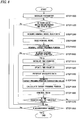
- Fig. 4 is a flowchart illustrating a processing procedure of the method for generating the load model according to the present example.
- the control device 100 acquires the type of the tire 8 as the measurement object of the tire uniformity from the tire testing apparatus 1, and stores the type in the operation DB 110.
- the model selection unit 132 acquires the tire diameter and the tire width of the tire 8 from the operation DB 110 as the type of the tire 8, and searches the nominal model data of the type (tire A to tire X) corresponding to the acquired combination of the tire diameter and the tire width (STEP 1100).
- the information acquired in the measurement is held as nominal model data for each type (characteristic value) of the tire (holding step).
- the model selection unit 132 outputs the nominal model data to the nominal model unit 133.
- the nominal model unit 133 acquires the output nominal model data as data for generating (building) a nominal model.
- the model selection unit 132 acquires a nominal model used for generating the load estimation model (load estimation formula) from the information (nominal model data) held in the holding step, depending on the type (characteristic value) of the tire 8 (an acquiring step, STEP 1200).
- the nominal model unit 133 acquires the coefficient parameters aij and aoj of the regression formula illustrated in the above formula (1) based on the nominal model data acquired from the model selection unit 132, and generates (builds) the nominal model (load estimation formula). That is, based on the acquired nominal model data, a load estimation formula expressing the relation between the pressing position on the tire 8 and the pressing load applied to the tire 8 is generated as a nominal model (generating step, STEP 1300).
- the nominal model unit 133 calculates the pressing position of the rotary drum 2 corresponding to the target pressing load of the tire 8, as the target pressing position (nominal target pressing position) provided by the nominal model, using the built nominal model, and outputs the pressing position acquired by this calculation to the successive estimation model unit 120 (STEP 1400).
- the successive estimation model unit 120 acquires the pressing position that is output from the nominal model unit 133 of the load estimation model generating unit 130, and starts the controlling of the pressing position of the rotary drum 2 from the acquired pressing position (STEP 1500).
- the data of the pressing load and the measured value (the pressing load and the pressing position) of the pressing position of the rotary drum 2 are output to the operation DB 110 of the control device 100, and are stored in the operation DB 110 as measured values for the tire 8.
- the data of the measured value (pressing load and pressing position) stored in the operation DB 110 are output to the successive estimation model unit 120.
- the successive estimation model unit 120 appropriately performs "initialization of the time counter", “update of the time counter”, “preservation of the measurement data” and the like as needed (STEPs 1510 to 1530).
- the successive estimation model unit 120 performs the above-described weighting on the measured value of the pressing load, based on the pressing position of the rotary drum 2 that is output from the operation DB 110.
- the weighting function stored in the control device in advance is applied to the pressing load that is the measured value which is output from the operation DB 110. Weighting based on whether or not the pressing position of the rotary drum 2 is located in the vicinity of the "target pressing load” is applied to the pressing load, by this weighting function. When the pressing position is a value close to the "target pressing load”, large weighting is given, and when the pressing position is a value far from the "target pressing load”, weighting close to zero is given.
- the successive estimation model unit 120 estimates the load model, using the measured value (pressing load) of the tire load weighted in this way. Based on the estimated load model, the successive estimation model unit 120 estimates a correction value (target pressing position correction value) for the pressing position that is output from the nominal model unit 133 in STEP 1400 (STEP 1540).
- the successive estimation model unit 120 calculates a "spring constant” as the proportional constant and estimates the load model, on the assumption that linearity is established between the measured value of the weighted pressing load and the pressing position of the rotary drum 2.
- the "spring constant” calculated in this way is calculated using mainly the measured value in the vicinity of the "target pressing load", and can accurately estimate the pressing load by this estimated load model.
- the successive estimation model unit 120 adds the correction value (target pressing position correction value) estimated in STEP 1540 to the pressing position that is output from the nominal model unit 133 in STEP 1400, and corrects (calculates) the target pressing position of the rotary drum 2 (STEP 1550).
- the target pressing position of the rotary drum 2 calculated and corrected by the successive estimation model unit 120 is output to the tire testing apparatus 1.
- the tire testing apparatus 1 controls the pressing position of the rotary drum 2 in accordance with the output target pressing position (STEP 1560).
- the successive estimation model unit 120 repeats the aforementioned series of processes of STEP 1500 to STEP 1560 until the time counter reaches a predetermined time (STEP 1570).
- a method for generating a "load estimation model" used in the tire uniformity testing apparatus 1 exemplified in Figs. 1 and 2 will be described.
- a configuration of a control device 200 illustrated in Fig. 5 will be described.
- control device 200 even when the nominal model data corresponding to the type of the tire 8 whose tire uniformity is measured by the tire testing apparatus 1 is not stored in the nominal model DB 131, it is possible to generate the "load estimation model" explained in the example useful for understanding the invention.
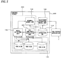
- Fig. 5 is a block diagram illustrating the configuration of the control device 200 connected to the tire testing apparatus 1 according to the present embodiment to generate a load model.
- the control device 200 is provided in the tire testing apparatus 1 to accurately achieve the target pressing load, and controls the pressing position of the rotary drum 2.
- the control device 200 includes an operation DB 110, a successive estimation model unit 120, and a load estimation model generating unit 230.
- the operation DB 110 and the successive estimation model unit 120 have the same configurations as those of the operation DB 110 and the successive estimation model unit 120 described in the example useful for understanding the invention.
- the load estimation model generating unit 230 includes a nominal model DB 131, a model selection unit 132, a nominal model unit 133, and a tire similarity calculation unit 231.
- the nominal model DB 131, the model selection unit 132 and the nominal model unit 133 have the same configurations as those of the nominal model DB 131, the model selection unit 132 and the nominal model unit 133 described in the example useful for understanding the invention.
- control device 200 is characterized by including the tire similarity calculation unit 231. Therefore, the configuration of the tire similarity calculation unit 231 will be described below.
- the tire similarity calculation unit 231 acquires information indicating the type of the tire 8 among the information stored in the operation DB 110 from the operation DB 110, and specifies the type of the tire 8 as the measurement object. Along with this, the tire similarity calculation unit 231 searches the type of nominal model data corresponding to the identified type of the tire 8 in the nominal model DB 131, and when the target nominal model data does not exist, the tire similarity calculation unit 231 acquires the type with the highest similarity to the type of the tire 8. Specifically, the tire similarity calculation unit 231 calculates and acquires type with the highest similarity to the type (characteristic value) of the tire 8 as the measurement object, among the types (characteristic values) of the tire in which the nominal model data is stored in the nominal model DB 131.
- the tire similarity calculation unit 231 calculates the distance in the parameter space between the type (characteristic value) of the tire 8 as the measurement object and all the types (characteristic values) of the tires stored in the nominal model DB 131 by the above formula (2).
- the standardized value for the tire type n of the tire 8 as the measurement object in the formula (2) is acquired by the following formula (3), and the standardized value for the tire type j in the nominal model DB 131 is acquired by the following formula (4).
- y nk ⁇ y nk ⁇ ⁇ k ⁇ k
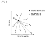
- Fig. 6 is an explanatory view schematically illustrating the distance from the type of the tire of the nominal model DB in the parameter space, with respect to the type of the tire 8 as the measurement object.
- Fig. 6 in the parameter space based on the tire diameter (outer diameter) and tire width which are two tire parameters, the position of the tire 8 (measured tire) as the measurement object, and the positions of the ten tires (tires A to J) of the nominal model data are illustrated.
- the tire similarity calculation unit 231 calculates the distance from the tire 8 to the tires A to J, using the above formula (2), determines and acquires the type of tire of the nominal model data at the shortest distance from the tire 8 among the distances acquired by this calculation, based on the following formula (7).
- dID n arg min j ⁇ J d nj
- Fig. 6 illustrates that the nominal model data located at the shortest distance from the tire 8 is the data of the tire B.
- the tire similarity calculation unit 231 determines that the type of the tire B at the shortest distance has the highest similarity to the type of the tire 8, and outputs the result of this determination to the model selection unit 132.
- Fig. 7 is a flowchart that illustrates a processing procedure of a method for generating the load model according to the present embodiment.
- the same process as the flowchart of Fig. 4 described in the example useful for understanding the invention is denoted by the same step (STEP) number.
- STEP 1000 and STEP 1200 to STEP 1600 are the same processes as in the example useful for understanding the invention, and in the present embodiment, processes in STEP 2000 to STEP 2200 performed by the tire similarity calculation unit 231 are characterized. Therefore, in the following description, only the processes of STEP 2000 to STEP 2200 will be described.
- the tire similarity calculation unit 231 calculates the distance on the parameter space of the type (characteristic value) of the tire 8 as the measurement object and the all types (characteristic values) of the tire stored in the nominal model DB 131, using the above-described formula (2) (STEP 2000).
- the tire similarity calculation unit 231 determines and acquires the type of tire of the nominal model data at the shortest distance from the tire 8 using formula (7) (STEP 2100).
- the tire similarity calculation unit 231 determines whether or not the type of the tire of the nominal model data at the shortest distance is equal to or less than a predetermined distance from the type of the tire 8 as the measurement object. That is, the tire similarity calculation unit 231 determines whether or not the distance from the type of the tire 8 as the measurement object to the type of the tire at the shortest distance is equal to or less than the threshold value, and if the distance is equal to or less than the threshold value, the tire similarity calculation unit 231 outputs the type of a certain tire at the shortest distance to the model selection unit 132 (STEP 2200).
- the model selection unit 132 acquires the type of tire that is located at the shortest distance output from the tire similarity calculation unit 231.
- the model selection unit 132 outputs the nominal model data of the acquired tire type to the nominal model unit 133.
- the nominal model unit 133 acquires the output nominal model data as data for generating (building) a nominal model. That is, by using the information held in the holding step, the nominal model data used for generating the nominal model which is the load estimation formula (load estimation model) is acquired depending on the tire characteristic value of another tire having the highest similarity with respect to the tire 8 (acquiring step, STEP 1200).
- the control of the pressing position of the rotary drum 2 can be started from a pressing position at which the target pressing load is substantially achieved. This makes it possible to precisely control the position of the rotary drum 2 using a plurality of measurement data and accurately measure the tire uniformity of the tire 8 in a short time.
- a method for generating a "load estimation model" used in the tire uniformity testing apparatus 1 exemplified in Figs. 1 and 2 will be described.
- a configuration of a control device 300 illustrated in Fig. 8 will be described.
- control device 300 even when the nominal model data corresponding to the type of the tire 8 in which the tire uniformity is measured by the tire testing apparatus 1 is not stored in the nominal model DB 131, it is possible to generate the "load estimation model" explained in the example useful for understanding the invention.
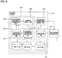
- Fig. 8 is a block diagram illustrating the configuration of the control device 300 connected to the tire testing apparatus 1 according to this embodiment to generate a load model.
- the control device 300 is provided in the tire testing apparatus 1 in order to accurately achieve the target pressing load, and controls the pressing position of the rotary drum 2.
- the control device 300 includes an operation DB 110, a successive estimation model unit 120, and a load estimation model generating unit 330.
- the operation DB 110 and the successive estimation model unit 120 have the same configuration as those of the operation DB 110 and the successive estimation model unit 120 described in the example useful for understanding the invention.
- the load estimation model generating unit 330 includes a nominal model DB 131, a coefficient parameter calculation unit 332, a coefficient parameter database (DB) 333, a coefficient parameter estimation unit 334, and a nominal model unit 335.
- the nominal model DB 131 has the same configuration as that of the nominal model DB 131 described in the example useful for understanding the invention.
- the coefficient parameter calculation unit 332, the coefficient parameter database (DB) 333, the coefficient parameter estimation unit 334, and the nominal model unit 335, which are characteristic configurations of the control device 300, will be described below.
- the coefficient parameter calculation unit 332, the coefficient parameter database (DB) 333, the coefficient parameter estimation unit 334, and the nominal model unit 335, which will be described below, obtain the following formula (8) to be described later as a load estimation formula that is a load estimation model (nominal model).
- the nominal model represented by this formula (8) is finally acquired by the nominal model unit 335, but the nominal model unit 335 generates the nominal model, using the coefficient parameter estimation value which is obtained by the following formula (9) in the coefficient parameter estimation unit 334.
- the coefficient parameter calculation unit 332 to be described next acquires a multiple regression coefficient vector used as a coefficient in formula (9) for acquiring the coefficient parameter estimated value.
- the coefficient parameter calculation unit 332 acquires the multiple regression coefficient vector bi according to the following formulas (10) and (11) for each nominal model data stored in the nominal model DB 131, using the nominal model data.
- the multiple regression coefficient vector bi is acquired for each nominal model data and for each type of tire parameter (that is, tire diameter and tire width).
- the coefficient parameter calculation unit 332 determines the coefficient parameter estimation formula illustrated in the formula (9), using the multiple regression coefficient vector bi according to the formulas (10) and (11), and calculates the coefficient parameter corresponding to the tire parameter as the characteristic values of the tire 8 or the nominal model data.
- the coefficient parameter corresponding to the tire diameter is calculated as the characteristic value of the nominal model data, for each nominal model data.
- the coefficient parameter corresponding to the tire width is calculated as the characteristic value of the nominal model data for each nominal model data.
- the coefficient parameter DB 333 stores the coefficient parameters acquired by the coefficient parameter calculation unit 332 for each nominal model data.
- the coefficient parameter estimation unit 334 estimates the coefficient parameter for the tire 8 as the measurement object, and outputs the estimated coefficient parameter to the nominal model unit 335.
- Fig. 9 is an explanatory view illustrating a method for estimating coefficient parameters according to the present embodiment.
- Each of a plurality of black circles " ⁇ "illustrated in Fig. 9 represents a coefficient parameter acquired from the coefficient parameter DB 333, and the distribution of the coefficient parameter is indicated by the plurality of black circles " ⁇ ".
- the coefficient parameter estimation unit 334 acquires information indicating the type of the tire 8 as the measurement object from the operation DB 110, and acquires the distribution of the coefficient parameter regarding the tire parameter from the coefficient parameter DB 333. Then, as illustrated in Fig. 9 , the coefficient parameter estimation unit 334 acquires the coefficient parameter estimation formula, by fitting formula (9), using the least squares method or the like by formulas (10) and (11), for the distribution of the acquired coefficient parameters. Further, by applying the value of the tire parameter (the condition of the tire parameter of the measured tire) acquired from the operation DB 110 to the acquired coefficient parameter estimation formula, the coefficient parameter value for the tire 8 as the measurement object is estimated.
- the nominal model unit 335 applies the coefficient parameter, which is output from the coefficient parameter estimation unit 334, to the above formula (8) to generate a load estimation formula that is a load estimation model (nominal model).
- the pressing position of the rotary drum 2 corresponding to the target pressing load is calculated as the target pressing position, using the nominal model which is the load estimation formula for the tire 8, and the calculated target pressing position is output to the successive estimation model unit 120.
- Fig. 10 is a flowchart that is a processing procedure of the method for generating the load model according to the present embodiment.
- the same processes as those of the flowchart of Fig. 4 described in the example useful for understanding the invention numbers are denoted by the same steps (STEP). That is, STEP 1000 and STEP 1400 to STEP 1600 are the same processes as in the example useful for understanding the invention.
- the processes of STEP 3000 to STEP 3300 performed by the coefficient parameter calculation unit 332, the coefficient parameter database (DB) 333, and the coefficient parameter estimation unit 334 are characterized. Therefore, in the following description, only the processes of STEP 3000 to STEP 3300 will be described.
- the coefficient parameter calculation unit 332 determines the coefficient parameter estimation formula illustrated in the formula (9) using the multiple regression coefficient vector bi according to the above formulas (10) and (11), and calculates the coefficient parameters corresponding to tire parameters for all nominal model data (STEP 3000).
- the coefficient parameter DB 333 stores the coefficient parameter calculated in STEP 3000 using the information held in the holding step prior to STEP 1000for each nominal model data (STEP 3100).
- the coefficient parameter estimation unit 334 obtains a coefficient parameter estimation formula by fitting the formula (9) to the distribution of the coefficient parameter illustrated in Fig. 9 acquired from the coefficient parameter DB 333. Further, the coefficient parameter estimation unit 334 estimates the coefficient parameter value of the tire 8, by applying the value of the tire parameter of the tire 8 as the measurement object to the obtained coefficient parameter estimation formula. The coefficient parameter estimation unit 334 outputs the estimated coefficient parameter value to the nominal model unit 335 (STEP 3200).
- the nominal model unit 335 generates (builds) a load estimation formula (nominal model) by applying the coefficient parameter, which is output from the coefficient parameter estimation unit 334, to the above formula (8).
- the nominal model unit 335 acquires the nominal model used to generate the load estimation formula, depending on the characteristic value (coefficient parameter) of the tire 8 which is estimated on the basis of the existing characteristic value (coefficient parameter) of the tire (namely, the nominal model data) estimated in STEP 3200 (STEP 3300).
- STEP 3200 and STEP 3300 become an acquiring step in which the nominal model used for generating the load estimation model (load estimation formula) is acquired on the basis of the characteristic value (tire parameter) of the tire 8 as the measurement object in STEP 1000, in accordance with the characteristic value (coefficient parameter) which is estimated from the information (nominal model data) held in the holding step prior to initialization of the parameters.
- the control device 300 When operating the tire testing apparatus 1 by the control device 300 as described above, even if the nominal model data of a type corresponding to the type of the tire 8 as the measurement object does not exist, it is possible to build a nominal model of the tire 8 based on the tire parameters such as the tire diameter and the tire width and to acquire the target pressing position for the target pressing load.
- the tire diameter of the tire 8 as the measurement object is 16 inches when there is only nominal model data of a tire diameter of 15 inches or less and 17 inches or more, it is possible to obtain the coefficient parameter estimation formula based on the distribution of the coefficient parameters for the nominal model data of 15 inches or less and 17 inches or more and to estimate the coefficient parameter corresponding to 16 inches. By estimating this coefficient parameter, a nominal model for the 16 inch tire 8 can be built.
- the method for generating the load estimation model according to the present embodiment can also initiate the control of the pressing position of the rotary drum 2 from a pressing position at which the target pressing load is substantially achieved. Therefore, it is possible to precisely control the position of the rotary drum 2, using a plurality of measurement data, and to more accurately measure the tire uniformity of the tire 8 in a short time.
Landscapes
- Physics & Mathematics (AREA)
- General Physics & Mathematics (AREA)
- Engineering & Computer Science (AREA)
- Mechanical Engineering (AREA)
- Testing Of Balance (AREA)
- Tires In General (AREA)
Claims (1)
- Verwendung eines Verfahrens zur Erzeugung eines Lastschätzungsmodells zur Steuerung einer Drückposition einer Drehtrommel (4), wobei das Lastschätzungsmodell eine Beziehung zwischen einer Drückposition eines Reifens (8) in Bezug auf die Drehtrommel (4) und einer Last, die auf den Reifen (8) aufgebracht wird, angibt, in einer Reifengleichförmigkeitstestvorrichtung (1), die eine Gleichförmigkeit des Reifens (8) misst, indem die Last, die auf den Reifen (8) aufgebracht wird, der gegen die Drehtrommel (4) gedrückt wird, gemessen wird, wobei das Verfahren umfasst:ein Halten von Informationen, die durch die Messung für jeden kennzeichnenden Wert von Reifen beschafft werden, bei denen eine Gleichförmigkeit bereits durch die Reifengleichförmigkeitstestvorrichtung (1) gemessen worden ist, wobei der kennzeichnende Wert eine Marke der Reifen, einen Gebrauch der Reifen, ein Durchmesser der Reifen und eine Breite der Reifen umfasst;ein Beschaffen eines nominalen Modells, das für eine Erzeugung des Lastschätzungsmodells verwendet wird, aus den Informationen, die bei dem Halten gehalten werden, entsprechend dem kennzeichnenden Wert der Reifen, indem ein Typ desjenigen der Reifen ausgewählt wird, der bereits gemessen worden ist, der die höchste Ähnlichkeit mit dem Reifen (8) aufweist, was auf der Grundlage der kürzesten Entfernung in einem Parameterraum, der durch den Durchmesser der Reifen und die Breite der Reifen definiert wird, zwischen einer Position, die den Reifen (8) darstellt, und Positionen bestimmt wird, die die Reifen, die bereits gemessen worden sind, darstellen; undein Erzeugen des Lastschätzungsmodells, das eine Beziehung zwischen der Drückposition des Reifens (8) und der Last angibt, die auf den Reifen (8) aufgebracht wird, auf der Grundlage des beschafften nominalen Modells.
Applications Claiming Priority (2)
| Application Number | Priority Date | Filing Date | Title |
|---|---|---|---|
| JP2014208108A JP5885804B1 (ja) | 2014-10-09 | 2014-10-09 | タイヤユニフォミティ試験機における荷重推定モデルの作成方法 |
| PCT/JP2015/077608 WO2016056432A1 (ja) | 2014-10-09 | 2015-09-29 | タイヤユニフォミティ試験機における荷重推定モデルの作成方法 |
Publications (3)
| Publication Number | Publication Date |
|---|---|
| EP3206000A1 EP3206000A1 (de) | 2017-08-16 |
| EP3206000A4 EP3206000A4 (de) | 2018-06-06 |
| EP3206000B1 true EP3206000B1 (de) | 2021-02-17 |
Family
ID=55523913
Family Applications (1)
| Application Number | Title | Priority Date | Filing Date |
|---|---|---|---|
| EP15848557.3A Not-in-force EP3206000B1 (de) | 2014-10-09 | 2015-09-29 | Verwendung eines verfahrens zur erzeugung eines lastschätzungsmodells bei einem reifengleichförmigkeitstester |
Country Status (6)
| Country | Link |
|---|---|
| US (1) | US10473556B2 (de) |
| EP (1) | EP3206000B1 (de) |
| JP (1) | JP5885804B1 (de) |
| CN (1) | CN107076634B (de) |
| TW (1) | TWI565936B (de) |
| WO (1) | WO2016056432A1 (de) |
Families Citing this family (2)
| Publication number | Priority date | Publication date | Assignee | Title |
|---|---|---|---|---|
| CN110146306B (zh) * | 2019-06-18 | 2024-02-27 | 上海钧正网络科技有限公司 | 一种滚动阻力测试装置及滚动阻力测试方法 |
| CN112985849B (zh) * | 2021-04-01 | 2024-05-14 | 中信戴卡股份有限公司 | 一种用于汽车底盘模拟路试的疲劳试验设备 |
Family Cites Families (24)
| Publication number | Priority date | Publication date | Assignee | Title |
|---|---|---|---|---|
| US4702287A (en) | 1986-08-22 | 1987-10-27 | Eagle-Picher Industries, Inc. | Method and apparatus for controlling the automatic inflation of tires for testing |
| DE3928921A1 (de) * | 1989-08-31 | 1991-03-07 | Hofmann Gmbh & Co Kg Maschinen | Verfahren und vorrichtung zur pruefung der gleichfoermigkeit von luftreifen |
| JPH06317504A (ja) * | 1993-05-10 | 1994-11-15 | Kobe Steel Ltd | タイヤ試験機 |
| US6324908B1 (en) * | 1996-01-31 | 2001-12-04 | Hunter Engineering Company | Wheel balancer and control circuit therefor |
| JP2001194271A (ja) * | 2000-01-13 | 2001-07-19 | Mitsubishi Heavy Ind Ltd | タイヤのユニフォーミティ計測方法 |
| ES2410534T3 (es) * | 2001-10-11 | 2013-07-02 | Bridgestone Corporation | Método de predicción de variación de fuerza radial |
| US6705156B2 (en) * | 2002-05-02 | 2004-03-16 | The Goodyear Tire & Rubber Company | Cross-correlation method for identification and removal of machine contribution from tire uniformity measurements |
| US20040020583A1 (en) * | 2002-08-01 | 2004-02-05 | Fang Zhu | Method for controlling high speed uniformity in tires |
| JP4339048B2 (ja) * | 2003-08-25 | 2009-10-07 | 国際計測器株式会社 | タイヤのユニフォーミティ計測方法及び装置、並びにタイヤ修正方法及び装置 |
| AU2003304562A1 (en) * | 2003-11-21 | 2005-06-17 | Michelin Recherche Et Technique S.A. | Tire manufacturing method for improving the uniformity of a tire |
| JP2006105775A (ja) * | 2004-10-05 | 2006-04-20 | Bridgestone Corp | タイヤユニフォーミティの測定方法およびそれに用いられるタイヤユニフォーミティ測定装置 |
| CN100562733C (zh) * | 2006-09-11 | 2009-11-25 | 青岛高校软控股份有限公司 | 去除轮胎均匀性试验装置系统偏心的测量方法 |
| US20090293603A1 (en) * | 2008-05-29 | 2009-12-03 | Michael Wayne Douglas | Method and system for determining wheel parameter consistency |
| JP4369983B1 (ja) * | 2008-07-25 | 2009-11-25 | 株式会社神戸製鋼所 | マスタータイヤ及びそのマスタータイヤを用いたタイヤユニフォミティ試験機の検査方法 |
| CN103842792B (zh) * | 2011-10-06 | 2016-06-29 | 株式会社神户制钢所 | 轮胎均匀度试验装置及轮胎均匀度试验方法 |
| JP5758283B2 (ja) * | 2011-12-13 | 2015-08-05 | 株式会社ブリヂストン | タイヤユニフォミティ測定の押圧荷重設定方法 |
| US8701479B2 (en) * | 2012-02-10 | 2014-04-22 | Commercial Time Sharing Inc. | System for characterizing tire uniformity machines and methods of using the characterizations |
| US20140000363A1 (en) * | 2012-06-29 | 2014-01-02 | Hunter Engineering Company | Method and Apparatus For Measuring Tire Rolling Resistance |
| JP5871778B2 (ja) * | 2012-11-12 | 2016-03-01 | 株式会社神戸製鋼所 | タイヤのユニフォミティ波形の補正方法 |
| US20160003711A1 (en) * | 2013-03-29 | 2016-01-07 | William David Mawby | Tire uniformity improvement using estimates based on convolution/deconvolution with measured lateral force variation |
| JP6412437B2 (ja) * | 2014-05-12 | 2018-10-24 | 株式会社神戸製鋼所 | タイヤの転がり抵抗予測手法およびタイヤの転がり抵抗予測装置 |
| CN104075895A (zh) * | 2014-06-25 | 2014-10-01 | 清华大学 | 用于测量轮胎高速均匀性的方法和系统 |
| EP3175214B1 (de) * | 2014-07-31 | 2020-03-11 | Compagnie Générale des Etablissements Michelin | Verbesserung der reifengleichförmigkeit durch identifikation von messprozessoberschwingungen |
| CN106796161B (zh) * | 2014-07-31 | 2019-12-06 | 米其林集团总公司 | 通过在均匀性测量机器中使用多次旋转识别测量过程谐波而达成轮胎均匀性改进 |
-
2014
- 2014-10-09 JP JP2014208108A patent/JP5885804B1/ja not_active Expired - Fee Related
-
2015
- 2015-09-29 EP EP15848557.3A patent/EP3206000B1/de not_active Not-in-force
- 2015-09-29 US US15/510,445 patent/US10473556B2/en not_active Expired - Fee Related
- 2015-09-29 CN CN201580056159.8A patent/CN107076634B/zh not_active Expired - Fee Related
- 2015-09-29 WO PCT/JP2015/077608 patent/WO2016056432A1/ja not_active Ceased
- 2015-10-08 TW TW104133225A patent/TWI565936B/zh not_active IP Right Cessation
Non-Patent Citations (1)
| Title |
|---|
| None * |
Also Published As
| Publication number | Publication date |
|---|---|
| JP2016080352A (ja) | 2016-05-16 |
| TW201632859A (zh) | 2016-09-16 |
| EP3206000A4 (de) | 2018-06-06 |
| WO2016056432A1 (ja) | 2016-04-14 |
| JP5885804B1 (ja) | 2016-03-16 |
| TWI565936B (zh) | 2017-01-11 |
| US20170299471A1 (en) | 2017-10-19 |
| US10473556B2 (en) | 2019-11-12 |
| CN107076634A (zh) | 2017-08-18 |
| CN107076634B (zh) | 2019-11-12 |
| EP3206000A1 (de) | 2017-08-16 |
Similar Documents
| Publication | Publication Date | Title |
|---|---|---|
| CN106461509B (zh) | 轮胎的滚动阻力预测方法及轮胎的滚动阻力预测装置 | |
| KR102049246B1 (ko) | 부하 시뮬레이션에 의하여 부하가 걸린 휠의 행동의 결정 | |
| KR100944650B1 (ko) | 반경방향 런 아웃과 강성도 변화 사이의 보정을 통한개선된 타이어 균일성 | |
| EP2424725B1 (de) | Verfahren und system zur verbesserung von reifengleichförmigkeit durch dispersionsoptimierung | |
| CN111504663A (zh) | 一种基于传递函数测量轮胎纵滑松弛长度的方法 | |
| EP3206000B1 (de) | Verwendung eines verfahrens zur erzeugung eines lastschätzungsmodells bei einem reifengleichförmigkeitstester | |
| EP3175213B1 (de) | Verbesserung der reifengleichförmigkeit durch verwendung von messprozessoberschwingungen | |
| US10520396B2 (en) | Method for estimating load model in tire uniformity tester | |
| JP2003294554A (ja) | 横力測定値を修正する方法 | |
| EP3175214B1 (de) | Verbesserung der reifengleichförmigkeit durch identifikation von messprozessoberschwingungen | |
| CN113553657B (zh) | 轮胎侧偏特性的测量及数据处理方法、设备和计算机可读载体介质 | |
| EP3065941B1 (de) | Reifengleichförmigkeitserhöhung durch modifizierte abtastung von gleichförmigkeitsparametern | |
| KR101143883B1 (ko) | 트랜스퍼 홀더를 이용한 타이어 유니포미티 수정방법 | |
| EP2979071B1 (de) | Erhöhung der gleichförmigkeit von reifen durch identifikation von prozesseffekten mithilfe von analysen des verschleisses einzelner reifen | |
| EP3065942A1 (de) | Verbesserung der gleichförmigkeit eines reifens mit schätzung von vorübergehenden effekten | |
| US20240393213A1 (en) | Prediction method for durability of tire | |
| CN110268243A (zh) | 用于检查轮胎的方法 |
Legal Events
| Date | Code | Title | Description |
|---|---|---|---|
| STAA | Information on the status of an ep patent application or granted ep patent |
Free format text: STATUS: THE INTERNATIONAL PUBLICATION HAS BEEN MADE |
|
| PUAI | Public reference made under article 153(3) epc to a published international application that has entered the european phase |
Free format text: ORIGINAL CODE: 0009012 |
|
| STAA | Information on the status of an ep patent application or granted ep patent |
Free format text: STATUS: REQUEST FOR EXAMINATION WAS MADE |
|
| 17P | Request for examination filed |
Effective date: 20170321 |
|
| AK | Designated contracting states |
Kind code of ref document: A1 Designated state(s): AL AT BE BG CH CY CZ DE DK EE ES FI FR GB GR HR HU IE IS IT LI LT LU LV MC MK MT NL NO PL PT RO RS SE SI SK SM TR |
|
| AX | Request for extension of the european patent |
Extension state: BA ME |
|
| DAV | Request for validation of the european patent (deleted) | ||
| DAX | Request for extension of the european patent (deleted) | ||
| A4 | Supplementary search report drawn up and despatched |
Effective date: 20180507 |
|
| RIC1 | Information provided on ipc code assigned before grant |
Ipc: G01M 17/02 20060101ALI20180430BHEP Ipc: B29D 30/06 20060101AFI20180430BHEP Ipc: G01M 1/16 20060101ALI20180430BHEP |
|
| STAA | Information on the status of an ep patent application or granted ep patent |
Free format text: STATUS: EXAMINATION IS IN PROGRESS |
|
| 17Q | First examination report despatched |
Effective date: 20190423 |
|
| REG | Reference to a national code |
Ref country code: DE Ref legal event code: R079 Ref document number: 602015065780 Country of ref document: DE Free format text: PREVIOUS MAIN CLASS: G01M0001160000 Ipc: B29D0030000000 |
|
| GRAP | Despatch of communication of intention to grant a patent |
Free format text: ORIGINAL CODE: EPIDOSNIGR1 |
|
| STAA | Information on the status of an ep patent application or granted ep patent |
Free format text: STATUS: GRANT OF PATENT IS INTENDED |
|
| RIC1 | Information provided on ipc code assigned before grant |
Ipc: G01M 17/02 20060101ALI20201005BHEP Ipc: B29D 30/00 20060101AFI20201005BHEP Ipc: B29D 30/06 20060101ALI20201005BHEP |
|
| INTG | Intention to grant announced |
Effective date: 20201023 |
|
| GRAS | Grant fee paid |
Free format text: ORIGINAL CODE: EPIDOSNIGR3 |
|
| GRAA | (expected) grant |
Free format text: ORIGINAL CODE: 0009210 |
|
| STAA | Information on the status of an ep patent application or granted ep patent |
Free format text: STATUS: THE PATENT HAS BEEN GRANTED |
|
| AK | Designated contracting states |
Kind code of ref document: B1 Designated state(s): AL AT BE BG CH CY CZ DE DK EE ES FI FR GB GR HR HU IE IS IT LI LT LU LV MC MK MT NL NO PL PT RO RS SE SI SK SM TR |
|
| REG | Reference to a national code |
Ref country code: GB Ref legal event code: FG4D |
|
| RIN1 | Information on inventor provided before grant (corrected) |
Inventor name: NISHIDA, YOSHIHARU Inventor name: MATSUSHITA, YASUHIRO Inventor name: EGUCHI, TORU Inventor name: MATSUBARA, YOSHIAKI |
|
| REG | Reference to a national code |
Ref country code: CH Ref legal event code: EP |
|
| REG | Reference to a national code |
Ref country code: DE Ref legal event code: R096 Ref document number: 602015065780 Country of ref document: DE |
|
| REG | Reference to a national code |
Ref country code: AT Ref legal event code: REF Ref document number: 1360947 Country of ref document: AT Kind code of ref document: T Effective date: 20210315 |
|
| REG | Reference to a national code |
Ref country code: IE Ref legal event code: FG4D |
|
| REG | Reference to a national code |
Ref country code: LT Ref legal event code: MG9D |
|
| REG | Reference to a national code |
Ref country code: NL Ref legal event code: MP Effective date: 20210217 |
|
| PG25 | Lapsed in a contracting state [announced via postgrant information from national office to epo] |
Ref country code: LT Free format text: LAPSE BECAUSE OF FAILURE TO SUBMIT A TRANSLATION OF THE DESCRIPTION OR TO PAY THE FEE WITHIN THE PRESCRIBED TIME-LIMIT Effective date: 20210217 Ref country code: NO Free format text: LAPSE BECAUSE OF FAILURE TO SUBMIT A TRANSLATION OF THE DESCRIPTION OR TO PAY THE FEE WITHIN THE PRESCRIBED TIME-LIMIT Effective date: 20210517 Ref country code: PT Free format text: LAPSE BECAUSE OF FAILURE TO SUBMIT A TRANSLATION OF THE DESCRIPTION OR TO PAY THE FEE WITHIN THE PRESCRIBED TIME-LIMIT Effective date: 20210617 Ref country code: BG Free format text: LAPSE BECAUSE OF FAILURE TO SUBMIT A TRANSLATION OF THE DESCRIPTION OR TO PAY THE FEE WITHIN THE PRESCRIBED TIME-LIMIT Effective date: 20210517 Ref country code: FI Free format text: LAPSE BECAUSE OF FAILURE TO SUBMIT A TRANSLATION OF THE DESCRIPTION OR TO PAY THE FEE WITHIN THE PRESCRIBED TIME-LIMIT Effective date: 20210217 Ref country code: GR Free format text: LAPSE BECAUSE OF FAILURE TO SUBMIT A TRANSLATION OF THE DESCRIPTION OR TO PAY THE FEE WITHIN THE PRESCRIBED TIME-LIMIT Effective date: 20210518 Ref country code: HR Free format text: LAPSE BECAUSE OF FAILURE TO SUBMIT A TRANSLATION OF THE DESCRIPTION OR TO PAY THE FEE WITHIN THE PRESCRIBED TIME-LIMIT Effective date: 20210217 |
|
| REG | Reference to a national code |
Ref country code: AT Ref legal event code: MK05 Ref document number: 1360947 Country of ref document: AT Kind code of ref document: T Effective date: 20210217 |
|
| PG25 | Lapsed in a contracting state [announced via postgrant information from national office to epo] |
Ref country code: RS Free format text: LAPSE BECAUSE OF FAILURE TO SUBMIT A TRANSLATION OF THE DESCRIPTION OR TO PAY THE FEE WITHIN THE PRESCRIBED TIME-LIMIT Effective date: 20210217 Ref country code: LV Free format text: LAPSE BECAUSE OF FAILURE TO SUBMIT A TRANSLATION OF THE DESCRIPTION OR TO PAY THE FEE WITHIN THE PRESCRIBED TIME-LIMIT Effective date: 20210217 Ref country code: PL Free format text: LAPSE BECAUSE OF FAILURE TO SUBMIT A TRANSLATION OF THE DESCRIPTION OR TO PAY THE FEE WITHIN THE PRESCRIBED TIME-LIMIT Effective date: 20210217 Ref country code: NL Free format text: LAPSE BECAUSE OF FAILURE TO SUBMIT A TRANSLATION OF THE DESCRIPTION OR TO PAY THE FEE WITHIN THE PRESCRIBED TIME-LIMIT Effective date: 20210217 Ref country code: SE Free format text: LAPSE BECAUSE OF FAILURE TO SUBMIT A TRANSLATION OF THE DESCRIPTION OR TO PAY THE FEE WITHIN THE PRESCRIBED TIME-LIMIT Effective date: 20210217 |
|
| PG25 | Lapsed in a contracting state [announced via postgrant information from national office to epo] |
Ref country code: IS Free format text: LAPSE BECAUSE OF FAILURE TO SUBMIT A TRANSLATION OF THE DESCRIPTION OR TO PAY THE FEE WITHIN THE PRESCRIBED TIME-LIMIT Effective date: 20210617 |
|
| PG25 | Lapsed in a contracting state [announced via postgrant information from national office to epo] |
Ref country code: EE Free format text: LAPSE BECAUSE OF FAILURE TO SUBMIT A TRANSLATION OF THE DESCRIPTION OR TO PAY THE FEE WITHIN THE PRESCRIBED TIME-LIMIT Effective date: 20210217 Ref country code: CZ Free format text: LAPSE BECAUSE OF FAILURE TO SUBMIT A TRANSLATION OF THE DESCRIPTION OR TO PAY THE FEE WITHIN THE PRESCRIBED TIME-LIMIT Effective date: 20210217 Ref country code: SM Free format text: LAPSE BECAUSE OF FAILURE TO SUBMIT A TRANSLATION OF THE DESCRIPTION OR TO PAY THE FEE WITHIN THE PRESCRIBED TIME-LIMIT Effective date: 20210217 Ref country code: AT Free format text: LAPSE BECAUSE OF FAILURE TO SUBMIT A TRANSLATION OF THE DESCRIPTION OR TO PAY THE FEE WITHIN THE PRESCRIBED TIME-LIMIT Effective date: 20210217 |
|
| REG | Reference to a national code |
Ref country code: DE Ref legal event code: R097 Ref document number: 602015065780 Country of ref document: DE |
|
| PG25 | Lapsed in a contracting state [announced via postgrant information from national office to epo] |
Ref country code: DK Free format text: LAPSE BECAUSE OF FAILURE TO SUBMIT A TRANSLATION OF THE DESCRIPTION OR TO PAY THE FEE WITHIN THE PRESCRIBED TIME-LIMIT Effective date: 20210217 Ref country code: SK Free format text: LAPSE BECAUSE OF FAILURE TO SUBMIT A TRANSLATION OF THE DESCRIPTION OR TO PAY THE FEE WITHIN THE PRESCRIBED TIME-LIMIT Effective date: 20210217 Ref country code: RO Free format text: LAPSE BECAUSE OF FAILURE TO SUBMIT A TRANSLATION OF THE DESCRIPTION OR TO PAY THE FEE WITHIN THE PRESCRIBED TIME-LIMIT Effective date: 20210217 |
|
| PGFP | Annual fee paid to national office [announced via postgrant information from national office to epo] |
Ref country code: DE Payment date: 20210925 Year of fee payment: 7 |
|
| PLBE | No opposition filed within time limit |
Free format text: ORIGINAL CODE: 0009261 |
|
| STAA | Information on the status of an ep patent application or granted ep patent |
Free format text: STATUS: NO OPPOSITION FILED WITHIN TIME LIMIT |
|
| 26N | No opposition filed |
Effective date: 20211118 |
|
| PG25 | Lapsed in a contracting state [announced via postgrant information from national office to epo] |
Ref country code: AL Free format text: LAPSE BECAUSE OF FAILURE TO SUBMIT A TRANSLATION OF THE DESCRIPTION OR TO PAY THE FEE WITHIN THE PRESCRIBED TIME-LIMIT Effective date: 20210217 Ref country code: ES Free format text: LAPSE BECAUSE OF FAILURE TO SUBMIT A TRANSLATION OF THE DESCRIPTION OR TO PAY THE FEE WITHIN THE PRESCRIBED TIME-LIMIT Effective date: 20210217 |
|
| PG25 | Lapsed in a contracting state [announced via postgrant information from national office to epo] |
Ref country code: SI Free format text: LAPSE BECAUSE OF FAILURE TO SUBMIT A TRANSLATION OF THE DESCRIPTION OR TO PAY THE FEE WITHIN THE PRESCRIBED TIME-LIMIT Effective date: 20210217 |
|
| PG25 | Lapsed in a contracting state [announced via postgrant information from national office to epo] |
Ref country code: IT Free format text: LAPSE BECAUSE OF FAILURE TO SUBMIT A TRANSLATION OF THE DESCRIPTION OR TO PAY THE FEE WITHIN THE PRESCRIBED TIME-LIMIT Effective date: 20210217 |
|
| REG | Reference to a national code |
Ref country code: CH Ref legal event code: PL |
|
| REG | Reference to a national code |
Ref country code: BE Ref legal event code: MM Effective date: 20210930 |
|
| GBPC | Gb: european patent ceased through non-payment of renewal fee |
Effective date: 20210929 |
|
| PG25 | Lapsed in a contracting state [announced via postgrant information from national office to epo] |
Ref country code: IS Free format text: LAPSE BECAUSE OF FAILURE TO SUBMIT A TRANSLATION OF THE DESCRIPTION OR TO PAY THE FEE WITHIN THE PRESCRIBED TIME-LIMIT Effective date: 20210617 Ref country code: MC Free format text: LAPSE BECAUSE OF FAILURE TO SUBMIT A TRANSLATION OF THE DESCRIPTION OR TO PAY THE FEE WITHIN THE PRESCRIBED TIME-LIMIT Effective date: 20210217 |
|
| PG25 | Lapsed in a contracting state [announced via postgrant information from national office to epo] |
Ref country code: LU Free format text: LAPSE BECAUSE OF NON-PAYMENT OF DUE FEES Effective date: 20210929 Ref country code: IE Free format text: LAPSE BECAUSE OF NON-PAYMENT OF DUE FEES Effective date: 20210929 Ref country code: GB Free format text: LAPSE BECAUSE OF NON-PAYMENT OF DUE FEES Effective date: 20210929 Ref country code: FR Free format text: LAPSE BECAUSE OF NON-PAYMENT OF DUE FEES Effective date: 20210930 Ref country code: BE Free format text: LAPSE BECAUSE OF NON-PAYMENT OF DUE FEES Effective date: 20210930 |
|
| PG25 | Lapsed in a contracting state [announced via postgrant information from national office to epo] |
Ref country code: LI Free format text: LAPSE BECAUSE OF NON-PAYMENT OF DUE FEES Effective date: 20210930 Ref country code: CH Free format text: LAPSE BECAUSE OF NON-PAYMENT OF DUE FEES Effective date: 20210930 |
|
| REG | Reference to a national code |
Ref country code: DE Ref legal event code: R119 Ref document number: 602015065780 Country of ref document: DE |
|
| PG25 | Lapsed in a contracting state [announced via postgrant information from national office to epo] |
Ref country code: HU Free format text: LAPSE BECAUSE OF FAILURE TO SUBMIT A TRANSLATION OF THE DESCRIPTION OR TO PAY THE FEE WITHIN THE PRESCRIBED TIME-LIMIT; INVALID AB INITIO Effective date: 20150929 |
|
| PG25 | Lapsed in a contracting state [announced via postgrant information from national office to epo] |
Ref country code: CY Free format text: LAPSE BECAUSE OF FAILURE TO SUBMIT A TRANSLATION OF THE DESCRIPTION OR TO PAY THE FEE WITHIN THE PRESCRIBED TIME-LIMIT Effective date: 20210217 |
|
| PG25 | Lapsed in a contracting state [announced via postgrant information from national office to epo] |
Ref country code: DE Free format text: LAPSE BECAUSE OF NON-PAYMENT OF DUE FEES Effective date: 20230401 |
|
| PG25 | Lapsed in a contracting state [announced via postgrant information from national office to epo] |
Ref country code: MK Free format text: LAPSE BECAUSE OF FAILURE TO SUBMIT A TRANSLATION OF THE DESCRIPTION OR TO PAY THE FEE WITHIN THE PRESCRIBED TIME-LIMIT Effective date: 20210217 |
|
| PG25 | Lapsed in a contracting state [announced via postgrant information from national office to epo] |
Ref country code: MT Free format text: LAPSE BECAUSE OF FAILURE TO SUBMIT A TRANSLATION OF THE DESCRIPTION OR TO PAY THE FEE WITHIN THE PRESCRIBED TIME-LIMIT Effective date: 20210217 |
|
| PG25 | Lapsed in a contracting state [announced via postgrant information from national office to epo] |
Ref country code: TR Free format text: LAPSE BECAUSE OF FAILURE TO SUBMIT A TRANSLATION OF THE DESCRIPTION OR TO PAY THE FEE WITHIN THE PRESCRIBED TIME-LIMIT Effective date: 20210217 |