EP3206017A1 - Capteur et dispositif de determination du coefficient d'air d'un melange gaz combustible/air - Google Patents
Capteur et dispositif de determination du coefficient d'air d'un melange gaz combustible/air Download PDFInfo
- Publication number
- EP3206017A1 EP3206017A1 EP16154849.0A EP16154849A EP3206017A1 EP 3206017 A1 EP3206017 A1 EP 3206017A1 EP 16154849 A EP16154849 A EP 16154849A EP 3206017 A1 EP3206017 A1 EP 3206017A1
- Authority
- EP
- European Patent Office
- Prior art keywords
- reaction
- measuring space
- fuel gas
- air mixture
- excitation means
- Prior art date
- Legal status (The legal status is an assumption and is not a legal conclusion. Google has not performed a legal analysis and makes no representation as to the accuracy of the status listed.)
- Granted
Links
Images

Classifications
-
- G—PHYSICS
- G01—MEASURING; TESTING
- G01N—INVESTIGATING OR ANALYSING MATERIALS BY DETERMINING THEIR CHEMICAL OR PHYSICAL PROPERTIES
- G01N33/00—Investigating or analysing materials by specific methods not covered by groups G01N1/00 - G01N31/00
- G01N33/22—Fuels; Explosives
- G01N33/225—Gaseous fuels, e.g. natural gas
-
- G—PHYSICS
- G01—MEASURING; TESTING
- G01N—INVESTIGATING OR ANALYSING MATERIALS BY DETERMINING THEIR CHEMICAL OR PHYSICAL PROPERTIES
- G01N1/00—Sampling; Preparing specimens for investigation
- G01N1/02—Devices for withdrawing samples
- G01N1/22—Devices for withdrawing samples in the gaseous state
- G01N1/2247—Sampling from a flowing stream of gas
-
- G—PHYSICS
- G01—MEASURING; TESTING
- G01N—INVESTIGATING OR ANALYSING MATERIALS BY DETERMINING THEIR CHEMICAL OR PHYSICAL PROPERTIES
- G01N21/00—Investigating or analysing materials by the use of optical means, i.e. using sub-millimetre waves, infrared, visible or ultraviolet light
- G01N21/62—Systems in which the material investigated is excited whereby it emits light or causes a change in wavelength of the incident light
- G01N21/63—Systems in which the material investigated is excited whereby it emits light or causes a change in wavelength of the incident light optically excited
-
- G—PHYSICS
- G01—MEASURING; TESTING
- G01N—INVESTIGATING OR ANALYSING MATERIALS BY DETERMINING THEIR CHEMICAL OR PHYSICAL PROPERTIES
- G01N21/00—Investigating or analysing materials by the use of optical means, i.e. using sub-millimetre waves, infrared, visible or ultraviolet light
- G01N21/62—Systems in which the material investigated is excited whereby it emits light or causes a change in wavelength of the incident light
- G01N21/66—Systems in which the material investigated is excited whereby it emits light or causes a change in wavelength of the incident light electrically excited, e.g. electroluminescence
- G01N21/67—Systems in which the material investigated is excited whereby it emits light or causes a change in wavelength of the incident light electrically excited, e.g. electroluminescence using electric arcs or discharges
-
- G—PHYSICS
- G01—MEASURING; TESTING
- G01N—INVESTIGATING OR ANALYSING MATERIALS BY DETERMINING THEIR CHEMICAL OR PHYSICAL PROPERTIES
- G01N21/00—Investigating or analysing materials by the use of optical means, i.e. using sub-millimetre waves, infrared, visible or ultraviolet light
- G01N21/62—Systems in which the material investigated is excited whereby it emits light or causes a change in wavelength of the incident light
- G01N21/71—Systems in which the material investigated is excited whereby it emits light or causes a change in wavelength of the incident light thermally excited
-
- G—PHYSICS
- G01—MEASURING; TESTING
- G01N—INVESTIGATING OR ANALYSING MATERIALS BY DETERMINING THEIR CHEMICAL OR PHYSICAL PROPERTIES
- G01N21/00—Investigating or analysing materials by the use of optical means, i.e. using sub-millimetre waves, infrared, visible or ultraviolet light
- G01N21/75—Systems in which material is subjected to a chemical reaction, the progress or the result of the reaction being investigated
- G01N21/76—Chemiluminescence; Bioluminescence
- G01N21/766—Chemiluminescence; Bioluminescence of gases
-
- F—MECHANICAL ENGINEERING; LIGHTING; HEATING; WEAPONS; BLASTING
- F23—COMBUSTION APPARATUS; COMBUSTION PROCESSES
- F23N—REGULATING OR CONTROLLING COMBUSTION
- F23N2225/00—Measuring
- F23N2225/26—Measuring humidity
- F23N2225/30—Measuring humidity measuring lambda
-
- F—MECHANICAL ENGINEERING; LIGHTING; HEATING; WEAPONS; BLASTING
- F23—COMBUSTION APPARATUS; COMBUSTION PROCESSES
- F23N—REGULATING OR CONTROLLING COMBUSTION
- F23N5/00—Systems for controlling combustion
- F23N5/02—Systems for controlling combustion using devices responsive to thermal changes or to thermal expansion of a medium
- F23N5/08—Systems for controlling combustion using devices responsive to thermal changes or to thermal expansion of a medium using light-sensitive elements
- F23N5/082—Systems for controlling combustion using devices responsive to thermal changes or to thermal expansion of a medium using light-sensitive elements using electronic means
-
- G—PHYSICS
- G01—MEASURING; TESTING
- G01N—INVESTIGATING OR ANALYSING MATERIALS BY DETERMINING THEIR CHEMICAL OR PHYSICAL PROPERTIES
- G01N2201/00—Features of devices classified in G01N21/00
- G01N2201/06—Illumination; Optics
- G01N2201/068—Optics, miscellaneous
Definitions
- the invention relates to a sensor for determining the air ratio of a fuel gas-air mixture and an associated method.
- the measurement of the air ratio is extremely important in numerous combustion processes, in particular in order to run combustion processes efficiently and with low emissions.
- the so-called lambda ( ⁇ ) probes are known for this, which are usually based on the principle of electrochemical measuring cells.
- An example of such a sensor is the WO 2009 144051 A1 refer to.
- the object of the invention is to provide a detection of the air ratio at a low cost, rapid reaction time and short dead time.
- the sensor according to the invention and the method according to the invention make use of an optical measuring method for determining the air ratio.
- a limited measuring space is formed, in which a fuel gas-air mixture can diffuse.
- a small proportion of a passing fuel gas-air mixture is branched off, of which in turn a small proportion participates in a controlled reaction. This reaction is monitored optically and the optical signals are evaluated.
- the measuring space of the sensor in which the fuel gas-air mixture diffuses to the reaction and measurement is through a Limited housing, with a diffusion-open access to a passing fuel gas-air mixture is provided.
- a sensor according to the invention can be arranged in a gas-fired condensing boiler behind the mixing region, the diffusion-open access being adjacent to the flow path of the fuel-gas-air mixture.
- the diffusion passage can be designed varied, with the rapid mass transfer should be ensured with the passing fuel gas and air mixture.
- the diffusion passage serves as a flame barrier, since in the measuring chamber chemical reactions take place and a flame separation of the passing fuel gas and air mixture is required, even if no flame formation takes place in the measuring room during proper operation. Accordingly, release agents are formed in the diffusion passage with a suitability as flame arrester and shaped, for example in the form of a grid or metallic or ceramic mesh or even a sintered insert or frit.
- a mass transfer takes place at any time between the measuring space in the housing and the fuel gas / air mixture flowing past beyond the separating means.
- the diffusion openings in the release agent are chosen so small that turbulence in the passing fuel gas-air mixture are not transferred into the measuring chamber.
- an electrically operated excitation means is arranged within the measuring space.
- Electrically driven excitation means in this context means any device which can bring about an energy supply (or also energy input) into the measuring space, in order to bring about a chemical reaction of a fuel gas-air mixture in the measuring space.
- the electrically driven excitation means may be heating means or ignition means.
- energy is deliberately introduced into the measuring space by the excitation means.
- the excitation means are placed and aligned in or on the measurement space such that the energy input is effected at a reaction position located in the measurement space. This reaction position is within a quenching distance in the measuring space (quenching distance) formed to the housing and / or the separating layer.
- the quenching distance is the distance to solid masses (eg walls of the housing), within which no flame formation can be maintained.
- the solid masses absorb and dissipate heat and cause a termination of the reaction chain.
- the extinguishing distance is particularly dependent on the pressure of the mixture, the temperature of the walls of the cooling housing and the proportion of fuel and air, and thus the air ratio.
- the deletion distance is referred to the specialist literature, eg " Combustion and Furnaces ", R. Günther, Springer-Verlag 2013 ,
- the extinguishing distance of a stoichiometric methane / air mixture at atmospheric pressure is for example about 2 mm and for propane 1.8 mm.
- the invention is based on the recognition that, with such a design and dimensioning of a sensor, an uncontrolled ignition with subsequent chain reaction in the measuring space is prevented. Nevertheless, it can be seen that in the immediate vicinity of the energy input, ie at the reaction position, exothermic chemical reaction processes in the form of a combustion can be provoked.
- the energy supply in the measuring space is controllable, since it is electrically driven excitation means, which introduce different amounts of energy in the measuring space depending on the electrical energy provided. At the position or in the area of the measuring space in which energy is introduced, a chemical process is started. In particular, precursors of uncontrolled ignition are used.
- the reaction is a kind of controlled sample combustion and leads to an emission of electromagnetic radiation in the course of the exothermic reaction processes when reacted with a portion of the oxygen in the measuring space.
- This emitted radiation is measured according to the invention by an optical detection device whose detection range is aligned in the measuring chamber to the reaction position.
- the optical detection device monitors the intensity of radiation around at least a first wavelength and generates from the detected radiation intensity at least one signal from which the air ratio can be derived.
- the invention exploits the effect that the emission of IR, UV and visible light (or else radiation generation) of the reaction upon energy input by the excitation means varies as a function of the air ratio.
- the exothermic reaction processes and also the extent of the reaction area are air-dependent.
- This effect is utilized in the sensor according to the invention in order to derive the air ratio from the radiation intensity around at least a first wavelength.
- the detection can take place in a narrow or broad wavelength range around a central wavelength, for example in a range of known excitation levels of molecules involved, in particular in the range of known excitation levels of water, which is formed during combustion.
- the intensity of the emitted radiation of the reaction varies with the number of air.
- the reaction rate is higher if the reactive substances are in the appropriate mixing ratio. This can be the case, for example, if the air ratio ⁇ is approximately equal to 1.
- the extent of the reaction region is maximally formed and / or the Density of the reaction processes in the reaction area is maximum. This then also the radiation intensity around the excitation means is maximum.
- the same can be recognized by the optical detection means and used to adjust the air ratio, for example by varying the mixing ratio until the intensity signal is maximum. This item can be used to calibrate the sensor.
- the method described uses a measuring space with excitation means which, by introducing energy, cause chemical reaction processes at the reaction position in the fuel gas / air mixture, without allowing an explosive reaction sequence.
- the radiation of this chemical reaction is measured by an optical detection device and the radiation intensity is evaluated to determine the air ratio.
- reaction products are diffused after the reaction through the same diffusion passage in the measuring space in the flow of the fuel gas-air mixture through which molecules of the fuel-air mixture are previously diffused.
- New fuel gas-air mixture diffuses in the opposite direction.
- the measurement space requires the extremely small amounts of combustion products to be passed through the diffusion passage of the release agent into the sample gas stream. Nevertheless, a discharge of gases from the measuring space through a separate outlet is basically likewise possible according to the invention corresponding to no exhaust connection, within the scope of the invention.
- the power supply is adapted depending on the selected fuel gas.
- too much energy supply leads to chemical reaction processes in such a large range that saturation of the chemical reaction occurs.
- the optically measured reaction is started first and the radiation intensity of the reaction region is increased, such an increase may result in an increase of the energy supply due to too slow diffusion of the exhaust gases from the exhaust gas Reaction position to saturation of the reaction process comes.
- the diffusing fuel gas and oxygen molecules then decreases the likelihood of reaction between the radicals of the fuel gas and the oxygen, since in the reaction position are still reaction products and impede the access of the fuel gas molecules.
- an operating point can be selected at which the energy supply is held and the diffusion processes allow a continuous operation of the reaction.
- the radiation intensity varies with the air ratio with a constant power supply, and the sensor according to the invention and the method according to the invention can be used to determine the air number and to control a mixture.
- the senor according to the invention can also be used in a control mode in which the radiation intensity of the reaction is kept constant by regulation by controlling the electrical power. The radiation intensity is then kept in a certain air range at a fixed set point and the required electrical power is measured and used for Heilressbeées.
- a measuring device for detecting the electrical power is formed by the excitation means in the measuring space. With such a measuring device is at any time the control and possibility of regulating the power supplied
- monitoring of the excitation means can be used by independent measuring devices, in particular optical measuring devices, for example in the form of contactless temperature measuring devices.
- the measured values of a power supply can be used to control and calibrate the meter parts.
- the introduced power can be recorded together with the optical intensity signal of the monitored reaction in order to find an optimal operating point.
- the excitation means are designed as an electric heater with an ohmic heater.
- a current-carrying heating element is provided, which is arranged within the measuring space at the reaction position.
- the excitation means also have a controllable current or voltage source for supplying this heating element.
- the design of the sensor device and the implementation of the method with an ohmic heating are an extremely cost-effective way of designing the sensor.
- prior art heaters with ohmic heating there is a state of the art for stably designing such heaters.
- Heating wires or heating coils are readily available on the market.
- such heaters may be formed of high temperature resistant metal alloys which have grown the required thermal stress over a long period of time.
- the ohmic heating is conducted, for example, via two or more contact points in the measuring space and brought there by a current or voltage control to a desired temperature.
- the radiation of the ohmic heating device can be optically monitored to determine and adjust the temperature according to the principle of a pyrometer or non-contact thermometer.
- the heat provided by the heating element excites the surrounding gas mixture in the measuring space. Accordingly, in this case the reaction position is the immediate environment along the heating element.
- the energy is supplied in this case by means of heat.
- the optical effect of the heated heating element in its radiation in the wavelength range selected by filtering is preferably significantly shifted with respect to the wavelength which is derived with the optical detection device for determining the air ratio.
- two optical detectors may be used, one of which is selective to the radiation of the monitored response and the second optical sensing means measures the visible light output of the heater in addition to the monitored response intensity signal.
- the difference signal from the detectors is then used to calculate the temperature of the heating element. Accordingly, the radiation through the heating element can be reliably measured.
- the optical detection device may be equipped with filters for selecting the wavelengths to be monitored.
- the detection device for the reaction emission detects, for example, in the wavelength range from 900 nm to 1100 nm, a radiation emission of an excitation level of water.
- a disturbing influence of the IR radiation of the heating element is detected.
- the influence of this IR radiation can be compensated by using the signal of the detected radiation of the heating element in the visible spectrum, whereby the reaction emission is measured almost independently of the infrared radiation of the heating element.
- An appropriately constructed sensor is inexpensive to manufacture, durable and uncritical in terms of applied voltages.
- the excitation means comprise a plurality of structurally and galvanically separated electrodes. These project at least partially into the measuring space and the excitation means has a voltage supply which can apply a voltage, in particular a high voltage, to the electrodes.
- a voltage in particular a high voltage
- This embodiment serves to build up a high-energy electric field between the electrodes, so that reactions are favored there.
- sparks may be generated by high voltage pulses, which allow a corresponding energy supply in this area.
- a laser source which radiates to the reaction position is provided as part of the excitation means.
- High intensity laser light one suitable wavelength (for example UV radiation), which is selected in particular to an excitation level of a fuel, can serve to supply energy to the reaction position.
- the optical detection device is formed with an optically sensitive means in the form of a photodiode, a phototransistor, a photoresistor or even a photodiode array. All of these components are available and usable in the usual way.
- optically sensitive means are provided with optical filters for the selection of a wavelength range.
- radiation can be generated by the excitation means itself, which in principle can also be measured by the optical detection devices. This applies in particular to infrared and visible light emission from heating elements, as well as high-voltage flashes or laser pulses.
- the restriction of the detected wavelength spectrum by an optical filter on the optical detector provides a better signal-to-noise ratio and suppresses the detection of radiation which is not caused by chemical reaction processes.
- the radiation intensity of the chemical reaction and that of the heating element can be separated.
- the gas-permeable separating means which forms the diffusion passage, is formed as a sintered disc or as a grid.
- the release agent Apart from the effect as a diffusion passage, the release agent also has an effect of flame retardancy, and avoids the transmission of turbulence into the measurement space and the intrusion of foreign matter.
- the release agent is to be made of heat-resistant and non-combustible material.
- the excitation means are coupled to a control to the energy supply in the To regulate the measuring room.
- the control can take place as a function of the signal of the optical detection device.
- the radiation intensity detected by the optical detection device can react to the regulation of the energy supply by the excitation means. This is particularly useful if no or only a small radiation intensity is detected, so no detectable chemical reaction takes place. In this case, the power supply via the excitation means can be increased. In addition, depending on the measured radiation intensity, an optimal operating point can be approached. It has been found that when starting the sensor and increasing the power supply, an exothermic chemical reaction is first started in a small area, this range and the chemical reaction rate increasing as the power supply is further increased.
- the increase of the focal range occurs only up to a limit beyond which the speed of mass transport of fuel to the excitation means and the removal of Reaction products via the diffusion passage is a determining factor.
- an increase in the power supply no longer leads to an increase in the chemical reaction rate, but it can lead to a partial or complete collapse of the reaction and an oscillating reaction process or a pulsating, repeated restart of the reaction processes after a partial balance of the conditions by diffusion processes.
- the design of the sensor can also be designed so that the mass transfer via the diffusion passage is so large that the heating element can no longer convert fuel gas-air mixture by means of chemical reactions because of its limited size, even at elevated temperatures, as supplied via the diffusion passage can be. With such a construction of the sensor, it may be because the reaction products are not sufficiently rapidly removed from the reaction position can be and therefore the replenishment of fuel gas and oxygen molecules is limited, come to saturation of the chemical reaction in the reaction position.
- an adjustment of the power supply to the excitation means may be made in response to the measured optical signal.
- the measuring device for detecting the power supply has an optical sensor which monitors the excitation means in the measuring space.
- a heating device can be monitored according to the principle of a pyrometer. This can also be done with a photodiode, which measures the filtered in a spectral range radiation of a heated filament or heating element. From the signal of the photodiode, a measure of the current temperature can be derived.
- the method according to the invention preferably uses the described sensor device.
- it has the step of coupling a measuring space with a fuel gas-air mixture stream to be monitored, wherein the gas-permeable separating agent which forms the diffusion passage is formed between the measuring space and gas flow.
- the fuel gas-air mixture in the measuring chamber is then stimulated with the electrically driven excitation means in order to bring about targeted chemical reaction processes of the fuel gas-air mixture diffused in from the gas flow.
- This chemical reaction is measured optically, wherein the optical detection device in the measurement space is directed to at least one region of the reaction position and measures at least one spectral region of the excitation levels of at least one reaction product.
- This spectral region comprises, for example, as the central wavelength an expected radiation transition of the reaction products.
- exothermic chemical reactions can lead to the light emission by vibration and rotation levels of the water molecule in the reaction area, be measured.
- the chemical reaction is carried out in the measuring room in such a way that at no time can an explosive or uncontrolled exothermic chemical reaction occur.
- This is achieved in that the excitation energy for the provoked chemical reaction is introduced at a location in the measuring space which is arranged within the quenching distance to the surroundings, that is to say in particular to the housing walls.
- the energy is supplied to the measuring space only in the immediate vicinity of the excitation means, for example by a heating element in the form of a straight or shaped heating wire. So there is an exothermic chemical reaction, but it does not come to a larger flame, but reaction processes of the generated radicals are maintained within the quenching distance by continuous external energy supply.
- the reaction would end immediately, as the reaction is dependent on the external energy supply.
- the heating wire forms a flame arrester whose extinguishing distance increases when the temperature is lowered. Nevertheless, the air ratio can be derived from the reaction.
- FIG. 1 a supply line 1 for a fuel gas-air mixture is shown.
- the fuel gas-air mixture is supplied to a consumer, such as a heating burner in the direction of arrow 2.
- a sensor housing 3 is gas-tightly coupled to the line 1.
- the sensor housing 3 has a cavity 4, the is structurally separated from the gas stream 2 by a sintered disc 5.
- the sintered disc 5 serves as a release agent for flame retardancy and for suppressing possible turbulence.
- the sintered disc 5 is permeable to the gas, so that according to arrow 6 at any time 2 portions of the fuel gas-air mixture in the measuring chamber 4 can diffuse from the gas stream. In the same way, the substances from the space 4 along the direction of the arrow 7 can get into the gas stream 2.
- a heating wire 8 is arranged in the form of a heating coil.
- the line feeds 9a, 9b to the heating wire 8 are passed through the housing 3 in a gastight manner and coupled to a controllable voltage source 10. Depending on the set voltage at the voltage source 10, the heating wire 8 is heated.
- two photodiodes 11, 13 are arranged outside the measuring space.
- the measuring space has, on its side facing the photodiodes 11, 13, a window 16 through which radiation from the measuring space 4 reaches the photodiodes 11, 13.
- a diaphragm 17 is arranged, which limits the field of view of the photodiodes 11, 13 to a portion of the heating wire 17.
- the photodiode 11 is adjusted with its spectral sensitivity to the wavelength range of visible light. Thus, it measures the light emission of the above-mentioned spectrum of the heating coil 8.
- the photodiode 11 is coupled to an evaluation circuit 12, which processes the signals of the photodiode. By measuring the emitted radiation, a measure of the temperature of the heating coil 8 is determined and the evaluation circuit 12 can control the voltage source 10 in order to approximate the measured measure of the actual temperature, determined from the signals of the photodiode 11, to the predetermined desired value.
- the photodiode 13 is selected in this embodiment to detect electromagnetic radiation from reaction products in the region of the heating coil 8. It is a photodiode in this embodiment, their sensitivity range in the wavelength range of 800 nm to 1100 nm is particularly pronounced.
- the evaluation circuit 12 and the evaluation circuit 14 are coupled via the connection 18. Data can be exchanged between the evaluation circuits via this connection (in practice, the evaluation circuits 12 and 14 can also be combined into a circuit).
- the signal of this photodiode 13 is converted by the evaluation circuit 14 to output a measurement signal 15.
- This measurement signal 15 is used in this embodiment to calculate the current air ratio based on calibration data.
- a rapid and reliable determination of the air ratio of the passing fuel gas-air mixture 2 is possible. If a fuel gas-air mixture is conducted past the measuring space 4 along the direction of the arrow 2, a part of this fuel gas-air mixture diffuses into the measuring space 4 at any time due to the diffusion processes. There, a small proportion of the molecules of the fuel gas-air mixture comes into contact with the heating wire 8.
- An essential aspect of the invention is that in the measuring chamber 4 under controlled and safe conditions, the exothermic chemical reaction of a small proportion of the fuel gas air. Mixture takes place. Since the heating wire 8 is within the quenching distance from the surrounding walls and also the sintered disc 5 forms a flame retardant, this controlled exothermic chemical reaction is safe at all times.
- the exothermic chemical reaction in the immediate vicinity of the heating wire 8 is maintained only because energy is continuously supplied via the voltage source 10.
- a self-sustaining combustion in the measuring chamber 4 is not possible due to the arrangement of the heating wire in the quenching distance. That there is still a stimulated exothermic chemical reaction in the immediate vicinity of the heating wire 8, is due to the continuously supplied energy.
- the optical measurement of the chemical reaction and in particular the detection of the intensity of the emitted Radiation allows.
- the optical detection via the photodiode 13, by an optical filter adapted to the chemical reaction that characteristic excitation levels of the reaction products are measured in the chemical reaction processes.
- emission of vibration-rotation excitation of water in the region around 1000 nm is measured as a characteristic wavelength. Accordingly, the spectral sensitivity of the photodiode 13 is selected.
- the sensor according to the invention and the method according to the invention therefore aim at an exothermic chemical test reaction of the passing fuel gas-air mixture, wherein this exothermic chemical test reaction can not lead to the ignition of the fuel gas-air mixture of the supply gas stream 2.
- the mass transport of fuel gas and oxygen molecules through the diffusion passage is less than the rate of the heating wire reacting molecules, it further comes to a further increase in temperature to a large reaction breakdown and (air-dependent) to a subsequent increase in the radiation intensity. So there is a kind of pulsation of light intensity. If, however, the diffusion passage enough fuel gas and oxygen molecules for the exothermic chemical Are fed to reaction processes, as the temperature continues to rise such amounts of reaction products are released that they rearrange the heating wire and limit the influx of fuel gas and oxygen molecules. There is a saturation of the exothermic chemical reactions. This then leads to the fact that the radiation intensity of the chemical reaction is saturated.
- the temperature of the heating wire 8 is selected so that a continuous, non-oscillating or non-saturated chemical reaction is observed on the surface of the heating wire 8.
- an oscillating or saturated operation can first be started up and then the temperature can be reduced.
- the evaluation of the emission in the non-oscillating mode is the preferred variant in this example, but in principle also the oscillating mode can be used for an evaluation.
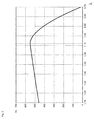
- FIG. 2 a measurement course of the sensor device according to the invention according to the embodiment is shown.
- the air ratio was determined in the gas stream by a conventional gas analyzer.
- the scaling of the intensity axis (Y-axis) has been chosen for a qualitative representation of the measured values.
- the linear increase in the intensity change from 1.70 to 1.10 can be explained by the fact that there is always less excess air and therefore the temperature of the reaction layer rises around the heating wire. This ensures that more radicals are formed and the reaction layer around the heating wire expands and / or increases the density of the water-forming, exothermic chemical reaction processes, resulting in a higher light emission in the wavelength range around 1000 nm.
- the senor according to the invention offers a further possible use.
- both the mixture ratio varies and the temperature of the heating wire is reduced until a point is found, which still allows a reaction mode with radiation emission, but from which in the direction of a lean and richer mixture in each case a collapse of the reaction (disappearance of the radiation).
- the heating wire is re-regulated to a normal operating temperature while maintaining the so-regulated fuel gas-air ratio.
- the point of the above-mentioned maximum of the radiation intensity is a fixed point depending on the type of gas.
- the inventive method and the sensor according to the invention are to be modified in many ways.
- the sensor may be constructed in several parts and in principle it is also possible to provide a gas discharge on the sensor, instead of guiding the gas into the gas stream. It is essential that a portion of the gas stream is branched off and that the emitted radiation of a controlled exothermic chemical reaction is measured optically to determine the air ratio. Then, an optimization of the fuel gas-air mixture can be made.
- the known methods from the state of the art, in which essentially electrochemical effects are used to determine the air number thus provide an alternative with an optical measurement of a chemical test reaction at the side.
- the chemical test reaction takes place at any time controlled and in such a dimensioned structure that no self-sustaining or uncontrolled chemical reaction of the fuel gas-air mixture in the measuring chamber is possible.
Landscapes
- Health & Medical Sciences (AREA)
- Chemical & Material Sciences (AREA)
- Life Sciences & Earth Sciences (AREA)
- Physics & Mathematics (AREA)
- Pathology (AREA)
- Biochemistry (AREA)
- General Health & Medical Sciences (AREA)
- General Physics & Mathematics (AREA)
- Immunology (AREA)
- Analytical Chemistry (AREA)
- Engineering & Computer Science (AREA)
- Nuclear Medicine, Radiotherapy & Molecular Imaging (AREA)
- Chemical Kinetics & Catalysis (AREA)
- Plasma & Fusion (AREA)
- Oil, Petroleum & Natural Gas (AREA)
- General Chemical & Material Sciences (AREA)
- Food Science & Technology (AREA)
- Medicinal Chemistry (AREA)
- Molecular Biology (AREA)
- Biomedical Technology (AREA)
- Investigating, Analyzing Materials By Fluorescence Or Luminescence (AREA)
- Investigating Or Analysing Materials By Optical Means (AREA)
Priority Applications (2)
| Application Number | Priority Date | Filing Date | Title |
|---|---|---|---|
| EP16154849.0A EP3206017B1 (fr) | 2016-02-09 | 2016-02-09 | Capteur et dispositif de determination du coefficient d'air d'un melange gaz combustible/air |
| US15/428,861 US10545127B2 (en) | 2016-02-09 | 2017-02-09 | Sensor and method for determining the air ratio of a fuel gas/air mixture |
Applications Claiming Priority (1)
| Application Number | Priority Date | Filing Date | Title |
|---|---|---|---|
| EP16154849.0A EP3206017B1 (fr) | 2016-02-09 | 2016-02-09 | Capteur et dispositif de determination du coefficient d'air d'un melange gaz combustible/air |
Publications (2)
| Publication Number | Publication Date |
|---|---|
| EP3206017A1 true EP3206017A1 (fr) | 2017-08-16 |
| EP3206017B1 EP3206017B1 (fr) | 2018-09-12 |
Family
ID=55405127
Family Applications (1)
| Application Number | Title | Priority Date | Filing Date |
|---|---|---|---|
| EP16154849.0A Active EP3206017B1 (fr) | 2016-02-09 | 2016-02-09 | Capteur et dispositif de determination du coefficient d'air d'un melange gaz combustible/air |
Country Status (2)
| Country | Link |
|---|---|
| US (1) | US10545127B2 (fr) |
| EP (1) | EP3206017B1 (fr) |
Cited By (1)
| Publication number | Priority date | Publication date | Assignee | Title |
|---|---|---|---|---|
| EP3757551A1 (fr) | 2019-06-26 | 2020-12-30 | Ademco 2 GmbH | Capteur et procédé permettant de déterminer un coefficient d'air d'un mélange air/gaz combustible |
Families Citing this family (1)
| Publication number | Priority date | Publication date | Assignee | Title |
|---|---|---|---|---|
| DE102019101191B4 (de) * | 2019-01-17 | 2025-02-20 | Ebm-Papst Landshut Gmbh | Verfahren zur Regelung eines Gasgemisches unter Nutzung eines Gassensors und eines Gasgemischsensors |
Citations (8)
| Publication number | Priority date | Publication date | Assignee | Title |
|---|---|---|---|---|
| EP0156200A1 (fr) * | 1984-03-08 | 1985-10-02 | Ruhrgas Aktiengesellschaft | Méthode et dispositif pour déterminer le rapport de mélange d'un mélange contenant un gaz porteur d'oxygène et un carburant |
| DE4121924A1 (de) * | 1990-07-25 | 1992-02-06 | Carrier Corp | Verfahren und vorrichtung zur optimierung des brennstoff-luftverhaeltnisses in der brenngaszufuehrung eines strahlungsbrenners |
| FR2816056A1 (fr) * | 2000-11-02 | 2002-05-03 | Centre Nat Rech Scient | Dispositif de mesure de richesse d'une combustion et procede afferent de reglage |
| US20030003590A1 (en) * | 2001-06-28 | 2003-01-02 | Abbasi Hamid A. | Method for measuring concentrations of gases and vapors using controlled flames |
| EP1591723A2 (fr) * | 2004-04-27 | 2005-11-02 | BBT Thermotechnik GmbH | Electrode |
| WO2009144051A1 (fr) | 2008-05-27 | 2009-12-03 | Robert Bosch Gmbh | Sonde lambda avec référence alternante |
| WO2015054323A1 (fr) * | 2013-10-07 | 2015-04-16 | Clearsign Combustion Corporation | Brûleur à prémélangé à stabilisateur perforé |
| CN104823041A (zh) * | 2013-09-25 | 2015-08-05 | 韩国生产技术研究院 | 包括光传感器的空燃比测量系统 |
Family Cites Families (24)
| Publication number | Priority date | Publication date | Assignee | Title |
|---|---|---|---|---|
| US4367130A (en) * | 1970-11-30 | 1983-01-04 | Lemelson Jerome H | Chemical reaction |
| US3960495A (en) * | 1972-02-15 | 1976-06-01 | Anthony Desmond Shand Tantram | Detection of combustible gases |
| US3955921A (en) * | 1972-09-19 | 1976-05-11 | Eli Lilly And Company | Method of killing microorganisms in the inside of a container utilizing a laser beam induced plasma |
| US3865707A (en) * | 1972-12-27 | 1975-02-11 | Donald A Sayles | Combustible mixture analyzer |
| DE2902125A1 (de) * | 1978-02-07 | 1979-08-09 | Mather & Platt Ltd | Verfahren und einrichtung zur ermittlung der anwesenheit von gasen oder daempfen in luft oder anderen gasfoermigen medien |
| GB2110818B (en) * | 1981-11-14 | 1985-05-15 | Ferranti Ltd | Non-dispersive gas analyser |
| US4517161A (en) * | 1982-09-29 | 1985-05-14 | Grumman Aerospace Corp. | Combustible vapor detection system |
| FR2592320B1 (fr) * | 1985-12-30 | 1988-04-08 | Inst Francais Du Petrole | Nouveau procede d'oxydation d'une charge oxydable en phase gazeuse et reacteur pour la mise en oeuvre de ce procede. |
| JPH01237435A (ja) * | 1988-03-18 | 1989-09-21 | Mitsubishi Heavy Ind Ltd | エンジンの空燃比測定方法 |
| US5314249A (en) * | 1991-11-19 | 1994-05-24 | Kawasaki Steel Corporation | Surface condition measurement apparatus |
| WO1995028633A1 (fr) * | 1994-04-14 | 1995-10-26 | William Henry Marlow | Mesure de precurseurs de detonation et/ou de deflagration |
| US5599179A (en) * | 1994-08-01 | 1997-02-04 | Mississippi State University | Real-time combustion controller |
| US5820260A (en) * | 1996-07-12 | 1998-10-13 | Badger Meter, Inc. | Measuring heating value using predetermined volumes in non-catialytic combustion |
| FR2790316B1 (fr) * | 1999-02-25 | 2001-11-23 | Oldham France Sa | Procede d'analyse d'un melange gazeux pour la determination de son explosibilite et dispositif pour la mise en oeuvre d'un tel procede |
| US6237575B1 (en) * | 1999-04-08 | 2001-05-29 | Engelhard Corporation | Dynamic infrared sensor for automotive pre-vaporized fueling control |
| US6640199B1 (en) * | 2001-10-24 | 2003-10-28 | Spectral Sciences, Inc. | System and method for optically determining properties of hot fluids from the spectral structure of emitted radiation |
| US6843075B2 (en) * | 2002-04-23 | 2005-01-18 | Johns Manville International, Inc. | Method for controlling process variables and an optical temperature sensor assembly |
| AU2003258966A1 (en) * | 2002-06-27 | 2004-01-19 | Control Instruments | Gas analyzer for measuring the flammability of mixtures of combustible gases and oxygen |
| US6977179B2 (en) * | 2004-03-19 | 2005-12-20 | Gas Technology Institute | Method and apparatus for measuring the heating value of a single or multi-component fuel gas |
| AT503276B1 (de) * | 2007-05-31 | 2010-06-15 | Avl List Gmbh | Verfahren zur bewertung des zustandes eines kraftstoff/luft-gemisches |
| US8625098B2 (en) * | 2010-12-17 | 2014-01-07 | General Electric Company | System and method for real-time measurement of equivalence ratio of gas fuel mixture |
| CN103502810B (zh) * | 2011-03-07 | 2017-12-08 | 国立大学法人东北大学 | 燃料物性决定方法以及燃料物性决定装置 |
| US20160348901A1 (en) * | 2013-02-14 | 2016-12-01 | Clearsign Combustion Corporation | Electrically heated burner |
| JP6441643B2 (ja) * | 2013-11-29 | 2018-12-19 | 日本特殊陶業株式会社 | ガス検出器 |
-
2016
- 2016-02-09 EP EP16154849.0A patent/EP3206017B1/fr active Active
-
2017
- 2017-02-09 US US15/428,861 patent/US10545127B2/en active Active
Patent Citations (8)
| Publication number | Priority date | Publication date | Assignee | Title |
|---|---|---|---|---|
| EP0156200A1 (fr) * | 1984-03-08 | 1985-10-02 | Ruhrgas Aktiengesellschaft | Méthode et dispositif pour déterminer le rapport de mélange d'un mélange contenant un gaz porteur d'oxygène et un carburant |
| DE4121924A1 (de) * | 1990-07-25 | 1992-02-06 | Carrier Corp | Verfahren und vorrichtung zur optimierung des brennstoff-luftverhaeltnisses in der brenngaszufuehrung eines strahlungsbrenners |
| FR2816056A1 (fr) * | 2000-11-02 | 2002-05-03 | Centre Nat Rech Scient | Dispositif de mesure de richesse d'une combustion et procede afferent de reglage |
| US20030003590A1 (en) * | 2001-06-28 | 2003-01-02 | Abbasi Hamid A. | Method for measuring concentrations of gases and vapors using controlled flames |
| EP1591723A2 (fr) * | 2004-04-27 | 2005-11-02 | BBT Thermotechnik GmbH | Electrode |
| WO2009144051A1 (fr) | 2008-05-27 | 2009-12-03 | Robert Bosch Gmbh | Sonde lambda avec référence alternante |
| CN104823041A (zh) * | 2013-09-25 | 2015-08-05 | 韩国生产技术研究院 | 包括光传感器的空燃比测量系统 |
| WO2015054323A1 (fr) * | 2013-10-07 | 2015-04-16 | Clearsign Combustion Corporation | Brûleur à prémélangé à stabilisateur perforé |
Non-Patent Citations (1)
| Title |
|---|
| R. GÜNTHER: "Verbrennung und Feuerungen", 2013, SPRINGER-VERLAG |
Cited By (1)
| Publication number | Priority date | Publication date | Assignee | Title |
|---|---|---|---|---|
| EP3757551A1 (fr) | 2019-06-26 | 2020-12-30 | Ademco 2 GmbH | Capteur et procédé permettant de déterminer un coefficient d'air d'un mélange air/gaz combustible |
Also Published As
| Publication number | Publication date |
|---|---|
| US10545127B2 (en) | 2020-01-28 |
| EP3206017B1 (fr) | 2018-09-12 |
| US20170227514A1 (en) | 2017-08-10 |
Similar Documents
| Publication | Publication Date | Title |
|---|---|---|
| EP1183520B1 (fr) | Dispositif de capteur de gaz | |
| EP3663648B1 (fr) | Dispositif de régulation du rapport de mélange de l'air de combustion et de gaz de combustion dans un processus de combustion | |
| DE2705308C2 (de) | Vorrichtung zum Aufheizen eines Graphitrohres in einer Graphitrohrküvette eines Atomabsorptionsspektrometers | |
| DE4008816C2 (fr) | ||
| WO2010060686A1 (fr) | Capteur optique pour mesurer la concentration d'un constituant d'un effluent gazeux | |
| WO1998040673A1 (fr) | Procede et dispositif pour l'analyse de la combustion et la surveillance d'une flamme dans une chambre de combustion | |
| WO2008015292A1 (fr) | Procédé et dispositif pour la surveillance d'un processus de combustion | |
| DE3044959A1 (de) | Flammenfotometer-nachweisanalysator | |
| CH697670B1 (de) | Sensor zum Überwachen einer Konzentration gasförmiger Brennstoffe in einer Brennkammer. | |
| EP3206017B1 (fr) | Capteur et dispositif de determination du coefficient d'air d'un melange gaz combustible/air | |
| DE102017218084A1 (de) | Partikelsensoreinheit mit einem optischen Partikelsensor | |
| EP4043873A1 (fr) | Dispositif de détection de gaz et procédé de détection de gaz au moyen d'un détecteur et d'un modulateur | |
| EP3364170B1 (fr) | Mesure de la concentration de gaz dans un récipient | |
| EP0421100B1 (fr) | Procédé et dispositif pour reconnaître des conditions dangereuses dans une pièce | |
| WO2020104111A1 (fr) | Procédé pour faire fonctionner un capteur de particules | |
| CA3026698A1 (fr) | Analyse de particule simple employant la detection optique | |
| WO2014180716A1 (fr) | Capteur de gaz et procédé de détection d'au moins un composant gazeux | |
| DE4023649A1 (de) | Verfahren und vorrichtung zum erkennen von gefahrenzustaenden in einem raum | |
| EP3995817B1 (fr) | Procédé et agencement de détection de l'hydrogène dans un appareil de chauffage pouvant fonctionner avec de l'hydrogène ou du gaz combustible contenant de l'hydrogène | |
| DE10153643A1 (de) | Verfahren und Vorrichtung zur Überwachung und Optimierung einer Verbrennungsanlage | |
| WO2004031744A1 (fr) | Procede et cellule de mesure de gaz destines a la detection de differents gaz | |
| DE102009004059B4 (de) | Glühkerze | |
| WO2004008113A1 (fr) | Spectrometre d'absorption et procede de mesure correspondant | |
| DE202016102767U1 (de) | Tragbare Vorrichtung zum Messen von flüchtigen chemischen Stoffen | |
| DE102021116344A1 (de) | Verfahren und Anordnung zur Beobachtung von Verbrennungsvorgängen sowie Computerprogramprodukt |
Legal Events
| Date | Code | Title | Description |
|---|---|---|---|
| PUAI | Public reference made under article 153(3) epc to a published international application that has entered the european phase |
Free format text: ORIGINAL CODE: 0009012 |
|
| STAA | Information on the status of an ep patent application or granted ep patent |
Free format text: STATUS: THE APPLICATION HAS BEEN PUBLISHED |
|
| AK | Designated contracting states |
Kind code of ref document: A1 Designated state(s): AL AT BE BG CH CY CZ DE DK EE ES FI FR GB GR HR HU IE IS IT LI LT LU LV MC MK MT NL NO PL PT RO RS SE SI SK SM TR |
|
| AX | Request for extension of the european patent |
Extension state: BA ME |
|
| STAA | Information on the status of an ep patent application or granted ep patent |
Free format text: STATUS: REQUEST FOR EXAMINATION WAS MADE |
|
| 17P | Request for examination filed |
Effective date: 20171025 |
|
| RBV | Designated contracting states (corrected) |
Designated state(s): AL AT BE BG CH CY CZ DE DK EE ES FI FR GB GR HR HU IE IS IT LI LT LU LV MC MK MT NL NO PL PT RO RS SE SI SK SM TR |
|
| STAA | Information on the status of an ep patent application or granted ep patent |
Free format text: STATUS: EXAMINATION IS IN PROGRESS |
|
| 17Q | First examination report despatched |
Effective date: 20180130 |
|
| RIC1 | Information provided on ipc code assigned before grant |
Ipc: F02D 41/00 20060101ALI20180406BHEP Ipc: F23N 5/00 20060101ALI20180406BHEP Ipc: G01N 21/67 20060101ALI20180406BHEP Ipc: G01N 21/76 20060101ALI20180406BHEP Ipc: G01N 1/22 20060101ALI20180406BHEP Ipc: G01N 21/63 20060101AFI20180406BHEP Ipc: G01N 21/71 20060101ALI20180406BHEP Ipc: G01N 33/22 20060101ALI20180406BHEP |
|
| GRAP | Despatch of communication of intention to grant a patent |
Free format text: ORIGINAL CODE: EPIDOSNIGR1 |
|
| STAA | Information on the status of an ep patent application or granted ep patent |
Free format text: STATUS: GRANT OF PATENT IS INTENDED |
|
| INTG | Intention to grant announced |
Effective date: 20180523 |
|
| GRAS | Grant fee paid |
Free format text: ORIGINAL CODE: EPIDOSNIGR3 |
|
| GRAA | (expected) grant |
Free format text: ORIGINAL CODE: 0009210 |
|
| STAA | Information on the status of an ep patent application or granted ep patent |
Free format text: STATUS: THE PATENT HAS BEEN GRANTED |
|
| AK | Designated contracting states |
Kind code of ref document: B1 Designated state(s): AL AT BE BG CH CY CZ DE DK EE ES FI FR GB GR HR HU IE IS IT LI LT LU LV MC MK MT NL NO PL PT RO RS SE SI SK SM TR |
|
| REG | Reference to a national code |
Ref country code: GB Ref legal event code: FG4D Free format text: NOT ENGLISH |
|
| REG | Reference to a national code |
Ref country code: CH Ref legal event code: EP |
|
| REG | Reference to a national code |
Ref country code: IE Ref legal event code: FG4D Free format text: LANGUAGE OF EP DOCUMENT: GERMAN |
|
| REG | Reference to a national code |
Ref country code: DE Ref legal event code: R096 Ref document number: 502016001886 Country of ref document: DE |
|
| REG | Reference to a national code |
Ref country code: AT Ref legal event code: REF Ref document number: 1041196 Country of ref document: AT Kind code of ref document: T Effective date: 20181015 |
|
| REG | Reference to a national code |
Ref country code: NL Ref legal event code: MP Effective date: 20180912 |
|
| REG | Reference to a national code |
Ref country code: LT Ref legal event code: MG4D |
|
| PG25 | Lapsed in a contracting state [announced via postgrant information from national office to epo] |
Ref country code: RS Free format text: LAPSE BECAUSE OF FAILURE TO SUBMIT A TRANSLATION OF THE DESCRIPTION OR TO PAY THE FEE WITHIN THE PRESCRIBED TIME-LIMIT Effective date: 20180912 Ref country code: LT Free format text: LAPSE BECAUSE OF FAILURE TO SUBMIT A TRANSLATION OF THE DESCRIPTION OR TO PAY THE FEE WITHIN THE PRESCRIBED TIME-LIMIT Effective date: 20180912 Ref country code: BG Free format text: LAPSE BECAUSE OF FAILURE TO SUBMIT A TRANSLATION OF THE DESCRIPTION OR TO PAY THE FEE WITHIN THE PRESCRIBED TIME-LIMIT Effective date: 20181212 Ref country code: SE Free format text: LAPSE BECAUSE OF FAILURE TO SUBMIT A TRANSLATION OF THE DESCRIPTION OR TO PAY THE FEE WITHIN THE PRESCRIBED TIME-LIMIT Effective date: 20180912 Ref country code: FI Free format text: LAPSE BECAUSE OF FAILURE TO SUBMIT A TRANSLATION OF THE DESCRIPTION OR TO PAY THE FEE WITHIN THE PRESCRIBED TIME-LIMIT Effective date: 20180912 Ref country code: GR Free format text: LAPSE BECAUSE OF FAILURE TO SUBMIT A TRANSLATION OF THE DESCRIPTION OR TO PAY THE FEE WITHIN THE PRESCRIBED TIME-LIMIT Effective date: 20181213 Ref country code: NO Free format text: LAPSE BECAUSE OF FAILURE TO SUBMIT A TRANSLATION OF THE DESCRIPTION OR TO PAY THE FEE WITHIN THE PRESCRIBED TIME-LIMIT Effective date: 20181212 |
|
| PG25 | Lapsed in a contracting state [announced via postgrant information from national office to epo] |
Ref country code: LV Free format text: LAPSE BECAUSE OF FAILURE TO SUBMIT A TRANSLATION OF THE DESCRIPTION OR TO PAY THE FEE WITHIN THE PRESCRIBED TIME-LIMIT Effective date: 20180912 Ref country code: HR Free format text: LAPSE BECAUSE OF FAILURE TO SUBMIT A TRANSLATION OF THE DESCRIPTION OR TO PAY THE FEE WITHIN THE PRESCRIBED TIME-LIMIT Effective date: 20180912 Ref country code: AL Free format text: LAPSE BECAUSE OF FAILURE TO SUBMIT A TRANSLATION OF THE DESCRIPTION OR TO PAY THE FEE WITHIN THE PRESCRIBED TIME-LIMIT Effective date: 20180912 |
|
| PG25 | Lapsed in a contracting state [announced via postgrant information from national office to epo] |
Ref country code: RO Free format text: LAPSE BECAUSE OF FAILURE TO SUBMIT A TRANSLATION OF THE DESCRIPTION OR TO PAY THE FEE WITHIN THE PRESCRIBED TIME-LIMIT Effective date: 20180912 Ref country code: IT Free format text: LAPSE BECAUSE OF FAILURE TO SUBMIT A TRANSLATION OF THE DESCRIPTION OR TO PAY THE FEE WITHIN THE PRESCRIBED TIME-LIMIT Effective date: 20180912 Ref country code: CZ Free format text: LAPSE BECAUSE OF FAILURE TO SUBMIT A TRANSLATION OF THE DESCRIPTION OR TO PAY THE FEE WITHIN THE PRESCRIBED TIME-LIMIT Effective date: 20180912 Ref country code: PL Free format text: LAPSE BECAUSE OF FAILURE TO SUBMIT A TRANSLATION OF THE DESCRIPTION OR TO PAY THE FEE WITHIN THE PRESCRIBED TIME-LIMIT Effective date: 20180912 Ref country code: IS Free format text: LAPSE BECAUSE OF FAILURE TO SUBMIT A TRANSLATION OF THE DESCRIPTION OR TO PAY THE FEE WITHIN THE PRESCRIBED TIME-LIMIT Effective date: 20190112 Ref country code: ES Free format text: LAPSE BECAUSE OF FAILURE TO SUBMIT A TRANSLATION OF THE DESCRIPTION OR TO PAY THE FEE WITHIN THE PRESCRIBED TIME-LIMIT Effective date: 20180912 Ref country code: NL Free format text: LAPSE BECAUSE OF FAILURE TO SUBMIT A TRANSLATION OF THE DESCRIPTION OR TO PAY THE FEE WITHIN THE PRESCRIBED TIME-LIMIT Effective date: 20180912 Ref country code: EE Free format text: LAPSE BECAUSE OF FAILURE TO SUBMIT A TRANSLATION OF THE DESCRIPTION OR TO PAY THE FEE WITHIN THE PRESCRIBED TIME-LIMIT Effective date: 20180912 |
|
| PG25 | Lapsed in a contracting state [announced via postgrant information from national office to epo] |
Ref country code: SM Free format text: LAPSE BECAUSE OF FAILURE TO SUBMIT A TRANSLATION OF THE DESCRIPTION OR TO PAY THE FEE WITHIN THE PRESCRIBED TIME-LIMIT Effective date: 20180912 Ref country code: SK Free format text: LAPSE BECAUSE OF FAILURE TO SUBMIT A TRANSLATION OF THE DESCRIPTION OR TO PAY THE FEE WITHIN THE PRESCRIBED TIME-LIMIT Effective date: 20180912 Ref country code: PT Free format text: LAPSE BECAUSE OF FAILURE TO SUBMIT A TRANSLATION OF THE DESCRIPTION OR TO PAY THE FEE WITHIN THE PRESCRIBED TIME-LIMIT Effective date: 20190112 |
|
| REG | Reference to a national code |
Ref country code: DE Ref legal event code: R097 Ref document number: 502016001886 Country of ref document: DE |
|
| PLBE | No opposition filed within time limit |
Free format text: ORIGINAL CODE: 0009261 |
|
| STAA | Information on the status of an ep patent application or granted ep patent |
Free format text: STATUS: NO OPPOSITION FILED WITHIN TIME LIMIT |
|
| PG25 | Lapsed in a contracting state [announced via postgrant information from national office to epo] |
Ref country code: DK Free format text: LAPSE BECAUSE OF FAILURE TO SUBMIT A TRANSLATION OF THE DESCRIPTION OR TO PAY THE FEE WITHIN THE PRESCRIBED TIME-LIMIT Effective date: 20180912 |
|
| 26N | No opposition filed |
Effective date: 20190613 |
|
| PG25 | Lapsed in a contracting state [announced via postgrant information from national office to epo] |
Ref country code: SI Free format text: LAPSE BECAUSE OF FAILURE TO SUBMIT A TRANSLATION OF THE DESCRIPTION OR TO PAY THE FEE WITHIN THE PRESCRIBED TIME-LIMIT Effective date: 20180912 |
|
| REG | Reference to a national code |
Ref country code: CH Ref legal event code: PL |
|
| PG25 | Lapsed in a contracting state [announced via postgrant information from national office to epo] |
Ref country code: MC Free format text: LAPSE BECAUSE OF FAILURE TO SUBMIT A TRANSLATION OF THE DESCRIPTION OR TO PAY THE FEE WITHIN THE PRESCRIBED TIME-LIMIT Effective date: 20180912 Ref country code: LU Free format text: LAPSE BECAUSE OF NON-PAYMENT OF DUE FEES Effective date: 20190209 |
|
| REG | Reference to a national code |
Ref country code: BE Ref legal event code: MM Effective date: 20190228 |
|
| REG | Reference to a national code |
Ref country code: IE Ref legal event code: MM4A |
|
| PG25 | Lapsed in a contracting state [announced via postgrant information from national office to epo] |
Ref country code: CH Free format text: LAPSE BECAUSE OF NON-PAYMENT OF DUE FEES Effective date: 20190228 Ref country code: LI Free format text: LAPSE BECAUSE OF NON-PAYMENT OF DUE FEES Effective date: 20190228 |
|
| PG25 | Lapsed in a contracting state [announced via postgrant information from national office to epo] |
Ref country code: IE Free format text: LAPSE BECAUSE OF NON-PAYMENT OF DUE FEES Effective date: 20190209 |
|
| PG25 | Lapsed in a contracting state [announced via postgrant information from national office to epo] |
Ref country code: BE Free format text: LAPSE BECAUSE OF NON-PAYMENT OF DUE FEES Effective date: 20190228 |
|
| PG25 | Lapsed in a contracting state [announced via postgrant information from national office to epo] |
Ref country code: TR Free format text: LAPSE BECAUSE OF FAILURE TO SUBMIT A TRANSLATION OF THE DESCRIPTION OR TO PAY THE FEE WITHIN THE PRESCRIBED TIME-LIMIT Effective date: 20180912 |
|
| PG25 | Lapsed in a contracting state [announced via postgrant information from national office to epo] |
Ref country code: MT Free format text: LAPSE BECAUSE OF FAILURE TO SUBMIT A TRANSLATION OF THE DESCRIPTION OR TO PAY THE FEE WITHIN THE PRESCRIBED TIME-LIMIT Effective date: 20180912 |
|
| PG25 | Lapsed in a contracting state [announced via postgrant information from national office to epo] |
Ref country code: CY Free format text: LAPSE BECAUSE OF FAILURE TO SUBMIT A TRANSLATION OF THE DESCRIPTION OR TO PAY THE FEE WITHIN THE PRESCRIBED TIME-LIMIT Effective date: 20180912 |
|
| REG | Reference to a national code |
Ref country code: DE Ref legal event code: R082 Ref document number: 502016001886 Country of ref document: DE Representative=s name: ZENZ PATENTANWAELTE PARTNERSCHAFT MBB, DE Ref country code: DE Ref legal event code: R081 Ref document number: 502016001886 Country of ref document: DE Owner name: ADEMCO 2 GMBH, DE Free format text: FORMER OWNER: ELSTER GMBH, 55252 MAINZ-KASTEL, DE |
|
| PG25 | Lapsed in a contracting state [announced via postgrant information from national office to epo] |
Ref country code: HU Free format text: LAPSE BECAUSE OF FAILURE TO SUBMIT A TRANSLATION OF THE DESCRIPTION OR TO PAY THE FEE WITHIN THE PRESCRIBED TIME-LIMIT; INVALID AB INITIO Effective date: 20160209 |
|
| REG | Reference to a national code |
Ref country code: AT Ref legal event code: MM01 Ref document number: 1041196 Country of ref document: AT Kind code of ref document: T Effective date: 20210209 |
|
| PG25 | Lapsed in a contracting state [announced via postgrant information from national office to epo] |
Ref country code: AT Free format text: LAPSE BECAUSE OF NON-PAYMENT OF DUE FEES Effective date: 20210209 |
|
| PG25 | Lapsed in a contracting state [announced via postgrant information from national office to epo] |
Ref country code: MK Free format text: LAPSE BECAUSE OF FAILURE TO SUBMIT A TRANSLATION OF THE DESCRIPTION OR TO PAY THE FEE WITHIN THE PRESCRIBED TIME-LIMIT Effective date: 20180912 |
|
| P01 | Opt-out of the competence of the unified patent court (upc) registered |
Effective date: 20230601 |
|
| PGFP | Annual fee paid to national office [announced via postgrant information from national office to epo] |
Ref country code: GB Payment date: 20260223 Year of fee payment: 11 |
|
| PGFP | Annual fee paid to national office [announced via postgrant information from national office to epo] |
Ref country code: DE Payment date: 20260320 Year of fee payment: 11 |
|
| PGFP | Annual fee paid to national office [announced via postgrant information from national office to epo] |
Ref country code: FR Payment date: 20260224 Year of fee payment: 11 |