EP3206074B1 - Optisches abtastsystem sowie lichtprojektions- und empfangsvorrichtung - Google Patents
Optisches abtastsystem sowie lichtprojektions- und empfangsvorrichtung Download PDFInfo
- Publication number
- EP3206074B1 EP3206074B1 EP15849446.8A EP15849446A EP3206074B1 EP 3206074 B1 EP3206074 B1 EP 3206074B1 EP 15849446 A EP15849446 A EP 15849446A EP 3206074 B1 EP3206074 B1 EP 3206074B1
- Authority
- EP
- European Patent Office
- Prior art keywords
- light
- mirror surface
- mirror
- light flux
- angle
- Prior art date
- Legal status (The legal status is an assumption and is not a legal conclusion. Google has not performed a legal analysis and makes no representation as to the accuracy of the status listed.)
- Active
Links
Images






Classifications
-
- G—PHYSICS
- G02—OPTICS
- G02B—OPTICAL ELEMENTS, SYSTEMS OR APPARATUS
- G02B26/00—Optical devices or arrangements for the control of light using movable or deformable optical elements
- G02B26/08—Optical devices or arrangements for the control of light using movable or deformable optical elements for controlling the direction of light
- G02B26/10—Scanning systems
- G02B26/12—Scanning systems using multifaceted mirrors
- G02B26/129—Systems in which the scanning light beam is repeatedly reflected from the polygonal mirror
-
- G—PHYSICS
- G01—MEASURING; TESTING
- G01S—RADIO DIRECTION-FINDING; RADIO NAVIGATION; DETERMINING DISTANCE OR VELOCITY BY USE OF RADIO WAVES; LOCATING OR PRESENCE-DETECTING BY USE OF THE REFLECTION OR RERADIATION OF RADIO WAVES; ANALOGOUS ARRANGEMENTS USING OTHER WAVES
- G01S7/00—Details of systems according to groups G01S13/00, G01S15/00, G01S17/00
- G01S7/48—Details of systems according to groups G01S13/00, G01S15/00, G01S17/00 of systems according to group G01S17/00
- G01S7/481—Constructional features, e.g. arrangements of optical elements
-
- G—PHYSICS
- G01—MEASURING; TESTING
- G01S—RADIO DIRECTION-FINDING; RADIO NAVIGATION; DETERMINING DISTANCE OR VELOCITY BY USE OF RADIO WAVES; LOCATING OR PRESENCE-DETECTING BY USE OF THE REFLECTION OR RERADIATION OF RADIO WAVES; ANALOGOUS ARRANGEMENTS USING OTHER WAVES
- G01S7/00—Details of systems according to groups G01S13/00, G01S15/00, G01S17/00
- G01S7/48—Details of systems according to groups G01S13/00, G01S15/00, G01S17/00 of systems according to group G01S17/00
- G01S7/481—Constructional features, e.g. arrangements of optical elements
- G01S7/4817—Constructional features, e.g. arrangements of optical elements relating to scanning
-
- G—PHYSICS
- G02—OPTICS
- G02B—OPTICAL ELEMENTS, SYSTEMS OR APPARATUS
- G02B26/00—Optical devices or arrangements for the control of light using movable or deformable optical elements
- G02B26/08—Optical devices or arrangements for the control of light using movable or deformable optical elements for controlling the direction of light
- G02B26/10—Scanning systems
-
- G—PHYSICS
- G02—OPTICS
- G02B—OPTICAL ELEMENTS, SYSTEMS OR APPARATUS
- G02B26/00—Optical devices or arrangements for the control of light using movable or deformable optical elements
- G02B26/08—Optical devices or arrangements for the control of light using movable or deformable optical elements for controlling the direction of light
- G02B26/10—Scanning systems
- G02B26/12—Scanning systems using multifaceted mirrors
-
- G—PHYSICS
- G02—OPTICS
- G02B—OPTICAL ELEMENTS, SYSTEMS OR APPARATUS
- G02B26/00—Optical devices or arrangements for the control of light using movable or deformable optical elements
- G02B26/08—Optical devices or arrangements for the control of light using movable or deformable optical elements for controlling the direction of light
- G02B26/10—Scanning systems
- G02B26/12—Scanning systems using multifaceted mirrors
- G02B26/125—Details of the optical system between the polygonal mirror and the image plane
- G02B26/126—Details of the optical system between the polygonal mirror and the image plane including curved mirrors
-
- G—PHYSICS
- G02—OPTICS
- G02B—OPTICAL ELEMENTS, SYSTEMS OR APPARATUS
- G02B27/00—Optical systems or apparatus not provided for by any of the groups G02B1/00 - G02B26/00, G02B30/00
- G02B27/0025—Optical systems or apparatus not provided for by any of the groups G02B1/00 - G02B26/00, G02B30/00 for optical correction, e.g. distorsion, aberration
- G02B27/0031—Optical systems or apparatus not provided for by any of the groups G02B1/00 - G02B26/00, G02B30/00 for optical correction, e.g. distorsion, aberration for scanning purposes
-
- G—PHYSICS
- G02—OPTICS
- G02B—OPTICAL ELEMENTS, SYSTEMS OR APPARATUS
- G02B5/00—Optical elements other than lenses
- G02B5/08—Mirrors
- G02B5/09—Multifaceted or polygonal mirrors, e.g. polygonal scanning mirrors; Fresnel mirrors
Definitions
- the present invention relates to a scanning optical system suitably used for a light projecting and receiving apparatus which irradiates a laser light flux and the like so as to detect an object and to a light projecting and receiving apparatus.
- laser radars which are distance measuring apparatuses utilizing optical scanning
- General laser radars are configured to rotate or oscillate a mirror, a polygon mirror or the like while projecting light fluxes emitted from a laser light source onto the mirror, the polygon mirror, or the like so as to scan a wide range and to receive scattered light rays from a light-projected object with a light receiving element, thereby performing shape measurement and distance measurement.
- Document JP S50-109737A discloses a technique with regard to a polygon mirror which includes the even number of planar reflective surfaces and performs scanning by reflecting light rays the even number of times. It is also referred to the documents US5028103 , DE202005005448U and US2009195848 that disclose similar systems.
- the present invention has been achieved in view of the above-mentioned circumstances, and an object of the present invention is to provide a scanning optical system which can obtain a reflected light flux with sufficient intensity to a measurement object in a wide range, and a light projecting and receiving apparatus.
- a scanning optical system with the features of claim 1 is provided. Preferred embodiments are described in the dependent claims. Disclosed is a scanning optical system that includes:
- a scanning optical system which can obtain a reflected light flux with sufficient intensity to a measurement object in a wide range, and a radar.
- a main scanning angle means an azimuthal angle of the center of a rotation axis of a projected light flux deflected by a mirror unit
- a sub-scanning angle means an elevation/depression angle of a projected light flux with reference to a plane, made as a standard, orthogonal to a rotation axis
- a spot rotation angle means an angle of the orientation of a light flux rotating around a light projecting direction serving as a rotation center
- longitudinal distortion means a deviation of an angle in the sub-scanning direction at the time of scanning a periphery with respect to an angle in the sub-scanning direction at the center of the main scanning direction.
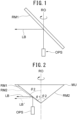
- the width of a light flux in the sub-scanning direction has been unable to be made longer as compared with the width of a light flux in the main scanning direction. That is, in the case where the cross sectional shape of the spot light SL is, for example, a round shape or a shape (an aspect ratio) in which a length in the main scanning angle direction is approximately the same with a length in the sub-scanning angle direction, there is no problem. However, in the case where a length in the main scanning angle direction is different from a length in the sub-scanning angle direction, problems may arise.
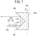
- Fig. 7 is a cross sectional view, along a rotation axis RO, showing a scanning optical system of the present embodiment.
- Fig. 8(a) is a front view of the scanning optical system of the present embodiment
- Fig. 8(b) is a view seeing in the direction of a rotation axis and showing a state of the center of the main scanning angle.
- Fig. 9(a) is a front view of a scanning optical system of the present embodiment
- Fig. 9(b) is a view seeing in the direction of a rotation axis and showing a state of the periphery of the main scanning angle.
- the scanning optical system is constituted by a mirror unit MU and a light projecting system LPS.
- a cross section of a spot light orthogonal to the proceeding direction is assumed to be similar to that in the comparative example.
- an optical axis SO of a light projecting system LPS including a semiconductor laser LD as a light source and a collimator lens CL is disposed so as to be orthogonal to a rotation axis RO of a mirror unit MU including a first mirror surface M1 and a second mirror surface M2.
- the light projecting system LPS is disposed on the first mirror surface M1 side relative to the apex, serving as a position reference, of an intersection angle formed by the first mirror surface M1 and the second mirror surface M2.
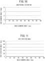
- a relationship of longitudinal distortion (indicated with a sub-scanning angle) relative to the main scanning angle ⁇ in this case is shown in Fig. 10
- a relationship of a spot rotation angle relative to the main scanning angle ⁇ is shown in Fig. 11 .
- a spot light with a cross section shape orthogonal to a proceeding direction which is longer in the sub-scanning direction is projected with parallel movement to an object, whereby it becomes possible to scan ideally.
- a light flux can be irradiated to a measuring object which exists at any place of a scanning surface.
- spot lights SL arranged side by side in the sub-scanning direction are made to come in contact with each other or superimposed on each other. With this, the measurement can be performed without omission in the sub-scanning direction.
- the sub-scanning angle of a measurement range may not be 0 degree, or an incident angle and a sub-scanning angle may not coincide with each other. Furthermore, there are the actual circumstances that since a length in the sub-scanning direction on a cross section orthogonal to the proceeding direction of a spot light is limited, a measuring range where an object exists is required to be divided into the sub-scanning direction.
- a plurality of pairs of the first mirror surface and the second mirror surface are disposed on the mirror unit MU, and that an angle formed by the first mirror surface and the second mirror surface is shifted from 90 degrees for each pair such that light fluxes passing the respective mirror pairs are shifted separately in the sub-scanning angle direction so as to scan on the respective different positions in the sub-scanning angle direction.
- the term "in the case where a virtual plane is set on a range including an object, a light flux emitted from the second mirror surface has, at the time of entering the virtual plane, a cross sectional shape in which a length in the sub-scanning direction orthogonal to the main scanning direction is longer than a length in the main scanning direction”, means as follows.
- a length in a cross section of a light flux means a length at the intensity of the light flux which becomes a half-value width or 1/e2 relative to a light amount of a peak intensity in the light flux. It is noted that the claimed invention is only defined by the appended claims. Furthermore, it may be permissible that light fluxes from a plurality of light sources are superimposed on each other at the respective end portions such that a length in the sub-scanning direction orthogonal to the main scanning direction is made longer apparently.
- the semiconductor laser LD and the collimator lens CL constitute the light projecting system LPS
- the lens LS and the photo diode PD constitute the light receiving system RPS.
- a light emitting surface LDa of the semiconductor laser LD is shaped in a rectangular shape in which a length B in the direction along the rotation axis RO is made longer than a length A in the direction orthogonal to it.
- the light flux emitted from the light projecting system LPS and reflected by the second mirror surface M2 has a cross sectional shape orthogonal to the proceeding direction in which a length in the sub-scanning direction is made longer than a length in the main scanning direction (refer to Fig. 5 ).
- the approximately square tube-shaped mirror unit MU is made of resin, and is held so as to be rotatable around the rotation axis RO being an axis line.
- On its lower outer periphery four trapezoid-shaped first mirror surfaces M1 are disposed, and so as to oppose them, on its upper outer periphery, four trapezoid-shaped second mirror surfaces M2 are disposed.
- An intersection angle between the first mirror surface M1 and the second mirror M paired vertically in each mirror pair is different from the respective intersection angles of the other mirror pairs.
- each of the first mirror surfaces M1 inclines by an angle of 45 degrees to an orthogonal plane to the rotation axis Ro, and the second mirror surfaces M2 incline toward the opposite sides by the respective angles of 60 degrees in the first mirror pair, 55 degrees in the second mirror pair, 50 degrees in the third mirror pair, and 45 degrees in the fourth mirror pair.
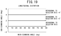
- longitudinal distortion becomes as shown in Fig. 16
- a spot rotation angle becomes as shown in Fig. 17 .
- Each of the first mirror surface M1 and the second mirror surface M2 is covered with a reflective film by depositing, coating, or planting, or a metal polishing mirror or a film mirror by pasting.
- the diverging light fluxes intermittently emitted in a pulse shape from the semiconductor laser LD are converted into parallel light fluxes by the collimator lens CL. Then, the parallel light fluxes are made to enter the first mirror surface M1 of the rotating mirror unit MU, are reflected on there, further reflected by the second mirror surface M2, and are projected so as to scan toward an object (not shown) side.
- Fig. 18 is a cross sectional view showing a modification embodiment of the present embodiment.
- all the respective intersection angles of a plurality of pairs of the first mirror surface M1 and the second mirror surface M2 in the mirror unit MU are constant (90 degrees).
- a light flux LB from the light projecting system LPS is reflected with a reflecting mirror BE used as an example of a deflecting element, reflected by the first mirror surface M1, and then, reflected by the second mirror surface M2.
- the reflecting mirror BE is made rotatable around an axis line PV extending in a direction vertical to a sheet surface.
- the reflecting mirror BE is made to rotate around the axis line PV for each time when each pair of he first mirror surface M1 and the second mirror surface M2 passes, the direction of the light flux LB reflected from the first mirror surface M1 changes, and further, the direction of the light flux LB reflected from the second mirror surface M2 changes in the sub-scanning angle direction. Accordingly, similarly to the above-mentioned embodiment, there is an effect capable of performing scanning in the sub-scanning direction. Fig.
Landscapes
- Physics & Mathematics (AREA)
- General Physics & Mathematics (AREA)
- Optics & Photonics (AREA)
- Engineering & Computer Science (AREA)
- Computer Networks & Wireless Communication (AREA)
- Radar, Positioning & Navigation (AREA)
- Remote Sensing (AREA)
- Optical Radar Systems And Details Thereof (AREA)
- Mechanical Optical Scanning Systems (AREA)
Claims (5)
- Ein optisches Abtastsystem, das zur Verwendung in einer Lichtprojektions- und -empfangsvorrichtung geeignet ist, die zur Detektion von Objekten geeignet ist, wobei das optische Abtastsystem ein Laserradarsystem ist, umfassendeine Spiegeleinheit (MU), umfassend eine erste Spiegelfläche (M1) und eine zweite Spiegelfläche (M2), die zueinander geneigt sind, und von denen jede zu einer Rotationsachse (RO) geneigt ist; undein Lichtprojektionssystem (LPS), das mindestens eine Lichtquelle (LD) enthält, um einen Lichtstrom (LB) in Richtung der ersten Spiegelfläche (M1) zu emittieren,wobei der von der Lichtquelle (LD) emittierte Lichtstrom (LB) an der ersten Spiegelfläche (M1) der Spiegeleinheit (MU) reflektiert wird, danach an der zweiten Spiegelfläche (M2) reflektiert wird und dann so projiziert wird, dass er gemäß einer Drehung der Spiegeleinheit (MU) in einer Hauptabtastrichtung auf ein Objekt abtastet, undwobei in einem Fall, in dem eine virtuelle Ebene (VP) in einem das Objekt einschließenden Bereich festgelegt ist, der an der zweiten Spiegelfläche (M2) reflektierte Lichtstrom (LB), der nach dem Eintritt in die virtuelle Ebene (VP) als ein Lichtpunkt (SL) eine Querschnittsform aufweist, bei der eine Länge in einer zur Hauptabtastrichtung orthogonalen Richtung länger ist als eine Länge in der Hauptabtastrichtung,wobei die Spiegeleinheit (MU) eine Vielzahl von Paaren der ersten Spiegelfläche (M1) und der zweiten Spiegelfläche (M2) enthält und ein Schnittwinkel zwischen der ersten Spiegelfläche (M1) und der zweiten Spiegelfläche (M2) in jedem Paar von den jeweiligen Schnittwinkeln der anderen Paare verschieden ist dadurch gekennzeichnet, dass das Laserradarsystem so eingerichtet ist, dass der Lichtstrom (LB) in der virtuellen Ebene (VP) Lichtpunkte (SL) bildet, die in der Nebenabtastrichtung nebeneinander angeordnet sind und dazu gebracht werden, miteinander in Kontakt zu kommen oder sich gegenseitig zu überlagern.
- Das optische Abtastsystem nach Anspruch 1, ferner umfassend:
ein Ablenkelement, das zwischen der Lichtquelle (LD) und der Spiegeleinheit angeordnet ist und eine Ausbreitungsrichtung eines von der Lichtquelle (LD) emittierten Lichtstroms (LB) ändert. - Das in einem der Ansprüche 1 bis 2 beschriebene optische Abtastsystem, wobei die Lichtquelle (LD) eine lichtemittierende Oberfläche aufweist, bei der eine Länge entlang der Rotationsachse länger ist als eine Länge in einer Richtung senkrecht zur Rotationsachse.
- Eine Lichtprojektions- und -empfangsvorrichtung, umfassend:das in einem der Ansprüche 1 bis 3 beschriebene optische Abtastsystem; undein Lichtempfangssystem, das mit einem Lichtempfangselement ausgestattet ist, das einen von einem Objekt reflektierten Lichtstrom (LB) empfängt.
- Die in Anspruch 4 beschriebene Lichtprojektions- und -empfangsvorrichtung, wobei das Lichtempfangssystem den von dem Objekt reflektierten Lichtstrom (LB) durch eine zweite Spiegelfläche (M2) reflektiert, ferner den reflektierten Lichtstrom (LB) durch eine erste Spiegelfläche (M1) reflektiert und danach den reflektierten Lichtstrom (LB) mit dem Lichtempfangselement empfängt.
Applications Claiming Priority (2)
| Application Number | Priority Date | Filing Date | Title |
|---|---|---|---|
| JP2014207854 | 2014-10-09 | ||
| PCT/JP2015/078325 WO2016056544A1 (ja) | 2014-10-09 | 2015-10-06 | 走査光学系及び投受光装置 |
Publications (3)
| Publication Number | Publication Date |
|---|---|
| EP3206074A1 EP3206074A1 (de) | 2017-08-16 |
| EP3206074A4 EP3206074A4 (de) | 2018-03-14 |
| EP3206074B1 true EP3206074B1 (de) | 2024-07-03 |
Family
ID=55653155
Family Applications (1)
| Application Number | Title | Priority Date | Filing Date |
|---|---|---|---|
| EP15849446.8A Active EP3206074B1 (de) | 2014-10-09 | 2015-10-06 | Optisches abtastsystem sowie lichtprojektions- und empfangsvorrichtung |
Country Status (4)
| Country | Link |
|---|---|
| US (1) | US10162171B2 (de) |
| EP (1) | EP3206074B1 (de) |
| JP (1) | JP6618042B2 (de) |
| WO (1) | WO2016056544A1 (de) |
Families Citing this family (8)
| Publication number | Priority date | Publication date | Assignee | Title |
|---|---|---|---|---|
| JPWO2017135224A1 (ja) * | 2016-02-03 | 2018-11-29 | コニカミノルタ株式会社 | 光走査型の対象物検出装置 |
| US10502949B2 (en) * | 2018-04-04 | 2019-12-10 | Irvine Sensors Corp. | Multi-polygon laser scanner comprising pyramidal timing polygon |
| JP2020060408A (ja) * | 2018-10-09 | 2020-04-16 | パイオニア株式会社 | 投光装置及び測距装置 |
| CN112997099A (zh) * | 2018-11-13 | 2021-06-18 | 纽诺有限公司 | 用于车辆盲点检测的光检测与测距 |
| US12055660B2 (en) * | 2020-05-19 | 2024-08-06 | Gm Cruise Holdings Llc | Polygon scanning mirror for lidar beam scanning |
| WO2022043988A1 (en) * | 2020-08-31 | 2022-03-03 | Arc-Y-Tec Ltd. | A multi-directional pattern projector and a hyper-resolution pattern projector |
| CN113960566A (zh) * | 2021-10-15 | 2022-01-21 | 杭州宇树科技有限公司 | 一种3d激光雷达及足式机器人 |
| DE102022213941A1 (de) | 2022-12-19 | 2024-06-20 | Robert Bosch Gesellschaft mit beschränkter Haftung | LIDAR-Sensor zur optischen Erfassung eines Sichtfeldes und Verfahren zum optischen Erfassen eines Sichtfeldes |
Family Cites Families (18)
| Publication number | Priority date | Publication date | Assignee | Title |
|---|---|---|---|---|
| JPS50109737A (de) | 1974-02-04 | 1975-08-29 | ||
| JPS5162964A (ja) | 1974-11-29 | 1976-05-31 | Citizen Watch Co Ltd | Ondohoshosuishohatsushinkairo |
| JPS52154248U (de) * | 1976-05-18 | 1977-11-22 | ||
| JPS5492757A (en) * | 1977-12-27 | 1979-07-23 | Sueda Intern Inc | Optical scanning apparatus |
| JPS63311320A (ja) | 1987-06-15 | 1988-12-20 | Canon Inc | 光走査装置 |
| JPH01315716A (ja) | 1988-06-16 | 1989-12-20 | Fujitsu Ltd | 走査光学系 |
| JP2771593B2 (ja) * | 1989-04-20 | 1998-07-02 | 富士通株式会社 | 光走査装置 |
| US5793491A (en) * | 1992-12-30 | 1998-08-11 | Schwartz Electro-Optics, Inc. | Intelligent vehicle highway system multi-lane sensor and method |
| US6107622A (en) * | 1997-07-08 | 2000-08-22 | Etec Systems, Inc. | Chevron correction and autofocus optics for laser scanner |
| DE202005005448U1 (de) | 2004-04-06 | 2005-07-07 | Endoscan Gmbh | Bilderzeugende Abtastvorrichtung zur Erfassung von Hohlräumen |
| WO2009099480A1 (en) * | 2008-02-05 | 2009-08-13 | Reliant Technologies, Inc. | Optical pattern generators using axicon segments |
| JP2010249966A (ja) * | 2009-04-14 | 2010-11-04 | Hitachi Ltd | 光学エンジン |
| JP5511333B2 (ja) * | 2009-11-30 | 2014-06-04 | 株式会社豊田中央研究所 | 光走査装置、レーザレーダ装置、及び光走査方法 |
| JP2011122999A (ja) * | 2009-12-14 | 2011-06-23 | Denso Wave Inc | 光導波路装置および校正システム |
| JP2014006110A (ja) * | 2012-06-22 | 2014-01-16 | Konica Minolta Inc | レーザレーダ |
| JP2014071028A (ja) * | 2012-09-28 | 2014-04-21 | Denso Wave Inc | レーザレーダ装置 |
| EP2985650B1 (de) * | 2013-04-11 | 2020-03-04 | Konica Minolta, Inc. | Optisches abtastsystem und radar |
| US10288723B2 (en) | 2014-02-13 | 2019-05-14 | Konica Minolta, Inc. | Mirror unit, distance measurement device and laser radar, and mobile body and fixed object having the mirror unit and the distance measurement device or the laser radar |
-
2015
- 2015-10-06 WO PCT/JP2015/078325 patent/WO2016056544A1/ja not_active Ceased
- 2015-10-06 EP EP15849446.8A patent/EP3206074B1/de active Active
- 2015-10-06 US US15/518,200 patent/US10162171B2/en active Active
- 2015-10-06 JP JP2016553112A patent/JP6618042B2/ja active Active
Also Published As
| Publication number | Publication date |
|---|---|
| WO2016056544A1 (ja) | 2016-04-14 |
| EP3206074A1 (de) | 2017-08-16 |
| JP6618042B2 (ja) | 2019-12-11 |
| EP3206074A4 (de) | 2018-03-14 |
| JPWO2016056544A1 (ja) | 2017-07-27 |
| US10162171B2 (en) | 2018-12-25 |
| US20170293138A1 (en) | 2017-10-12 |
Similar Documents
| Publication | Publication Date | Title |
|---|---|---|
| US10782392B2 (en) | Scanning optical system and light projecting and receiving apparatus | |
| EP3206074B1 (de) | Optisches abtastsystem sowie lichtprojektions- und empfangsvorrichtung | |
| US10989794B2 (en) | Scanning optical system and radar | |
| CN108226899B (zh) | 激光雷达及其工作方法 | |
| EP3717937B1 (de) | Optische entwürfe und detektorentwürfe für verbesserte auflösung in lidar-systemen | |
| US9086273B1 (en) | Microrod compression of laser beam in combination with transmit lens | |
| KR102020037B1 (ko) | 하이브리드 라이다 스캐너 | |
| JP2018529102A (ja) | Lidarセンサ | |
| EP2696166A2 (de) | Optische Messvorrichtung und Sonde | |
| US10649071B2 (en) | Scanning optical system and radar | |
| EP3206073B1 (de) | Abtastendes optisches system und radar | |
| WO2017135225A1 (ja) | 光走査型の対象物検出装置 | |
| CN110662980B (zh) | 用于扫描立体角的方法和设备 | |
| KR102038547B1 (ko) | 16채널형 라이다 | |
| JP7785576B2 (ja) | LiDAR装置およびLiDAR装置の制御方法 | |
| WO2017065049A1 (ja) | 光走査型の対象物検出装置 | |
| US11506785B2 (en) | Asymmetric optical sensor device | |
| WO2016059948A1 (ja) | 走査光学装置 | |
| CN220855345U (zh) | 一种光路结构和混合固态激光雷达 | |
| JP6812776B2 (ja) | 測距センサ | |
| JP2022103109A (ja) | 物体検出装置、センシング装置及び移動体 | |
| WO2017126356A1 (ja) | 対象物検出装置 |
Legal Events
| Date | Code | Title | Description |
|---|---|---|---|
| STAA | Information on the status of an ep patent application or granted ep patent |
Free format text: STATUS: THE INTERNATIONAL PUBLICATION HAS BEEN MADE |
|
| PUAI | Public reference made under article 153(3) epc to a published international application that has entered the european phase |
Free format text: ORIGINAL CODE: 0009012 |
|
| STAA | Information on the status of an ep patent application or granted ep patent |
Free format text: STATUS: REQUEST FOR EXAMINATION WAS MADE |
|
| 17P | Request for examination filed |
Effective date: 20170321 |
|
| AK | Designated contracting states |
Kind code of ref document: A1 Designated state(s): AL AT BE BG CH CY CZ DE DK EE ES FI FR GB GR HR HU IE IS IT LI LT LU LV MC MK MT NL NO PL PT RO RS SE SI SK SM TR |
|
| AX | Request for extension of the european patent |
Extension state: BA ME |
|
| DAV | Request for validation of the european patent (deleted) | ||
| DAX | Request for extension of the european patent (deleted) | ||
| A4 | Supplementary search report drawn up and despatched |
Effective date: 20180213 |
|
| RIC1 | Information provided on ipc code assigned before grant |
Ipc: G02B 26/10 20060101AFI20180207BHEP Ipc: G01S 7/481 20060101ALI20180207BHEP Ipc: G01S 17/93 20060101ALI20180207BHEP Ipc: G02B 26/12 20060101ALI20180207BHEP Ipc: G02B 5/09 20060101ALI20180207BHEP |
|
| STAA | Information on the status of an ep patent application or granted ep patent |
Free format text: STATUS: EXAMINATION IS IN PROGRESS |
|
| 17Q | First examination report despatched |
Effective date: 20190506 |
|
| P01 | Opt-out of the competence of the unified patent court (upc) registered |
Effective date: 20230510 |
|
| REG | Reference to a national code |
Ref country code: DE Ref legal event code: R079 Free format text: PREVIOUS MAIN CLASS: G02B0026100000 Ipc: G02B0005090000 Ref document number: 602015089132 Country of ref document: DE |
|
| GRAP | Despatch of communication of intention to grant a patent |
Free format text: ORIGINAL CODE: EPIDOSNIGR1 |
|
| STAA | Information on the status of an ep patent application or granted ep patent |
Free format text: STATUS: GRANT OF PATENT IS INTENDED |
|
| RIC1 | Information provided on ipc code assigned before grant |
Ipc: G02B 26/12 20060101ALI20240206BHEP Ipc: G01S 7/481 20060101ALI20240206BHEP Ipc: G02B 5/09 20060101AFI20240206BHEP |
|
| INTG | Intention to grant announced |
Effective date: 20240222 |
|
| RIN1 | Information on inventor provided before grant (corrected) |
Inventor name: KOGO, SHOJI Inventor name: ISHIKAWA, RYOUTA |
|
| GRAS | Grant fee paid |
Free format text: ORIGINAL CODE: EPIDOSNIGR3 |
|
| GRAA | (expected) grant |
Free format text: ORIGINAL CODE: 0009210 |
|
| STAA | Information on the status of an ep patent application or granted ep patent |
Free format text: STATUS: THE PATENT HAS BEEN GRANTED |
|
| AK | Designated contracting states |
Kind code of ref document: B1 Designated state(s): AL AT BE BG CH CY CZ DE DK EE ES FI FR GB GR HR HU IE IS IT LI LT LU LV MC MK MT NL NO PL PT RO RS SE SI SK SM TR |
|
| REG | Reference to a national code |
Ref country code: CH Ref legal event code: EP |
|
| REG | Reference to a national code |
Ref country code: DE Ref legal event code: R096 Ref document number: 602015089132 Country of ref document: DE |
|
| REG | Reference to a national code |
Ref country code: LT Ref legal event code: MG9D |
|
| REG | Reference to a national code |
Ref country code: NL Ref legal event code: MP Effective date: 20240703 |
|
| PG25 | Lapsed in a contracting state [announced via postgrant information from national office to epo] |
Ref country code: PT Free format text: LAPSE BECAUSE OF FAILURE TO SUBMIT A TRANSLATION OF THE DESCRIPTION OR TO PAY THE FEE WITHIN THE PRESCRIBED TIME-LIMIT Effective date: 20241104 |
|
| REG | Reference to a national code |
Ref country code: AT Ref legal event code: MK05 Ref document number: 1700414 Country of ref document: AT Kind code of ref document: T Effective date: 20240703 |
|
| PG25 | Lapsed in a contracting state [announced via postgrant information from national office to epo] |
Ref country code: NL Free format text: LAPSE BECAUSE OF FAILURE TO SUBMIT A TRANSLATION OF THE DESCRIPTION OR TO PAY THE FEE WITHIN THE PRESCRIBED TIME-LIMIT Effective date: 20240703 |
|
| PG25 | Lapsed in a contracting state [announced via postgrant information from national office to epo] |
Ref country code: PT Free format text: LAPSE BECAUSE OF FAILURE TO SUBMIT A TRANSLATION OF THE DESCRIPTION OR TO PAY THE FEE WITHIN THE PRESCRIBED TIME-LIMIT Effective date: 20241104 Ref country code: NL Free format text: LAPSE BECAUSE OF FAILURE TO SUBMIT A TRANSLATION OF THE DESCRIPTION OR TO PAY THE FEE WITHIN THE PRESCRIBED TIME-LIMIT Effective date: 20240703 |
|
| PG25 | Lapsed in a contracting state [announced via postgrant information from national office to epo] |
Ref country code: NO Free format text: LAPSE BECAUSE OF FAILURE TO SUBMIT A TRANSLATION OF THE DESCRIPTION OR TO PAY THE FEE WITHIN THE PRESCRIBED TIME-LIMIT Effective date: 20241003 |
|
| PG25 | Lapsed in a contracting state [announced via postgrant information from national office to epo] |
Ref country code: PL Free format text: LAPSE BECAUSE OF FAILURE TO SUBMIT A TRANSLATION OF THE DESCRIPTION OR TO PAY THE FEE WITHIN THE PRESCRIBED TIME-LIMIT Effective date: 20240703 Ref country code: FI Free format text: LAPSE BECAUSE OF FAILURE TO SUBMIT A TRANSLATION OF THE DESCRIPTION OR TO PAY THE FEE WITHIN THE PRESCRIBED TIME-LIMIT Effective date: 20240703 Ref country code: GR Free format text: LAPSE BECAUSE OF FAILURE TO SUBMIT A TRANSLATION OF THE DESCRIPTION OR TO PAY THE FEE WITHIN THE PRESCRIBED TIME-LIMIT Effective date: 20241004 |
|
| PG25 | Lapsed in a contracting state [announced via postgrant information from national office to epo] |
Ref country code: BG Free format text: LAPSE BECAUSE OF FAILURE TO SUBMIT A TRANSLATION OF THE DESCRIPTION OR TO PAY THE FEE WITHIN THE PRESCRIBED TIME-LIMIT Effective date: 20240703 |
|
| PG25 | Lapsed in a contracting state [announced via postgrant information from national office to epo] |
Ref country code: LV Free format text: LAPSE BECAUSE OF FAILURE TO SUBMIT A TRANSLATION OF THE DESCRIPTION OR TO PAY THE FEE WITHIN THE PRESCRIBED TIME-LIMIT Effective date: 20240703 |
|
| PG25 | Lapsed in a contracting state [announced via postgrant information from national office to epo] |
Ref country code: IS Free format text: LAPSE BECAUSE OF FAILURE TO SUBMIT A TRANSLATION OF THE DESCRIPTION OR TO PAY THE FEE WITHIN THE PRESCRIBED TIME-LIMIT Effective date: 20241103 Ref country code: AT Free format text: LAPSE BECAUSE OF FAILURE TO SUBMIT A TRANSLATION OF THE DESCRIPTION OR TO PAY THE FEE WITHIN THE PRESCRIBED TIME-LIMIT Effective date: 20240703 |
|
| PG25 | Lapsed in a contracting state [announced via postgrant information from national office to epo] |
Ref country code: CZ Free format text: LAPSE BECAUSE OF FAILURE TO SUBMIT A TRANSLATION OF THE DESCRIPTION OR TO PAY THE FEE WITHIN THE PRESCRIBED TIME-LIMIT Effective date: 20240703 Ref country code: HR Free format text: LAPSE BECAUSE OF FAILURE TO SUBMIT A TRANSLATION OF THE DESCRIPTION OR TO PAY THE FEE WITHIN THE PRESCRIBED TIME-LIMIT Effective date: 20240703 |
|
| PG25 | Lapsed in a contracting state [announced via postgrant information from national office to epo] |
Ref country code: ES Free format text: LAPSE BECAUSE OF FAILURE TO SUBMIT A TRANSLATION OF THE DESCRIPTION OR TO PAY THE FEE WITHIN THE PRESCRIBED TIME-LIMIT Effective date: 20240703 Ref country code: RS Free format text: LAPSE BECAUSE OF FAILURE TO SUBMIT A TRANSLATION OF THE DESCRIPTION OR TO PAY THE FEE WITHIN THE PRESCRIBED TIME-LIMIT Effective date: 20241003 |
|
| PG25 | Lapsed in a contracting state [announced via postgrant information from national office to epo] |
Ref country code: RS Free format text: LAPSE BECAUSE OF FAILURE TO SUBMIT A TRANSLATION OF THE DESCRIPTION OR TO PAY THE FEE WITHIN THE PRESCRIBED TIME-LIMIT Effective date: 20241003 Ref country code: PL Free format text: LAPSE BECAUSE OF FAILURE TO SUBMIT A TRANSLATION OF THE DESCRIPTION OR TO PAY THE FEE WITHIN THE PRESCRIBED TIME-LIMIT Effective date: 20240703 Ref country code: NO Free format text: LAPSE BECAUSE OF FAILURE TO SUBMIT A TRANSLATION OF THE DESCRIPTION OR TO PAY THE FEE WITHIN THE PRESCRIBED TIME-LIMIT Effective date: 20241003 Ref country code: LV Free format text: LAPSE BECAUSE OF FAILURE TO SUBMIT A TRANSLATION OF THE DESCRIPTION OR TO PAY THE FEE WITHIN THE PRESCRIBED TIME-LIMIT Effective date: 20240703 Ref country code: IS Free format text: LAPSE BECAUSE OF FAILURE TO SUBMIT A TRANSLATION OF THE DESCRIPTION OR TO PAY THE FEE WITHIN THE PRESCRIBED TIME-LIMIT Effective date: 20241103 Ref country code: HR Free format text: LAPSE BECAUSE OF FAILURE TO SUBMIT A TRANSLATION OF THE DESCRIPTION OR TO PAY THE FEE WITHIN THE PRESCRIBED TIME-LIMIT Effective date: 20240703 Ref country code: GR Free format text: LAPSE BECAUSE OF FAILURE TO SUBMIT A TRANSLATION OF THE DESCRIPTION OR TO PAY THE FEE WITHIN THE PRESCRIBED TIME-LIMIT Effective date: 20241004 Ref country code: FI Free format text: LAPSE BECAUSE OF FAILURE TO SUBMIT A TRANSLATION OF THE DESCRIPTION OR TO PAY THE FEE WITHIN THE PRESCRIBED TIME-LIMIT Effective date: 20240703 Ref country code: ES Free format text: LAPSE BECAUSE OF FAILURE TO SUBMIT A TRANSLATION OF THE DESCRIPTION OR TO PAY THE FEE WITHIN THE PRESCRIBED TIME-LIMIT Effective date: 20240703 Ref country code: CZ Free format text: LAPSE BECAUSE OF FAILURE TO SUBMIT A TRANSLATION OF THE DESCRIPTION OR TO PAY THE FEE WITHIN THE PRESCRIBED TIME-LIMIT Effective date: 20240703 Ref country code: BG Free format text: LAPSE BECAUSE OF FAILURE TO SUBMIT A TRANSLATION OF THE DESCRIPTION OR TO PAY THE FEE WITHIN THE PRESCRIBED TIME-LIMIT Effective date: 20240703 Ref country code: AT Free format text: LAPSE BECAUSE OF FAILURE TO SUBMIT A TRANSLATION OF THE DESCRIPTION OR TO PAY THE FEE WITHIN THE PRESCRIBED TIME-LIMIT Effective date: 20240703 |
|
| REG | Reference to a national code |
Ref country code: DE Ref legal event code: R097 Ref document number: 602015089132 Country of ref document: DE |
|
| PG25 | Lapsed in a contracting state [announced via postgrant information from national office to epo] |
Ref country code: SM Free format text: LAPSE BECAUSE OF FAILURE TO SUBMIT A TRANSLATION OF THE DESCRIPTION OR TO PAY THE FEE WITHIN THE PRESCRIBED TIME-LIMIT Effective date: 20240703 Ref country code: DK Free format text: LAPSE BECAUSE OF FAILURE TO SUBMIT A TRANSLATION OF THE DESCRIPTION OR TO PAY THE FEE WITHIN THE PRESCRIBED TIME-LIMIT Effective date: 20240703 Ref country code: RO Free format text: LAPSE BECAUSE OF FAILURE TO SUBMIT A TRANSLATION OF THE DESCRIPTION OR TO PAY THE FEE WITHIN THE PRESCRIBED TIME-LIMIT Effective date: 20240703 |
|
| PG25 | Lapsed in a contracting state [announced via postgrant information from national office to epo] |
Ref country code: EE Free format text: LAPSE BECAUSE OF FAILURE TO SUBMIT A TRANSLATION OF THE DESCRIPTION OR TO PAY THE FEE WITHIN THE PRESCRIBED TIME-LIMIT Effective date: 20240703 |
|
| PG25 | Lapsed in a contracting state [announced via postgrant information from national office to epo] |
Ref country code: IT Free format text: LAPSE BECAUSE OF FAILURE TO SUBMIT A TRANSLATION OF THE DESCRIPTION OR TO PAY THE FEE WITHIN THE PRESCRIBED TIME-LIMIT Effective date: 20240703 Ref country code: SK Free format text: LAPSE BECAUSE OF FAILURE TO SUBMIT A TRANSLATION OF THE DESCRIPTION OR TO PAY THE FEE WITHIN THE PRESCRIBED TIME-LIMIT Effective date: 20240703 |
|
| PLBE | No opposition filed within time limit |
Free format text: ORIGINAL CODE: 0009261 |
|
| STAA | Information on the status of an ep patent application or granted ep patent |
Free format text: STATUS: NO OPPOSITION FILED WITHIN TIME LIMIT |
|
| REG | Reference to a national code |
Ref country code: CH Ref legal event code: PL |
|
| 26N | No opposition filed |
Effective date: 20250404 |
|
| PG25 | Lapsed in a contracting state [announced via postgrant information from national office to epo] |
Ref country code: MC Free format text: LAPSE BECAUSE OF FAILURE TO SUBMIT A TRANSLATION OF THE DESCRIPTION OR TO PAY THE FEE WITHIN THE PRESCRIBED TIME-LIMIT Effective date: 20240703 |
|
| PG25 | Lapsed in a contracting state [announced via postgrant information from national office to epo] |
Ref country code: LU Free format text: LAPSE BECAUSE OF NON-PAYMENT OF DUE FEES Effective date: 20241006 Ref country code: BE Free format text: LAPSE BECAUSE OF NON-PAYMENT OF DUE FEES Effective date: 20241031 |
|
| PG25 | Lapsed in a contracting state [announced via postgrant information from national office to epo] |
Ref country code: CH Free format text: LAPSE BECAUSE OF NON-PAYMENT OF DUE FEES Effective date: 20241031 |
|
| REG | Reference to a national code |
Ref country code: BE Ref legal event code: MM Effective date: 20241031 |
|
| PG25 | Lapsed in a contracting state [announced via postgrant information from national office to epo] |
Ref country code: SE Free format text: LAPSE BECAUSE OF FAILURE TO SUBMIT A TRANSLATION OF THE DESCRIPTION OR TO PAY THE FEE WITHIN THE PRESCRIBED TIME-LIMIT Effective date: 20240703 |
|
| PGFP | Annual fee paid to national office [announced via postgrant information from national office to epo] |
Ref country code: GB Payment date: 20250904 Year of fee payment: 11 |
|
| PGFP | Annual fee paid to national office [announced via postgrant information from national office to epo] |
Ref country code: FR Payment date: 20250908 Year of fee payment: 11 |
|
| PG25 | Lapsed in a contracting state [announced via postgrant information from national office to epo] |
Ref country code: IE Free format text: LAPSE BECAUSE OF NON-PAYMENT OF DUE FEES Effective date: 20241006 |
|
| PGFP | Annual fee paid to national office [announced via postgrant information from national office to epo] |
Ref country code: DE Payment date: 20250902 Year of fee payment: 11 |
|
| PG25 | Lapsed in a contracting state [announced via postgrant information from national office to epo] |
Ref country code: CY Free format text: LAPSE BECAUSE OF FAILURE TO SUBMIT A TRANSLATION OF THE DESCRIPTION OR TO PAY THE FEE WITHIN THE PRESCRIBED TIME-LIMIT; INVALID AB INITIO Effective date: 20151006 |
|
| PG25 | Lapsed in a contracting state [announced via postgrant information from national office to epo] |
Ref country code: HU Free format text: LAPSE BECAUSE OF FAILURE TO SUBMIT A TRANSLATION OF THE DESCRIPTION OR TO PAY THE FEE WITHIN THE PRESCRIBED TIME-LIMIT; INVALID AB INITIO Effective date: 20151006 |