EP3206220A1 - Flugzeitmassenspektrometer mit verbessertem raumfokus - Google Patents
Flugzeitmassenspektrometer mit verbessertem raumfokus Download PDFInfo
- Publication number
- EP3206220A1 EP3206220A1 EP17164277.0A EP17164277A EP3206220A1 EP 3206220 A1 EP3206220 A1 EP 3206220A1 EP 17164277 A EP17164277 A EP 17164277A EP 3206220 A1 EP3206220 A1 EP 3206220A1
- Authority
- EP
- European Patent Office
- Prior art keywords
- stage
- mass spectrometer
- time
- deceleration
- acceleration
- Prior art date
- Legal status (The legal status is an assumption and is not a legal conclusion. Google has not performed a legal analysis and makes no representation as to the accuracy of the status listed.)
- Withdrawn
Links
Images






Classifications
-
- H—ELECTRICITY
- H01—ELECTRIC ELEMENTS
- H01J—ELECTRIC DISCHARGE TUBES OR DISCHARGE LAMPS
- H01J49/00—Particle spectrometers or separator tubes
- H01J49/26—Mass spectrometers or separator tubes
- H01J49/34—Dynamic spectrometers
- H01J49/40—Time-of-flight spectrometers
-
- H—ELECTRICITY
- H01—ELECTRIC ELEMENTS
- H01J—ELECTRIC DISCHARGE TUBES OR DISCHARGE LAMPS
- H01J49/00—Particle spectrometers or separator tubes
- H01J49/26—Mass spectrometers or separator tubes
- H01J49/34—Dynamic spectrometers
- H01J49/40—Time-of-flight spectrometers
- H01J49/403—Time-of-flight spectrometers characterised by the acceleration optics and/or the extraction fields
-
- H—ELECTRICITY
- H01—ELECTRIC ELEMENTS
- H01J—ELECTRIC DISCHARGE TUBES OR DISCHARGE LAMPS
- H01J49/00—Particle spectrometers or separator tubes
- H01J49/0027—Methods for using particle spectrometers
-
- H—ELECTRICITY
- H01—ELECTRIC ELEMENTS
- H01J—ELECTRIC DISCHARGE TUBES OR DISCHARGE LAMPS
- H01J49/00—Particle spectrometers or separator tubes
- H01J49/02—Details
- H01J49/06—Electron- or ion-optical arrangements
-
- H—ELECTRICITY
- H01—ELECTRIC ELEMENTS
- H01J—ELECTRIC DISCHARGE TUBES OR DISCHARGE LAMPS
- H01J49/00—Particle spectrometers or separator tubes
- H01J49/26—Mass spectrometers or separator tubes
- H01J49/34—Dynamic spectrometers
- H01J49/40—Time-of-flight spectrometers
- H01J49/401—Time-of-flight spectrometers characterised by orthogonal acceleration, e.g. focusing or selecting the ions, pusher electrode
Definitions
- the present invention relates to a mass spectrometer and a method of mass spectrometry.
- Wiley and McLaren (Time-of-Flight Mass Spectrometer with Improved Resolution, (Review of Scientific Instruments 26, 1150 (1955), WC Wiley, IH McLar en) set out the basic equations that describe two stage extraction Time of Flight mass spectrometers.
- the principles apply equally to continuous axial extraction Time of Flight mass analysers and orthogonal acceleration Time of Flight mass analysers and time lag focussing instruments.
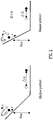
- Fig. 1 shows the principle of second order spatial (or space) focussing wherein ions with an initial spatial distribution are brought to a focus at the plane of an ion detector thereby improving instrumental resolution.
- a known solution to this problem is to add a reflectron wherein the first position of spatial focus is re-imaged at the ion detector as shown in Fig. 4 . This leads to longer practical flight time instruments which are capable of relatively high resolution.
- the reflectron may comprise either a single stage reflectron or a two stage reflectron whilst in both reflectron and non-reflectron Time of Flight instruments the extraction region usually comprises a two stage Wiley/McLaren source.
- the objective is to achieve perfect first or second order space focusing or to re-introduce a small first order term to further improve space focusing.
- a mass spectrometer comprising:
- a fifth order spatial focusing term is introduced which preferably offsets the effects of a non-zero third order spatial focusing term.
- the spread of ion arrival times at the ion detector is significantly reduced according to the preferred embodiment which improves the resolution of the mass spectrometer.
- a mass spectrometer comprising:
- a fourth order spatial focusing term is introduced which preferably offsets the effects of a non-zero second order spatial focusing term.
- the spread of ion arrival times at the ion detector is significantly reduced according to the preferred embodiment which improves the resolution of the mass spectrometer.
- the source region preferably comprises an extraction stage and a first acceleration stage and wherein the fourth order spatial focusing device and/or the fifth order spatial focusing device preferably comprise a third stage in the source region, the third stage comprising either: (i) a second acceleration stage; (ii) a deceleration stage; or (iii) a field free region.
- the third stage in the source region is preferably pulsed, in use, in synchronism with the extraction stage.
- the Time of Flight mass analyser preferably further comprises a reflectron having a first deceleration or acceleration stage and a second deceleration or acceleration stage.
- the fourth order spatial focusing device and/or the fifth order spatial focusing device preferably comprise a third deceleration or acceleration stage provided within the reflectron.
- a first electric field gradient E1 is maintained across the first deceleration or acceleration stage
- a second electric field gradient E2 is maintained across the second deceleration or acceleration stage
- a third electric field gradient E3 is maintained across the third deceleration or acceleration stage.
- the reflectron preferably comprises a multi-pass reflectron i.e. ions are reflected back in a direction towards the ion detector more than once. According to an embodiment the ions follow a W-shaped path through the drift region from the source region to the ion detector.
- the Time of Flight mass analyser preferably further comprises a drift region intermediate the source region and the reflectron, wherein the fourth order spatial focusing device and/or the fifth order spatial focusing device preferably comprise a deceleration or acceleration stage provided in the drift region.
- the mass spectrometer preferably further comprises a device arranged and adapted to introduce a first order spatial focusing term to compensate for ions having an initial spread of velocities.
- the mass spectrometer preferably further comprises a device arranged and adapted to introduce a first order spatial focusing term to improve spatial focussing.
- the mass spectrometer preferably further comprises a beam expander arranged upstream of the source region, the beam expander being arranged and adapted to reduce an initial spread of velocities of ions arriving in the source region.
- the fourth order spatial focusing device and/or the fifth order spatial focusing device are preferably arranged and adapted so that the spread of ion arrival times ⁇ T in nanoseconds as a function of the initial spread of positions ⁇ x in millimetres is selected from the group consisting of: (i) ⁇ 0.1 ns; (ii) ⁇ 0.9 ns; (iii) ⁇ 0.8 ns; (iv) ⁇ 0.7 ns; (v) ⁇ 0.6 ns; (vi) ⁇ 0.5 ns; (vii) ⁇ 0.4 ns; (viii) ⁇ 0.3 ns; (ix) ⁇ 0.2 ns; (x) ⁇ 0.1 ns.
- the Time of Flight mass analyser preferably comprises a linear Time of Flight mass analyser or an orthogonal acceleration Time of Flight mass analyser.
- the Time of Flight mass analyser preferably comprises a multi-pass Time of Flight mass analyser.
- a method of mass spectrometry comprising:
- a method of mass spectrometry comprising:
- the preferred embodiment is concerned with the deterministic introduction of higher order space focusing aberrations which aid the ultimate space focusing achieved resulting in improved resolution and/or sensitivity.
- the mass spectrometer preferably further comprises an ion source selected from the group consisting of: (i) an Electrospray ionisation (“ESI”) ion source; (ii) an Atmospheric Pressure Photo Ionisation (“APPI”) ion source; (iii) an Atmospheric Pressure Chemical Ionisation (“APCI”) ion source; (iv) a Matrix Assisted Laser Desorption Ionisation (“MALDI”) ion source; (v) a Laser Desorption Ionisation (“LDI”) ion source; (vi) an Atmospheric Pressure Ionisation (“API”) ion source; (vii) a Desorption Ionisation on Silicon (“DIOS”) ion source; (viii) an Electron Impact (“EI”) ion source; (ix) a Chemical Ionisation ("CI”) ion source; (x) a Field Ionisation (“FI”) ion source; (xi) a Field Desorption (“FD”) ion source; (x
- the mass spectrometer preferably further comprises one or more collision, fragmentation or reaction cells selected from the group consisting of: (i) a Collisional Induced Dissociation (“CID”) fragmentation device; (ii) a Surface Induced Dissociation (“SID”) fragmentation device; (iii) an Electron Transfer Dissociation (“ETD”) fragmentation device; (iv) an Electron Capture Dissociation (“ECD”) fragmentation device; (v) an Electron Collision or Impact Dissociation fragmentation device; (vi) a Photo Induced Dissociation (“PID”) fragmentation device; (vii) a Laser Induced Dissociation fragmentation device; (viii) an infrared radiation induced dissociation device; (ix) an ultraviolet radiation induced dissociation device; (x) a nozzle-skimmer interface fragmentation device; (xi) an in-source fragmentation device; (xii) an in-source Collision Induced Dissociation fragmentation device; (xiii) a thermal
- the mass spectrometer may further comprise a stacked ring ion guide comprising a plurality of electrodes having an aperture through which ions are transmitted in use and wherein the spacing of the electrodes increases along the length of the ion path.
- the apertures in the electrodes in an upstream section of the ion guide may have a first diameter and the apertures in the electrodes in a downstream section of the ion guide may have a second diameter which is smaller than the first diameter.
- Opposite phases of an AC or RF voltage are preferably applied to successive electrodes.
- mv is the momentum of the ion beam and the region length Lp is inherently related linearly to the extent of the beam in the pusher.
- a fundamental theorem in ion optics is "Liouville's theorem” which states that: “For a cloud of moving particles, the particle density p(x, p x , y, p y , z, p z ) in phase space is invariable” (Geometrical Charged-Particle Optics, Harald H. Rose, Springer Series in Optical Sciences 142) where p x , p y and p z are the momenta of the three Cartesian coordinate directions.
- a cloud of particles at a time t 1 that fills a certain volume in phase space may change its shape at a later time t n but not the magnitude of its volume. Attempts to reduce this volume by the use of electromagnetic fields will be futile although it is possible to sample desired regions of phase space by aperturing the beam (rejecting unfocusable ions) before subsequent manipulation.
- a first order approximation splits Liouville's theorem into the three independent space coordinates x, y and z.
- the ion beam can now be described in terms of three independent phase space areas the shape of which change as the ion beam progresses through an ion optical system but not the total area itself.
- Fig. 5 shows an optical system comprising N optical elements with each element changing the shape of the phase space but not its area.
- Conservation of phase space means that the ⁇ x p x term will be constant and so expanding the beam will lead to lower velocity spreads. This is because the ⁇ x p x is proportional to the Lp*mv term in Eqn. 4. These lower velocity spreads can ultimately lead to a proportionally lower turnaround times for a fixed extraction field.
- an orthogonal acceleration Time of Flight mass spectrometer with the ability to spatially focus larger positional spreads ⁇ x will result in a reduced turnaround time and hence higher resolution if the beam is further expanded prior to the extraction region and the field in the extraction region remains constant.
- the aperture size can be increased resulting in improved transmission and sensitivity for the same resolution if the beam undergoes no further expansion.
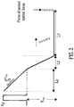
- Fig. 6A shows a conventional Time of Flight geometry comprising a two stage Wiley/McLaren source, an intermediate field free region and a two stage reflectron.
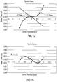
- FIG. 7A and 7B A typical space focusing approach for conventional Time of Flight mass analyser as shown in Fig. 6A is illustrated in Figs. 7A and 7B .
- the geometry is configured to provide second order focusing together with an opposing first order term as illustrated in Fig. 7A .
- the resulting residuals have a lower absolute time spread than either the third order or first order terms individually ( Fig. 7B ).
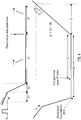
- Fig. 6B shows a preferred embodiment of the present invention wherein the known two stage Wiley/McLaren source has been replaced by a three stage source.
- the first stage of the source has the same extraction field as the extraction region of the known two stage Wiley/McLaren source as shown in Fig. 6A .
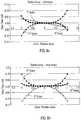
- the geometry is preferably configured to introduce higher order space focusing terms. These higher order space focusing terms are preferably arranged such that the odd powers (see Fig. 8A ) combine to minimise the overall residuals and also so that even powers (see Fig. 8B ) will also combine to minimise the overall residuals.
- the combined residuals are plotted in Fig. 8C on the same scale as Fig. 7B and illustrate how according to the preferred embodiment substantially improved space focusing may be obtained.
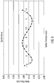
- the improved space focus according to the preferred embodiment and as illustrated by Fig. 8C allows expansion of the beam as shown in Fig. 9 .
- the ion beam width is scaled by a factor of 1.5 when compared with Fig. 7B yet the absolute time spreads are comparable.
- the ions in the wider beam have a reduced spread of velocities which enables the spread in ion arrival times at the ion detector to be reduced thereby improving resolution.
- FIG. 10 A simulation was performed which compared the two different geometries shown in Figs. 6A and Fig. 6B .
- the improvement in resolution according to the preferred embodiment is illustrated in Fig. 10 .
- the dashed line peak shown in Fig. 10 shows the enhanced resolution obtained according to the preferred embodiment and corresponds to the preferred three stage source which receives a x1.5 wider ion beam having a proportionally lower velocity spread.
- the resolution enhancement is compared with that obtained conventional as represented by the solid line peak.
- the vertical scale is normalised for comparison purposes but in reality the area of the two peaks is the same.
- the initial conditions of an ion beam in the simulation were defined by a stacked ring RF ion guide ("SRIG") in the presence of a buffer gas.
- SRIG stacked ring RF ion guide
- the ions typically adopt a Maxwellian distribution of velocities on exit from the RF element due to the thermal motion of gas molecules with a beam cross section of 1-2 mm.
- Simulations of the velocity spreads were performed using SIMION (RTM) and a hard sphere model.
- the hard sphere model simulated collisions with residual gas molecules in the stacked ring RF ion guide. These ion conditions were then used as the input beam parameters for the different geometry types.
- pre-extraction phase space so as to include non linear (>1 st order) odd power terms as shown in Fig. 11 .
- These higher order terms can be used to compensate for the higher order odd powered space focus terms further reducing the absolute time spread.
- the preferred embodiment relates to providing a third or further stage in the source region of the Time of Flight mass analyser
- an additional acceleration or deceleration region may be provided within the intermediate field free region between the source and the reflectron.
- an additional acceleration, deceleration or field free region may be provided with the reflectron.
- one or more additional regions are provided within the source and/or field free region and/or reflectron.
- the preferred embodiment is primarily concerned with a device arranged and adapted to introduce a fourth and/or fifth order spatial focusing term
- further embodiments are contemplated wherein a sixth and/or seventh and/or eighth and/or ninth and/or higher order spatial focusing term may be introduced.
Landscapes
- Chemical & Material Sciences (AREA)
- Analytical Chemistry (AREA)
- Physics & Mathematics (AREA)
- Optics & Photonics (AREA)
- Other Investigation Or Analysis Of Materials By Electrical Means (AREA)
Applications Claiming Priority (3)
| Application Number | Priority Date | Filing Date | Title |
|---|---|---|---|
| GBGB1021840.2A GB201021840D0 (en) | 2010-12-23 | 2010-12-23 | Improved space focus time of flight mass spectrometer |
| US201161432837P | 2011-01-14 | 2011-01-14 | |
| EP11804773.7A EP2656376B1 (de) | 2010-12-23 | 2011-12-22 | Flugzeitmassenspektrometer mit verbessertem raumfokus |
Related Parent Applications (1)
| Application Number | Title | Priority Date | Filing Date |
|---|---|---|---|
| EP11804773.7A Division EP2656376B1 (de) | 2010-12-23 | 2011-12-22 | Flugzeitmassenspektrometer mit verbessertem raumfokus |
Publications (1)
| Publication Number | Publication Date |
|---|---|
| EP3206220A1 true EP3206220A1 (de) | 2017-08-16 |
Family
ID=43598891
Family Applications (2)
| Application Number | Title | Priority Date | Filing Date |
|---|---|---|---|
| EP11804773.7A Active EP2656376B1 (de) | 2010-12-23 | 2011-12-22 | Flugzeitmassenspektrometer mit verbessertem raumfokus |
| EP17164277.0A Withdrawn EP3206220A1 (de) | 2010-12-23 | 2011-12-22 | Flugzeitmassenspektrometer mit verbessertem raumfokus |
Family Applications Before (1)
| Application Number | Title | Priority Date | Filing Date |
|---|---|---|---|
| EP11804773.7A Active EP2656376B1 (de) | 2010-12-23 | 2011-12-22 | Flugzeitmassenspektrometer mit verbessertem raumfokus |
Country Status (6)
| Country | Link |
|---|---|
| US (3) | US9214328B2 (de) |
| EP (2) | EP2656376B1 (de) |
| JP (1) | JP5914515B2 (de) |
| CA (2) | CA3210803A1 (de) |
| GB (2) | GB201021840D0 (de) |
| WO (1) | WO2012085594A2 (de) |
Families Citing this family (21)
| Publication number | Priority date | Publication date | Assignee | Title |
|---|---|---|---|---|
| GB201021840D0 (en) * | 2010-12-23 | 2011-02-02 | Micromass Ltd | Improved space focus time of flight mass spectrometer |
| CA2932378A1 (en) * | 2013-12-24 | 2015-07-02 | Dh Technologies Development Pte. Ltd. | High speed polarity switch time-of-flight spectrometer |
| JP6287410B2 (ja) * | 2014-03-19 | 2018-03-07 | 株式会社島津製作所 | 飛行時間型質量分析装置 |
| DE102014115034B4 (de) * | 2014-10-16 | 2017-06-08 | Bruker Daltonik Gmbh | Flugzeitmassenspektrometer mit räumlicher Fokussierung eines breiten Massenbereichs |
| GB201613988D0 (en) | 2016-08-16 | 2016-09-28 | Micromass Uk Ltd And Leco Corp | Mass analyser having extended flight path |
| GB2567794B (en) | 2017-05-05 | 2023-03-08 | Micromass Ltd | Multi-reflecting time-of-flight mass spectrometers |
| GB2563571B (en) | 2017-05-26 | 2023-05-24 | Micromass Ltd | Time of flight mass analyser with spatial focussing |
| US11295944B2 (en) | 2017-08-06 | 2022-04-05 | Micromass Uk Limited | Printed circuit ion mirror with compensation |
| US11081332B2 (en) | 2017-08-06 | 2021-08-03 | Micromass Uk Limited | Ion guide within pulsed converters |
| US11211238B2 (en) | 2017-08-06 | 2021-12-28 | Micromass Uk Limited | Multi-pass mass spectrometer |
| US11817303B2 (en) | 2017-08-06 | 2023-11-14 | Micromass Uk Limited | Accelerator for multi-pass mass spectrometers |
| EP3662503A1 (de) | 2017-08-06 | 2020-06-10 | Micromass UK Limited | Ioneninjektion in ein massenspektrometer mit mehreren durchgängen |
| EP3662501A1 (de) | 2017-08-06 | 2020-06-10 | Micromass UK Limited | Ionenspiegel für multireflektierendes massenspektrometer |
| WO2019030473A1 (en) | 2017-08-06 | 2019-02-14 | Anatoly Verenchikov | FIELDS FOR SMART REFLECTIVE TOF SM |
| GB201806507D0 (en) | 2018-04-20 | 2018-06-06 | Verenchikov Anatoly | Gridless ion mirrors with smooth fields |
| GB201807605D0 (en) | 2018-05-10 | 2018-06-27 | Micromass Ltd | Multi-reflecting time of flight mass analyser |
| GB201807626D0 (en) | 2018-05-10 | 2018-06-27 | Micromass Ltd | Multi-reflecting time of flight mass analyser |
| GB201808530D0 (en) | 2018-05-24 | 2018-07-11 | Verenchikov Anatoly | TOF MS detection system with improved dynamic range |
| GB201810573D0 (en) | 2018-06-28 | 2018-08-15 | Verenchikov Anatoly | Multi-pass mass spectrometer with improved duty cycle |
| GB201901411D0 (en) | 2019-02-01 | 2019-03-20 | Micromass Ltd | Electrode assembly for mass spectrometer |
| GB201903779D0 (en) | 2019-03-20 | 2019-05-01 | Micromass Ltd | Multiplexed time of flight mass spectrometer |
Citations (7)
| Publication number | Priority date | Publication date | Assignee | Title |
|---|---|---|---|---|
| US5464985A (en) * | 1993-10-01 | 1995-11-07 | The Johns Hopkins University | Non-linear field reflectron |
| US5869829A (en) * | 1996-07-03 | 1999-02-09 | Analytica Of Branford, Inc. | Time-of-flight mass spectrometer with first and second order longitudinal focusing |
| US6013913A (en) * | 1998-02-06 | 2000-01-11 | The University Of Northern Iowa | Multi-pass reflectron time-of-flight mass spectrometer |
| US6627877B1 (en) * | 1997-03-12 | 2003-09-30 | Gbc Scientific Equipment Pty Ltd. | Time of flight analysis device |
| US20040084613A1 (en) * | 2001-04-03 | 2004-05-06 | Bateman Robert Harold | Mass spectrometer and method of mass spectrometry |
| US20040232327A1 (en) * | 2003-03-11 | 2004-11-25 | Bateman Robert Harold | Mass spectrometer |
| US20060255294A1 (en) * | 2005-05-13 | 2006-11-16 | Martin Roy E Iii | Ion optical mounting assemblies |
Family Cites Families (12)
| Publication number | Priority date | Publication date | Assignee | Title |
|---|---|---|---|---|
| US113101A (en) * | 1871-03-28 | Improvement in cut-off attachments to slide-valves | ||
| US5814813A (en) * | 1996-07-08 | 1998-09-29 | The Johns Hopkins University | End cap reflection for a time-of-flight mass spectrometer and method of using the same |
| GB9802115D0 (en) * | 1998-01-30 | 1998-04-01 | Shimadzu Res Lab Europe Ltd | Time-of-flight mass spectrometer |
| WO2000076638A1 (en) * | 1999-06-11 | 2000-12-21 | The Johns Hopkins University | Method and apparatus of mass-correlated pulsed extraction for a time-of-flight mass spectrometer |
| JP2002245964A (ja) * | 2001-02-22 | 2002-08-30 | Jeol Ltd | 飛行時間型質量分析装置 |
| GB2390935A (en) * | 2002-07-16 | 2004-01-21 | Anatoli Nicolai Verentchikov | Time-nested mass analysis using a TOF-TOF tandem mass spectrometer |
| GB2403063A (en) * | 2003-06-21 | 2004-12-22 | Anatoli Nicolai Verentchikov | Time of flight mass spectrometer employing a plurality of lenses focussing an ion beam in shift direction |
| US7385187B2 (en) | 2003-06-21 | 2008-06-10 | Leco Corporation | Multi-reflecting time-of-flight mass spectrometer and method of use |
| JP5357538B2 (ja) | 2005-03-22 | 2013-12-04 | レコ コーポレイション | 等時性湾曲イオンインタフェースを備えた多重反射型飛行時間質量分析計 |
| US7667195B2 (en) | 2007-05-01 | 2010-02-23 | Virgin Instruments Corporation | High performance low cost MALDI MS-MS |
| EP2595174B8 (de) * | 2010-06-08 | 2019-01-16 | Micromass UK Limited | Massenspektrometer mit zwei Flugzeitanalysatoren für Analyse von positiven und negativen Ionen. |
| GB201021840D0 (en) * | 2010-12-23 | 2011-02-02 | Micromass Ltd | Improved space focus time of flight mass spectrometer |
-
2010
- 2010-12-23 GB GBGB1021840.2A patent/GB201021840D0/en not_active Ceased
-
2011
- 2011-12-22 CA CA3210803A patent/CA3210803A1/en active Pending
- 2011-12-22 EP EP11804773.7A patent/EP2656376B1/de active Active
- 2011-12-22 JP JP2013545509A patent/JP5914515B2/ja active Active
- 2011-12-22 EP EP17164277.0A patent/EP3206220A1/de not_active Withdrawn
- 2011-12-22 GB GB1122208.0A patent/GB2486819B/en active Active
- 2011-12-22 CA CA2822407A patent/CA2822407C/en active Active
- 2011-12-22 WO PCT/GB2011/052576 patent/WO2012085594A2/en not_active Ceased
- 2011-12-22 US US13/996,893 patent/US9214328B2/en active Active
-
2015
- 2015-12-14 US US14/968,171 patent/US10553418B2/en active Active
-
2020
- 2020-01-30 US US16/777,099 patent/US20200243321A1/en not_active Abandoned
Patent Citations (7)
| Publication number | Priority date | Publication date | Assignee | Title |
|---|---|---|---|---|
| US5464985A (en) * | 1993-10-01 | 1995-11-07 | The Johns Hopkins University | Non-linear field reflectron |
| US5869829A (en) * | 1996-07-03 | 1999-02-09 | Analytica Of Branford, Inc. | Time-of-flight mass spectrometer with first and second order longitudinal focusing |
| US6627877B1 (en) * | 1997-03-12 | 2003-09-30 | Gbc Scientific Equipment Pty Ltd. | Time of flight analysis device |
| US6013913A (en) * | 1998-02-06 | 2000-01-11 | The University Of Northern Iowa | Multi-pass reflectron time-of-flight mass spectrometer |
| US20040084613A1 (en) * | 2001-04-03 | 2004-05-06 | Bateman Robert Harold | Mass spectrometer and method of mass spectrometry |
| US20040232327A1 (en) * | 2003-03-11 | 2004-11-25 | Bateman Robert Harold | Mass spectrometer |
| US20060255294A1 (en) * | 2005-05-13 | 2006-11-16 | Martin Roy E Iii | Ion optical mounting assemblies |
Non-Patent Citations (3)
| Title |
|---|
| BOESL U ET AL: "Reflectron time-of-flight mass spectrometry and laser excitation for the analysis of neutrals, ionized molecules and secondary fragments", INTERNATIONAL JOURNAL OF MASS SPECTROMETRY AND ION PROCESSES, ELSEVIER SCIENTIFIC PUBLISHING CO. AMSTERDAM, NL, vol. 112, no. 2-3, 15 January 1992 (1992-01-15), pages 121 - 166, XP026513115, ISSN: 0168-1176, [retrieved on 19920115], DOI: 10.1016/0168-1176(92)80001-H * |
| SHORT ET AL: "Improved energy compensation for time-of-flight mass spectrometry", JOURNAL OF THE AMERICAN SOCIETY FOR MASS SPECTROMETRY, ELSEVIER SCIENCE INC, US, vol. 5, no. 8, 1 August 1994 (1994-08-01), pages 779 - 787, XP005936485, ISSN: 1044-0305 * |
| WILEY; MCLAREN: "Time-of-Flight Mass Spectrometer with Improved Resolution", REVIEW OF SCIENTIFIC INSTRUMENTS, vol. 26, 1955, pages 1150, XP002068516, DOI: doi:10.1063/1.1715212 |
Also Published As
| Publication number | Publication date |
|---|---|
| JP2014502028A (ja) | 2014-01-23 |
| CA3210803A1 (en) | 2012-06-28 |
| CA2822407A1 (en) | 2012-06-28 |
| US10553418B2 (en) | 2020-02-04 |
| GB201122208D0 (en) | 2012-02-01 |
| WO2012085594A3 (en) | 2012-08-16 |
| EP2656376B1 (de) | 2017-04-05 |
| EP2656376A2 (de) | 2013-10-30 |
| JP5914515B2 (ja) | 2016-05-11 |
| US9214328B2 (en) | 2015-12-15 |
| US20200243321A1 (en) | 2020-07-30 |
| GB2486819B (en) | 2015-07-29 |
| US20140014830A1 (en) | 2014-01-16 |
| WO2012085594A2 (en) | 2012-06-28 |
| GB2486819A (en) | 2012-06-27 |
| US20160104611A1 (en) | 2016-04-14 |
| CA2822407C (en) | 2023-10-17 |
| GB201021840D0 (en) | 2011-02-02 |
Similar Documents
| Publication | Publication Date | Title |
|---|---|---|
| EP2656376B1 (de) | Flugzeitmassenspektrometer mit verbessertem raumfokus | |
| EP2595174B1 (de) | Massenspektrometer mit zwei Flugzeitanalysatoren für Analyse von positiven und negativen Ionen. | |
| US11309175B2 (en) | Multi-reflecting time-of-flight mass spectrometers | |
| US7531793B2 (en) | Tandem mass spectrometry system | |
| US9997345B2 (en) | Orthogonal acceleration coaxial cylinder mass analyser | |
| EP2965345B1 (de) | Räumlich korrelierte dynamische fokussierung | |
| Ioanoviciu | Ion-optical properties of time-of-flight mass spectrometers | |
| GB2534946A (en) | Spatially correlated dynamic focussing | |
| GB2515856A (en) | Spatially correlated dynamic focusing |
Legal Events
| Date | Code | Title | Description |
|---|---|---|---|
| PUAI | Public reference made under article 153(3) epc to a published international application that has entered the european phase |
Free format text: ORIGINAL CODE: 0009012 |
|
| STAA | Information on the status of an ep patent application or granted ep patent |
Free format text: STATUS: THE APPLICATION HAS BEEN PUBLISHED |
|
| AC | Divisional application: reference to earlier application |
Ref document number: 2656376 Country of ref document: EP Kind code of ref document: P |
|
| AK | Designated contracting states |
Kind code of ref document: A1 Designated state(s): AL AT BE BG CH CY CZ DE DK EE ES FI FR GB GR HR HU IE IS IT LI LT LU LV MC MK MT NL NO PL PT RO RS SE SI SK SM TR |
|
| STAA | Information on the status of an ep patent application or granted ep patent |
Free format text: STATUS: REQUEST FOR EXAMINATION WAS MADE |
|
| 17P | Request for examination filed |
Effective date: 20180216 |
|
| RBV | Designated contracting states (corrected) |
Designated state(s): AL AT BE BG CH CY CZ DE DK EE ES FI FR GB GR HR HU IE IS IT LI LT LU LV MC MK MT NL NO PL PT RO RS SE SI SK SM TR |
|
| STAA | Information on the status of an ep patent application or granted ep patent |
Free format text: STATUS: EXAMINATION IS IN PROGRESS |
|
| 17Q | First examination report despatched |
Effective date: 20200625 |
|
| STAA | Information on the status of an ep patent application or granted ep patent |
Free format text: STATUS: THE APPLICATION IS DEEMED TO BE WITHDRAWN |
|
| 18D | Application deemed to be withdrawn |
Effective date: 20230120 |