EP3206262B1 - Verbinder einer elektronischen steuerung, elektronische steuerung zur ansteuerung eines hermetischen verdichters - Google Patents
Verbinder einer elektronischen steuerung, elektronische steuerung zur ansteuerung eines hermetischen verdichters Download PDFInfo
- Publication number
- EP3206262B1 EP3206262B1 EP17150911.0A EP17150911A EP3206262B1 EP 3206262 B1 EP3206262 B1 EP 3206262B1 EP 17150911 A EP17150911 A EP 17150911A EP 3206262 B1 EP3206262 B1 EP 3206262B1
- Authority
- EP
- European Patent Office
- Prior art keywords
- electronic control
- connector
- control connector
- circuit board
- printed circuit
- Prior art date
- Legal status (The legal status is an assumption and is not a legal conclusion. Google has not performed a legal analysis and makes no representation as to the accuracy of the status listed.)
- Active
Links
Images


Classifications
-
- H—ELECTRICITY
- H01—ELECTRIC ELEMENTS
- H01R—ELECTRICALLY-CONDUCTIVE CONNECTIONS; STRUCTURAL ASSOCIATIONS OF A PLURALITY OF MUTUALLY-INSULATED ELECTRICAL CONNECTING ELEMENTS; COUPLING DEVICES; CURRENT COLLECTORS
- H01R12/00—Structural associations of a plurality of mutually-insulated electrical connecting elements, specially adapted for printed circuits, e.g. printed circuit boards [PCB], flat or ribbon cables, or like generally planar structures, e.g. terminal strips, terminal blocks; Coupling devices specially adapted for printed circuits, flat or ribbon cables, or like generally planar structures; Terminals specially adapted for contact with, or insertion into, printed circuits, flat or ribbon cables, or like generally planar structures
- H01R12/70—Coupling devices
- H01R12/71—Coupling devices for rigid printing circuits or like structures
- H01R12/712—Coupling devices for rigid printing circuits or like structures co-operating with the surface of the printed circuit or with a coupling device exclusively provided on the surface of the printed circuit
- H01R12/716—Coupling device provided on the PCB
- H01R12/718—Contact members provided on the PCB without an insulating housing
-
- H—ELECTRICITY
- H01—ELECTRIC ELEMENTS
- H01R—ELECTRICALLY-CONDUCTIVE CONNECTIONS; STRUCTURAL ASSOCIATIONS OF A PLURALITY OF MUTUALLY-INSULATED ELECTRICAL CONNECTING ELEMENTS; COUPLING DEVICES; CURRENT COLLECTORS
- H01R12/00—Structural associations of a plurality of mutually-insulated electrical connecting elements, specially adapted for printed circuits, e.g. printed circuit boards [PCB], flat or ribbon cables, or like generally planar structures, e.g. terminal strips, terminal blocks; Coupling devices specially adapted for printed circuits, flat or ribbon cables, or like generally planar structures; Terminals specially adapted for contact with, or insertion into, printed circuits, flat or ribbon cables, or like generally planar structures
- H01R12/70—Coupling devices
- H01R12/7005—Guiding, mounting, polarizing or locking means; Extractors
- H01R12/7011—Locking or fixing a connector to a PCB
- H01R12/7017—Snap means
- H01R12/7023—Snap means integral with the coupling device
-
- H—ELECTRICITY
- H01—ELECTRIC ELEMENTS
- H01R—ELECTRICALLY-CONDUCTIVE CONNECTIONS; STRUCTURAL ASSOCIATIONS OF A PLURALITY OF MUTUALLY-INSULATED ELECTRICAL CONNECTING ELEMENTS; COUPLING DEVICES; CURRENT COLLECTORS
- H01R12/00—Structural associations of a plurality of mutually-insulated electrical connecting elements, specially adapted for printed circuits, e.g. printed circuit boards [PCB], flat or ribbon cables, or like generally planar structures, e.g. terminal strips, terminal blocks; Coupling devices specially adapted for printed circuits, flat or ribbon cables, or like generally planar structures; Terminals specially adapted for contact with, or insertion into, printed circuits, flat or ribbon cables, or like generally planar structures
- H01R12/70—Coupling devices
- H01R12/71—Coupling devices for rigid printing circuits or like structures
- H01R12/712—Coupling devices for rigid printing circuits or like structures co-operating with the surface of the printed circuit or with a coupling device exclusively provided on the surface of the printed circuit
- H01R12/716—Coupling device provided on the PCB
-
- H—ELECTRICITY
- H01—ELECTRIC ELEMENTS
- H01R—ELECTRICALLY-CONDUCTIVE CONNECTIONS; STRUCTURAL ASSOCIATIONS OF A PLURALITY OF MUTUALLY-INSULATED ELECTRICAL CONNECTING ELEMENTS; COUPLING DEVICES; CURRENT COLLECTORS
- H01R13/00—Details of coupling devices of the kinds covered by groups H01R12/70 or H01R24/00 - H01R33/00
- H01R13/02—Contact members
- H01R13/10—Sockets for co-operation with pins or blades
- H01R13/11—Resilient sockets
- H01R13/111—Resilient sockets co-operating with pins having a circular transverse section
-
- H—ELECTRICITY
- H01—ELECTRIC ELEMENTS
- H01R—ELECTRICALLY-CONDUCTIVE CONNECTIONS; STRUCTURAL ASSOCIATIONS OF A PLURALITY OF MUTUALLY-INSULATED ELECTRICAL CONNECTING ELEMENTS; COUPLING DEVICES; CURRENT COLLECTORS
- H01R13/00—Details of coupling devices of the kinds covered by groups H01R12/70 or H01R24/00 - H01R33/00
- H01R13/40—Securing contact members in or to a base or case; Insulating of contact members
- H01R13/42—Securing in a demountable manner
- H01R13/428—Securing in a demountable manner by resilient locking means on the contact members; by locking means on resilient contact members
- H01R13/432—Securing in a demountable manner by resilient locking means on the contact members; by locking means on resilient contact members by stamped-out resilient tongue snapping behind shoulder in base or case
-
- H—ELECTRICITY
- H01—ELECTRIC ELEMENTS
- H01R—ELECTRICALLY-CONDUCTIVE CONNECTIONS; STRUCTURAL ASSOCIATIONS OF A PLURALITY OF MUTUALLY-INSULATED ELECTRICAL CONNECTING ELEMENTS; COUPLING DEVICES; CURRENT COLLECTORS
- H01R4/00—Electrically-conductive connections between two or more conductive members in direct contact, i.e. touching one another; Means for effecting or maintaining such contact; Electrically-conductive connections having two or more spaced connecting locations for conductors and using contact members penetrating insulation
- H01R4/02—Soldered or welded connections
-
- H—ELECTRICITY
- H05—ELECTRIC TECHNIQUES NOT OTHERWISE PROVIDED FOR
- H05K—PRINTED CIRCUITS; CASINGS OR CONSTRUCTIONAL DETAILS OF ELECTRIC APPARATUS; MANUFACTURE OF ASSEMBLAGES OF ELECTRICAL COMPONENTS
- H05K3/00—Apparatus or processes for manufacturing printed circuits
- H05K3/30—Assembling printed circuits with electric components, e.g. with resistors
- H05K3/301—Assembling printed circuits with electric components, e.g. with resistors by means of a mounting structure
-
- H—ELECTRICITY
- H05—ELECTRIC TECHNIQUES NOT OTHERWISE PROVIDED FOR
- H05K—PRINTED CIRCUITS; CASINGS OR CONSTRUCTIONAL DETAILS OF ELECTRIC APPARATUS; MANUFACTURE OF ASSEMBLAGES OF ELECTRICAL COMPONENTS
- H05K3/00—Apparatus or processes for manufacturing printed circuits
- H05K3/30—Assembling printed circuits with electric components, e.g. with resistors
- H05K3/32—Assembling printed circuits with electric components, e.g. with resistors electrically connecting electric components or wires to printed circuits
- H05K3/325—Assembling printed circuits with electric components, e.g. with resistors electrically connecting electric components or wires to printed circuits by abutting or pinching; Mechanical auxiliary parts therefor
-
- F—MECHANICAL ENGINEERING; LIGHTING; HEATING; WEAPONS; BLASTING
- F25—REFRIGERATION OR COOLING; COMBINED HEATING AND REFRIGERATION SYSTEMS; HEAT PUMP SYSTEMS; MANUFACTURE OR STORAGE OF ICE; LIQUEFACTION SOLIDIFICATION OF GASES
- F25B—REFRIGERATION MACHINES, PLANTS OR SYSTEMS; COMBINED HEATING AND REFRIGERATION SYSTEMS; HEAT PUMP SYSTEMS
- F25B2400/00—Component parts or details not otherwise provided for in this subclass
- F25B2400/07—Details of compressors or related parts
- F25B2400/077—Compressor control units, e.g. terminal boxes, mounted on the compressor casing wall containing for example starter, protection switches or connector contacts
-
- H—ELECTRICITY
- H01—ELECTRIC ELEMENTS
- H01R—ELECTRICALLY-CONDUCTIVE CONNECTIONS; STRUCTURAL ASSOCIATIONS OF A PLURALITY OF MUTUALLY-INSULATED ELECTRICAL CONNECTING ELEMENTS; COUPLING DEVICES; CURRENT COLLECTORS
- H01R12/00—Structural associations of a plurality of mutually-insulated electrical connecting elements, specially adapted for printed circuits, e.g. printed circuit boards [PCB], flat or ribbon cables, or like generally planar structures, e.g. terminal strips, terminal blocks; Coupling devices specially adapted for printed circuits, flat or ribbon cables, or like generally planar structures; Terminals specially adapted for contact with, or insertion into, printed circuits, flat or ribbon cables, or like generally planar structures
- H01R12/50—Fixed connections
- H01R12/51—Fixed connections for rigid printed circuits or like structures
- H01R12/52—Fixed connections for rigid printed circuits or like structures connecting to other rigid printed circuits or like structures
- H01R12/526—Fixed connections for rigid printed circuits or like structures connecting to other rigid printed circuits or like structures the printed circuits being on the same board
-
- H—ELECTRICITY
- H01—ELECTRIC ELEMENTS
- H01R—ELECTRICALLY-CONDUCTIVE CONNECTIONS; STRUCTURAL ASSOCIATIONS OF A PLURALITY OF MUTUALLY-INSULATED ELECTRICAL CONNECTING ELEMENTS; COUPLING DEVICES; CURRENT COLLECTORS
- H01R12/00—Structural associations of a plurality of mutually-insulated electrical connecting elements, specially adapted for printed circuits, e.g. printed circuit boards [PCB], flat or ribbon cables, or like generally planar structures, e.g. terminal strips, terminal blocks; Coupling devices specially adapted for printed circuits, flat or ribbon cables, or like generally planar structures; Terminals specially adapted for contact with, or insertion into, printed circuits, flat or ribbon cables, or like generally planar structures
- H01R12/50—Fixed connections
- H01R12/51—Fixed connections for rigid printed circuits or like structures
- H01R12/55—Fixed connections for rigid printed circuits or like structures characterised by the terminals
- H01R12/58—Fixed connections for rigid printed circuits or like structures characterised by the terminals terminals for insertion into holes
- H01R12/585—Terminals having a press fit or a compliant portion and a shank passing through a hole in the printed circuit board
-
- H—ELECTRICITY
- H01—ELECTRIC ELEMENTS
- H01R—ELECTRICALLY-CONDUCTIVE CONNECTIONS; STRUCTURAL ASSOCIATIONS OF A PLURALITY OF MUTUALLY-INSULATED ELECTRICAL CONNECTING ELEMENTS; COUPLING DEVICES; CURRENT COLLECTORS
- H01R12/00—Structural associations of a plurality of mutually-insulated electrical connecting elements, specially adapted for printed circuits, e.g. printed circuit boards [PCB], flat or ribbon cables, or like generally planar structures, e.g. terminal strips, terminal blocks; Coupling devices specially adapted for printed circuits, flat or ribbon cables, or like generally planar structures; Terminals specially adapted for contact with, or insertion into, printed circuits, flat or ribbon cables, or like generally planar structures
- H01R12/70—Coupling devices
- H01R12/7005—Guiding, mounting, polarizing or locking means; Extractors
- H01R12/7011—Locking or fixing a connector to a PCB
- H01R12/707—Soldering or welding
-
- H—ELECTRICITY
- H01—ELECTRIC ELEMENTS
- H01R—ELECTRICALLY-CONDUCTIVE CONNECTIONS; STRUCTURAL ASSOCIATIONS OF A PLURALITY OF MUTUALLY-INSULATED ELECTRICAL CONNECTING ELEMENTS; COUPLING DEVICES; CURRENT COLLECTORS
- H01R2105/00—Three poles
-
- H—ELECTRICITY
- H01—ELECTRIC ELEMENTS
- H01R—ELECTRICALLY-CONDUCTIVE CONNECTIONS; STRUCTURAL ASSOCIATIONS OF A PLURALITY OF MUTUALLY-INSULATED ELECTRICAL CONNECTING ELEMENTS; COUPLING DEVICES; CURRENT COLLECTORS
- H01R43/00—Apparatus or processes specially adapted for manufacturing, assembling, maintaining, or repairing of line connectors or current collectors or for joining electric conductors
- H01R43/02—Apparatus or processes specially adapted for manufacturing, assembling, maintaining, or repairing of line connectors or current collectors or for joining electric conductors for soldered or welded connections
- H01R43/0235—Apparatus or processes specially adapted for manufacturing, assembling, maintaining, or repairing of line connectors or current collectors or for joining electric conductors for soldered or welded connections for applying solder
-
- H—ELECTRICITY
- H01—ELECTRIC ELEMENTS
- H01R—ELECTRICALLY-CONDUCTIVE CONNECTIONS; STRUCTURAL ASSOCIATIONS OF A PLURALITY OF MUTUALLY-INSULATED ELECTRICAL CONNECTING ELEMENTS; COUPLING DEVICES; CURRENT COLLECTORS
- H01R43/00—Apparatus or processes specially adapted for manufacturing, assembling, maintaining, or repairing of line connectors or current collectors or for joining electric conductors
- H01R43/02—Apparatus or processes specially adapted for manufacturing, assembling, maintaining, or repairing of line connectors or current collectors or for joining electric conductors for soldered or welded connections
- H01R43/0256—Apparatus or processes specially adapted for manufacturing, assembling, maintaining, or repairing of line connectors or current collectors or for joining electric conductors for soldered or welded connections for soldering or welding connectors to a printed circuit board
-
- H—ELECTRICITY
- H05—ELECTRIC TECHNIQUES NOT OTHERWISE PROVIDED FOR
- H05K—PRINTED CIRCUITS; CASINGS OR CONSTRUCTIONAL DETAILS OF ELECTRIC APPARATUS; MANUFACTURE OF ASSEMBLAGES OF ELECTRICAL COMPONENTS
- H05K2201/00—Indexing scheme relating to printed circuits covered by H05K1/00
- H05K2201/10—Details of components or other objects attached to or integrated in a printed circuit board
- H05K2201/10007—Types of components
- H05K2201/10189—Non-printed connector
Definitions
- the present invention relates to an electronic control connector fixed to the printed circuit board of an electronic control, the connector simultaneously being fixed to said board and establishing an electrical connection with the tracks of the printed circuit board.
- the connector being electrically connected to the connector of the hermetic compressor, such that the electronic control electrically drives the hermetic compressor.
- Variable Capacity Compressors - VCC Variable Capacity Compressors - VCC.
- the characteristics of these compressors are adjustments in the cooling capacity by varying the pumping speed of cooling gas, that is, their mass flow, in accordance with the system requirement and cooling demand.
- the variation in the mass flow is from a minimum value to a maximum value, said range of values being proportional to the rotation of the electric motor that drives the hermetic variable capacity compressor.
- the variation of the rotation is obtained in these compressors by means of an electronic control, called frequency inverter, which adjusts the voltage and the frequency applied to the electric motor.
- the frequency inverter is provided with various electronic circuits having different functions, such as, for example, a power circuit with input stage for electromagnetic interference filtering and a rectifier bridge stage tor converting an alternating current coming from an external power source into a continuous voltage, a control circuit (microcontroller or Digital Signal Processor - DSP), an auxiliary power source for generating internal voltage for other circuits or components of the inverter, a circuit formed by power semiconductors for driving the electric motor employed in the compressor, among others.
- a control circuit microcontroller or Digital Signal Processor - DSP
- auxiliary power source for generating internal voltage for other circuits or components of the inverter
- a circuit formed by power semiconductors for driving the electric motor employed in the compressor among others.
- Another problem noted concerns the use of cables for electrical connection between the frequency inverter and the connector, which is generally provided with three pins, of the hermetic compressor.
- the use of a cable requires the fixing thereof to the printed circuit board of the frequency inverter, which results in increased general costs of production and time, due to the need to solder the cable to the board of the inverter or to use an additional connector on the board.
- the frequency inverter is disposed in a closed plastic box, which is encased mechanically to the support surface (" fence ”) of the hermetic compressor, being fastened by means of screws, to meet the standard requirements.
- the first step is carried out by fixing the components and circuits which make up the frequency inverter on the printed circuit board.
- the connector for feeding the hermetic compressor motor is mounted on the printed circuit board.
- the grounding connector of the electromagnetic interference filtering circuit (ground connection point) is mounted on the printed circuit board.
- the ground branch terminal is pressed in the plastic body of the outer casing.
- the printed circuit board is then mounted on the plastic base of the plastic body of the outer casing.
- a connection cable of the motor is connected to the connector for feeding the hermetic compressor motor, previously mounted on the printed circuit board.
- a grounding cable of the electromagnetic interference filtering circuit is connected to the connector positioned on the printed circuit board.
- the cable coming from the grounding connector of the electromagnetic interference filtering circuit is connected to the grounding terminal fixed to the plastic body.
- the plastic body of the outer casing is mounted on the plastic base, such that the cables previously mounted pass through orifices existing in said body.
- the plastic lid is then closed, making interface with the base and the plastic bodies, the lid is screwed to the assembly of base and body, the connector of the cable of the motor is coupled to the connector of the hermetic compressor, a branch of the grounding cable of the electromagnetic interference filtering circuit is coupled to the ground terminal of the compressor, the plastic assembly is encased in the compressor through the orifice existing in the plastic body and the assembly is fixed to the hermetic compressor by means of screws.
- an electronic control connector (frequency inverter) encased in the printed circuit board of an electronic control, the connector being capable of simultaneously being fixed mechanically to said board and establishing an electrical connection with the tracks of the printed circuit board.
- the connector being electrically connected to the connector of the hermetic compressor, such that the electronic control electrically drives the hermetic compressor.
- the connector enabling the elimination of cables for connection to the hermetic compressor and fewer steps for connecting the frequency inverter to the support surface of the hermetic compressor.
- the first objective of the present invention is to provide connection means of an electronic control, which require a fewer number of steps necessary for assembling and subsequent connection to the hermetic compressor.
- the second objective of the present invention is to provide connection means of an electronic control, which eliminate the need to use cables for connection to the hermetic compressor.
- a third objective of the present invention is to provide connection means of an electronic control, which have lower manufacturing costs.
- a fourth objective of the present invention is to provide connection means of an electronic control having lower costs in the operation of assembling the compressor.
- a fifth objective of the present invention is to provide a fast connection and disconnection of the electronic control connector.
- an electronic control connector to connect a pin of a connector of a hermetic compressor to a track of a printed circuit board, and an electronic control for driving a variable capacity hermetic compressor, as defined in the appended claims.
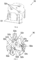
- Figures 2 to 3 illustrate the electronic control connector 30 and figures 4 to 9 illustrate the terminals 34 which are inserted inside the input orifices 32a of the electronic control connector 30, objects of the present invention.
- the electronic control connector 30 being used for electrically connecting an electronic control 50 to a hermetic compressor 200.
- the electronic control 50 can be a frequency inverter provided with various electronic circuits having different functions, such as, for example, a power circuit with input stage for electromagnetic interference filtering and a rectifier bridge stage for converting an alternating current coming from an external power source into a continuous voltage, a control circuit (microcontroller or Digital Signal Processor - DSP), an auxiliary power source for generating all internal voltages for other circuits or components of the inverter, a circuit formed by power semiconductors for driving the electric motor employed in the compressor, among others.
- a control circuit microcontroller or Digital Signal Processor - DSP
- auxiliary power source for generating all internal voltages for other circuits or components of the inverter
- a circuit formed by power semiconductors for driving the electric motor employed in the compressor among others.
- the electronic control 50 can be another type of component or a combination of other components, capable of controlling the hermetic compressor 200, such as the start-up system for compressor with single-phase motor, a thermostat system for controlling the temperature of a cooler, a motor control system with Taps for arrangement in 110V or 220V, among others.
- the electronic control 50 is used for controlling the voltage and the frequency applied to the hermetic compressor 200, specifically for variable capacity compressors 200, thus varying the pumping speed of the cooling gas, that is, its mass flow, in accordance with the system requirement and its demand for cooling.
- the hermetic compressor 200 is driven by three-phase brushless DC electric motors.
- the present invention is not limited to just this type of electric motor, such that other single-phase, two-phase or three-phase motors can be used, depending on the desired application.
- the electronic control 50 object of the present invention, can be disposed on a first face 11 of a printed circuit board 10, on a second face 12 of the printed circuit board 10 or on both faces 11, 12.
- the first face 11 is the one that faces an outer casing 150 and the second face 12 is the one facing a support surface 201 of the hermetic compressor, as detailed ahead.
- the disposition on a certain face neither establishes a limitative character, nor alters the innovative characteristics of the present invention.
- the printed circuit board 10 is a board known in the state of the art, and can be made of phenolic, fiberglass, polyester fiber, diverse specific polymer-based films, among others.
- the first face 11 and a second face 12 of the printed circuit board 10 being provided with fine copper foils, which establish conduction tracks, where the components of the electronic control 50 are soldered and electrically interconnected to each other.
- the printed circuit board 10 is provided with external feed terminals 40 of the printed circuit board 10, the terminals 40 being electrically connected to the electronic control 50 and to an external voltage feed source (not shown).
- the printed circuit board 10 is provided with at least a fixing orifice 16, which receives the electronic control connector 30, as described ahead.
- the electronic control connector 30 is made of insulating plastic materials resistant to the high electric currents to be applied to the hermetic compressor 200.
- the electronic control connector 30 comprises at least an input orifice 32a, at least a first support wall 32b, at least a second support wall 32c and at least a fixing leg 33.
- the at least a first support wall 32b and the at least a second support wall 32c are adjacent to the input orifice 32a. More specifically, the at least a first and a second support walls 32b, 32c are opposite to each other in relation to the at least an input orifice 32a, such that they substantially form a cavity or a passage duct from the outside to the inside of the connector 30.
- the at least a first support wall 32b being further provided with a recess 32d that surpasses the sides of the at least a first support wall 32b and being positioned in an intermediary region between the upper and lower ends of said first support wall 32b.
- Said electronic control connector 30 receiving therein at least an input orifice 32a at least a terminal 34, as illustrated in figures 10 and 11 and as described in greater detail ahead.
- the at least a terminal 34 is inside the at least an input orifice 32a, as described ahead and as illustrated in figures 10 and 11 .
- the at least a terminal 34 is made of phosphor bronze, capable of conducting electricity and having considerable resistance to corrosion and is approximately 0.40 millimeter (mm) thick.
- the material of the at least a terminal 34 should conduct electricity and should be resistant to corrosion and to the high electric currents to be applied to the hermetic compressor 200.
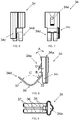
- the at least a terminal 34 comprises an upper portion 34a, a lower portion 34b, a side support projection 34c, an electric contact portion 34d and a fixing projection 34e.
- the upper portion 34a is substantially X-shaped, formed by two elliptical portions, the first portion on the horizontal axis having a wider cross-section in length (6.00 millimeters (mm)) and shorter in width compared to the second portion on the vertical axis (2.00 millimeters (mm)).
- the second portion on the vertical axis presenting one of the ends with greater curvature than the other and having an inclination A of approximately 30° and 2.00 millimeters (mm) in length.
- the intersection of the portions defines a central orifice. It is noted that it extends from the upper portion 34a to the lower portion 34b of the terminal 34.
- the central orifice is approximately 2.60 millimeters (mm) in diameter.
- Figures 4 to 9 also illustrate a side support projection 34c, which extends sidewardly along one of the ends of the horizontal portion of the upper portion 34a of the terminal 34. Said side support projection 34c extending linearly from the upper portion 34a to beyond the lower portion 34b, that is, the side support projection 34c has a greater length than the one comprised between the upper portion 34a and the lower portion 34b.
- the length between the upper portion 34a and the lower portion 34b is 6.50 millimeters (mm) and that of the side support projection 34c is 11.00 millimeters (mm).
- the side support projection 34c in its greater length than the one comprised between the upper portion 34a and the lower portion 34b is 0.60 millimeter (mm) distant from the vertical axis of the central orifice.
- the terminal 34 presents a single side support projection 34c, said embodiment does not represent a limitative character.
- the terminal 34 could comprise a plurality of side support projections 34c or even a projection 34c extending along part of or all the outer surface of the horizontal and vertical portions of the upper and lower portions 34a, 34b.
- the embodiments in which the terminal 34 does not present a single side support projection 34c do not form part of the invention.
- the electric contact portion 34d projects outwardly from the end and in an opposite direction to a vertical axis of the lower portion 34b.
- the electric contact portion 34d comprises a curvilinear shape, a V-shape or a U-shape. It is noted that the shapes cited are not compulsory, such that any other shapes could be used, provided that their functionality is substantially similar to that of the preferred shapes.
- the electric contact portion 34d is formed by a first straight portion 35, a curvilinear portion 36 and a second straight portion 37.
- the first straight portion 35 projecting from the end and in an opposite direction to the lower portion 34b, the curvilinear portion 36 starting from the end of the first straight portion 35 and a second straight portion 37 starting from the end of the curvilinear portion 36.
- the function of the second straight portion 37 is to guide the terminal 34 inside the connector 30, as seen in figure 10 and which will be described in greater detail ahead.
- the length of the first straight portion 35 is 1.40 millimeter (mm) and begins after a patch with curvature B of 140 degrees and a radius of 2.00 millimeters (mm), the curvilinear portion 36 has a curvature C of 90 degrees and radius of 2.50 millimeters (mm) and the second straight portion 37 has a length of 4.30 millimeters (mm).
- the thickness of the first straight portion 35, of the curvilinear portion 36 and of the second straight portion 37 being 0.40 millimeter (mm).
- the vertex of the curvilinear portion 36 being 1.00 millimeter (mm) higher and distant from the end of the side support projection 34c.
- the length between the end of the second straight portion 37 to the end of the terminal 34 opposite the second straight portion 37 being approximately 12.56 millimeters (mm) and the length between the vertex of the curvilinear portion 36 to the end of the terminal 34 opposite the second straight portion 37 being approximately 7.40 millimeters (mm).
- the terminal 34 comprises two electric contact portions 34d separated between a distance of 0.80 millimeter (mm) and having a maximum length between sides of approximately 4.00 millimeters (mm).
- FIGS. 4 to 9 show the fixing projection 34e in the terminal 34.
- the fixing projection 34e projects outwardly and in the opposite direction to a vertical axis of the central orifice of the terminal 34, the fixing projection 34e being disposed and extending from a point near the upper portion 34a to a point near the lower portion 34b.
- the fixing projection 34e on the terminal 34 has a height of approximately 2.90 millimeters (mm) in relation to the vertical axis of the central orifice of the terminal 34.
- the fixing projection 34e having a width of 1.50 millimeter (mm) and an angle of approximately 30 degrees in relation to the vertical axis of the central orifice of the terminal 34.
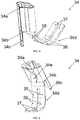
- the at least a fixing leg 33 is a projection positioned on an outer circumference of an upper surface of the electronic control 30, the at least a fixing leg 33 having an outward-sticking tooth in an opposite direction to a vertical axis of an upper surface of the electronic control 30, and may be L-shaped.
- the at least a fixing leg 33 being disposed perpendicularly to the at least a first support wall 32b and to the at least a second support wall 32c.
- the shape of the fixing leg 33 should be cooperative with the shape of the fixing orifice 16, such that the fixing leg 33 can be inserted, encased and locked on the printed circuit board 10.
- the at least a fixing leg 33 is also made from plastic materials and presents a certain elasticity, so it elastically deforms towards the input orifice 32a by applying pressure. Said characteristic enables the electronic control connector 30 to be inserted and encased in the fixing orifice 16 of the printed circuit board 10.
- the pressure on the fixing leg 33 should be interrupted, so that the fixing leg 33 elastically deforms to its initial position. This characteristic enables the electronic control connector 30 to be locked in the fixing orifice 16 of the printed circuit board 10.
- the above form of fixing is merely a preferred embodiment, and that any other form of fixing can be used, such as, for example, soldering the electronic control connector 30 on the printed circuit board 10, by soldering the at least a fixing leg 33 to the at least a fixing orifice 16. It must be emphasized that the form of fixing must guarantee permanent or provisional locking of the electronic control connector 30 in the fixing orifice 16 of the printed circuit board 10.
- the at least a terminal 34 is inserted inside the at least an input orifice 32a of the electronic control connector 30.
- the upper portion 34a and the lower portion 34b of the terminal 34 are inserted into the cavity formed between the first and the second support walls 32b, 32c and the input orifice 32a of the electronic control connector 30.
- the pressure created by the interference between the at least a fixing leg 33 and the wall of the at least an orifice 16 of the printed circuit board 10, that is, when pressing the connector 30 on the printed circuit board 10, deformation of the fixing leg 33 occurs.
- the electronic control connector 30 being encased in the at least a fixing orifice 16 on any of the faces 11, 12 of the printed circuit board 10.
- the pressure on the at least a fixing leg 33 should be interrupted, so that the fixing leg 33 elastically deforms to its initial position. This characteristic enables the electronic control connector 30 to be locked on the fixing orifice 16 of the printed circuit board 10.
- the electric contact portion 34d presents a degree of freedom of movement capable of preventing the angular movement of the electric contact portion 34d, guaranteeing the electrical connection between the electric contact portion 34d and the tracks of the printed circuit board 10 of the electronic control 50.
- the side support projection 34c acting as stopper, so that when connecting or removing the electronic control connector 30 of the connector of the hermetic compressor 210, the terminal 34 does not move, thus exercising an excessive force in the electric contact portion 34d.
- This excessive force may plastically deform the electric contact portion 34d meaning the electric contact between the electric contact portion 34d and the tracks of the printed circuit board 10 is lost.
- the electrical connection between said connector and the hermetic compressor 200 may be carried out.
- the connector of the hermetic compressor 210 comprises at least three pins and the electronic control connector 30 comprises three terminals 34. It must be emphasized that the number of terminals 34 of the electronic control 30 and the number of pins of the connector of the hermetic compressor 210 are proportional and vary according to the hermetic compressor 200 used (single-phase, two-phase, three-phase).
- the pins of the connector of the hermetic compressor 210 are inserted inside the cavity formed between the first and the second support walls 32b, 32c and the input orifice 32a of the electronic control connector 30, such that the terminal 34 of the electronic control connector 30 is electrically connected to the respective pin of the connector of the hermetic compressor 210.
- At least a seating means 20 is fixed to the first face 11 and to the second face 12 of the printed circuit board 10.
- the at least a means 20 is disposed at the ends/vertices of the printed circuit board 10, symmetrically between both faces 11, 12. Symmetry occurs by means of the connection of the at least a seating means 20 between the faces 11, 12 by means of an orifice that surpasses the ends/vertices where it is disposed.
- the at least a seating means 20 is made of elastically deformable materials, such as rubbers, polymers, springs or any other materials capable of elastically deforming by a mechanical effort (for example, compression).
- the printed circuit board 10 is provided with an ground connection point 15.
- this is a metal contact in the shape of a hook, for subsequent electrical connection to a support surface 201 of the hermetic compressor 200, as described ahead.
- the ground connection point 15 being electrically connected to the board 10 and being configured to earth an electromagnetic interference circuit 130 disposed on the printed circuit board 10.
- the hook shape is merely a preferred embodiment, and any other type of connection can be used, provided that it is capable of establishing contact with the support surface 201.
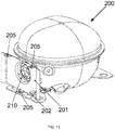
- the hermetic compressor 200 it can be noted from figure 13 that it is provided with a support surface 201 and of a connector of the hermetic compressor 210.
- the support surface 201 has a shape cooperative with the shape of the printed circuit board 10, since latter will be fixed thereon.
- the support surface 201 presents in its central region an orifice for the passage of the connector of the hermetic compressor 210.
- the connector of the hermetic compressor 210 is provided with at least three connections (male connectors), which are electrically connected to the female-type connections of the electronic control connector 30 of the printed circuit board 10.
- the number of connections depends on the type of electric motor used (single-phase, two-phase or three-phase). As described ahead, said electrical connection enables the electric motor of the hermetic compressor 200 to receive power signals of the electronic control 50.
- figure 13 shows that the support surface 201 of the hermetic compressor 200 is provided with a projection 202 and of at least an encasement 205.
- the projection 202 of the support surface 201 being configured for subsequent electrical connection with the ground connection point 15 of the printed circuit board 10, as described in greater detail ahead.
- the at least an encasement 205 being configured for receiving the outer casing 150 of the connection and fixing means.
- the hermetic compressor 200, the projection 202, the support surface 201 and the at least an encasement 205 being made of metal materials and all being grounded, to prevent damages from any electrical discharges and/or short circuits.
- the outer casing 150 of the connection means and fixing is provided with an internal cavity 151 and with an opening 152, preferably lateral, for access to the external power terminals 40 of the printed circuit board 10, as subsequently described.
- the outer casing 150 can be made of any material, especially plastic materials.
- connection and fixing means object of the present invention, in the hermetic compressor 200, especially the electrical connection and fixing of the printed circuit board 10 with the electronic control 50 to the support surface 201 of the hermetic compressor 200.
- the printed circuit board 10 with the electronic control 50 is initially placed parallel to the support surface 201 of the hermetic compressor 200 and being moved linearly until the electronic control connector 30 and the connector of the hermetic compressor 210 are aligned with each other.
- the printed circuit board 10 is connected and fixed, respectively, to the connector of the hermetic compressor 210 and to the support surface 201, in a substantially stable manner and without the need to use fixing means (such as screws). Moreover, it is noted that the electromagnetic interference filtering circuit 130 of the board 10 is grounded, since an electrical ground connection was established with the hermetic compressor 200.
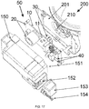
- Figure 17 illustrates the complete assembly of the connection and fixing means, object of the present invention, with the hermetic compressor 200, especially the electrical connection and the fixing of the printed circuit board 10 with the electronic control 50 to the support surface 201 of the hermetic compressor, the encapsulation of the printed circuit board 10 with the electronic control 50 by the outer casing 150 and the fixing of the outer casing 150 to the support surface 201 of the hermetic compressor 200.
- the outer casing 150 receives and encapsulates, in its internal cavity 151, the printed circuit board 10 with the electronic control 50, with the at least a seating means 20 and with the electronic control connector 30.
- the outer casing 150 establishes a contact with the at least a seating means 20 of the first face 11, the outer casing 150 being fixed to the support surface 201 of the hermetic compressor 200 by means of encasements 205 of the support surface 201.
- the external power terminals 40 of the printed circuit board 10 remain accessible from the side opening 152 of the outer casing 150.
- the side opening 152 being closed by a lid 153 and fixed by means of fixing elements 154 (such as screws).
- the present invention brings various advantages over the state of the art, shorter time and fewer number of steps for assembly on the production lines, economy by eliminating cables, practicality in assembly, disassembly, maintenance, replacement of components, low production cost, among others.
Landscapes
- Engineering & Computer Science (AREA)
- Manufacturing & Machinery (AREA)
- Microelectronics & Electronic Packaging (AREA)
- Metallurgy (AREA)
- Coupling Device And Connection With Printed Circuit (AREA)
- Multi-Conductor Connections (AREA)
- Compressor (AREA)
- Motor Or Generator Frames (AREA)
Claims (13)
- Verbinder (30) einer elektronischen Steuerung zum Verbinden eines Stifts eines Verbinders eines hermetischen Kompressors (210) mit einer Spur einer Platine (10), wobei der Verbinder (30) der elektronischen Steuerung umfasst:mindestens eine Eingabeöffnung (32a);mindestens ein Befestigungsbein (33); undmindestens ein Terminal (34), das in die mindestens eine Eingabeöffnung (32a) eingesetzt wird, um mittels eines elektrischen Kontaktabschnitts (34d) des Terminals (34) eine elektrische Verbindung zwischen dem mindestens einen Terminal (34) des Verbinders (30) der elektronischen Steuerung und den Spuren der Platine (10) einer elektronischen Steuerung (50) herzustellen,wobei der Verbinder (30) der elektronischen Steuerung angepasst ist, an einer Platine (10) und elektronischen Steuerung (50) mittels einer Befestigung zwischen dem Befestigungsbein (33) und einer Befestigungsöffnung (16) befestigt zu werden, die an der Platine (10) der elektronischen Steuerung angeordnet ist (50),wobei das Terminal (34) einen Seitenträgervorsprung (34c) umfasst, der an das Befestigungsbein (33) angrenzend angeordnet ist,wobei ein erstes Ende des Seitenträgervorsprungs (34c) an eine innere Fläche eines Hohlraums angrenzend angeordnet ist, der zwischen ersten und zweiten Trägerwänden (32b, 32c) und der Eingabeöffnung (32a) des Verbinders (30) der elektronischen Steuerung ausgebildet ist, ein zweites Ende des Seitenträgervorsprungs (34c) an die Platine (10) angrenzend angeordnet ist und der Seitenträgervorsprung (34c) auf der Platine (10) aufliegt, um eine Verformung des Terminals (34) zu vermeiden, wenn die elektrische Verbindung mit dem Stift des Verbinders des hermetischen Kompressors (210) hergestellt wird,wobei der Verbinder (30) der elektronischen Steuerung konfiguriert ist, eine Winkelbewegung des elektrischen Kontaktabschnitts (34d) zu ermöglichen, um die elektrische Verbindung zwischen dem elektrischen Kontaktabschnitt (34d) und den Spuren der Platine (10) der elektronischen Steuerung (50) sicherzustellen, während der Verbinder (30) der elektronischen Steuerung an der Platine (10) befestigt wird.
- Verbinder (30) einer elektronischen Steuerung nach Anspruch 1, dadurch gekennzeichnet, dass der Verbinder (30) der elektronischen Steuerung mittels mechanischem Einschluss zwischen dem mindestens einen Befestigungsbein (33) und der mindestens einen Befestigungsöffnung (16) an der Platine (10) befestigt ist.
- Verbinder (30) einer elektronischen Steuerung nach Anspruch 1, dadurch gekennzeichnet, dass der Verbinder (30) der elektronischen Steuerung durch Schweißen des mindestens einen Befestigungsbeins (33) an die mindestens eine Befestigungsöffnung (16) an der Platine (10) befestigt ist.
- Verbinder (30) einer elektronischen Steuerung nach Anspruch 1, dadurch gekennzeichnet, dass das mindestens eine Befestigungsbein (33) ein Vorsprung ist, der an einem Außenumfang einer oberen Fläche des Verbinders (30) der elektronischen Steuerung positioniert ist, das mindestens eine Befestigungsbein (33) einen nach außen weisenden Zahn in der gegenläufigen Richtung zu einer vertikalen Achse einer oberen Fläche des Verbinders (30) der elektronischen Steuerung aufweist, wobei das mindestens eine Befestigungsbein (33) L-förmig ist.
- Verbinder (30) einer elektronischen Steuerung nach Anspruch 4, dadurch gekennzeichnet, dass sich das mindestens eine Befestigungsbein (33) in Richtung der Eingabeöffnung (32a) durch Aufbringen von Druck elastisch verformt, was die Befestigung des Verbinders (30) der elektronischen Steuerung an der mindestens einen Befestigungsöffnung (16) der Platine (10) erlaubt, wobei sich das mindestens eine Befestigungsbein (33) elastisch in seine Anfangsposition verformt, indem das Aufbringen von Druck unterbrochen wird, was es dem Verbinder (30) der elektronischen Steuerung ermöglicht, in der mindestens einen Befestigungsöffnung (16) der Platine (10) verriegelt zu werden.
- Verbinder (30) einer elektronischen Steuerung nach Anspruch 1, gekennzeichnet, indem er ferner mindestens eine erste Trägerwand (32b) und mindestens eine zweite Trägerwand (32c) umfasst, die beide an die mindestens eine Eingabeöffnung (32a) angrenzen, wobei die mindestens eine erste und die mindestens eine zweite Trägerwand (32b, 32c) bezüglich der mindestens Eingabeöffnung (32a) einander gegenüberliegend befinden, wobei die mindestens eine erste und die mindestens eine zweite Trägerwand (32b, 32c) und die mindestens eine Eingabeöffnung (32a) einen Hohlraum ausbilden und die mindestens eine erste Trägerwand (32b) mit einem Ausschnitt versehen ist (32d).
- Verbinder (30) einer elektronischen Steuerung nach Anspruch 6, dadurch gekennzeichnet, dass das mindestens eine Terminal (34) einen oberen Abschnitt (34a), einen unteren Abschnitt (34b), einen Seitenträgervorsprung (34c), einen elektrischen Kontaktabschnitt (34d) und einen Befestigungsvorsprung (34e) umfasst, wobei der obere Abschnitt (34a) eine zentrale Öffnung umfasst, die eine Form aufweist, die mit der Form einer Eingabeöffnung (32a) des Verbinders (30) der elektronischen Steuerung zusammenwirkt, wobei sich die zentrale Öffnung von dem oberen Abschnitt (34a) zu dem unteren Abschnitt (34b) des Terminals (34) erstreckt und sich der Seitenträgervorsprung (34c) linear von dem oberen Abschnitt (34a) über den unteren Abschnitt (34b) hinaus entlang einer der Seiten des Terminals (34) erstreckt und der elektrische Kontaktabschnitt (34d) von dem Ende aus und in gegenläufiger Richtung zu einer vertikalen Achse des unteren Abschnitts (34b) vorspringt, wobei der Befestigungsvorsprung (34e) zwischen dem oberen Abschnitt (34a) und dem unteren Abschnitt (34b) des Terminals (34) angeordnet ist, wobei der Befestigungsvorsprung (34e) auswärts und in gegenläufiger Richtung zu einer vertikalen Achse der zentralen Öffnung des Terminals (34) von einem Punkt in der Nähe des oberen Abschnitts (34a) aus zu einem Punkt in der Nähe des unteren Abschnitts (34b) vorspringt.
- Verbinder (30) einer elektronischen Steuerung nach Anspruch 7, dadurch gekennzeichnet, dass der elektrische Kontaktabschnitt (34d) einen ersten geraden Abschnitt (35), der von dem Ende und in gegenläufiger Richtung zu dem unteren Abschnitt (34b) vorspringt, einen kurvenförmigen Abschnitt (36), der am Ende des ersten geraden Abschnitts (35) beginnt, und einen zweiten geraden Abschnitt (37), der am Ende des kurvenförmigen Abschnitts (36) beginnt, umfasst.
- Verbinder (30) einer elektronischen Steuerung nach Anspruch 8, dadurch gekennzeichnet, dass der obere Abschnitt (34a) and der untere Abschnitt (34b) des Terminals (34) in den Hohlraum eingeführt werden, der zwischen den ersten und zweiten Trägerwänden (32b, 32c) und der Eingabeöffnung (32a) des Verbinders (30) der elektronischen Steuerung ausgebildet ist, wobei der Befestigungsvorsprung (34e) von der Aussparung (32d) des Verbinders (30) der elektronischen Steuerung aus einwärts vorspringt und der Befestigungsvorsprung (34e) konfiguriert ist, das Terminal (34) an dem Verbinder (30) der elektronischen Steuerung zu verriegeln.
- Verbinder (30) einer elektronischen Steuerung nach Anspruch 1,
dadurch gekennzeichnet, dass der Seitenträgervorsprung (34c) auf der Platine (10) aufliegt und konfiguriert ist, zu verhindern, dass sich die elektrische Kontaktregion (34d) elastisch verformt, wobei der elektrische Kontaktabschnitt (34d) mit einem Grad von Bewegungsfreiheit ausgestattet ist, der in der Lage ist, die Winkelbewegung des elektrischen Kontaktabschnitts (34d) zu ermöglichen. - Verbinder (30) einer elektronischen Steuerung nach einem der Ansprüche 1 bis 10,
dadurch gekennzeichnet, dass der Verbinder (30) der elektronischen Steuerung elektrisch mit einem Verbinder des hermetischen Kompressors (210) verbunden werden kann. - Verbinder (30) einer elektronischen Steuerung nach Anspruch 11,
dadurch gekennzeichnet, dass mindestens ein Stift des Verbinders des hermetischen Kompressors (210) in den Hohlraum eingeführt wird, der zwischen den ersten und den zweiten Trägerwänden (32b, 32c) und der Eingabeöffnung (32a) des Verbinders (30) der elektronischen Steuerung ausgebildet ist, sodass das Terminal (34) des Verbinders (30) der elektronischen Steuerung elektrisch mit dem jeweiligen Stift des Verbinders des hermetischen Kompressors (210) verbunden ist, wobei die Anzahl der Terminals (34) der elektronischen Steuerung (30) und die Anzahl der Stifte des Verbinders des hermetischen Kompressors (210) proportional sind und dem verwendeten hermetischen Kompressor (200) entsprechend variieren. - Elektronische Steuerung (50) zur Ansteuerung eines hermetischen Kompressors (200) mit variabler Kapazität, umfassend eine Platine (10) und einen Verbinder (30) der elektronischen Steuerung wie einem der vorhergehenden Ansprüche definiert.
Applications Claiming Priority (2)
| Application Number | Priority Date | Filing Date | Title |
|---|---|---|---|
| CN201620154651 | 2016-01-15 | ||
| BR102016013673-3A BR102016013673B1 (pt) | 2016-01-15 | 2016-06-14 | Conector do controle eletrônico de um compressor hermético |
Publications (3)
| Publication Number | Publication Date |
|---|---|
| EP3206262A2 EP3206262A2 (de) | 2017-08-16 |
| EP3206262A3 EP3206262A3 (de) | 2017-10-11 |
| EP3206262B1 true EP3206262B1 (de) | 2019-10-23 |
Family
ID=58016515
Family Applications (1)
| Application Number | Title | Priority Date | Filing Date |
|---|---|---|---|
| EP17150911.0A Active EP3206262B1 (de) | 2016-01-15 | 2017-01-10 | Verbinder einer elektronischen steuerung, elektronische steuerung zur ansteuerung eines hermetischen verdichters |
Country Status (4)
| Country | Link |
|---|---|
| US (1) | US10199757B2 (de) |
| EP (1) | EP3206262B1 (de) |
| JP (1) | JP2017127185A (de) |
| CN (1) | CN107046202B (de) |
Families Citing this family (3)
| Publication number | Priority date | Publication date | Assignee | Title |
|---|---|---|---|---|
| KR101930245B1 (ko) | 2017-11-27 | 2018-12-18 | 효성전기주식회사 | 아우터 로터 타입의 bldc 모터의 방수용 개스킷 |
| JP6876154B2 (ja) * | 2018-04-18 | 2021-05-26 | 安徽美芝制冷設備有限公司Anhui Meizhi Compressor Co.,Ltd. | プラグアセンブリ、圧縮機スターター及び圧縮機アセンブリ |
| DE102019131791B8 (de) * | 2019-11-25 | 2022-10-13 | Hanon Systems | Anordnungen zum Verbinden elektrischer Anschlüsse für eine Vorrichtung zum Antreiben eines Verdichters sowie Verfahren zum Montieren der Anordnungen und Vorrichtung zum Antreiben eines Verdichters sowie Verwendung der Vorrichtung |
Family Cites Families (10)
| Publication number | Priority date | Publication date | Assignee | Title |
|---|---|---|---|---|
| JPH01142167U (de) * | 1988-03-25 | 1989-09-28 | ||
| JPH02133168U (de) * | 1989-04-03 | 1990-11-05 | ||
| JPH0982431A (ja) * | 1995-09-19 | 1997-03-28 | Whitaker Corp:The | 電気コネクタ及びその製造方法 |
| US5772453A (en) * | 1996-10-01 | 1998-06-30 | Hon Hai Precision Ind. Co., Ltd. | Side-by-side dual port USB connector |
| US5899754A (en) * | 1998-02-13 | 1999-05-04 | The Whitaker Corporation | Coaxial connector |
| JP2001263229A (ja) * | 2000-03-21 | 2001-09-26 | Toyota Autom Loom Works Ltd | 電動圧縮機 |
| JP3994731B2 (ja) * | 2001-12-18 | 2007-10-24 | 株式会社デンソー | 電動式圧縮機 |
| CN201266708Y (zh) * | 2008-04-30 | 2009-07-01 | 富士康(昆山)电脑接插件有限公司 | 电连接器端子 |
| US7690951B2 (en) * | 2008-07-08 | 2010-04-06 | Tyco Electronics Corporation | Ballast mounted connector receptacle |
| JP6096303B2 (ja) * | 2013-08-23 | 2017-03-15 | 富士通コンポーネント株式会社 | コネクタ |
-
2016
- 2016-12-28 US US15/392,344 patent/US10199757B2/en active Active
-
2017
- 2017-01-10 EP EP17150911.0A patent/EP3206262B1/de active Active
- 2017-01-13 CN CN201710024811.9A patent/CN107046202B/zh active Active
- 2017-01-13 JP JP2017004241A patent/JP2017127185A/ja not_active Ceased
Non-Patent Citations (1)
| Title |
|---|
| None * |
Also Published As
| Publication number | Publication date |
|---|---|
| US20170207560A1 (en) | 2017-07-20 |
| CN107046202A (zh) | 2017-08-15 |
| US10199757B2 (en) | 2019-02-05 |
| JP2017127185A (ja) | 2017-07-20 |
| EP3206262A3 (de) | 2017-10-11 |
| EP3206262A2 (de) | 2017-08-16 |
| CN107046202B (zh) | 2020-12-04 |
Similar Documents
| Publication | Publication Date | Title |
|---|---|---|
| KR102017677B1 (ko) | 커넥터 | |
| US7901218B2 (en) | Receptacle and a plug with fixtures to attach to substrates and engaging each other to form a power supply contact | |
| US10700471B2 (en) | System, method and means for connecting and fixing an electronic control to an airtight compressor and an airtight compressor | |
| US12266879B2 (en) | Arrangement for connecting electrical connections for a device used to drive a compressor, and device used to drive a compressor | |
| EP3206262B1 (de) | Verbinder einer elektronischen steuerung, elektronische steuerung zur ansteuerung eines hermetischen verdichters | |
| ES2765806T3 (es) | Conector de control electrónico, control electrónico para accionar un compresor hermético | |
| CN114270637A (zh) | 用于建立电连接的插入式连接件的密封装置和用于驱动具有该密封装置的压缩机的设备 | |
| EP0029328A1 (de) | Konstruktion eines elektrischen Motors | |
| US11121488B2 (en) | Connector assembly | |
| US11201424B2 (en) | Printed-circuit board connector for high-current transmission | |
| CN208489399U (zh) | 接线端子和相应的电气元件 | |
| EP3682459A1 (de) | Schaltgerät, dessen festkontakt mit einer prüfklemme versehen ist | |
| CN211294934U (zh) | 用于凸轮开关的具有一体化结构的固定触头和凸轮开关 | |
| US10468791B1 (en) | Terminal block | |
| GB2064230A (en) | Electric motor construction | |
| CN206490185U (zh) | 电磁兼容电路的接地端子和电磁兼容电路的接地装置 | |
| US20260005454A1 (en) | Multi-directional terminal block and method of making | |
| CN209119016U (zh) | 一种改进型交流接触器的静簧片组件 | |
| CN117790207A (zh) | 电气分断集成系统及其电气分断开关 | |
| BR102016013673B1 (pt) | Conector do controle eletrônico de um compressor hermético | |
| CN106450851B (zh) | 公端连接器 | |
| KR20230072815A (ko) | 전자 부품용 커넥터 조립체 | |
| CN119563383A (zh) | 变频器装配套件 | |
| CN119852758A (zh) | 导电端子、线端连接器以及电连接组合 | |
| CN121360943A (zh) | 一种连接刀片加工工艺及连接刀片 |
Legal Events
| Date | Code | Title | Description |
|---|---|---|---|
| PUAI | Public reference made under article 153(3) epc to a published international application that has entered the european phase |
Free format text: ORIGINAL CODE: 0009012 |
|
| STAA | Information on the status of an ep patent application or granted ep patent |
Free format text: STATUS: THE APPLICATION HAS BEEN PUBLISHED |
|
| PUAB | Information related to the publication of an a document modified or deleted |
Free format text: ORIGINAL CODE: 0009199EPPU |
|
| PUAI | Public reference made under article 153(3) epc to a published international application that has entered the european phase |
Free format text: ORIGINAL CODE: 0009012 |
|
| AK | Designated contracting states |
Kind code of ref document: A2 Designated state(s): AL AT BE BG CH CY CZ DE DK EE ES FI FR GB GR HR HU IE IS IT LI LT LU LV MC MK MT NL NO PL PT RO RS SE SI SK SM TR |
|
| AX | Request for extension of the european patent |
Extension state: BA ME |
|
| PUAL | Search report despatched |
Free format text: ORIGINAL CODE: 0009013 |
|
| AK | Designated contracting states |
Kind code of ref document: A3 Designated state(s): AL AT BE BG CH CY CZ DE DK EE ES FI FR GB GR HR HU IE IS IT LI LT LU LV MC MK MT NL NO PL PT RO RS SE SI SK SM TR |
|
| AX | Request for extension of the european patent |
Extension state: BA ME |
|
| RIC1 | Information provided on ipc code assigned before grant |
Ipc: H01R 12/71 20110101ALI20170904BHEP Ipc: H01R 13/11 20060101ALI20170904BHEP Ipc: H01R 12/70 20110101AFI20170904BHEP |
|
| STAA | Information on the status of an ep patent application or granted ep patent |
Free format text: STATUS: REQUEST FOR EXAMINATION WAS MADE |
|
| 17P | Request for examination filed |
Effective date: 20180409 |
|
| RBV | Designated contracting states (corrected) |
Designated state(s): AL AT BE BG CH CY CZ DE DK EE ES FI FR GB GR HR HU IE IS IT LI LT LU LV MC MK MT NL NO PL PT RO RS SE SI SK SM TR |
|
| GRAP | Despatch of communication of intention to grant a patent |
Free format text: ORIGINAL CODE: EPIDOSNIGR1 |
|
| STAA | Information on the status of an ep patent application or granted ep patent |
Free format text: STATUS: GRANT OF PATENT IS INTENDED |
|
| RIC1 | Information provided on ipc code assigned before grant |
Ipc: H01R 13/11 20060101ALI20190220BHEP Ipc: H01R 13/432 20060101ALI20190220BHEP Ipc: H01R 12/52 20110101ALI20190220BHEP Ipc: H01R 4/02 20060101ALI20190220BHEP Ipc: H01R 43/02 20060101ALI20190220BHEP Ipc: H01R 12/71 20110101ALI20190220BHEP Ipc: H01R 12/58 20110101ALI20190220BHEP Ipc: H01R 105/00 20060101ALI20190220BHEP Ipc: H01R 12/70 20110101AFI20190220BHEP |
|
| INTG | Intention to grant announced |
Effective date: 20190318 |
|
| GRAJ | Information related to disapproval of communication of intention to grant by the applicant or resumption of examination proceedings by the epo deleted |
Free format text: ORIGINAL CODE: EPIDOSDIGR1 |
|
| STAA | Information on the status of an ep patent application or granted ep patent |
Free format text: STATUS: REQUEST FOR EXAMINATION WAS MADE |
|
| INTC | Intention to grant announced (deleted) | ||
| GRAR | Information related to intention to grant a patent recorded |
Free format text: ORIGINAL CODE: EPIDOSNIGR71 |
|
| GRAS | Grant fee paid |
Free format text: ORIGINAL CODE: EPIDOSNIGR3 |
|
| STAA | Information on the status of an ep patent application or granted ep patent |
Free format text: STATUS: GRANT OF PATENT IS INTENDED |
|
| GRAA | (expected) grant |
Free format text: ORIGINAL CODE: 0009210 |
|
| STAA | Information on the status of an ep patent application or granted ep patent |
Free format text: STATUS: THE PATENT HAS BEEN GRANTED |
|
| RAP1 | Party data changed (applicant data changed or rights of an application transferred) |
Owner name: EMBRACO INDUSTRIA DE COMPRESSORES E SOLUCOES EM RE |
|
| AK | Designated contracting states |
Kind code of ref document: B1 Designated state(s): AL AT BE BG CH CY CZ DE DK EE ES FI FR GB GR HR HU IE IS IT LI LT LU LV MC MK MT NL NO PL PT RO RS SE SI SK SM TR |
|
| INTG | Intention to grant announced |
Effective date: 20190916 |
|
| REG | Reference to a national code |
Ref country code: GB Ref legal event code: FG4D |
|
| REG | Reference to a national code |
Ref country code: CH Ref legal event code: EP |
|
| REG | Reference to a national code |
Ref country code: IE Ref legal event code: FG4D |
|
| REG | Reference to a national code |
Ref country code: DE Ref legal event code: R096 Ref document number: 602017007927 Country of ref document: DE |
|
| REG | Reference to a national code |
Ref country code: AT Ref legal event code: REF Ref document number: 1194720 Country of ref document: AT Kind code of ref document: T Effective date: 20191115 |
|
| REG | Reference to a national code |
Ref country code: NL Ref legal event code: MP Effective date: 20191023 |
|
| REG | Reference to a national code |
Ref country code: SK Ref legal event code: T3 Ref document number: E 33007 Country of ref document: SK |
|
| REG | Reference to a national code |
Ref country code: LT Ref legal event code: MG4D |
|
| PG25 | Lapsed in a contracting state [announced via postgrant information from national office to epo] |
Ref country code: GR Free format text: LAPSE BECAUSE OF FAILURE TO SUBMIT A TRANSLATION OF THE DESCRIPTION OR TO PAY THE FEE WITHIN THE PRESCRIBED TIME-LIMIT Effective date: 20200124 Ref country code: PL Free format text: LAPSE BECAUSE OF FAILURE TO SUBMIT A TRANSLATION OF THE DESCRIPTION OR TO PAY THE FEE WITHIN THE PRESCRIBED TIME-LIMIT Effective date: 20191023 Ref country code: LT Free format text: LAPSE BECAUSE OF FAILURE TO SUBMIT A TRANSLATION OF THE DESCRIPTION OR TO PAY THE FEE WITHIN THE PRESCRIBED TIME-LIMIT Effective date: 20191023 Ref country code: NO Free format text: LAPSE BECAUSE OF FAILURE TO SUBMIT A TRANSLATION OF THE DESCRIPTION OR TO PAY THE FEE WITHIN THE PRESCRIBED TIME-LIMIT Effective date: 20200123 Ref country code: FI Free format text: LAPSE BECAUSE OF FAILURE TO SUBMIT A TRANSLATION OF THE DESCRIPTION OR TO PAY THE FEE WITHIN THE PRESCRIBED TIME-LIMIT Effective date: 20191023 Ref country code: BG Free format text: LAPSE BECAUSE OF FAILURE TO SUBMIT A TRANSLATION OF THE DESCRIPTION OR TO PAY THE FEE WITHIN THE PRESCRIBED TIME-LIMIT Effective date: 20200123 Ref country code: PT Free format text: LAPSE BECAUSE OF FAILURE TO SUBMIT A TRANSLATION OF THE DESCRIPTION OR TO PAY THE FEE WITHIN THE PRESCRIBED TIME-LIMIT Effective date: 20200224 Ref country code: NL Free format text: LAPSE BECAUSE OF FAILURE TO SUBMIT A TRANSLATION OF THE DESCRIPTION OR TO PAY THE FEE WITHIN THE PRESCRIBED TIME-LIMIT Effective date: 20191023 Ref country code: SE Free format text: LAPSE BECAUSE OF FAILURE TO SUBMIT A TRANSLATION OF THE DESCRIPTION OR TO PAY THE FEE WITHIN THE PRESCRIBED TIME-LIMIT Effective date: 20191023 Ref country code: LV Free format text: LAPSE BECAUSE OF FAILURE TO SUBMIT A TRANSLATION OF THE DESCRIPTION OR TO PAY THE FEE WITHIN THE PRESCRIBED TIME-LIMIT Effective date: 20191023 |
|
| PG25 | Lapsed in a contracting state [announced via postgrant information from national office to epo] |
Ref country code: IS Free format text: LAPSE BECAUSE OF FAILURE TO SUBMIT A TRANSLATION OF THE DESCRIPTION OR TO PAY THE FEE WITHIN THE PRESCRIBED TIME-LIMIT Effective date: 20200224 Ref country code: HR Free format text: LAPSE BECAUSE OF FAILURE TO SUBMIT A TRANSLATION OF THE DESCRIPTION OR TO PAY THE FEE WITHIN THE PRESCRIBED TIME-LIMIT Effective date: 20191023 Ref country code: RS Free format text: LAPSE BECAUSE OF FAILURE TO SUBMIT A TRANSLATION OF THE DESCRIPTION OR TO PAY THE FEE WITHIN THE PRESCRIBED TIME-LIMIT Effective date: 20191023 |
|
| REG | Reference to a national code |
Ref country code: ES Ref legal event code: FG2A Ref document number: 2765806 Country of ref document: ES Kind code of ref document: T3 Effective date: 20200611 |
|
| PG25 | Lapsed in a contracting state [announced via postgrant information from national office to epo] |
Ref country code: AL Free format text: LAPSE BECAUSE OF FAILURE TO SUBMIT A TRANSLATION OF THE DESCRIPTION OR TO PAY THE FEE WITHIN THE PRESCRIBED TIME-LIMIT Effective date: 20191023 |
|
| REG | Reference to a national code |
Ref country code: DE Ref legal event code: R097 Ref document number: 602017007927 Country of ref document: DE |
|
| PG2D | Information on lapse in contracting state deleted |
Ref country code: IS |
|
| PG25 | Lapsed in a contracting state [announced via postgrant information from national office to epo] |
Ref country code: IS Free format text: LAPSE BECAUSE OF FAILURE TO SUBMIT A TRANSLATION OF THE DESCRIPTION OR TO PAY THE FEE WITHIN THE PRESCRIBED TIME-LIMIT Effective date: 20200223 Ref country code: EE Free format text: LAPSE BECAUSE OF FAILURE TO SUBMIT A TRANSLATION OF THE DESCRIPTION OR TO PAY THE FEE WITHIN THE PRESCRIBED TIME-LIMIT Effective date: 20191023 Ref country code: DK Free format text: LAPSE BECAUSE OF FAILURE TO SUBMIT A TRANSLATION OF THE DESCRIPTION OR TO PAY THE FEE WITHIN THE PRESCRIBED TIME-LIMIT Effective date: 20191023 Ref country code: RO Free format text: LAPSE BECAUSE OF FAILURE TO SUBMIT A TRANSLATION OF THE DESCRIPTION OR TO PAY THE FEE WITHIN THE PRESCRIBED TIME-LIMIT Effective date: 20191023 Ref country code: CZ Free format text: LAPSE BECAUSE OF FAILURE TO SUBMIT A TRANSLATION OF THE DESCRIPTION OR TO PAY THE FEE WITHIN THE PRESCRIBED TIME-LIMIT Effective date: 20191023 |
|
| REG | Reference to a national code |
Ref country code: AT Ref legal event code: MK05 Ref document number: 1194720 Country of ref document: AT Kind code of ref document: T Effective date: 20191023 |
|
| PLBE | No opposition filed within time limit |
Free format text: ORIGINAL CODE: 0009261 |
|
| STAA | Information on the status of an ep patent application or granted ep patent |
Free format text: STATUS: NO OPPOSITION FILED WITHIN TIME LIMIT |
|
| PG25 | Lapsed in a contracting state [announced via postgrant information from national office to epo] |
Ref country code: SM Free format text: LAPSE BECAUSE OF FAILURE TO SUBMIT A TRANSLATION OF THE DESCRIPTION OR TO PAY THE FEE WITHIN THE PRESCRIBED TIME-LIMIT Effective date: 20191023 Ref country code: MC Free format text: LAPSE BECAUSE OF FAILURE TO SUBMIT A TRANSLATION OF THE DESCRIPTION OR TO PAY THE FEE WITHIN THE PRESCRIBED TIME-LIMIT Effective date: 20191023 |
|
| REG | Reference to a national code |
Ref country code: CH Ref legal event code: PL |
|
| 26N | No opposition filed |
Effective date: 20200724 |
|
| REG | Reference to a national code |
Ref country code: BE Ref legal event code: MM Effective date: 20200131 |
|
| PG25 | Lapsed in a contracting state [announced via postgrant information from national office to epo] |
Ref country code: FR Free format text: LAPSE BECAUSE OF NON-PAYMENT OF DUE FEES Effective date: 20200131 Ref country code: LU Free format text: LAPSE BECAUSE OF NON-PAYMENT OF DUE FEES Effective date: 20200110 |
|
| PG25 | Lapsed in a contracting state [announced via postgrant information from national office to epo] |
Ref country code: CH Free format text: LAPSE BECAUSE OF NON-PAYMENT OF DUE FEES Effective date: 20200131 Ref country code: LI Free format text: LAPSE BECAUSE OF NON-PAYMENT OF DUE FEES Effective date: 20200131 Ref country code: BE Free format text: LAPSE BECAUSE OF NON-PAYMENT OF DUE FEES Effective date: 20200131 Ref country code: AT Free format text: LAPSE BECAUSE OF FAILURE TO SUBMIT A TRANSLATION OF THE DESCRIPTION OR TO PAY THE FEE WITHIN THE PRESCRIBED TIME-LIMIT Effective date: 20191023 Ref country code: SI Free format text: LAPSE BECAUSE OF FAILURE TO SUBMIT A TRANSLATION OF THE DESCRIPTION OR TO PAY THE FEE WITHIN THE PRESCRIBED TIME-LIMIT Effective date: 20191023 |
|
| PG25 | Lapsed in a contracting state [announced via postgrant information from national office to epo] |
Ref country code: IE Free format text: LAPSE BECAUSE OF NON-PAYMENT OF DUE FEES Effective date: 20200110 |
|
| REG | Reference to a national code |
Ref country code: DE Ref legal event code: R082 Ref document number: 602017007927 Country of ref document: DE Representative=s name: SCHIEBER - FARAGO PATENTANWAELTE, DE Ref country code: DE Ref legal event code: R082 Ref document number: 602017007927 Country of ref document: DE Representative=s name: SCHIEBER FARAGO PATENTANWAELTE, DE |
|
| GBPC | Gb: european patent ceased through non-payment of renewal fee |
Effective date: 20210110 |
|
| PG25 | Lapsed in a contracting state [announced via postgrant information from national office to epo] |
Ref country code: GB Free format text: LAPSE BECAUSE OF NON-PAYMENT OF DUE FEES Effective date: 20210110 |
|
| PG25 | Lapsed in a contracting state [announced via postgrant information from national office to epo] |
Ref country code: MT Free format text: LAPSE BECAUSE OF FAILURE TO SUBMIT A TRANSLATION OF THE DESCRIPTION OR TO PAY THE FEE WITHIN THE PRESCRIBED TIME-LIMIT Effective date: 20191023 Ref country code: CY Free format text: LAPSE BECAUSE OF FAILURE TO SUBMIT A TRANSLATION OF THE DESCRIPTION OR TO PAY THE FEE WITHIN THE PRESCRIBED TIME-LIMIT Effective date: 20191023 |
|
| PGFP | Annual fee paid to national office [announced via postgrant information from national office to epo] |
Ref country code: IT Payment date: 20220120 Year of fee payment: 6 Ref country code: ES Payment date: 20220325 Year of fee payment: 6 |
|
| PG25 | Lapsed in a contracting state [announced via postgrant information from national office to epo] |
Ref country code: MK Free format text: LAPSE BECAUSE OF FAILURE TO SUBMIT A TRANSLATION OF THE DESCRIPTION OR TO PAY THE FEE WITHIN THE PRESCRIBED TIME-LIMIT Effective date: 20191023 |
|
| PG25 | Lapsed in a contracting state [announced via postgrant information from national office to epo] |
Ref country code: IT Free format text: LAPSE BECAUSE OF NON-PAYMENT OF DUE FEES Effective date: 20230110 |
|
| REG | Reference to a national code |
Ref country code: ES Ref legal event code: FD2A Effective date: 20240326 |
|
| PG25 | Lapsed in a contracting state [announced via postgrant information from national office to epo] |
Ref country code: ES Free format text: LAPSE BECAUSE OF NON-PAYMENT OF DUE FEES Effective date: 20230111 |
|
| PG25 | Lapsed in a contracting state [announced via postgrant information from national office to epo] |
Ref country code: ES Free format text: LAPSE BECAUSE OF NON-PAYMENT OF DUE FEES Effective date: 20230111 |
|
| PGFP | Annual fee paid to national office [announced via postgrant information from national office to epo] |
Ref country code: SK Payment date: 20251211 Year of fee payment: 10 |
|
| PGFP | Annual fee paid to national office [announced via postgrant information from national office to epo] |
Ref country code: DE Payment date: 20260121 Year of fee payment: 10 |
|
| PGFP | Annual fee paid to national office [announced via postgrant information from national office to epo] |
Ref country code: TR Payment date: 20260109 Year of fee payment: 10 |