EP3206263A1 - Anschluss und herstellungsverfahren dafür - Google Patents
Anschluss und herstellungsverfahren dafür Download PDFInfo
- Publication number
- EP3206263A1 EP3206263A1 EP15849147.2A EP15849147A EP3206263A1 EP 3206263 A1 EP3206263 A1 EP 3206263A1 EP 15849147 A EP15849147 A EP 15849147A EP 3206263 A1 EP3206263 A1 EP 3206263A1
- Authority
- EP
- European Patent Office
- Prior art keywords
- terminal
- contact portions
- piece
- counterpart terminal
- connecting pieces
- Prior art date
- Legal status (The legal status is an assumption and is not a legal conclusion. Google has not performed a legal analysis and makes no representation as to the accuracy of the status listed.)
- Withdrawn
Links
- 238000004519 manufacturing process Methods 0.000 title claims description 11
- 238000003780 insertion Methods 0.000 claims description 65
- 230000037431 insertion Effects 0.000 claims description 65
- 238000000034 method Methods 0.000 claims description 58
- 239000000463 material Substances 0.000 claims description 12
- 238000005520 cutting process Methods 0.000 claims description 5
- 238000005452 bending Methods 0.000 description 7
- 239000000428 dust Substances 0.000 description 7
- 238000007747 plating Methods 0.000 description 6
- 238000003825 pressing Methods 0.000 description 6
- 238000010586 diagram Methods 0.000 description 5
- 239000007769 metal material Substances 0.000 description 5
- 239000004020 conductor Substances 0.000 description 4
- 238000003754 machining Methods 0.000 description 4
- BQCADISMDOOEFD-UHFFFAOYSA-N Silver Chemical compound [Ag] BQCADISMDOOEFD-UHFFFAOYSA-N 0.000 description 3
- 230000000694 effects Effects 0.000 description 3
- 229910052751 metal Inorganic materials 0.000 description 3
- 239000002184 metal Substances 0.000 description 3
- 238000004080 punching Methods 0.000 description 3
- 229910052709 silver Inorganic materials 0.000 description 3
- 239000004332 silver Substances 0.000 description 3
- RYGMFSIKBFXOCR-UHFFFAOYSA-N Copper Chemical compound [Cu] RYGMFSIKBFXOCR-UHFFFAOYSA-N 0.000 description 2
- 229910000881 Cu alloy Inorganic materials 0.000 description 2
- 229910052782 aluminium Inorganic materials 0.000 description 2
- XAGFODPZIPBFFR-UHFFFAOYSA-N aluminium Chemical compound [Al] XAGFODPZIPBFFR-UHFFFAOYSA-N 0.000 description 2
- 230000000052 comparative effect Effects 0.000 description 2
- 229910052802 copper Inorganic materials 0.000 description 2
- 239000010949 copper Substances 0.000 description 2
- 230000000873 masking effect Effects 0.000 description 2
- 238000005192 partition Methods 0.000 description 2
- 229910001369 Brass Inorganic materials 0.000 description 1
- 229910000906 Bronze Inorganic materials 0.000 description 1
- FYYHWMGAXLPEAU-UHFFFAOYSA-N Magnesium Chemical compound [Mg] FYYHWMGAXLPEAU-UHFFFAOYSA-N 0.000 description 1
- 108010057081 Merozoite Surface Protein 1 Proteins 0.000 description 1
- OAICVXFJPJFONN-UHFFFAOYSA-N Phosphorus Chemical compound [P] OAICVXFJPJFONN-UHFFFAOYSA-N 0.000 description 1
- 238000009825 accumulation Methods 0.000 description 1
- DMFGNRRURHSENX-UHFFFAOYSA-N beryllium copper Chemical compound [Be].[Cu] DMFGNRRURHSENX-UHFFFAOYSA-N 0.000 description 1
- 230000015572 biosynthetic process Effects 0.000 description 1
- 239000010951 brass Substances 0.000 description 1
- 239000010974 bronze Substances 0.000 description 1
- KUNSUQLRTQLHQQ-UHFFFAOYSA-N copper tin Chemical compound [Cu].[Sn] KUNSUQLRTQLHQQ-UHFFFAOYSA-N 0.000 description 1
- 229910052749 magnesium Inorganic materials 0.000 description 1
- 239000011777 magnesium Substances 0.000 description 1
- 239000007921 spray Substances 0.000 description 1
- 239000010935 stainless steel Substances 0.000 description 1
- 229910001220 stainless steel Inorganic materials 0.000 description 1
- XLYOFNOQVPJJNP-UHFFFAOYSA-N water Substances O XLYOFNOQVPJJNP-UHFFFAOYSA-N 0.000 description 1
Images




Classifications
-
- H—ELECTRICITY
- H01—ELECTRIC ELEMENTS
- H01R—ELECTRICALLY-CONDUCTIVE CONNECTIONS; STRUCTURAL ASSOCIATIONS OF A PLURALITY OF MUTUALLY-INSULATED ELECTRICAL CONNECTING ELEMENTS; COUPLING DEVICES; CURRENT COLLECTORS
- H01R13/00—Details of coupling devices of the kinds covered by groups H01R12/70 or H01R24/00 - H01R33/00
- H01R13/02—Contact members
- H01R13/10—Sockets for co-operation with pins or blades
- H01R13/11—Resilient sockets
- H01R13/111—Resilient sockets co-operating with pins having a circular transverse section
-
- H—ELECTRICITY
- H01—ELECTRIC ELEMENTS
- H01R—ELECTRICALLY-CONDUCTIVE CONNECTIONS; STRUCTURAL ASSOCIATIONS OF A PLURALITY OF MUTUALLY-INSULATED ELECTRICAL CONNECTING ELEMENTS; COUPLING DEVICES; CURRENT COLLECTORS
- H01R13/00—Details of coupling devices of the kinds covered by groups H01R12/70 or H01R24/00 - H01R33/00
- H01R13/40—Securing contact members in or to a base or case; Insulating of contact members
- H01R13/42—Securing in a demountable manner
-
- H—ELECTRICITY
- H01—ELECTRIC ELEMENTS
- H01R—ELECTRICALLY-CONDUCTIVE CONNECTIONS; STRUCTURAL ASSOCIATIONS OF A PLURALITY OF MUTUALLY-INSULATED ELECTRICAL CONNECTING ELEMENTS; COUPLING DEVICES; CURRENT COLLECTORS
- H01R13/00—Details of coupling devices of the kinds covered by groups H01R12/70 or H01R24/00 - H01R33/00
- H01R13/02—Contact members
- H01R13/10—Sockets for co-operation with pins or blades
- H01R13/11—Resilient sockets
-
- H—ELECTRICITY
- H01—ELECTRIC ELEMENTS
- H01R—ELECTRICALLY-CONDUCTIVE CONNECTIONS; STRUCTURAL ASSOCIATIONS OF A PLURALITY OF MUTUALLY-INSULATED ELECTRICAL CONNECTING ELEMENTS; COUPLING DEVICES; CURRENT COLLECTORS
- H01R43/00—Apparatus or processes specially adapted for manufacturing, assembling, maintaining, or repairing of line connectors or current collectors or for joining electric conductors
- H01R43/16—Apparatus or processes specially adapted for manufacturing, assembling, maintaining, or repairing of line connectors or current collectors or for joining electric conductors for manufacturing contact members, e.g. by punching and by bending
Definitions
- the present invention relates to a terminal and a method for producing the same.
- Patent Document 1 JP 10-116644 A
- a plurality of protrusions provided in the cylindrical contact portion is disposed at substantially the same distance in a direction of the connection with the male terminal. Accordingly, dirt, dust, etc. attached to a surface of the male terminal are collected in a certain place on the surface of the male terminal by the protrusions of the female terminal when the male terminal is inserted into the female terminal. For this reason, there is a problem that dirt, dust, etc. are accumulated on the surface of the male terminal when the terminals are repeatedly attached and detached to and from each other, and a poor connection may occur between the terminals.
- An object of the present invention is to provide a terminal capable of ensuring an excellent connection and a method for producing the same.
- a first contact portion and a second contact portion included in a terminal connecting portion are disposed to be shifted from each other along an axial direction of the terminal connecting portion. Therefore, it is possible to reduce dirt or dust accumulated in a certain place of a counterpart terminal connected to the terminal and to attempt an excellent connection.
- Fig. 1 is a perspective view illustrating a terminal in the present embodiment
- Fig. 2 is a cross-sectional view illustrating a main body member of the terminal in the present embodiment
- Figs. 3(A) and 3(B) are a perspective view and a cross-sectional view illustrating a connecting member of the terminal in the embodiment of the invention
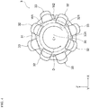
- Fig. 4 is an arrow view in a direction IV of Fig. 3(A) .
- a terminal 1 in the present embodiment is, for example, a terminal (female terminal) used for a charging connector mounted at a vehicle side of an electric vehicle, and includes a wire connecting portion 11 connected to a wire 4 at the time of mounting and a terminal connecting portion 12 connected to a counterpart terminal 5 as illustrated in Fig. 1 .
- the terminal 1 includes two members (a main body member 2 and a connecting member 3 attached to the main body member 2).
- the counterpart terminal 5 in the present embodiment has a cylindrical shape which can be inserted into the terminal connecting portion 12 of the terminal 1.
- the main body member 2 has a cross-sectional shape which is rotationally symmetric about a central axis A, and includes a connecting piece attaching portion 21 to which the connecting member 3 is attached and a wire attaching portion 22 to which the wire 4 (see Fig. 1 ) is attached at the time of mounting.
- the main body member 2 is integrally formed as a whole, and examples of a material contained in the main body member 2 may include a metal material such as pure copper, a copper alloy such as brass,. aluminum, and stainless steel, etc.
- a direction along the central axis A of the main body member 2 and a central axis C of the connecting member 3 described below in the present embodiment corresponds to an example of "an axial direction of the terminal connecting portion" of the invention.
- Various plating processes may be performed on a surface of the main body member 2 to form a plated layer 24 on the surface of the main body member 2.
- the plated layer 24 is preferably softer than a plated layer 37 of the connecting member 3 described below, and has hardness in a range of about 80 to 110 Hv.
- specific examples of the plated layer 24 may include a soft silver (Ag) plated layer having a thickness in a range of about 5 to 10 ⁇ m. In this way, when the plated layer 24 of the main body member 2 is softer than the plated layer 37 of the connecting member 3, excellent conductivity may be ensured when the wire 4 and the main body member 2 are crimped to each other.
- the plated layer 24 in the present embodiment corresponds to an example of a second plated layer in the invention.
- a hole portion 210 is formed in the connecting piece attaching portion 21, and the hole portion 210 includes a small diameter portion 211 having an inner diameter R1 and a large diameter portion 212 having an inner diameter R2 larger than the inner diameter R1 (R2 > R1).
- the small diameter portion 211 is provided on a -Y direction side of the large diameter portion 212 in Fig. 2 , and a step 215 is formed across a whole circumference on an inner wall at a boundary between the small diameter portion 211 and the large diameter portion 212 due to a difference in inner diameter therebetween.
- the connecting member 3 described below is inserted into and fixed to the hole portion 210.
- a tapered shape 213 is formed across a whole circumference at an end portion of the small diameter portion 211, and an insertion operation is facilitated due to the presence of the tapered shape 213 when the connecting member 3 is attached to the connecting piece attaching portion 21.
- the hole portion 210 in the present embodiment corresponds to an example of a hole portion of the invention.
- a hole portion 220 having a predetermined inner diameter depending on a diameter of a conductor portion of the wire 4 is formed in the wire attaching portion 22, and a tapered shape 214 is formed across a whole circumference on an end portion of the hole portion 220.
- the conductor portion of the wire 4 is inserted into the hole portion 220, and the wire attaching portion 22 is caulked from an outer circumference to press the wire attaching portion 22 against the conductor portion, thereby the conductor portion and the wire attaching portion 22 are electrically connected to each other.
- An insertion operation is facilitated due to the presence of the tapered shape 214 when the wire 4 is attached to the wire attaching portion 22.
- Examples of the wire 4 attached to the wire attaching portion 22 may include a single wire or a twisted wire formed by twisting a plurality of fine wires made of a metal material such as copper, aluminum, etc.
- the wire attaching portion 22 and the connecting piece attaching portion 21 are spatially divided by a partition wall 23. Accordingly, it is possible to inhibit water, etc. from entering the wire 4 from outside after mounting the terminal 1.
- the connecting member 3 is formed in a substantially cylindrical shape as a whole, and includes: a base portion 36, and a first connecting piece 32 and a second connecting piece 33 provided on the base portion 36.
- the base portion 36 includes a connection portion 31 through which connects the first and second connecting pieces 32 and 33 to each other, and a first insertion piece 34 and a second insertion piece 35 provided in the connection portion 31.
- the first and second connecting pieces 32 and 33 are provided to extend to the counterpart terminal 5 side (a -Y direction side of Fig. 3(A) ) from the base portion 36. Meanwhile, the first and second insertion pieces 34 and 35 are provided to extend to the wire 4 side (a +Y direction side of Fig. 3(A) ) from the connection portion 31 of the base portion 36.
- the connection portion 31 extends along a circumferential direction D (see Fig. 4 ) with a substantially constant width.
- An insertion space 30 to which the counterpart terminal 5 is inserted is formed inside the connecting member 3.
- a metal material having relatively higher Young's modulus than Young's modulus of the material contained in the main body member 2 is preferable as a material contained in the connecting member 3.
- a material contained in the connecting member 3 may include a copper alloy containing magnesium (preferably MSP-1), beryllium copper, phosphor bronze, etc. Accordingly, more excellent electrical property than that of the connecting member 3 may be assigned to the main body member 2 while allowing excellent connection between the connecting member 3 and the counterpart terminal 5.
- the base portion 36 and the first and second connecting pieces 32 and 33 are integrally formed.
- the plated layer 37 is preferably harder than the plated layer 24 of the main body member 2 described above, and has hardness in a range of about 150 to 180 Hv.
- a specific example of the plated layer 37 may include a hard silver (Ag) plated layer having a thickness in a range of about 5 to 10 ⁇ m. In this way, when the plated layer 37 of the connecting member 3 is harder than the plated layer 24 of the main body member 2, excellent wear resistance may be ensured in the connecting pieces 32 and 33 through which the counterpart terminal 5 is repeatedly inserted and removed.
- the plated layer 37 in the present embodiment corresponds to an example of a first plated layer in the invention.
- a metal layer made of the same material as that of the plated layer 37 may be further stacked on a surface of the plated layer 37 at distal ends of the first and second contact pieces 32 and 33.
- a specific example of such a metal layer may include a hard silver (Ag) layer having a thickness in a range of 40 to 50 ⁇ m.
- first connecting pieces 32 and second connecting pieces 33 are disposed at substantially equal intervals along the circumferential direction D of the insertion space 30, and the first connecting pieces 32 and the second connecting pieces 33 are alternately disposed along the circumferential direction D. Accordingly, an operation of aligning the counterpart terminal 5 to a central axis of the insertion space 30 is facilitated when the counterpart terminal 5 is inserted into the insertion space 30.
- the first connecting piece 32 and the second connecting piece 33 have substantially the same width (width along the circumferential direction D).
- the invention is not particularly limited thereto.
- the first and second connecting pieces 32 and 33 may have different widths.
- first connecting pieces 32 in total and four second connecting pieces 33 in total are provided in the connection portion 31 of the base portion 36.
- the numbers of first connecting pieces 32 and second connecting pieces provided in the connection portion 31 are not particularly limited thereto.
- Disposition of the first and second connecting pieces 32 and 33 provided in the connection portion 31 is not particularly limited to the above-described disposition. It is preferable that the four first connecting pieces 32 and the four second connecting pieces 33 are provided in the connection portion 31 as in the present embodiment in terms of improvement in connection reliability and improvement in accuracy of positioning (aligning to the central axis) when the terminal 1 is connected to the counterpart terminal 5.
- a first contact portion 321 formed by bending the first connecting piece 32 in a protrusion shape is provided at the distal end of the first connecting piece 32.
- the first connecting piece 32 is closest to the central axis C of the connecting member 3 (see Fig. 4 ) at the first contact portion 321.
- the first contact portion 321 comes into contact with a side portion of the counterpart terminal 5 to electrically connect to each other.
- a second contact portion 331 formed by bending the second connecting piece 33 in a protrusion shape is provided at the distal end of the second connecting piece 33.
- the second connecting piece 33 is closest to the central axis C of the connecting member 3 (see Fig. 4 ) at the second contact portion 331.
- the second contact portion 331 comes into contact with the side portion of the counterpart terminal 5 to electrically connect to each other.
- Shapes of the first and second contact portions 321 and 331 are not particularly limited to the above-described shapes.
- the distal ends of the first and second connecting pieces 32 and 33 may be bent inward in U-shapes to form the first and second contact portions 321 and 331.
- the first and second contact portions 321 and 331 may be formed by providing protrusions or thick portions protruding inward at the distal ends of the first and second connecting pieces 32 and 33.
- the first contact portion 321 is relatively positioned on the distal end side of the connecting member 3 (a -Y direction side of Fig. 3(B) ) with respect to the second contact portion 331.
- a length L1 of the first connecting piece 32 along a direction of the central axis C of the connecting member 3 is relatively longer than a length L2 of the connecting member 3 along the central axis C of the connecting member 3.
- positions of base ends of the first and second connecting pieces 32 and 33 are substantially the same, and thus a distal end portion of the first connecting piece 32 is relatively positioned on the distal end side (the -Y direction side of Fig.
- the first contact portion 321 is relatively positioned on the central axis C side of the connecting member 3 with respect to the second contact portion 331.
- a diameter of a virtual circle W1 contacting with the first contact portion 321 is relatively smaller than a diameter of a virtual circle W2 contacting with the second contact portion 331.
- Both the diameters of the virtual circles W1 and W2 are smaller than a diameter R5 of the counterpart terminal 5 (see Fig. 1 ).
- the terminal 1 is connected to the counterpart terminal 5
- the distal end portions of the first and second connecting pieces 32 and 33 are widened outward in a radial direction by the counterpart terminal 5. Accordingly, the counterpart terminal 5 is elastically pinched by the first and second connecting pieces 32 and 33.
- the first insertion piece 34 extends from the connection portion 31 in the +Y direction of the figure.
- two first insertion pieces 34 are provided in the connecting member 3.
- the two first insertion pieces 34 are disposed to face each other through the central axis C of the connecting member 3.
- the number of first insertion pieces 34 provided in the connecting member 3 is not particularly limited thereto. For example, it is possible to provide three or four first insertion pieces 34 disposed at substantially equal intervals along a circumferential direction of the connecting member 3.
- a locking protrusion 341 is provided on an outer surface of a distal end portion of the first insertion piece 34. When the connecting member 3 is attached to the main body member 2, the locking protrusion 341 is locked to the step 215 (see Fig. 2 ) between the small diameter portion 211 and the large diameter portion 212 in the main body member 2.
- a diameter R3 of the connecting member 3 excluding the locking protrusion 341 is less than or equal to the diameter R1 of the small diameter portion 211 of the main body member 2 (R3 ⁇ R1), and a diameter R4 of the connecting member 3 at the locking protrusion 341 is greater than the diameter R1 of the small diameter portion 211 of the main body member and less than or equal to the diameter R2 of the large diameter portion 212 (R1 ⁇ R4 ⁇ R2).
- a width of the locking protrusion 341 along the central axis C of the connecting member 3 is less than or equal to a width of the large diameter portion 212 of the main body member 2.
- the diameter R3 of the connecting member 3 excluding the locking protrusion 341 is preferably close to a size of the diameter R1 to such an extent as to allow the connecting member 3 to be inserted into the small diameter portion 211 of the main body member 2 in terms of improvement in stability when the connecting member 3 is attached to the main body member 2.
- Three second insertion pieces 35 are disposed at substantially equal intervals along the circumferential direction D between the first insertion pieces 34.
- a width of the second insertion piece 35 is relatively smaller than a width of the first insertion piece 34, and a length of the second insertion piece 35 along the central axis C of the connecting member 3 is relatively smaller than a length of the first insertion piece 34.
- the number of second insertion pieces 35 provided between the first insertion pieces 34 is not limited to the above-described number.
- a protrusion 351 protruding outward in a radial direction of the connecting member 3 is provided at a distal end portion of the second insertion piece 35.
- the protrusion 351 is disposed to come into contact with an inner wall of the small diameter portion 211 of the main body member 2 when the connecting member 3 is attached to the main body member 2.
- the protrusion 351 comes into contact with the inner wall of the small diameter portion 211 of the main body member 2, it is possible to ensure an electrical connection between the connecting member 3 and the main body member 2 and to suppress an increase in electrical resistance value between the connecting member 3 and the main body member 2.
- one protrusion 351 is provided for one second insertion piece 35.
- the number of protrusions 351 provided on the second insertion piece 35 is not particularly limited.
- first and second insertion pieces 34 and 35 and the first and second connecting pieces 32 and 33 have substantially constant widths along the central axis C of the connecting member 3.
- the invention is not particularly limited thereto.
- the first and second insertion pieces 34 and 35 or the first and second connecting pieces 32 and 33 may have non-uniform widths along the central axis C.
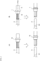
- Figs. 5(A) and 5(B) are diagrams for description of the operation of the terminal 1 in the present embodiment.
- Fig. 5(A) corresponds to a comparative example
- Fig. 5(B) corresponds to an example.
- the first contact portion 321 and the second contact portion 331 coming into contact with the counterpart terminal 5 are disposed to be shifted from each other along the directions of the central axes A and C. Accordingly, even when attachment and detachment of the terminal 1 and the counterpart terminal 5 are repeated, dirt, dust, etc. attached to the surface of the counterpart terminal 5 is dispersed in a wider place E2 than the certain place E1 of Fig. 5(A) (see Fig. 5(B) ). For this reason, it is possible to suppress accumulation of dirt, dust, etc. on the counterpart terminal 5, and to ensure an excellent connection between the terminal 1 and the counterpart terminal 5.
- the first and second contact portions 321 and 331 are shifted from each other along the directions of the central axes A and C, thereby timing at which a distal end of the counterpart terminal 5 comes into contact with the first contact portion 321 and timing at which the distal end of the counterpart terminal 5 comes into contactwith the second contact portion 331 may be shifted from each other when the counterpart terminal 5 is inserted into the insertion space 30 of the terminal 1 (see Fig. 1 ).
- the first contact portion 321 is relatively positioned on a distal end side of the terminal connecting portion 12 (in the -Y direction of Fig. 1 ) with respect to the second contact portion 331 in the axial direction of the terminal connecting portion 12. Accordingly, when the counterpart terminal 5 is inserted into the insertion space 30, first, the distal end of the counterpart terminal 5 comes into contact with the first contact portion 321.
- the first contact portion 321 is relatively positioned on a side of the central axes A and C of the terminal connecting portion 12 with respect to the second contact portion 331 (see Fig. 4 ) in the radial direction of the terminal connecting portion 12 (see Fig. 1 ). Accordingly, when the counterpart terminal 5 is inserted into the insertion space 30 of the terminal 1 (see Fig. 1 ), a distal end portion of the counterpart terminal 5 is aligned by relatively large contacting pressure by the first contact portion 321 at an initial insertion and positioned on the central axes A and C of the terminal 1, and then the distal end portion of the counterpart terminal 5 comes into contact with the second contact portion 331 by relatively small contacting pressure.
- the counterpart terminal 5 is aligned at two points (the first and second contact portions 321 and 331) along the axial direction. For this reason, it is possible to improve accuracy of positioning between terminals at the time of connection with the counterpart terminal 5.
- a length of the first connecting piece 32 along the axial direction in the terminal connecting portion 12 is relatively longer than a length of the second connecting piece 33 along the axial direction in the terminal connecting portion 12, and thus the above-described effect may be further improved.
- first connecting pieces 32 and the second connecting pieces 33 are alternately disposed at substantially equal intervals along the circumferential direction D of the insertion space 30 (see Fig. 4 ). For this reason, it is possible to improve accuracy of aligning the central axis of the counterpart terminal 5 to the central axes A and C of the terminal 1 at the time of connection with the counterpart terminal 5.
- the first connecting piece 32 is disposed to face another first connecting piece 32 through the insertion space 30, and the second connecting piece 33 is disposed to face another second connecting piece 33 through the insertion space 30. For this reason, it is possible to further improve accuracy of aligning the central axis of the counterpart terminal 5 to the central axes A and C of the terminal 1 at the time of connection with the counterpart terminal 5.
- a shape of the second connecting piece of the connecting member is not particularly limited to the above-described shape.
- the second connecting piece may be configured as illustrated in Fig. 6(A), Fig. 6(B) , and Fig. 7 .
- Fig. 6(A) and Fig. 6(B) are a perspective view and a cross-sectional view illustrating a modified example of the connecting member in the present embodiment, and Fig. 7 is an arrow view in a direction VII of Fig. 6(A) .
- a configuration of a connecting member 3B is the same as the above-described configuration of the connecting member 3 except for a second connecting piece 33B, and thus the same reference symbol as that of the connecting member 3 will be assigned to the configuration, and a description thereof will be omitted.
- the second connecting piece 33B in the modified example includes a piece-shaped portion 332 which extends from a base portion 36 of the connecting member 3B to the counterpart terminal 5 side (a -Y direction side of Fig. 6(A) ), and a wide-width portion 330 provided at a distal end of the piece-shaped portion 332.
- the piece-shaped portion 332 in the present embodiment has substantially the same width (width along the circumferential direction D (see Fig. 4 )) as that of the first connecting piece 32, and has a relatively slightly larger length (length along a Y-axis direction of Fig. 6(B) ) than that of the first connecting piece 32.
- the wide-width portion 330 has a large width (width along the circumferential direction D) than that of the piece-shaped portion 332, and is formed to extend along the circumferential direction D.
- the wide-width portion 330 and the piece-shaped portion 332 are connected to each other at an approximately center of a width along the circumferential direction D. For this reason, a T-shape is formed by the wide-width portion 330 and the piece-shaped portion 332.
- the wide-width portion 330 and the piece-shaped portion 332 may form an L-shape by connecting the piece-shaped portion 332 to an end portion of the wide-width portion 330.
- the wide-width portion 330 is formed to go around to the front side of a distal end of the first connecting piece 32. In other words, a portion of a rear end portion 330b of the wide-width portion 330 is formed so as to face the distal end of the first connecting piece 32.
- a second contact portion 331 formed by bending the wide-width portion 330 in a protrusion shape is provided in the wide-width portion 330 in the present embodiment.
- the second connecting piece 33 is closest to the central axis C of the connecting member 3 (see Fig. 7 ) at the second contact portion 331, and the second contact portion 331 comes into contact with the side portion of the counterpart terminal 5 to ensure an electrical connection at the time of connection with the counterpart terminal 5.
- the second contact portion 331 in the present embodiment is formed across a whole width of the wide-width portion 330, and a total area of the second contact portion 331 provided in one second connecting piece 33 is relatively larger than a total area of the first contact portion 321 provided in one first connecting piece 32.
- the second contact portion 331 is relatively positioned on the distal end side of the connecting member 3 (a -Y direction side of Fig. 6(B) ) with respect to the first contact portion 321.
- the second contact portion 331 is relatively positioned on the central axis C side of the connecting member 3 with respect to the first contact portion 321.
- the diameter of the virtual circle W2 coming into contact with the second contact portion 331 is relatively smaller than the diameter of the virtual circle W1 coming into contact with the first contact portion 321.
- Both the diameters of the virtual circles W1 and W2 are smaller than the diameter R5 of the counterpart terminal 5 (see Fig. 1 ).
- the terminal 1 when the terminal 1 is connected to the counterpart terminal 5, the distal end portions of the first and second connecting pieces 32 and 33 are widened outward in the radial direction by the counterpart terminal 5. Accordingly, the counterpart terminal 5 is elastically pinched by the first and second connecting pieces 32 and 33.
- a plurality of contact portions 331 may be provided with respect to one wide-width portion 330 by providing a plurality of protrusions or thick portions with respect to one wide-width portion 330.
- a total area of all the second contact portions 331 provided in one second connecting piece 33C is relatively larger than a total area of all first contact portions 321 provided in one first connecting piece 32.
- Fig. 8 is a diagram illustrating an additional modified example of the second connecting piece in the present embodiment, and is a front view obtained when the wide-width portion 330 is viewed from inside.
- the terminal may increase in temperature and an electrical resistance value between the terminals may increase.
- an increase in contact area with the counterpart terminal is limited, and thus it is difficult to improve reliability of a connection between the terminal and the counterpart terminal.
- the second connecting piece 33B has the wide-width portion 330 formed to go around to the front side of the distal end of the first connecting piece 32.
- the second contact portion 331 provided in the wide-width portion 330 is contacted with the counterpart terminal 5.
- a contact area (total area) between the terminal and the counterpart terminal 5 can be relatively increased in comparison with the terminal in which the plurality of contact pieces have the substantially same shape. Accordingly, it is possible to improve reliability of a connection between the terminal and the counterpart terminal 5.
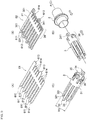
- Fig. 9(A) to Fig. 9(D) are perspective views illustrating respective producing processes of the terminal in the present embodiment.
- a cutting process by punching is performed on a plate-shaped member made of a metal material for configuring the connecting member 3 so as to form a first processed body 61 provided with a first piece shape 611 corresponding to the first connecting piece 32, a second piece shape 612 corresponding to the second connecting piece 33, a third piece shape 613 corresponding to the first insertion piece 34, and a fourth piece shape 614 corresponding to the second insertion piece 35.
- the cutting process to the plate-shaped member is not particularly limited to punching. For example, clipping, etc. may be employed.
- a pressing process is performed on the first processed body 61 having a flat plate shape and a flat shape so as to form a second processed body 62.
- a pressing process is performed on distal ends of the first piece shape 661 and the second piece shape 612 having flat shapes, thereby the first contact portion 321 bent in the protrusion shape is formed at the distal end of the first piece shape 611 and the second contact portion 331 bent in the protrusion shape is formed at the distal end of the second piece shape 612.
- a pressing process is performed on distal ends of the third transformed shape 663 and the fourth piece shape 664 having flat shapes, thereby the locking protrusion 341 is formed at the distal end of the third piece shape 613 and the protrusion 351 is formed at the distal end of the fourth piece shape 614.
- the second processed body 62 in the present embodiment corresponds to an example of a processed body of the invention.
- the process of forming the first processed body 61 (process illustrated in Fig. 9(A) ) and the process of forming the second processed body 62 (process illustrated in Fig. 9(B) ) described above correspond to an example of a first process in the invention.
- the connecting member 3 is formed by performing a process of bending the second processed body 62 in a cylindrical shape such that a portion excluding the locking protrusion 341 has a predetermined diameter R3.
- the process of bending the second processed body 62 in the cylindrical shape corresponds to an example of a second process in the invention. If the plated layer 37 is formed on the surface of the connecting member 3, a plating process is performed on the second processed body 62 bent in the cylindrical shape. If the metal layer is further stacked on the surface of the plated layer 37 of the contact portions 321 and 331, spray application, etc. is partially performed on the surface of the plated layer 37.
- the main body member 2 is formed in parallel with formation of the connecting member 3. Specifically, the main body member 2 including the contact piece attaching portion 21 having the hole portion 210 and the wire attaching portion 22 having the hole portion 220 is formed by performing a machining process on a rod-shaped member made of a metal material for configuring the main body member 2. This process of forming the main body member 2 corresponds to an example of a third process in the invention. If the plated layer 24 is formed on the surface of the main body member 2, a plating process is performed on the main body member 2 which is formed by performing the machining process on the rod-shaped member.
- Timing at which the third process is performed is not particularly limited as long as the third process is performed prior to a fourth process described below.
- the third process may be performed before the fist process, between the first process and the second process, or after the second process.
- the main body member 2 and the connecting member 3 are attached to each other.
- the main body member 2 and the connecting member 3 are disposed such that the central axis A of the main body member 2 is matched with the central axis C of the connecting member 3.
- the base portion 36 of the connecting member 3 is inserted into the hole portion 210 of the connecting piece attaching portion 21 of the main body member 2 until the locking protrusion 341 of the first insertion piece 34 is locked to the step 215 of the main body member 2 (see Fig. 2 ). Therefore, the main body member 2 and the connecting member 3 are fixed to each other, and the terminal 1 in the present embodiment may be produced.
- This process of attaching the main body member 2 and the connecting member 3 to each other corresponds to an example of the fourth process in the invention.
- the second processed body 62 is formed by performing the cutting process (punching) and the pressing process on the plate-shape member, and the connecting member 3 is formed by performing the process of bending the second processed body 62 in the cylindrical shape.
- the terminal 1 in the present embodiment is produced by inserting the connecting member 3 into the hole portion 210 of the main body member 2. Accordingly, it is possible to easily form the first and second connecting pieces 32 and 33, etc. for connection with the counterpart terminal 5. For this reason, a process of producing the terminal 1 may be facilitated, and producing cost may be reduced in comparison with a case in which the whole terminal is produced by a machining process, etc.
- the width of the connection portion 31 in the connecting member 3 may be substantially constant along the circumferential direction D, and thus it is possible to improve processing accuracy at the time of performing the process of bending the second processed body 62 in the cylindrical shape.
- Young's modulus of the material contained in the connecting member 3 of the terminal 1 is relatively larger than Young's modulus of the material contained in the main body member 2.
- the main body member 2 can be made of a material having more excellent electrical property than that of the connecting member 3 while allowing excellent electric connection by excellent elastic contact between the terminal 1 and the counterpart terminal 5 by appropriate elasticity of the first and second connecting pieces 32 and 33.
- the locking protrusion 341 formed in the first insertion piece 34 is locked to the step 215 of the main body member 2, and the protrusion 351 formed in the second insertion piece 35 comes into contact with the inner wall of the hole portion 210 of the main body member 2. For this reason, it is possible to strongly fix the connecting member 3 and the main body member 2 to each other, to ensure an electrical connection between the connecting member 3 and the main body member 2, and to suppress an increase in electrical resistance value between the connecting member 3 and the main body member 2.
- the plated layer 37 may be formed on the surface of the connecting member 3 by performing the plating process on the second processed body 62 bent in the cylindrical shape.
- the plated layer 24 may be formed on the surface of the main body member 2 by performing the plating process on the main body member 2 which is formed by performing the machining process on the rod-shaped member.
- the terminal 1 is formed by combining the main body member 2 and the connecting member 3, which are separately formed, together.
- two types of plated layers 24 and 37 may be easily formed without an additional process of attaching or peeling a masking member.
- a third connecting piece may be provided in the connecting member 3 in addition to the above-described first and second connecting pieces 32 and 33, a third contact portion coming into contact with the counterpart terminal 5 at the time of connection may be provided in the third connecting piece, and the first to third contact portions may be shifted in three steps along the directions of the central axes A and C. In this case, the same effect as that of the above-described embodiment may be accomplished.
Landscapes
- Engineering & Computer Science (AREA)
- Manufacturing & Machinery (AREA)
- Connections Effected By Soldering, Adhesion, Or Permanent Deformation (AREA)
Applications Claiming Priority (4)
| Application Number | Priority Date | Filing Date | Title |
|---|---|---|---|
| JP2014208602 | 2014-10-10 | ||
| JP2014208603A JP2016081583A (ja) | 2014-10-10 | 2014-10-10 | 端子 |
| JP2014234225A JP2016100105A (ja) | 2014-11-19 | 2014-11-19 | 端子 |
| PCT/JP2015/078834 WO2016056660A1 (ja) | 2014-10-10 | 2015-10-09 | 端子及びその製造方法 |
Publications (2)
| Publication Number | Publication Date |
|---|---|
| EP3206263A1 true EP3206263A1 (de) | 2017-08-16 |
| EP3206263A4 EP3206263A4 (de) | 2018-05-16 |
Family
ID=55653264
Family Applications (1)
| Application Number | Title | Priority Date | Filing Date |
|---|---|---|---|
| EP15849147.2A Withdrawn EP3206263A4 (de) | 2014-10-10 | 2015-10-09 | Anschluss und herstellungsverfahren dafür |
Country Status (4)
| Country | Link |
|---|---|
| US (1) | US10008800B2 (de) |
| EP (1) | EP3206263A4 (de) |
| CN (1) | CN107112673A (de) |
| WO (1) | WO2016056660A1 (de) |
Cited By (2)
| Publication number | Priority date | Publication date | Assignee | Title |
|---|---|---|---|---|
| WO2020078824A1 (de) * | 2018-10-18 | 2020-04-23 | Phoenix Contact Gmbh & Co. Kg | Elektrisches kontaktelement zum elektrischen kontaktieren mit einem gegenkontaktelement |
| EP4432479A4 (de) * | 2021-12-20 | 2025-02-26 | Japan Aviation Electronics Industry, Limited | Endgerät |
Families Citing this family (25)
| Publication number | Priority date | Publication date | Assignee | Title |
|---|---|---|---|---|
| DE102015108088A1 (de) * | 2015-05-21 | 2016-11-24 | Amad Mennekes Holding Gmbh & Co. Kg | Kontakthülse für Steckvorrichtungen |
| JP6569140B2 (ja) * | 2016-05-18 | 2019-09-04 | 住友電装株式会社 | 雌端子金具 |
| KR102608751B1 (ko) * | 2017-12-18 | 2023-12-04 | 타이코에이엠피 주식회사 | 커넥터 어셈블리 및 커넥터 어셈블리용 소켓 제조 방법 |
| US10431920B1 (en) * | 2018-04-17 | 2019-10-01 | John O. Tate | One-piece parallel multi-finger contact |
| FR3087955B1 (fr) * | 2018-10-26 | 2023-04-28 | Aptiv Tech Ltd | Ensemble de connexion, contact femelle et procede de connexion |
| WO2020235355A1 (ja) * | 2019-05-22 | 2020-11-26 | 住友電装株式会社 | 接続端子及びコネクタ |
| GB2585669B (en) * | 2019-07-10 | 2023-07-05 | Hypertac Sa | Female contact with stamped beams and method of manufacture |
| CN210668900U (zh) | 2019-10-17 | 2020-06-02 | 富士康(昆山)电脑接插件有限公司 | 同轴连接器 |
| CN211126359U (zh) * | 2019-10-17 | 2020-07-28 | 富士康(昆山)电脑接插件有限公司 | 同轴连接器 |
| DE102020100900B4 (de) * | 2020-01-16 | 2021-11-04 | Phoenix Contact E-Mobility Gmbh | Kontaktelementbaugruppe für ein Steckverbinderteil, Steckverbinderteil und Ladesystem |
| USD993923S1 (en) * | 2020-09-30 | 2023-08-01 | Molex, Llc | Connector |
| CN115528458A (zh) * | 2021-06-24 | 2022-12-27 | 矢崎总业株式会社 | 开槽端子及其制造方法 |
| WO2023284857A1 (zh) * | 2021-07-15 | 2023-01-19 | 长春捷翼汽车零部件有限公司 | 一种含有冲压弹片结构的端子 |
| CN113410685A (zh) * | 2021-07-15 | 2021-09-17 | 长春捷翼汽车零部件有限公司 | 一种含有冲压弹片结构的端子 |
| CN113612049B (zh) * | 2021-07-29 | 2024-09-17 | 中航光电科技股份有限公司 | 宝塔式接触件 |
| JP7410102B2 (ja) * | 2021-09-15 | 2024-01-09 | 矢崎総業株式会社 | コネクタ及びコネクタの製造方法 |
| JP1734991S (ja) * | 2022-08-08 | 2023-01-19 | 管継手用スリーブ | |
| USD1047918S1 (en) | 2022-10-28 | 2024-10-22 | Molex, Llc | Connector |
| USD1070775S1 (en) | 2022-10-28 | 2025-04-15 | Molex, Llc | Connector |
| USD1070776S1 (en) | 2022-10-28 | 2025-04-15 | Molex, Llc | Connector |
| USD1047919S1 (en) | 2022-10-28 | 2024-10-22 | Molex, Llc | Connector |
| USD1089104S1 (en) | 2023-11-17 | 2025-08-19 | Molex, Llc | Connector |
| USD1089105S1 (en) | 2023-11-17 | 2025-08-19 | Molex, Llc | Connector |
| CN118336419B (zh) * | 2024-06-10 | 2024-08-13 | 江苏新华陵汽车电器有限公司 | 一种汽车用线路连接头及其工作方法 |
| USD1101695S1 (en) | 2024-08-13 | 2025-11-11 | Molex, Llc | Connector |
Family Cites Families (21)
| Publication number | Priority date | Publication date | Assignee | Title |
|---|---|---|---|---|
| US4002400A (en) * | 1975-08-01 | 1977-01-11 | E. I. Du Pont De Nemours And Company | Electrical connector |
| US4784622A (en) * | 1987-07-29 | 1988-11-15 | Augat Inc. | Stamped and formed contact |
| US4906212A (en) * | 1989-04-11 | 1990-03-06 | Amp Incorporated | Electrical pin and socket connector |
| JPH04102167U (ja) * | 1991-02-12 | 1992-09-03 | 日本航空電子工業株式会社 | コンタクト |
| US5135403A (en) * | 1991-06-07 | 1992-08-04 | Amp Incorporated | Solderless spring socket for printed circuit board |
| US5667413A (en) * | 1995-11-13 | 1997-09-16 | Alcoa Fujikura Ltd. | Socket-type electrical connector |
| JP3412738B2 (ja) * | 1996-10-11 | 2003-06-03 | 矢崎総業株式会社 | 大電流用雌端子の形成方法 |
| JP3148135B2 (ja) | 1996-10-21 | 2001-03-19 | タイコエレクトロニクスアンプ株式会社 | 雌型端子 |
| US6190215B1 (en) * | 1997-01-31 | 2001-02-20 | Berg Technology, Inc. | Stamped power contact |
| CA2272458C (en) * | 1998-06-25 | 2008-03-18 | Leslie Laszlo Kerek | Hoodless electrical socket connector |
| SE517582C2 (sv) * | 1999-03-31 | 2002-06-25 | Berg Connectors Sweden Ab | Kontakthylsa |
| US6899572B1 (en) * | 1999-08-16 | 2005-05-31 | Anderson Power Products | Electrical socket contact with tines |
| EP1623485B1 (de) * | 2003-05-02 | 2014-03-12 | Anderson Power Products | Vorgespannter sockelkontakt und verfahren dafür |
| US7942682B2 (en) * | 2009-02-24 | 2011-05-17 | Tyco Electronics Corporation | Electrical connector with slider component for fault condition connection |
| JP2010211988A (ja) * | 2009-03-09 | 2010-09-24 | Matsumura Seiki:Kk | 接続端子 |
| CN102005663B (zh) * | 2010-10-19 | 2013-03-20 | 中航光电科技股份有限公司 | 冠簧笼式插针插孔组件及其插孔 |
| US9325095B2 (en) * | 2011-05-05 | 2016-04-26 | Lear Corporation | Female type contact for an electrical connector |
| JP2013098088A (ja) | 2011-11-02 | 2013-05-20 | Sumitomo Wiring Syst Ltd | 雌型端子金具 |
| JP5706352B2 (ja) * | 2012-02-03 | 2015-04-22 | ヒロセ電機株式会社 | 電気コネクタ |
| JP5995062B2 (ja) * | 2012-05-28 | 2016-09-21 | 株式会社オートネットワーク技術研究所 | ソケット端子 |
| ES2635625T3 (es) * | 2013-07-30 | 2017-10-04 | Abb Schweiz Ag | Dispositivo de conexión para un aparato conmutador |
-
2015
- 2015-10-09 US US15/507,482 patent/US10008800B2/en not_active Expired - Fee Related
- 2015-10-09 EP EP15849147.2A patent/EP3206263A4/de not_active Withdrawn
- 2015-10-09 WO PCT/JP2015/078834 patent/WO2016056660A1/ja not_active Ceased
- 2015-10-09 CN CN201580054731.7A patent/CN107112673A/zh active Pending
Cited By (3)
| Publication number | Priority date | Publication date | Assignee | Title |
|---|---|---|---|---|
| WO2020078824A1 (de) * | 2018-10-18 | 2020-04-23 | Phoenix Contact Gmbh & Co. Kg | Elektrisches kontaktelement zum elektrischen kontaktieren mit einem gegenkontaktelement |
| US11502437B2 (en) | 2018-10-18 | 2022-11-15 | Phoenix Contact Gmbh & Co. Kg | Electrical contact element for electrical contacting with a counterpart contact element |
| EP4432479A4 (de) * | 2021-12-20 | 2025-02-26 | Japan Aviation Electronics Industry, Limited | Endgerät |
Also Published As
| Publication number | Publication date |
|---|---|
| US20170302017A1 (en) | 2017-10-19 |
| EP3206263A4 (de) | 2018-05-16 |
| US10008800B2 (en) | 2018-06-26 |
| CN107112673A (zh) | 2017-08-29 |
| WO2016056660A1 (ja) | 2016-04-14 |
Similar Documents
| Publication | Publication Date | Title |
|---|---|---|
| US10008800B2 (en) | Terminal and method for producing the same | |
| CN105580213B (zh) | 端子配件 | |
| CN104335426B (zh) | 插座端子 | |
| US9136628B2 (en) | Crimp type terminal fitting | |
| EP2894722B1 (de) | Buchse | |
| JP2018026323A (ja) | 無線周波数同軸コネクタアセンブリおよび当該アセンブリの製造方法 | |
| EP2999051A1 (de) | Draht mit klemme | |
| JP2007173198A (ja) | 電気コンタクト及びメス端子 | |
| JP6652583B2 (ja) | 端子付き電線 | |
| CN105914481A (zh) | 带有压接端子的电线 | |
| EP2159880A1 (de) | Anschlussstück und an dem Anschlussstück angeschlossener Draht | |
| CN105098384B (zh) | 微电流压接端子和微电流线束 | |
| JP6263290B1 (ja) | 端子 | |
| CN106025734A (zh) | 同轴连接器 | |
| JP6543553B2 (ja) | 端子及びその製造方法 | |
| JP2008176965A (ja) | 電気接続部品及びコネクタ端子 | |
| JP6845438B2 (ja) | コネクタ端子、コネクタ端子を備えるコネクタ、及びコネクタ端子の製造方法 | |
| JP2016081583A (ja) | 端子 | |
| KR102338051B1 (ko) | 동축 커넥터 및 동축 케이블을 구비한 동축 커넥터 | |
| JP2014107079A (ja) | 多接点型雌端子 | |
| WO2015029731A1 (ja) | コネクタ | |
| JP4823844B2 (ja) | ソケット端子 | |
| CN110088982B (zh) | 配备有接触元件的电连接元件 | |
| JP2016100105A (ja) | 端子 | |
| JP6514926B2 (ja) | 端子 |
Legal Events
| Date | Code | Title | Description |
|---|---|---|---|
| PUAI | Public reference made under article 153(3) epc to a published international application that has entered the european phase |
Free format text: ORIGINAL CODE: 0009012 |
|
| 17P | Request for examination filed |
Effective date: 20170222 |
|
| AK | Designated contracting states |
Kind code of ref document: A1 Designated state(s): AL AT BE BG CH CY CZ DE DK EE ES FI FR GB GR HR HU IE IS IT LI LT LU LV MC MK MT NL NO PL PT RO RS SE SI SK SM TR |
|
| AX | Request for extension of the european patent |
Extension state: BA ME |
|
| DAV | Request for validation of the european patent (deleted) | ||
| DAX | Request for extension of the european patent (deleted) | ||
| A4 | Supplementary search report drawn up and despatched |
Effective date: 20180418 |
|
| RIC1 | Information provided on ipc code assigned before grant |
Ipc: H01R 43/16 20060101ALI20180412BHEP Ipc: H01R 13/42 20060101ALI20180412BHEP Ipc: H01R 13/11 20060101AFI20180412BHEP |
|
| STAA | Information on the status of an ep patent application or granted ep patent |
Free format text: STATUS: THE APPLICATION IS DEEMED TO BE WITHDRAWN |
|
| 18D | Application deemed to be withdrawn |
Effective date: 20181120 |