EP3206268B1 - Verfahren zum feuchtigkeitsdichten abdichten eines elektrischen kupplungsteils - Google Patents
Verfahren zum feuchtigkeitsdichten abdichten eines elektrischen kupplungsteils Download PDFInfo
- Publication number
- EP3206268B1 EP3206268B1 EP16305150.1A EP16305150A EP3206268B1 EP 3206268 B1 EP3206268 B1 EP 3206268B1 EP 16305150 A EP16305150 A EP 16305150A EP 3206268 B1 EP3206268 B1 EP 3206268B1
- Authority
- EP
- European Patent Office
- Prior art keywords
- contact carrier
- holes
- wires
- contact
- line
- Prior art date
- Legal status (The legal status is an assumption and is not a legal conclusion. Google has not performed a legal analysis and makes no representation as to the accuracy of the status listed.)
- Active
Links
Images
Classifications
-
- H—ELECTRICITY
- H01—ELECTRIC ELEMENTS
- H01R—ELECTRICALLY-CONDUCTIVE CONNECTIONS; STRUCTURAL ASSOCIATIONS OF A PLURALITY OF MUTUALLY-INSULATED ELECTRICAL CONNECTING ELEMENTS; COUPLING DEVICES; CURRENT COLLECTORS
- H01R43/00—Apparatus or processes specially adapted for manufacturing, assembling, maintaining, or repairing of line connectors or current collectors or for joining electric conductors
- H01R43/20—Apparatus or processes specially adapted for manufacturing, assembling, maintaining, or repairing of line connectors or current collectors or for joining electric conductors for assembling or disassembling contact members with insulating base, case or sleeve
- H01R43/24—Assembling by moulding on contact members
-
- H—ELECTRICITY
- H01—ELECTRIC ELEMENTS
- H01R—ELECTRICALLY-CONDUCTIVE CONNECTIONS; STRUCTURAL ASSOCIATIONS OF A PLURALITY OF MUTUALLY-INSULATED ELECTRICAL CONNECTING ELEMENTS; COUPLING DEVICES; CURRENT COLLECTORS
- H01R43/00—Apparatus or processes specially adapted for manufacturing, assembling, maintaining, or repairing of line connectors or current collectors or for joining electric conductors
- H01R43/005—Apparatus or processes specially adapted for manufacturing, assembling, maintaining, or repairing of line connectors or current collectors or for joining electric conductors for making dustproof, splashproof, drip-proof, waterproof, or flameproof connection, coupling, or casing
Definitions
- the invention relates to a method for moisture-tight sealing of an electrical coupling part according to the preamble of patent claim 1.
- Such a method is for example from the EP 2 099 099 B1 out.
- “Coupling” in the context of the invention may be a plug with pins or a box with can contacts.
- Contact elements are thus either the plug pins or the can contacts.
- the contact elements are inserted into through holes of prefabricated contact carriers made of insulating material.
- the reasons of cost usually very simple, such as metal strips, shaped contact elements may be equipped with a locking element, by which they are secured after insertion into the contact carrier against axial displacement. In such contact carriers measures must be taken to protect in particular the joints of contact elements and conductors of a connected line from moisture and the contact elements, if necessary, before the spray material of a protective body produced by injection molding.
- an electrical connector with a thermoplastic material housing having a through opening.
- a contact is arranged in the opening of the housing.
- a connection wire can be connected to the contact, which can be used to connect the contact to a printed circuit.
- the connecting wire can be the conductor of a cable be.
- the contact is defined in the opening of the housing by the use of a heated tool, by means of which the material of the housing is displaced so that it presses against the contact. As a result, the opening of the housing is sealed so that impurities can not pass.
- the wire is soldered to the protruding end of the housing from the housing.
- An insulating body is then injected around the junction between contact and wire, which extends to the housing and rests against the end face.
- EP 2 099 099 B1 shows an electrical coupling part with connected electrical line, which has at least two designed as insulated conductors wires.
- the coupling part has a contact carrier made of mechanically stable insulating material having at least two through-holes, in each of which an electrical contact element is arranged, which is connected to one of the electrical conductors of the provided with a sheath of insulating material line.
- a sealing element with a clamping fit is attached to each core during the production of the coupling part, through which the respective through hole of the contact carrier is sealed.
- the contact carrier also has a pointing in the direction of the line approach to which a clamp body is attached, which clamps the wires of the line.
- an injection molded protective body of insulating material is formed, which extends over the sheath of the conduit.
- the invention has the object of developing the initially described method so that the through holes of the contact body can be sealed in a simple manner.
- the through holes of the contact carrier are sealed by the material thereof. Additional sealing elements are not used and in particular also not needed. Corresponding operations for mounting of sealing elements thus continue.
- the through holes of the contact carrier are sealed in a simple manner and without additional material.
- the moisture-proof cover of the line-side end of the contact carrier is achieved by the protective body, which is produced by injection molding. It encloses in the finished coupling part, the line-side end of the contact carrier and extends beyond the line connected to the same.
- the tool by which the material of the contact carrier is moved into the through holes of the contact carrier, is advantageously applied in the region of the line-side end of the contact carrier. After completion of the process possibly existing dents of the contact carrier on its outer surface can then be covered easily and without increased material costs by the protective body.
- the contact carrier is deformed directly at its line-side end. It could be attached to the same at this end of the contact carrier and a thickening thereof, for example in the form of a radially outwardly projecting bead. Such a bead would be advantageously sized so that their material is sufficient to close the through holes of the contact carrier.
- a tool for carrying out the method can be used for example and advantageously an ultrasonic welding system.
- other systems can be used with the heat and pressure in the sense described can be applied to the contact carrier, for example, a hot Stem.
- a contact carrier used in the method according to the invention consists of a mechanically stable plastic, such as polyamide or polypropylene or polybutylene terephthalate. Its material can be converted by heat and pressure load in a flowable or viscous state.
- Line in the context of the invention may be a line with a common jacket surrounding the wires. But it can also consist only of the longitudinally interconnected wires.
- a contact carrier which has two parallel and spaced-apart through holes 2 and 3.
- contact elements 4 and 5 are arranged undisturbed.
- the contact elements 4 and 5 can be used as plug pins or as Bushings be executed.
- an electrical line 10 is connected to the contact elements 4 and 5 .
- insulating materials for the wires for example, polyvinyl chloride or crosslinked polyethylene can be used.
- the line 10 has in the illustrated embodiment, an insulating material, such as polyvinyl chloride or polyurethane, existing jacket 11, which surrounds the two wires 8 and 9 as a common jacket.
- an in Fig. 6 illustrated coupling part K is for example as follows:
- the wires 8 and 9 are freed from the jacket 11 at the end of the line 10 to a predeterminable length.
- the thus exposed cores 8 and 9 are stripped at their ends, so that their conductors 6 and 7 are available for contacting purposes.
- the contact elements 4 and 5 are then electrically connected to the conductors 6 and 7, for example by crimping. They are then inserted together with the wires 8 and 9 in the through holes 2 and 3 to a locking position in which the contact elements 4 and 5 are fixed immovably.
- a tool is applied to the contact carrier 1 at least at one point over the wires 8 and 9 from the outside, which is, for example and advantageously, an ultrasonic welding system which has a sonotrode 12 and an anvil 13.
- the contact carrier 1 is in carrying out the process on the anvil 13.
- the sonotrode 12 is then brought by movement in the direction of arrow P until it rests against the contact carrier 1 and pressed against the same.
- the material of the contact carrier 1 is heated by the vibrations of the sonotrode 12 lying in the ultrasonic range so far that it flows into the through holes 2 and 3 and completely closes them.
- the wires 8 and 9 are then embedded all around in the tight-fitting material of the contact carrier 1 and the through holes 2 and 3 are closed.
- a protective body 14 is sprayed around the end of the contact carrier 1, which extends over the line 10.
- the finished coupling part K goes out Fig. 6 out.
- the contact surface of the sonotrode 12 of the ultrasonic welding system can be adapted to the shape and structure of the line 10, which has two wires 8 and 9 in the illustrated embodiment.
- the sonotrode 12 may advantageously have in its central region projections 15 and 16, which lie in a region of the contact carrier 1, which is located above the two wires 8 and 9.
- the contact carrier 1 is deformed in accordance with the preceding embodiments in at least one of the wires 8 and 9 detected area, namely from the material of the contact carrier 1 itself, without additional material costs. It is also possible to close the through-holes 2 and 3 of the contact carrier 1 directly at its line-side end. For this purpose, for example, at this end of the contact carrier 1, a radially outwardly projecting bead 17 may be attached, as it is in Fig. 7 is shown. The bead 17 is advantageously dimensioned so that its material causes a complete sealing of the through holes 2 and 3 on the end face of the contact carrier 1.
- a hot stamping system could also be used. It has, for example, a heatable stamp, which is pressed against the contact carrier 1 at least at one point from the outside.
Landscapes
- Engineering & Computer Science (AREA)
- Manufacturing & Machinery (AREA)
- Connections Effected By Soldering, Adhesion, Or Permanent Deformation (AREA)
- Lining Or Joining Of Plastics Or The Like (AREA)
Description
- Die Erfindung bezieht sich auf ein Verfahren zum feuchtigkeitsdichten Abdichten eines elektrischen Kupplungsteils gemäß dem Oberbegriff des Patentanspruchs 1.
- Ein solches Verfahren geht beispielsweise aus der
EP 2 099 099 B1 hervor. - "Kupplungsteil" im Sinne der Erfindung können ein Stecker mit Steckerstiften oder eine Dose mit Dosenkontakten sein. "Kontaktelemente" sind also entweder die Steckerstifte oder die Dosenkontakte. Neben Konstruktionen, bei denen diese Kontaktelemente fest in Isolierstoffträger eingebettet sind, gibt es Anordnungen, bei denen die Kontaktelemente in Durchgangslöcher von vorgefertigten Kontaktträgern aus Isoliermaterial eingesetzt werden. Die aus Kostengründen meist sehr einfach, beispielsweise aus Blechstreifen, geformten Kontaktelemente können mit einem Rastelement ausgerüstet sein, durch welches sie nach dem Einsetzen in den Kontaktträger gegen axiale Verschiebung gesichert sind. Bei derartigen Kontaktträgern müssen Maßnahmen getroffen werden, um insbesondere die Verbindungsstellen von Kontaktelementen und Leitern einer angeschlossenen Leitung vor Feuchtigkeit und die Kontaktelemente gegebenenfalls vor dem Spritzmaterial eines durch Spritzgießen hergestellten Schutzkörpers zu schützen.
- Aus der
US 5,590,463 A geht ein Verfahren zur Herstellung eines elektrischen Verbinders mit einem aus thermoplastischem Material bestehenden Gehäuse hervor, das eine durchgehende Öffnung hat. In der Öffnung des Gehäuses ist ein Kontakt angeordnet. An den Kontakt kann ein Verbindungsdraht angeschlossen werden, über den der Kontakt mit einer gedruckten Schaltung verbunden werden kann. Der Verbindungsdraht kann der Leiter eines Kabels sein. Der Kontakt wird in der Öffnung des Gehäuses durch den Einsatz eines beheizten Werkzeugs festgelegt, mittels dessen Material des Gehäuses so verschoben wird, dass es gegen den Kontakt drückt. Dadurch ist die Öffnung des Gehäuses so abgedichtet, dass Verunreinigungen nicht hindurchtreten können. Danach wird der Draht an dem aus dem Gehäuse herausragenden Ende des Kontakts angelötet. Ein Isolierkörper wird daraufhin um die Verbindungsstelle zwischen Kontakt und Draht herumgespritzt, welcher sich bis zum Gehäuse erstreckt und an dessen Stirnseite anliegt. - Aus der eingangs erwähnten
EP 2 099 099 B1 geht ein elektrisches Kupplungsteil mit angeschlossener elektrischer Leitung hervor, die mindestens zwei als isolierte Leiter ausgeführte Adern aufweist. Das Kupplungsteil hat einen Kontaktträger aus mechanisch stabilem Isoliermaterial mit mindestens zwei Durchgangslöchern, in denen jeweils ein elektrisches Kontaktelement angeordnet ist, das mit einem der elektrischen Leiter der mit einem Mantel aus Isoliermaterial versehenen Leitung verbunden ist. Innerhalb des Kontaktträgers wird bei der Herstellung des Kupplungsteils auf jeder Ader ein Dichtelement mit Klemmsitz angebracht, durch welches das jeweilige Durchgangsloch des Kontaktträgers dicht verschlossen ist. Der Kontaktträger hat außerdem einen in Richtung der Leitung weisenden Ansatz, an dem ein Klemmkörper angebracht ist, welcher die Adern der Leitung einklemmt. Um den Klemmkörper herum wird ein durch Spritzgießen erzeugter Schutzkörper aus Isoliermaterial herumgeformt, der sich bis über den Mantel der Leitung erstreckt. - Der Erfindung liegt die Aufgabe zugrunde, das eingangs geschilderte Verfahren so weiterzubilden, dass die Durchgangslöcher des Kontaktkörpers auf einfache Art und Weise abgedichtet werden können.
- Diese Aufgabe wird entsprechend den kennzeichnenden Merkmalen des Patentanspruchs 1 gelöst.
- Durch dieses Verfahren werden die Durchgangslöcher des Kontaktträgers durch das Material desselben dicht verschlossen. Zusätzliche Dichtelemente werden nicht eingesetzt und insbesondere auch nicht benötigt. Entsprechende Arbeitsgänge zur Montage von Dichtelementen fallen also fort. Die Durchgangslöcher des Kontaktträgers sind so auf einfache Art und Weise und ohne zusätzliches Material dicht verschlossen. Die feuchtigkeitsdichte Abdeckung des leitungsseitigen Endes des Kontaktträgers wird durch den Schutzkörper erreicht, der durch Spritzgießen erzeugt wird. Er umschließt im fertiggestellten Kupplungsteil das leitungsseitige Ende des Kontaktträgers und erstreckt sich bis über die an denselben angeschlossene Leitung.
- Das Werkzeug, durch welches das Material des Kontaktträgers in die Durchgangslöcher des Kontaktträgers hinein bewegt wird, wird mit Vorteil im Bereich des leitungsseitigen Endes des Kontaktträgers angelegt. Nach Beendigung des Verfahrens möglicherweise vorhandene Eindellungen des Kontaktträgers an seiner äußeren Oberfläche können dann einfach und ohne erhöhten Materialaufwand durch den Schutzköper abgedeckt werden.
- Das gilt auch dann, wenn der Kontaktträger direkt an seinem leitungsseitigen Ende verformt wird. Dabei könnte an diesem Ende des Kontaktträgers auch eine Verdickung desselben angebracht sein, beispielsweise in Form einer radial nach außen abstehenden Wulst. Eine solche Wulst wäre mit Vorteil so zu bemessen, dass ihr Material ausreicht, um die Durchgangslöcher des Kontaktträgers zu verschließen.
- Als Werkzeug für die Durchführung des Verfahrens kann beispielsweise und mit Vorteil eine Ultraschall-Schweißanlage eingesetzt werden. Es können aber auch andere Anlagen verwendet werden, mit den Wärme und Druck im geschilderten Sinne auf den Kontaktträger aufgebracht werden können, beispielsweise eine Heißstemmanlage.
- Das Verfahren nach der Erfindung wird anhand der Zeichnungen in Ausführungsbeispielen erläutert.
- Es zeigen:
-
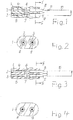
Fig. 1 einen Kontaktträger für ein mit dem Verfahren nach der Erfindung herstellbares Kupplungsteils in einem ersten Zwischenzustand. -
Fig. 2 einen Schnitt durchFig. 1 längs der Linie II - II in vergrößerter Darstellung. -
Fig. 3 den Kontaktträger nachFig. 1 in einem zweiten Zwischenzustand. -
Fig. 4 einen Schnitt durchFig. 3 längs der Linien IV - IV ebenfalls in vergrößerter Darstellung. -
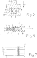
Fig. 5 einen Anordnung mit Werkzeug zur Durchführung des Verfahrens nach der Erfindung in schematischer Darstellung. -
Fig. 6 ein mit dem Verfahren nach der Erfindung hergestelltes fertiges Kupplungsteil. -
Fig. 7 einen gegenüberFig. 1 veränderten Kontaktträger. - Ein bei dem Verfahren nach der Erfindung eingesetzter Kontaktträger besteht aus einem mechanisch stabilen Kunststoff, wie beispielsweise Polyamid oder Polypropylen oder Polybutylenterephthalat. Sein Material läßt sich durch Wärme- und Druckbelastung in einen fließfähigen bzw. zähflüssigen Zustand überführen.
- Das Verfahren nach der Erfindung wird im folgenden im Zusammenhang mit einer zwei elektrische Adern aufweisenden elektrischen Leitung und einem entsprechend aufgebauten Kontaktträger mit zwei Durchgangslöchern erläutert. Es kann auch für Leitungen mit mehr als zwei Adern und dementsprechend Kontaktträger mit mehr als zwei Durchgangslöchern eingesetzt werden. "Leitung" im Sinne der Erfindung kann eine Leitung mit einem die Adern umgebenden gemeinsamen Mantel sein. Sie kann aber auch nur aus den in Längsrichtung miteinander verbundenen Adern bestehen.
- Mit 1 ist ein Kontaktträger bezeichnet, der zwei parallel und mit Abstand zueinander verlaufende Durchgangslöcher 2 und 3 aufweist. In den Durchgangslöchern 2 und 3 sind Kontaktelemente 4 und 5 unverrutschbar angeordnet. Die Kontaktelemente 4 und 5 können als Steckerstifte oder als Buchsen ausgeführt sein. An die Kontaktelemente 4 und 5 sind elektrische Leiter 6 und 7 von zwei Adern 8 und 9, das sind isolierte elektrische Leiter, einer elektrischen Leitung 10 angeschlossen. Als Isoliermaterialien für die Adern können beispielsweise Polyvinylchlorid oder vernetztes Polyethylen eingesetzt werden. Die Leitung 10 hat im dargestellten Ausführungsbeispiel einen aus Isoliermaterial, wie beispielsweise Polyvinylchlorid oder Polyurethan, bestehenden Mantel 11, der die beiden Adern 8 und 9 als gemeinsamer Mantel umgibt.
- Zur Herstellung eines in
Fig. 6 dargestellten Kupplungsteils K wird beispielsweise wie folgt vorgegangen:
Die Adern 8 und 9 werden am Ende der Leitung 10 auf einer vorgebbaren Länge vom Mantel 11 befreit. Die dadurch freigelegten Adern 8 und 9 werden an ihren Enden abisoliert, so daß ihre Leiter 6 und 7 für Kontaktierungszwecke zur Verfügung stehen. Die Kontaktelemente 4 und 5 werden dann elektrisch leitend mit den Leitern 6 und 7 verbunden, beispielsweise durch Crimpen. Sie werden danach gemeinsam mit den Adern 8 und 9 in die Durchgangslöcher 2 und 3 bis in eine Verriegelungsposition eingeschoben, in welcher die Kontaktelemente 4 und 5 unverrückbar festgelegt sind. - Anschließend wird an den Kontaktträger 1 zumindest an einer Stelle über den Adern 8 und 9 von außen ein Werkzeug angelegt, bei dem es sich beispielweise und mit Vorteil um eine Ultraschall-Schweißanlage handelt, die eine Sonotrode 12 und einen Amboß 13 aufweist. Der Kontaktträger 1 liegt bei Durchführung des Verfahrens auf dem Amboß 13 auf. Die Sonotrode 12 wird dann durch Bewegung in Richtung des Pfeiles P bis zur Anlage am Kontaktträger 1 gebracht und gegen denselben gedrückt. Nach Einschaltung der Anlage wird das Material des Kontaktträgers 1 durch die im Ultraschallbereich liegenden Schwingungen der Sonotrode 12 so weit erwärmt, dass es in die Durchgangslöcher 2 und 3 fließt und diese vollständig verschließt. Die Adern 8 und 9 sind dann rundum in das dicht anliegende Material des Kontaktträgers 1 eingebettet und die Durchgangslöcher 2 und 3 sind verschlossen. Abschließend wird um das Ende des Kontaktträgers 1 ein Schutzkörper 14 herumgespritzt, der sich bis über die Leitung 10 erstreckt. Das fertige Kupplungsteil K geht aus
Fig. 6 hervor. - Die Anlagefläche der Sonotrode 12 der Ultraschall-Schweißanlage kann an die Form und den Aufbau der Leitung 10 angepaßt sein, die im dargestellten Ausführungsbeispiel zwei Adern 8 und 9 aufweist. So kann die Sonotrode 12 in ihrem mittleren Bereich mit Vorteil Vorsprünge 15 und 16 haben, die in einem Bereich des Kontaktträgers 1 liegen, der sich über den beiden Adern 8 und 9 befindet.
- Der Kontaktträger 1 wird entsprechend den vorangehenden Ausführungen in mindestens einem die Adern 8 und 9 erfassenden Bereich verformt, und zwar aus dem Material des Kontaktträgers 1 selbst, ohne zusätzlichen Materialaufwand. Dieser Bereich liegt mit Vorteil am leitungsseitigen Ende des Kontaktträgers 1. Es ist aber auch möglich, die Durchgangslöcher 2 und 3 des Kontaktträgers 1 direkt an seinem leitungsseitigen Ende zu verschließen. Dazu kann beispielsweise an diesem Ende des Kontaktträgers 1 eine radial nach außen abstehende Wulst 17 angebracht sein, so wie es in
Fig. 7 dargestellt ist. Die Wulst 17 ist mit Vorteil so bemessen, daß ihr Material eine vollständige Abdichtung der Durchgangslöcher 2 und 3 an der Stirnfläche des Kontaktträgers 1 bewirkt. - Statt einer Ultraschall-Schweißanlage könnte beispielsweise auch eine Heißstemmanlage eingesetzt werden. Sie hat beispielsweise einen beheizbaren Stempel, der an mindestens einer Stelle von außen gegen den Kontaktträger 1 gedrückt wird.
Claims (4)
- Verfahren zum feuchtigkeitsdichten Abdichten eines elektrischen Kupplungsteils, das einen aus Kunststoff bestehenden Kontaktträger (1) aufweist, welcher mindestens zwei mit Abstand und parallel zueinander verlaufende Durchgangslöcher (2,3) hat, bei welchem in die Durchgangslöcher (2,3) elektrische Kontaktelemente (4,5), an die jeweils als von einer Isolierung umgebene elektrische Leiter ausgeführte Adern (8,9) einer elektrischen Leitung (10) angeschlossen sind, so eingesetzt werden, dass in jedem Durchgangsloch (2,3) ein Kontaktelement (4,5) und die an dasselbe angeschlossene Ader (8,9) angeordnet sind, bei welchem die Adern (8,9) an einem Ende des Kontaktträgers (1) aus den Durchgangslöchern (2,3) herausgeführt werden und mit welchem um das leitungsseitige Ende des Kupplungsteils ein durch Spritzgießen erzeugter Schutzkörper (14) herumgeformt wird, der sich bis über die Leitung (10) erstreckt,
dadurch gekennzeichnet,- dass der Kontaktträger (1) nach dem Einsetzen von Kontaktelementen (4,5) und angeschlossenen Adern (8,9) in die Durchgangslöcher (2,3) zunächst an mindestens einer Stelle im Bereich der in den Durchgangslöchern (2,3) angeordneten Adern (8,9) durch Aufbringen von Wärme und Druck mittels eines außen an den Kontaktträger (1) angelegten Werkzeugs derart verformt wird, dass sein Material sich rundum dicht an die Isolierung der Adern (8,9) anlegt, und- dass der Schutzkörper (14) danach um die Enden von Kontaktträger (1) und Leitung (10) herumgespritzt wird. - Verfahren nach Anspruch 1, dadurch gekennzeichnet, dass am Ende des Kontaktträgers (1) eine radial nach außen abstehende Wulst (17) angebracht ist, die so bemessen ist, dass ihr Material durch das Aufbringen von Wärme und Druck mittels des Werkzeugs eine vollständige Abdichtung der Durchgangslöcher (2,3) an der Stirnfläche des Kontaktträgers (1) bewirkt.
- Verfahren nach Anspruch 1 oder 2, dadurch gekennzeichnet, dass als Werkzeug eine Ultraschall-Schweißanlage verwendet wird.
- Verfahren nach Anspruch 1 oder 2, dadurch gekennzeichnet, dass als Werkzeug eine Heißstemmanlage verwendet wird.
Priority Applications (1)
| Application Number | Priority Date | Filing Date | Title |
|---|---|---|---|
| EP16305150.1A EP3206268B1 (de) | 2016-02-09 | 2016-02-09 | Verfahren zum feuchtigkeitsdichten abdichten eines elektrischen kupplungsteils |
Applications Claiming Priority (1)
| Application Number | Priority Date | Filing Date | Title |
|---|---|---|---|
| EP16305150.1A EP3206268B1 (de) | 2016-02-09 | 2016-02-09 | Verfahren zum feuchtigkeitsdichten abdichten eines elektrischen kupplungsteils |
Publications (2)
| Publication Number | Publication Date |
|---|---|
| EP3206268A1 EP3206268A1 (de) | 2017-08-16 |
| EP3206268B1 true EP3206268B1 (de) | 2018-08-15 |
Family
ID=55361446
Family Applications (1)
| Application Number | Title | Priority Date | Filing Date |
|---|---|---|---|
| EP16305150.1A Active EP3206268B1 (de) | 2016-02-09 | 2016-02-09 | Verfahren zum feuchtigkeitsdichten abdichten eines elektrischen kupplungsteils |
Country Status (1)
| Country | Link |
|---|---|
| EP (1) | EP3206268B1 (de) |
Family Cites Families (5)
| Publication number | Priority date | Publication date | Assignee | Title |
|---|---|---|---|---|
| DE3417811C1 (de) * | 1984-05-14 | 1985-10-17 | kabelmetal electro GmbH, 3000 Hannover | Verfahren zum Anbringen eines Kupplungsteils am Ende einer elektrischen Leitung |
| DE9410092U1 (de) * | 1994-06-22 | 1994-08-11 | ke autoelectric GmbH, 92685 Floß | Kupplungsteil einer elektrischen Leitungskupplung |
| US5590463A (en) * | 1995-07-18 | 1997-01-07 | Elco Corporation | Circuit board connectors |
| US5681188A (en) * | 1996-08-13 | 1997-10-28 | Cheng Uei Plastic Component Corp. | Electrical connector |
| EP2099099B1 (de) | 2008-03-06 | 2010-06-09 | Nexans | Elektrisches Kupplungsteil mit angeschlossener elektrischer Leitung |
-
2016
- 2016-02-09 EP EP16305150.1A patent/EP3206268B1/de active Active
Non-Patent Citations (1)
| Title |
|---|
| None * |
Also Published As
| Publication number | Publication date |
|---|---|
| EP3206268A1 (de) | 2017-08-16 |
Similar Documents
| Publication | Publication Date | Title |
|---|---|---|
| DE112008003276B4 (de) | Verfahren zum Ausbilden eines wasserdichten Verbindungsabscchnitts und Kabelbaum, welcher mit einem wasserdichten, durch das Verfahren ausgebildeten Verbindungsabschnitt versehen ist | |
| EP3878056B1 (de) | Kontaktelement zur elektrischen kontaktierung eines elektrischen leiters an ein anschlussteil einer elektrischen anlage und verfahren zu dessen herstellung | |
| EP2027629B1 (de) | Geschirmter steckverbinder und verfahren zu seiner herstellung | |
| DE102018005264B4 (de) | Draht mit Anschluss, Verbindervorrichtung und Herstellungsverfahren | |
| DE4214508C2 (de) | Anordnung zur Masseanbindung an eine innere Blitzschutzanlage | |
| DE102012100142B4 (de) | Verfahren zur Herstellung eines Kabelstrangs | |
| DE112008003375T5 (de) | Wasserabdichtverfahren für einen Draht und Draht, welcher ein wasserdichtes Teil aufweist, welches durch das Wasserabdichtverfahren gebildet ist | |
| EP3878054B1 (de) | Kontaktelement und verfahren zu dessen herstellung | |
| DE112012003786T5 (de) | Verbindungsklemme | |
| DE112014001079T5 (de) | Kabelstrang | |
| EP3619781B1 (de) | Elektro-bauteil und verfahren zu dessen herstellung | |
| EP2950399B1 (de) | Abdichtung der Verbindungsstelle zwischen zwei Leitern | |
| EP2245705B1 (de) | Steckverbinderelement mit abdichtung im kabelanschlussbereich | |
| EP2192655B1 (de) | Dichte Steckerverbindung für Hochspannungskabel im Automobilbau | |
| EP3340392B1 (de) | Anordnung zum verbinden von elektrischen leitungen | |
| EP2099099B1 (de) | Elektrisches Kupplungsteil mit angeschlossener elektrischer Leitung | |
| EP3477777B1 (de) | Elektrische leitung mit schirmausleitung | |
| EP2731203B1 (de) | Verfahren zum feuchtigkeitsdichten Abdecken einer Verbindungsstelle zwischen einem elektrischen Leiter und einem Kontaktelement | |
| EP2706620B1 (de) | Verfahren zum Abdichten eines elektrischen Kupplungsteils und damit hergestelltes Kupplungsteil | |
| EP3503307B1 (de) | Elektrisches kupplungsteil | |
| DE102007034817B4 (de) | Gedichtetes Kontaktgehäuse für eine elektrische Steckverbindung in einem Fahrzeug | |
| DE19525801C2 (de) | Vorrichtung zum elektrisch leitenden Verbinden von zwei elektrischen Leitungen | |
| EP3206268A1 (de) | Verfahren zum feuchtigkeitsdichten abdichten eines elektrischen kupplungsteils | |
| EP3704774B1 (de) | Bauteil mit einem gehäuse, einem kabelstrang und eine zugentlastung | |
| DE202015009640U1 (de) | Schweißverbinder |
Legal Events
| Date | Code | Title | Description |
|---|---|---|---|
| PUAI | Public reference made under article 153(3) epc to a published international application that has entered the european phase |
Free format text: ORIGINAL CODE: 0009012 |
|
| STAA | Information on the status of an ep patent application or granted ep patent |
Free format text: STATUS: REQUEST FOR EXAMINATION WAS MADE |
|
| 17P | Request for examination filed |
Effective date: 20160909 |
|
| AK | Designated contracting states |
Kind code of ref document: A1 Designated state(s): AL AT BE BG CH CY CZ DE DK EE ES FI FR GB GR HR HU IE IS IT LI LT LU LV MC MK MT NL NO PL PT RO RS SE SI SK SM TR |
|
| AX | Request for extension of the european patent |
Extension state: BA ME |
|
| GRAP | Despatch of communication of intention to grant a patent |
Free format text: ORIGINAL CODE: EPIDOSNIGR1 |
|
| STAA | Information on the status of an ep patent application or granted ep patent |
Free format text: STATUS: GRANT OF PATENT IS INTENDED |
|
| INTG | Intention to grant announced |
Effective date: 20180314 |
|
| GRAS | Grant fee paid |
Free format text: ORIGINAL CODE: EPIDOSNIGR3 |
|
| GRAA | (expected) grant |
Free format text: ORIGINAL CODE: 0009210 |
|
| STAA | Information on the status of an ep patent application or granted ep patent |
Free format text: STATUS: THE PATENT HAS BEEN GRANTED |
|
| AK | Designated contracting states |
Kind code of ref document: B1 Designated state(s): AL AT BE BG CH CY CZ DE DK EE ES FI FR GB GR HR HU IE IS IT LI LT LU LV MC MK MT NL NO PL PT RO RS SE SI SK SM TR |
|
| REG | Reference to a national code |
Ref country code: CH Ref legal event code: EP Ref country code: GB Ref legal event code: FG4D Free format text: NOT ENGLISH Ref country code: AT Ref legal event code: REF Ref document number: 1030865 Country of ref document: AT Kind code of ref document: T Effective date: 20180815 |
|
| REG | Reference to a national code |
Ref country code: IE Ref legal event code: FG4D Free format text: LANGUAGE OF EP DOCUMENT: GERMAN |
|
| REG | Reference to a national code |
Ref country code: DE Ref legal event code: R096 Ref document number: 502016001698 Country of ref document: DE |
|
| REG | Reference to a national code |
Ref country code: SE Ref legal event code: TRGR |
|
| REG | Reference to a national code |
Ref country code: NL Ref legal event code: MP Effective date: 20180815 |
|
| REG | Reference to a national code |
Ref country code: LT Ref legal event code: MG4D |
|
| PG25 | Lapsed in a contracting state [announced via postgrant information from national office to epo] |
Ref country code: LT Free format text: LAPSE BECAUSE OF FAILURE TO SUBMIT A TRANSLATION OF THE DESCRIPTION OR TO PAY THE FEE WITHIN THE PRESCRIBED TIME-LIMIT Effective date: 20180815 Ref country code: RS Free format text: LAPSE BECAUSE OF FAILURE TO SUBMIT A TRANSLATION OF THE DESCRIPTION OR TO PAY THE FEE WITHIN THE PRESCRIBED TIME-LIMIT Effective date: 20180815 Ref country code: IS Free format text: LAPSE BECAUSE OF FAILURE TO SUBMIT A TRANSLATION OF THE DESCRIPTION OR TO PAY THE FEE WITHIN THE PRESCRIBED TIME-LIMIT Effective date: 20181215 Ref country code: BG Free format text: LAPSE BECAUSE OF FAILURE TO SUBMIT A TRANSLATION OF THE DESCRIPTION OR TO PAY THE FEE WITHIN THE PRESCRIBED TIME-LIMIT Effective date: 20181115 Ref country code: NL Free format text: LAPSE BECAUSE OF FAILURE TO SUBMIT A TRANSLATION OF THE DESCRIPTION OR TO PAY THE FEE WITHIN THE PRESCRIBED TIME-LIMIT Effective date: 20180815 Ref country code: NO Free format text: LAPSE BECAUSE OF FAILURE TO SUBMIT A TRANSLATION OF THE DESCRIPTION OR TO PAY THE FEE WITHIN THE PRESCRIBED TIME-LIMIT Effective date: 20181115 Ref country code: GR Free format text: LAPSE BECAUSE OF FAILURE TO SUBMIT A TRANSLATION OF THE DESCRIPTION OR TO PAY THE FEE WITHIN THE PRESCRIBED TIME-LIMIT Effective date: 20181116 Ref country code: FI Free format text: LAPSE BECAUSE OF FAILURE TO SUBMIT A TRANSLATION OF THE DESCRIPTION OR TO PAY THE FEE WITHIN THE PRESCRIBED TIME-LIMIT Effective date: 20180815 |
|
| PG25 | Lapsed in a contracting state [announced via postgrant information from national office to epo] |
Ref country code: AL Free format text: LAPSE BECAUSE OF FAILURE TO SUBMIT A TRANSLATION OF THE DESCRIPTION OR TO PAY THE FEE WITHIN THE PRESCRIBED TIME-LIMIT Effective date: 20180815 Ref country code: LV Free format text: LAPSE BECAUSE OF FAILURE TO SUBMIT A TRANSLATION OF THE DESCRIPTION OR TO PAY THE FEE WITHIN THE PRESCRIBED TIME-LIMIT Effective date: 20180815 Ref country code: HR Free format text: LAPSE BECAUSE OF FAILURE TO SUBMIT A TRANSLATION OF THE DESCRIPTION OR TO PAY THE FEE WITHIN THE PRESCRIBED TIME-LIMIT Effective date: 20180815 |
|
| PG25 | Lapsed in a contracting state [announced via postgrant information from national office to epo] |
Ref country code: CZ Free format text: LAPSE BECAUSE OF FAILURE TO SUBMIT A TRANSLATION OF THE DESCRIPTION OR TO PAY THE FEE WITHIN THE PRESCRIBED TIME-LIMIT Effective date: 20180815 Ref country code: EE Free format text: LAPSE BECAUSE OF FAILURE TO SUBMIT A TRANSLATION OF THE DESCRIPTION OR TO PAY THE FEE WITHIN THE PRESCRIBED TIME-LIMIT Effective date: 20180815 Ref country code: PL Free format text: LAPSE BECAUSE OF FAILURE TO SUBMIT A TRANSLATION OF THE DESCRIPTION OR TO PAY THE FEE WITHIN THE PRESCRIBED TIME-LIMIT Effective date: 20180815 Ref country code: ES Free format text: LAPSE BECAUSE OF FAILURE TO SUBMIT A TRANSLATION OF THE DESCRIPTION OR TO PAY THE FEE WITHIN THE PRESCRIBED TIME-LIMIT Effective date: 20180815 Ref country code: RO Free format text: LAPSE BECAUSE OF FAILURE TO SUBMIT A TRANSLATION OF THE DESCRIPTION OR TO PAY THE FEE WITHIN THE PRESCRIBED TIME-LIMIT Effective date: 20180815 |
|
| REG | Reference to a national code |
Ref country code: DE Ref legal event code: R097 Ref document number: 502016001698 Country of ref document: DE |
|
| PG25 | Lapsed in a contracting state [announced via postgrant information from national office to epo] |
Ref country code: SM Free format text: LAPSE BECAUSE OF FAILURE TO SUBMIT A TRANSLATION OF THE DESCRIPTION OR TO PAY THE FEE WITHIN THE PRESCRIBED TIME-LIMIT Effective date: 20180815 Ref country code: DK Free format text: LAPSE BECAUSE OF FAILURE TO SUBMIT A TRANSLATION OF THE DESCRIPTION OR TO PAY THE FEE WITHIN THE PRESCRIBED TIME-LIMIT Effective date: 20180815 Ref country code: SK Free format text: LAPSE BECAUSE OF FAILURE TO SUBMIT A TRANSLATION OF THE DESCRIPTION OR TO PAY THE FEE WITHIN THE PRESCRIBED TIME-LIMIT Effective date: 20180815 |
|
| PLBE | No opposition filed within time limit |
Free format text: ORIGINAL CODE: 0009261 |
|
| STAA | Information on the status of an ep patent application or granted ep patent |
Free format text: STATUS: NO OPPOSITION FILED WITHIN TIME LIMIT |
|
| 26N | No opposition filed |
Effective date: 20190516 |
|
| PG25 | Lapsed in a contracting state [announced via postgrant information from national office to epo] |
Ref country code: SI Free format text: LAPSE BECAUSE OF FAILURE TO SUBMIT A TRANSLATION OF THE DESCRIPTION OR TO PAY THE FEE WITHIN THE PRESCRIBED TIME-LIMIT Effective date: 20180815 |
|
| REG | Reference to a national code |
Ref country code: CH Ref legal event code: PL |
|
| PG25 | Lapsed in a contracting state [announced via postgrant information from national office to epo] |
Ref country code: LU Free format text: LAPSE BECAUSE OF NON-PAYMENT OF DUE FEES Effective date: 20190209 Ref country code: MC Free format text: LAPSE BECAUSE OF FAILURE TO SUBMIT A TRANSLATION OF THE DESCRIPTION OR TO PAY THE FEE WITHIN THE PRESCRIBED TIME-LIMIT Effective date: 20180815 |
|
| REG | Reference to a national code |
Ref country code: BE Ref legal event code: MM Effective date: 20190228 |
|
| REG | Reference to a national code |
Ref country code: IE Ref legal event code: MM4A |
|
| PG25 | Lapsed in a contracting state [announced via postgrant information from national office to epo] |
Ref country code: LI Free format text: LAPSE BECAUSE OF NON-PAYMENT OF DUE FEES Effective date: 20190228 Ref country code: CH Free format text: LAPSE BECAUSE OF NON-PAYMENT OF DUE FEES Effective date: 20190228 |
|
| PG25 | Lapsed in a contracting state [announced via postgrant information from national office to epo] |
Ref country code: IE Free format text: LAPSE BECAUSE OF NON-PAYMENT OF DUE FEES Effective date: 20190209 |
|
| PG25 | Lapsed in a contracting state [announced via postgrant information from national office to epo] |
Ref country code: BE Free format text: LAPSE BECAUSE OF NON-PAYMENT OF DUE FEES Effective date: 20190228 |
|
| PG25 | Lapsed in a contracting state [announced via postgrant information from national office to epo] |
Ref country code: TR Free format text: LAPSE BECAUSE OF FAILURE TO SUBMIT A TRANSLATION OF THE DESCRIPTION OR TO PAY THE FEE WITHIN THE PRESCRIBED TIME-LIMIT Effective date: 20180815 |
|
| PG25 | Lapsed in a contracting state [announced via postgrant information from national office to epo] |
Ref country code: PT Free format text: LAPSE BECAUSE OF FAILURE TO SUBMIT A TRANSLATION OF THE DESCRIPTION OR TO PAY THE FEE WITHIN THE PRESCRIBED TIME-LIMIT Effective date: 20181215 Ref country code: MT Free format text: LAPSE BECAUSE OF FAILURE TO SUBMIT A TRANSLATION OF THE DESCRIPTION OR TO PAY THE FEE WITHIN THE PRESCRIBED TIME-LIMIT Effective date: 20180815 |
|
| GBPC | Gb: european patent ceased through non-payment of renewal fee |
Effective date: 20200209 |
|
| PG25 | Lapsed in a contracting state [announced via postgrant information from national office to epo] |
Ref country code: GB Free format text: LAPSE BECAUSE OF NON-PAYMENT OF DUE FEES Effective date: 20200209 |
|
| PG25 | Lapsed in a contracting state [announced via postgrant information from national office to epo] |
Ref country code: CY Free format text: LAPSE BECAUSE OF FAILURE TO SUBMIT A TRANSLATION OF THE DESCRIPTION OR TO PAY THE FEE WITHIN THE PRESCRIBED TIME-LIMIT Effective date: 20180815 |
|
| PG25 | Lapsed in a contracting state [announced via postgrant information from national office to epo] |
Ref country code: HU Free format text: LAPSE BECAUSE OF FAILURE TO SUBMIT A TRANSLATION OF THE DESCRIPTION OR TO PAY THE FEE WITHIN THE PRESCRIBED TIME-LIMIT; INVALID AB INITIO Effective date: 20160209 |
|
| REG | Reference to a national code |
Ref country code: AT Ref legal event code: MM01 Ref document number: 1030865 Country of ref document: AT Kind code of ref document: T Effective date: 20210209 |
|
| PG25 | Lapsed in a contracting state [announced via postgrant information from national office to epo] |
Ref country code: AT Free format text: LAPSE BECAUSE OF NON-PAYMENT OF DUE FEES Effective date: 20210209 |
|
| PG25 | Lapsed in a contracting state [announced via postgrant information from national office to epo] |
Ref country code: MK Free format text: LAPSE BECAUSE OF FAILURE TO SUBMIT A TRANSLATION OF THE DESCRIPTION OR TO PAY THE FEE WITHIN THE PRESCRIBED TIME-LIMIT Effective date: 20180815 |
|
| PGFP | Annual fee paid to national office [announced via postgrant information from national office to epo] |
Ref country code: SE Payment date: 20260218 Year of fee payment: 11 |
|
| PGFP | Annual fee paid to national office [announced via postgrant information from national office to epo] |
Ref country code: DE Payment date: 20260218 Year of fee payment: 11 |
|
| PGFP | Annual fee paid to national office [announced via postgrant information from national office to epo] |
Ref country code: IT Payment date: 20260224 Year of fee payment: 11 |
|
| PGFP | Annual fee paid to national office [announced via postgrant information from national office to epo] |
Ref country code: FR Payment date: 20260218 Year of fee payment: 11 |