EP3206270B1 - Mehrpunktzündkerze und mehrpunktzündungsmotor - Google Patents
Mehrpunktzündkerze und mehrpunktzündungsmotor Download PDFInfo
- Publication number
- EP3206270B1 EP3206270B1 EP17154586.6A EP17154586A EP3206270B1 EP 3206270 B1 EP3206270 B1 EP 3206270B1 EP 17154586 A EP17154586 A EP 17154586A EP 3206270 B1 EP3206270 B1 EP 3206270B1
- Authority
- EP
- European Patent Office
- Prior art keywords
- spark plug
- multipoint
- combustion chamber
- main body
- ignition
- Prior art date
- Legal status (The legal status is an assumption and is not a legal conclusion. Google has not performed a legal analysis and makes no representation as to the accuracy of the status listed.)
- Active
Links
Images



Classifications
-
- H—ELECTRICITY
- H01—ELECTRIC ELEMENTS
- H01T—SPARK GAPS; OVERVOLTAGE ARRESTERS USING SPARK GAPS; SPARKING PLUGS; CORONA DEVICES; GENERATING IONS TO BE INTRODUCED INTO NON-ENCLOSED GASES
- H01T13/00—Sparking plugs
- H01T13/46—Sparking plugs having two or more spark gaps
-
- F—MECHANICAL ENGINEERING; LIGHTING; HEATING; WEAPONS; BLASTING
- F02—COMBUSTION ENGINES; HOT-GAS OR COMBUSTION-PRODUCT ENGINE PLANTS
- F02P—IGNITION, OTHER THAN COMPRESSION IGNITION, FOR INTERNAL-COMBUSTION ENGINES; TESTING OF IGNITION TIMING IN COMPRESSION-IGNITION ENGINES
- F02P15/00—Electric spark ignition having characteristics not provided for in, or of interest apart from, groups F02P1/00 - F02P13/00 and combined with layout of ignition circuits
- F02P15/02—Arrangements having two or more sparking plugs
-
- F—MECHANICAL ENGINEERING; LIGHTING; HEATING; WEAPONS; BLASTING
- F02—COMBUSTION ENGINES; HOT-GAS OR COMBUSTION-PRODUCT ENGINE PLANTS
- F02P—IGNITION, OTHER THAN COMPRESSION IGNITION, FOR INTERNAL-COMBUSTION ENGINES; TESTING OF IGNITION TIMING IN COMPRESSION-IGNITION ENGINES
- F02P13/00—Sparking plugs structurally combined with other parts of internal-combustion engines
-
- F—MECHANICAL ENGINEERING; LIGHTING; HEATING; WEAPONS; BLASTING
- F02—COMBUSTION ENGINES; HOT-GAS OR COMBUSTION-PRODUCT ENGINE PLANTS
- F02P—IGNITION, OTHER THAN COMPRESSION IGNITION, FOR INTERNAL-COMBUSTION ENGINES; TESTING OF IGNITION TIMING IN COMPRESSION-IGNITION ENGINES
- F02P15/00—Electric spark ignition having characteristics not provided for in, or of interest apart from, groups F02P1/00 - F02P13/00 and combined with layout of ignition circuits
- F02P15/08—Electric spark ignition having characteristics not provided for in, or of interest apart from, groups F02P1/00 - F02P13/00 and combined with layout of ignition circuits having multiple-spark ignition, i.e. ignition occurring simultaneously at different places in one engine cylinder or in two or more separate engine cylinders
-
- H—ELECTRICITY
- H01—ELECTRIC ELEMENTS
- H01T—SPARK GAPS; OVERVOLTAGE ARRESTERS USING SPARK GAPS; SPARKING PLUGS; CORONA DEVICES; GENERATING IONS TO BE INTRODUCED INTO NON-ENCLOSED GASES
- H01T13/00—Sparking plugs
- H01T13/02—Details
-
- H—ELECTRICITY
- H01—ELECTRIC ELEMENTS
- H01T—SPARK GAPS; OVERVOLTAGE ARRESTERS USING SPARK GAPS; SPARKING PLUGS; CORONA DEVICES; GENERATING IONS TO BE INTRODUCED INTO NON-ENCLOSED GASES
- H01T13/00—Sparking plugs
- H01T13/20—Sparking plugs characterised by features of the electrodes or insulation
-
- H—ELECTRICITY
- H01—ELECTRIC ELEMENTS
- H01T—SPARK GAPS; OVERVOLTAGE ARRESTERS USING SPARK GAPS; SPARKING PLUGS; CORONA DEVICES; GENERATING IONS TO BE INTRODUCED INTO NON-ENCLOSED GASES
- H01T13/00—Sparking plugs
- H01T13/20—Sparking plugs characterised by features of the electrodes or insulation
- H01T13/22—Sparking plugs characterised by features of the electrodes or insulation having two or more electrodes embedded in insulation
-
- H—ELECTRICITY
- H01—ELECTRIC ELEMENTS
- H01T—SPARK GAPS; OVERVOLTAGE ARRESTERS USING SPARK GAPS; SPARKING PLUGS; CORONA DEVICES; GENERATING IONS TO BE INTRODUCED INTO NON-ENCLOSED GASES
- H01T13/00—Sparking plugs
- H01T13/20—Sparking plugs characterised by features of the electrodes or insulation
- H01T13/32—Sparking plugs characterised by features of the electrodes or insulation characterised by features of the earthed electrode
-
- H—ELECTRICITY
- H01—ELECTRIC ELEMENTS
- H01T—SPARK GAPS; OVERVOLTAGE ARRESTERS USING SPARK GAPS; SPARKING PLUGS; CORONA DEVICES; GENERATING IONS TO BE INTRODUCED INTO NON-ENCLOSED GASES
- H01T13/00—Sparking plugs
- H01T13/46—Sparking plugs having two or more spark gaps
- H01T13/467—Sparking plugs having two or more spark gaps in parallel connection
-
- F—MECHANICAL ENGINEERING; LIGHTING; HEATING; WEAPONS; BLASTING
- F02—COMBUSTION ENGINES; HOT-GAS OR COMBUSTION-PRODUCT ENGINE PLANTS
- F02P—IGNITION, OTHER THAN COMPRESSION IGNITION, FOR INTERNAL-COMBUSTION ENGINES; TESTING OF IGNITION TIMING IN COMPRESSION-IGNITION ENGINES
- F02P3/00—Other installations
- F02P3/02—Other installations having inductive energy storage, e.g. arrangements of induction coils
Definitions
- the present invention relates to a multipoint spark plug having a plurality of ignition gaps, and a multipoint ignition engine including the multipoint spark plug.
- JP2009-041366A discloses a multipoint ignition device in which a plurality of ignition gaps are formed by a plurality of intermediate members that are held by a head gasket interposed between a cylinder head and a cylinder block of an engine.
- JP57-131868 A proposes a multipoint spark plug according to the preamble of claim 1 having a cylindrical cross-sectional shape.
- JP58-180775 A proposes a multipoint ignition system including an electrode group, where each of the electrodes has a cylindrical cross-sectional shape.
- the present invention has been designed in consideration of the problem described above, and an object thereof is to provide a multipoint spark plug and a multipoint ignition engine with which multipoint ignition can be achieved over a wide range and the multipoint spark plug can be exchanged easily.
- a multipoint spark plug configured to ignite an air-fuel mixture in a combustion chamber of an engine, includes: a main body portion formed in a flattened shape, the main body portion being inserted into an insertion hole of the engine such that a tip end portion thereof opposes the combustion chamber; a pair of side electrodes provided via a gap in a lengthwise direction of the tip end portion; and at least one intermediate electrode provided in the gap between the pair of side electrodes such that a plurality of ignition gaps are formed in the lengthwise direction of the tip end portion.
- a multipoint spark plug 100 according to an embodiment of the present invention and a multipoint ignition engine (referred to simply as an "engine” hereafter) 1 that includes the multipoint spark plug 100 will be described below with reference to the figures.
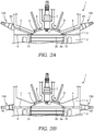
- the engine 1 includes a cylinder 2a formed in a cylinder block 2, a piston 2b that reciprocates through the cylinder 2a, and a cylinder head 3 (see FIG. 2A ) that is attached to the cylinder block 2 in order to close a top portion of the cylinder 2a.
- a combustion chamber 4 is formed in the engine 1 by the cylinder 2a, the piston 2b, and the cylinder head 3.
- the engine 1 is a spark ignition type internal combustion engine that obtains power when the multipoint spark plug 100 ignites and burns a compressed air-fuel mixture in the combustion chamber 4 together with a spark plug 7.
- the spark plug 7 is provided in an upper portion of the combustion chamber 4, and the multipoint spark plug 100 is provided in a position removed from the spark plug 7.
- the engine 1 includes a pair of insertion holes 5 into which the multipoint spark plug 100 is inserted.
- the insertion holes 5 are formed in the cylinder head 3.
- the insertion holes 5 may be formed in a head gasket 6 provided between the cylinder block 2 and the cylinder head 3.
- the insertion holes 5 may be formed in the cylinder block 2. In other words, the insertion holes 5 are formed in any part of the engine 1 into which the multipoint spark plug 100 can be inserted.
- the insertion holes 5 are through holes having a flattened, rounded-edge rectangular shape that corresponds to a main body portion 10 of the multipoint spark plug 100.
- the insertion holes 5 are respectively formed in positions removed from the spark plug 7 on an intake valve 8 side and an exhaust valve 9 side of the combustion chamber 4 (in a lower end portion of the combustion chamber 4). Accordingly, one multipoint spark plug 100 is provided in a position removed from the spark plug 7 on the opposite side of the intake valve 8 thereto, and one multipoint spark plug 100 is provided in a position removed from the spark plug 7 on the opposite side of the exhaust valve 9 thereto.
- ignition is performed by the multipoint spark plugs 100 in addition to the spark plug 7, and therefore a flame motion can be generated during combustion. Hence, fast combustion can be realized without providing a squish area, and as a result, cooling loss can be reduced.
- the present invention is not limited to this configuration, and instead, the insertion holes 5 may be formed away from the spark plug 7 in locations within the combustion chamber 4 where the temperature of the air-fuel mixture is low, or in other words locations where knocking is more likely to occur. Further, the insertion hole 5 may be formed in a single location in the combustion chamber 4, or in a plurality of three or more locations. By forming the insertion holes 5 in accordance with the shape of the combustion chamber 4 in this manner, a desired number of multipoint spark plugs 100 can be provided.
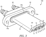
- the multipoint spark plug 100 includes the main body portion 10 that is formed in a flattened shape and inserted into the insertion hole 5 in the cylinder head 3 so that a tip end portion 11 thereof opposes the combustion chamber 4, a pair of side electrodes 12 provided via a gap in a lengthwise direction of the tip end portion 11, intermediate electrodes 13 provided in the gap between the pair of side electrodes 12 so as to form a plurality of ignition gaps 14 in the lengthwise direction of the tip end portion 11, insulators 15 serving as electrode holding portions that project into the combustion chamber 4 from the tip end portion 11 and hold the side electrodes 12 and intermediate electrodes 13, and a flange portion 20 that is formed to be larger than the main body portion 10 and serves as an attachment portion that is attached to the cylinder head 3.
- the main body portion 10 has a rounded-edge rectangle-shaped cross-section corresponding to the shape of the insertion hole 5, and is formed at a length corresponding to the insertion hole 5.
- the main body portion 10 is formed from a metal such as aluminum.
- a metal gasket 16 is wound around the main body portion 10 as a first sealing material that closes a gap between the main body portion 10 and the insertion hole 5.
- the metal gasket 16 will be described in further detail below.
- the tip end portion 11 is formed in an identical shape to an inner periphery of the combustion chamber 4, and forms a part of the inner periphery of the combustion chamber 4. More specifically, the tip end portion 11 is formed in a spherical surface shape that has an identical radius to the hemispherical combustion chamber 4 when the multipoint spark plug 100 is attached to the cylinder head 3 in which the hemispherical combustion chamber 4 is provided. Further, the tip end portion 11 is formed in a curved surface shape that has an identical radius to an inner periphery of the cylinder 2a when the multipoint spark plug 100 is attached to the head gasket 6.
- the side electrodes 12 are held on the main body portion 10 via the insulators 15.
- the side electrodes 12 project further into the combustion chamber 4 from the insulators 15.
- the side electrodes 12 are formed so as to project from the tip end portion 11 in an L shape.
- One of the side electrodes 12 (a first side electrode 12) penetrates the main body portion 10 and the flange portion 20 so as to extend to an input terminal 22, to be described below.
- the other side electrode 12 (a second side electrode 12) penetrates the main body portion 10 and the flange portion 20 similarly so as to extend to a connection terminal 23, to be described below.
- the pair of side electrodes 12 are provided so that respective tip ends thereof face each other.
- An ignition current from an ignition coil (not shown) is input into the first side electrode 12 via the input terminal 22.
- the intermediate electrodes 13 are provided in a pair and disposed between the pair of mutually opposing side electrodes 12.
- the intermediate electrodes 13 are held on the main body portion 10 via the insulator 15.
- the intermediate electrodes 13 project further into the combustion chamber 4 from the insulator 15.
- the intermediate electrodes 13 do not penetrate the main body portion 10. Instead, the intermediate electrodes 13 are held on the main body portion 10 by being inserted partially therein.
- the intermediate electrodes 13 are disposed in a straight line so as to form three ignition gaps 14 at equal intervals between the pair of mutually opposing side electrodes 12.
- the intermediate electrode 13 may be provided singly, or in a plurality of three or more.
- the number of intermediate electrodes 13 may be set as desired in accordance with a lengthwise direction dimension of the tip end portion 11 of the main body portion 10, a designed number of ignition gaps 14, and so on.
- the intermediate electrodes 13 are formed so as to project from the tip end portion 11 in a T shape. In so doing, the ignition current input into the first side electrode 12 from the ignition coil can pass through the ignition gaps 14 in a straight line and flow into the second side electrode 12. As a result, sparks can be generated reliably in the ignition gaps 14.
- the insulators 15 insulate the side electrodes 12 and the intermediate electrodes 13 from the main body portion 10.
- the insulators 15 that hold the side electrodes 12 project partially from the tip end portion 11, and are formed to be long enough to penetrate the main body portion 10 and the flange portion 20.
- the insulator 15 that holds the intermediate electrodes 13 projects partially from the tip end portion 11, and is formed at a size enabling a part thereof to be inserted into the interior of the main body portion 10.
- each insulator 15 includes a bottom surface 15b formed so as to be recessed from a tip end surface 15a in order to hold outer peripheries of the side electrodes 12 and intermediate electrodes 13, and curved surface portions 15c that connect the bottom surface 15b to the tip end surface 15a smoothly, and are formed in a curved surface shape that moves gradually further away from the side electrodes 12 and intermediate electrodes 13 from the bottom surface 15b toward the tip end surface 15a.
- the insulators 15 are formed from a material having an insulating property, such as a ceramic.
- a path from the side electrodes 12 and intermediate electrodes 13 to the outer periphery of the main body portion 10 is longer than in a case where the bottom surface 15b is not formed so as to be recessed from the tip end portion 15a.
- a situation in which the side electrodes 12 and intermediate electrodes 13 short-circuit to the cylinder head 3 via the outer periphery of the main body portion 10 can be prevented from occurring.
- the metal gasket 16 is wound around the outer periphery of the main body portion 10 of the multipoint spark plug 100 when the main body portion 10 is to be inserted into the insertion hole 5. As a result, the metal gasket 16 seals the gap between the main body portion 10 and the insertion hole 5 when the multipoint spark plug 100 is attached.
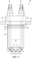
- the metal gasket 16 is formed from a metal material. As shown in FIG. 4 , the metal gasket 16 includes a bead portion 16a that projects around an outer periphery thereof.
- the bead portion 16a projects in an annular shape from substantially the center of the metal gasket 16 toward an outer periphery thereof.
- the flange portion 20 is formed around the entire periphery of the main body portion 10 so as to project from the main body portion 10 toward the outer periphery thereof.
- the flange portion 20 is formed integrally with the main body portion 10 from a metal such as aluminum.
- the flange portion 20 includes a pair of fastening holes 25a.
- the flange portion 20 is fastened to an outer surface of the cylinder head 3 by a pair of bolts 25 inserted into the fastening holes 25a.
- An O-ring 21 is provided on the flange portion 20 as a second sealing material that seals a contact surface between the flange portion 20 and the cylinder head 3.
- the O-ring 21 is inserted into an O-ring groove 20a formed in an annular shape in a surface of the flange portion 20 that opposes the main body portion 10.
- the O-ring 21 is formed from a rubber material.
- the O-ring 21 is compressed between the flange portion 20 and the cylinder head 3 by a fastening force of the bolts 25. Accordingly, when the flange portion 20 is fastened to the cylinder head 3, the O-ring 21 seals the gap between the main body portion 10 and the insertion hole 5.
- the gap between the main body portion 10 of the multipoint plug 100 and the insertion hole 5 of the engine 1 is sealed doubly by the metal gasket 16 and the O-ring 21, but the gap may be sealed by only one of the metal gasket 16 and the O-ring 21.
- the flange portion 20 includes the input terminal 22, which is connected to the first side electrode 12 and receives the ignition current from the ignition coil, and the connection terminal 23, which is connected to the second side electrode 12 and to the input terminal 22 of the other multipoint spark plug 100.
- the pair of the multipoint spark plugs 100 provided in the single combustion chamber 4 can be connected in series via a plug cord (not shown) so as to perform ignition simultaneously.
- the spark plug 7 can be connected in series to the ends of the pair of multipoint spark plugs 100 via a plug cord (not shown) so as to perform ignition simultaneously therewith.
- an earth electrode 7a (see FIG. 2A ) of the spark plug 7 is earthed by being brought into contact with the cylinder head 3.
- the pair of bolts 25 are removed and the main body portion 10 is withdrawn from the insertion hole 5 in the engine 1.
- the metal gasket 16 is wound around the main body portion 10 of the new multipoint spark plug 100, and the O-ring 21 is inserted into the O-ring groove 20a.
- the new multipoint spark plug 100 is then inserted into the insertion hole 5 in the engine 1.
- the pair of bolts 25 are inserted into the fastening holes 25a and fastened, whereby exchange of the multipoint spark plug 100 is complete.
- the multipoint spark plug 100 can be exchanged simply by withdrawing the multipoint spark plug 100 from the insertion hole 5 in the engine 1 and inserting the new multipoint spark plug 100, and as a result, the multipoint spark plug 100 can be exchanged easily.
- the multipoint spark plug 100 in contrast to the spark plug 7, does not have to be rotated so as to be screwed to a female screw formed in the cylinder head 3, and therefore the side electrodes 12 and intermediate electrodes 13 can be disposed reliably in prescribed positions within the combustion chamber 4. Hence, the positions of the ignition gaps 14 do not change even when the multipoint spark plug 100 is exchanged, and as a result, the air-fuel mixture can be burned as designed.
- the plurality of ignition gaps 14 are formed to extend in the lengthwise direction along the tip end portion 11 of the flattened main body portion 10, and therefore multipoint ignition can be achieved over a wide range.
- the flattened main body portion 10 is inserted into the insertion hole 5 in the engine 1 so that the tip end portion 11 thereof opposes the combustion chamber 4. Therefore, the multipoint spark plug 100 can be exchanged simply by withdrawing the multipoint spark plug 100 from the insertion hole 5 in the engine 1 and inserting the new multipoint spark plug 100.
- multipoint spark plug 100 and the engine 1 multipoint ignition can be achieved over a wide range, and the multipoint spark plug 100 can be exchanged easily.
- the multipoint spark plug 100 may be provided only in a position removed from the spark plug 7 on the opposite side of the exhaust valve 9 thereto. In this case, ignition is performed by the multipoint spark plug 100 in the vicinity of the exhaust valve 9, and therefore amounts of nitrogen oxide (NOx) and so on generated during combustion of the air-fuel mixture can be reduced.
- NOx nitrogen oxide
- the air-fuel mixture in the combustion chamber 4 is ignited by both spark plug 7 and the multipoint spark plugs 100, but the spark plug 7 may be omitted so that the multipoint spark plugs 100 are provided alone.
- an inner diameter (a bore diameter) of the combustion chamber 4 is comparatively small, for example, fast combustion can be realized in a similar manner to the above embodiment even when ignition is performed by the multipoint spark plugs 100 alone.
- the main body portion 10 and the flange portion 20 are formed integrally from a metal such as aluminum, and the insulators 15, which are formed from an insulating material such as a ceramic, are inserted therein.
- the main body portion 10 and the insulators 15 may be formed integrally from an insulating material such as a ceramic, and the flange portion 20 may be formed from a metal such as aluminum and attached thereto.
Landscapes
- Engineering & Computer Science (AREA)
- Chemical & Material Sciences (AREA)
- Combustion & Propulsion (AREA)
- Mechanical Engineering (AREA)
- General Engineering & Computer Science (AREA)
- Ignition Installations For Internal Combustion Engines (AREA)
- Cylinder Crankcases Of Internal Combustion Engines (AREA)
- Spark Plugs (AREA)
Claims (10)
- Mehrpunktzündkerze (100), die konfiguriert ist, ein Luft-Treibstoff-Gemisch in einer Brennkammer (4) eines Motors (1) zu zünden, umfassend:einen Hauptkörperabschnitt (10), der in einem Einbringloch (5) des Motors (1) derart eingebracht ist, dass ein vorderer Endabschnitt (11) desselben der Brennkammer (4) gegenüberliegt;ein Paar von Seitenelektroden (12), die über einen Spalt in eine Längsrichtung des vorderen Endabschnitts (11) bereitgestellt sind; undmindestens eine Zwischenelektrode (13), die in dem Spalt zwischen dem Seitenelektrodenpaar (12) derart bereitgestellt ist, dass eine Vielzahl Zündspalte (14) in Längsrichtung des vorderen Endabschnitts (11) ausgebildet ist,dadurch gekennzeichnet, dass der Hauptkörperabschnitt (10) in einer abgeflachten Form ausgebildet ist.
- Mehrpunktzündkerze (100) gemäß Anspruch 1, ferner umfassend Elektrodenhalteabschnitte (15), die in die Brennkammer (4) vom vorderen Endabschnitt (11) hineinragen, wobei die Elektrodenhalteabschnitte (15) die Seitenelektroden (12) und die Zwischenelektrode (13) halten,
wobei die Seitenelektroden (12) und die Zwischenelektrode (13) von den Elektrodenhalteabschnitten (15) weiter in die Brennkammer (4) hineinragen. - Mehrpunktzündkerze (100) gemäß Anspruch 2, wobei die Elektrodenhalteabschnitte (15) die Seitenelektroden (12) und die Zwischenelektrode (13) vom Hauptkörperabschnitt (10) isolieren.
- Mehrpunktzündkerze (100) gemäß einem der Ansprüche 1 bis 3, wobei der vordere Endabschnitt (11) in einer zu einem Innenumfang der Brennkammer (4) identischen Form ausgebildet ist, um so einen Teil des Innenumfangs zu bilden.
- Mehrpunktzündkerze (100) gemäß einem der Ansprüche 1 bis 4, ferner umfassend:einen Eingangsanschluss (22), der mit einer der Seitenelektroden (12) verbunden ist, wobei der Eingangsanschluss (22) einen Zündstrom von einer Zündspule empfängt; undeinen Verbindungsanschluss (23), der mit der anderen Seitenelektrode (12) verbunden ist, wobei der Verbindungsanschluss (23) mit dem Eingangsanschluss (22) einer weiteren Mehrpunktzündkerze (100) verbunden ist.
- Mehrpunktzündungsmotor (1), umfassend die Mehrpunktzündkerze (100) gemäß Anspruch 1.
- Mehrpunktzündungsmotor (1) gemäß Anspruch 6, wobei die Mehrpunktzündkerze (100) an einer Stelle der Brennkammer (4) bereitgestellt ist, an der eine Temperatur eines Luft-Treibstoff-Gemisches niedrig ist.
- Mehrpunktzündungsmotor gemäß Anspruch 6 oder Anspruch 7, ferner umfassend eine Zündkerze (7), die in einem oberen Abschnitt der Brennkammer (4) bereitgestellt ist, um ein komprimiertes Luft-Treibstoff-Gemisch in der Brennkammer (4) zusammen mit der Mehrpunktzündkerze (100) zu zünden und zu verbrennen,
wobei die Mehrpunktzündkerze (100) in einer Position bereitgestellt ist, die von der Zündkerze (7) entfernt angeordnet ist. - Mehrpunktzündungsmotor (1) gemäß Anspruch 8, wobei die Mehrpunktzündkerze (100) jeweils in einer von der Zündkerze (7) entfernten Position, auf einer dazu gegenüberliegenden Seite eines Ansaugventils (8), und einer von der Zündkerze (7) entfernten Position, auf einer dazu gegenüberliegenden Seite eines Auslassventils (9), bereitgestellt ist.
- Mehrpunktzündungsmotor (1) gemäß Anspruch 8, wobei die Mehrpunktzündkerze (100) lediglich in einer von der Zündkerze (7) entfernten Position, auf einer dazu gegenüberliegenden Seite eines Auslassventils (9), bereitgestellt ist.
Applications Claiming Priority (3)
| Application Number | Priority Date | Filing Date | Title |
|---|---|---|---|
| JP2016022983A JP6007345B1 (ja) | 2016-02-09 | 2016-02-09 | 多点点火プラグ及び多点点火プラグの製造方法 |
| JP2016022982A JP6007344B1 (ja) | 2016-02-09 | 2016-02-09 | 多点点火プラグ |
| JP2016128127A JP6028955B1 (ja) | 2016-06-13 | 2016-06-13 | 多点点火エンジン |
Publications (2)
| Publication Number | Publication Date |
|---|---|
| EP3206270A1 EP3206270A1 (de) | 2017-08-16 |
| EP3206270B1 true EP3206270B1 (de) | 2019-10-16 |
Family
ID=57963109
Family Applications (1)
| Application Number | Title | Priority Date | Filing Date |
|---|---|---|---|
| EP17154586.6A Active EP3206270B1 (de) | 2016-02-09 | 2017-02-03 | Mehrpunktzündkerze und mehrpunktzündungsmotor |
Country Status (3)
| Country | Link |
|---|---|
| US (1) | US10054100B2 (de) |
| EP (1) | EP3206270B1 (de) |
| CN (1) | CN107046231B (de) |
Cited By (1)
| Publication number | Priority date | Publication date | Assignee | Title |
|---|---|---|---|---|
| US11784466B2 (en) * | 2021-09-09 | 2023-10-10 | Hyundai Motor Company | Multi-ignition coil control system |
Families Citing this family (4)
| Publication number | Priority date | Publication date | Assignee | Title |
|---|---|---|---|---|
| CN107394588A (zh) * | 2017-09-05 | 2017-11-24 | 赵国龙 | 多电极火花塞 |
| US11545816B2 (en) | 2020-11-04 | 2023-01-03 | Federal-Mogul Ignition Gmbh | Spark plug with multiple spark gaps |
| CN113565664A (zh) * | 2021-07-31 | 2021-10-29 | 涂启莲 | 集群火花塞点火系统 |
| US12577902B1 (en) | 2024-09-18 | 2026-03-17 | Saudi Arabian Oil Company | Electrically assisted pre-chamber ignition system |
Family Cites Families (25)
| Publication number | Priority date | Publication date | Assignee | Title |
|---|---|---|---|---|
| JPS57131868A (en) | 1981-02-10 | 1982-08-14 | Nippon Denso Co Ltd | Ignition apparatus for internal combustion engine |
| JPS58180775A (ja) | 1982-04-16 | 1983-10-22 | Toyota Motor Corp | 多点点火式内燃機関 |
| JPH0775192B2 (ja) | 1985-06-19 | 1995-08-09 | 日本特殊陶業株式会社 | 小型点火プラグ |
| US4841925A (en) * | 1986-12-22 | 1989-06-27 | Combustion Electromagnetics, Inc. | Enhanced flame ignition for hydrocarbon fuels |
| JP2512789B2 (ja) | 1988-10-12 | 1996-07-03 | 株式会社日立製作所 | エンジンの燃料制御装置 |
| JP2898376B2 (ja) | 1990-08-22 | 1999-05-31 | 株式会社東芝 | 高電子移動度トランジスタ |
| CN1037990C (zh) * | 1993-03-31 | 1998-04-08 | 牛程鹏 | 汽油机多点同步点火装置 |
| JPH10189212A (ja) * | 1995-11-15 | 1998-07-21 | Ngk Spark Plug Co Ltd | 多極スパークプラグ |
| JPH09219274A (ja) | 1995-12-06 | 1997-08-19 | Denso Corp | スパークプラグ |
| JP3269032B2 (ja) * | 1997-09-01 | 2002-03-25 | 日本特殊陶業株式会社 | スパークプラグ及びそれを用いた内燃機関用点火システム |
| US6495948B1 (en) * | 1998-03-02 | 2002-12-17 | Pyrotek Enterprises, Inc. | Spark plug |
| US6617706B2 (en) * | 1998-11-09 | 2003-09-09 | Ngk Spark Plug Co., Ltd. | Ignition system |
| JP3211820B2 (ja) | 1998-12-04 | 2001-09-25 | 株式会社デンソー | 内燃機関用スパークプラグ |
| DE19911023C2 (de) * | 1999-03-12 | 2001-07-05 | Daimler Chrysler Ag | Direkteinspritzende Otto-Brennkraftmaschine |
| JP4187343B2 (ja) * | 1999-03-26 | 2008-11-26 | 日本特殊陶業株式会社 | セミ沿面放電型内燃機関用スパークプラグ |
| JP3859410B2 (ja) * | 1999-11-16 | 2006-12-20 | 日本特殊陶業株式会社 | スパークプラグ |
| JP3843217B2 (ja) * | 2001-04-25 | 2006-11-08 | 靖雄 磯野 | 内燃機関用点火装置および燃料室内に充填された燃料への点火方法 |
| JP2006049206A (ja) | 2004-08-06 | 2006-02-16 | Denso Corp | 内燃機関用スパークプラグ |
| JP2006114476A (ja) * | 2004-09-14 | 2006-04-27 | Denso Corp | 内燃機関用のスパークプラグ |
| CN101033725B (zh) * | 2006-03-07 | 2011-06-29 | 米亚马株式会社 | 多点点火发动机 |
| JP2008218204A (ja) | 2007-03-05 | 2008-09-18 | Miyama Kk | 多点点火プラグ |
| JP4139847B1 (ja) | 2007-08-06 | 2008-08-27 | ミヤマ株式会社 | 多点点火装置 |
| JP4864065B2 (ja) * | 2008-11-05 | 2012-01-25 | 日本特殊陶業株式会社 | スパークプラグ |
| US9780534B2 (en) * | 2015-09-10 | 2017-10-03 | Laurian Petru Chirila | Multi-electrode spark plug |
| US9742160B1 (en) * | 2016-02-09 | 2017-08-22 | Miyama, Inc. | Multipoint spark plug and multipoint spark plug manufacturing method |
-
2017
- 2017-01-25 US US15/414,828 patent/US10054100B2/en active Active
- 2017-02-03 EP EP17154586.6A patent/EP3206270B1/de active Active
- 2017-02-09 CN CN201710071477.2A patent/CN107046231B/zh active Active
Non-Patent Citations (1)
| Title |
|---|
| None * |
Cited By (1)
| Publication number | Priority date | Publication date | Assignee | Title |
|---|---|---|---|---|
| US11784466B2 (en) * | 2021-09-09 | 2023-10-10 | Hyundai Motor Company | Multi-ignition coil control system |
Also Published As
| Publication number | Publication date |
|---|---|
| CN107046231B (zh) | 2020-09-01 |
| EP3206270A1 (de) | 2017-08-16 |
| US20170226982A1 (en) | 2017-08-10 |
| US10054100B2 (en) | 2018-08-21 |
| CN107046231A (zh) | 2017-08-15 |
Similar Documents
| Publication | Publication Date | Title |
|---|---|---|
| EP3206270B1 (de) | Mehrpunktzündkerze und mehrpunktzündungsmotor | |
| US20190376441A1 (en) | Pre-Chamber Spark Plug | |
| US9929539B2 (en) | Prechamber spark plug | |
| US10714904B2 (en) | Spark plug | |
| EP3206269B1 (de) | Mehrpunktzündkerze und mehrpunktzündkerzenherstellungsverfahren | |
| CN109424420B (zh) | 火花塞 | |
| US8432092B2 (en) | Spark plug | |
| US11552456B1 (en) | Pre-chamber spark plug | |
| JP6007344B1 (ja) | 多点点火プラグ | |
| EP3366915B1 (de) | Mehrpunktzündungsvorrichtung und mehrpunktzündungsmotor | |
| JP6645168B2 (ja) | 点火プラグ | |
| JP6044863B1 (ja) | 多点点火プラグ | |
| JP6028955B1 (ja) | 多点点火エンジン | |
| EP3366916B1 (de) | Mehrpunktzündungsvorrichtung und mehrpunktzündungsmotor | |
| KR100588074B1 (ko) | 내연기관용 점화플러그 | |
| JP6007345B1 (ja) | 多点点火プラグ及び多点点火プラグの製造方法 | |
| US10063037B2 (en) | Spark plug | |
| KR20190127555A (ko) | 내연 기관용 점화 플러그 | |
| JP2019197717A (ja) | 多点点火装置及び多点点火エンジン |
Legal Events
| Date | Code | Title | Description |
|---|---|---|---|
| PUAI | Public reference made under article 153(3) epc to a published international application that has entered the european phase |
Free format text: ORIGINAL CODE: 0009012 |
|
| STAA | Information on the status of an ep patent application or granted ep patent |
Free format text: STATUS: THE APPLICATION HAS BEEN PUBLISHED |
|
| AK | Designated contracting states |
Kind code of ref document: A1 Designated state(s): AL AT BE BG CH CY CZ DE DK EE ES FI FR GB GR HR HU IE IS IT LI LT LU LV MC MK MT NL NO PL PT RO RS SE SI SK SM TR |
|
| AX | Request for extension of the european patent |
Extension state: BA ME |
|
| STAA | Information on the status of an ep patent application or granted ep patent |
Free format text: STATUS: REQUEST FOR EXAMINATION WAS MADE |
|
| 17P | Request for examination filed |
Effective date: 20180124 |
|
| RBV | Designated contracting states (corrected) |
Designated state(s): AL AT BE BG CH CY CZ DE DK EE ES FI FR GB GR HR HU IE IS IT LI LT LU LV MC MK MT NL NO PL PT RO RS SE SI SK SM TR |
|
| GRAJ | Information related to disapproval of communication of intention to grant by the applicant or resumption of examination proceedings by the epo deleted |
Free format text: ORIGINAL CODE: EPIDOSDIGR1 |
|
| GRAP | Despatch of communication of intention to grant a patent |
Free format text: ORIGINAL CODE: EPIDOSNIGR1 |
|
| GRAP | Despatch of communication of intention to grant a patent |
Free format text: ORIGINAL CODE: EPIDOSNIGR1 |
|
| STAA | Information on the status of an ep patent application or granted ep patent |
Free format text: STATUS: GRANT OF PATENT IS INTENDED |
|
| INTG | Intention to grant announced |
Effective date: 20190523 |
|
| INTG | Intention to grant announced |
Effective date: 20190603 |
|
| GRAS | Grant fee paid |
Free format text: ORIGINAL CODE: EPIDOSNIGR3 |
|
| RIN1 | Information on inventor provided before grant (corrected) |
Inventor name: MINAMI, KATSUAKI |
|
| GRAA | (expected) grant |
Free format text: ORIGINAL CODE: 0009210 |
|
| STAA | Information on the status of an ep patent application or granted ep patent |
Free format text: STATUS: THE PATENT HAS BEEN GRANTED |
|
| AK | Designated contracting states |
Kind code of ref document: B1 Designated state(s): AL AT BE BG CH CY CZ DE DK EE ES FI FR GB GR HR HU IE IS IT LI LT LU LV MC MK MT NL NO PL PT RO RS SE SI SK SM TR |
|
| REG | Reference to a national code |
Ref country code: GB Ref legal event code: FG4D |
|
| REG | Reference to a national code |
Ref country code: CH Ref legal event code: EP |
|
| REG | Reference to a national code |
Ref country code: DE Ref legal event code: R096 Ref document number: 602017007740 Country of ref document: DE |
|
| REG | Reference to a national code |
Ref country code: IE Ref legal event code: FG4D |
|
| REG | Reference to a national code |
Ref country code: AT Ref legal event code: REF Ref document number: 1192214 Country of ref document: AT Kind code of ref document: T Effective date: 20191115 |
|
| REG | Reference to a national code |
Ref country code: SE Ref legal event code: TRGR |
|
| REG | Reference to a national code |
Ref country code: NL Ref legal event code: MP Effective date: 20191016 |
|
| REG | Reference to a national code |
Ref country code: LT Ref legal event code: MG4D |
|
| PG25 | Lapsed in a contracting state [announced via postgrant information from national office to epo] |
Ref country code: LV Free format text: LAPSE BECAUSE OF FAILURE TO SUBMIT A TRANSLATION OF THE DESCRIPTION OR TO PAY THE FEE WITHIN THE PRESCRIBED TIME-LIMIT Effective date: 20191016 Ref country code: PT Free format text: LAPSE BECAUSE OF FAILURE TO SUBMIT A TRANSLATION OF THE DESCRIPTION OR TO PAY THE FEE WITHIN THE PRESCRIBED TIME-LIMIT Effective date: 20200217 Ref country code: FI Free format text: LAPSE BECAUSE OF FAILURE TO SUBMIT A TRANSLATION OF THE DESCRIPTION OR TO PAY THE FEE WITHIN THE PRESCRIBED TIME-LIMIT Effective date: 20191016 Ref country code: BG Free format text: LAPSE BECAUSE OF FAILURE TO SUBMIT A TRANSLATION OF THE DESCRIPTION OR TO PAY THE FEE WITHIN THE PRESCRIBED TIME-LIMIT Effective date: 20200116 Ref country code: NO Free format text: LAPSE BECAUSE OF FAILURE TO SUBMIT A TRANSLATION OF THE DESCRIPTION OR TO PAY THE FEE WITHIN THE PRESCRIBED TIME-LIMIT Effective date: 20200116 Ref country code: PL Free format text: LAPSE BECAUSE OF FAILURE TO SUBMIT A TRANSLATION OF THE DESCRIPTION OR TO PAY THE FEE WITHIN THE PRESCRIBED TIME-LIMIT Effective date: 20191016 Ref country code: NL Free format text: LAPSE BECAUSE OF FAILURE TO SUBMIT A TRANSLATION OF THE DESCRIPTION OR TO PAY THE FEE WITHIN THE PRESCRIBED TIME-LIMIT Effective date: 20191016 Ref country code: GR Free format text: LAPSE BECAUSE OF FAILURE TO SUBMIT A TRANSLATION OF THE DESCRIPTION OR TO PAY THE FEE WITHIN THE PRESCRIBED TIME-LIMIT Effective date: 20200117 Ref country code: LT Free format text: LAPSE BECAUSE OF FAILURE TO SUBMIT A TRANSLATION OF THE DESCRIPTION OR TO PAY THE FEE WITHIN THE PRESCRIBED TIME-LIMIT Effective date: 20191016 |
|
| PG25 | Lapsed in a contracting state [announced via postgrant information from national office to epo] |
Ref country code: RS Free format text: LAPSE BECAUSE OF FAILURE TO SUBMIT A TRANSLATION OF THE DESCRIPTION OR TO PAY THE FEE WITHIN THE PRESCRIBED TIME-LIMIT Effective date: 20191016 Ref country code: HR Free format text: LAPSE BECAUSE OF FAILURE TO SUBMIT A TRANSLATION OF THE DESCRIPTION OR TO PAY THE FEE WITHIN THE PRESCRIBED TIME-LIMIT Effective date: 20191016 Ref country code: IS Free format text: LAPSE BECAUSE OF FAILURE TO SUBMIT A TRANSLATION OF THE DESCRIPTION OR TO PAY THE FEE WITHIN THE PRESCRIBED TIME-LIMIT Effective date: 20200224 |
|
| PG25 | Lapsed in a contracting state [announced via postgrant information from national office to epo] |
Ref country code: AL Free format text: LAPSE BECAUSE OF FAILURE TO SUBMIT A TRANSLATION OF THE DESCRIPTION OR TO PAY THE FEE WITHIN THE PRESCRIBED TIME-LIMIT Effective date: 20191016 |
|
| REG | Reference to a national code |
Ref country code: DE Ref legal event code: R097 Ref document number: 602017007740 Country of ref document: DE |
|
| PG2D | Information on lapse in contracting state deleted |
Ref country code: IS |
|
| PG25 | Lapsed in a contracting state [announced via postgrant information from national office to epo] |
Ref country code: EE Free format text: LAPSE BECAUSE OF FAILURE TO SUBMIT A TRANSLATION OF THE DESCRIPTION OR TO PAY THE FEE WITHIN THE PRESCRIBED TIME-LIMIT Effective date: 20191016 Ref country code: CZ Free format text: LAPSE BECAUSE OF FAILURE TO SUBMIT A TRANSLATION OF THE DESCRIPTION OR TO PAY THE FEE WITHIN THE PRESCRIBED TIME-LIMIT Effective date: 20191016 Ref country code: RO Free format text: LAPSE BECAUSE OF FAILURE TO SUBMIT A TRANSLATION OF THE DESCRIPTION OR TO PAY THE FEE WITHIN THE PRESCRIBED TIME-LIMIT Effective date: 20191016 Ref country code: ES Free format text: LAPSE BECAUSE OF FAILURE TO SUBMIT A TRANSLATION OF THE DESCRIPTION OR TO PAY THE FEE WITHIN THE PRESCRIBED TIME-LIMIT Effective date: 20191016 Ref country code: DK Free format text: LAPSE BECAUSE OF FAILURE TO SUBMIT A TRANSLATION OF THE DESCRIPTION OR TO PAY THE FEE WITHIN THE PRESCRIBED TIME-LIMIT Effective date: 20191016 Ref country code: IS Free format text: LAPSE BECAUSE OF FAILURE TO SUBMIT A TRANSLATION OF THE DESCRIPTION OR TO PAY THE FEE WITHIN THE PRESCRIBED TIME-LIMIT Effective date: 20200216 |
|
| REG | Reference to a national code |
Ref country code: AT Ref legal event code: UEP Ref document number: 1192214 Country of ref document: AT Kind code of ref document: T Effective date: 20191016 |
|
| PLBE | No opposition filed within time limit |
Free format text: ORIGINAL CODE: 0009261 |
|
| STAA | Information on the status of an ep patent application or granted ep patent |
Free format text: STATUS: NO OPPOSITION FILED WITHIN TIME LIMIT |
|
| PG25 | Lapsed in a contracting state [announced via postgrant information from national office to epo] |
Ref country code: SK Free format text: LAPSE BECAUSE OF FAILURE TO SUBMIT A TRANSLATION OF THE DESCRIPTION OR TO PAY THE FEE WITHIN THE PRESCRIBED TIME-LIMIT Effective date: 20191016 Ref country code: SM Free format text: LAPSE BECAUSE OF FAILURE TO SUBMIT A TRANSLATION OF THE DESCRIPTION OR TO PAY THE FEE WITHIN THE PRESCRIBED TIME-LIMIT Effective date: 20191016 |
|
| 26N | No opposition filed |
Effective date: 20200717 |
|
| REG | Reference to a national code |
Ref country code: BE Ref legal event code: MM Effective date: 20200229 |
|
| PG25 | Lapsed in a contracting state [announced via postgrant information from national office to epo] |
Ref country code: MC Free format text: LAPSE BECAUSE OF FAILURE TO SUBMIT A TRANSLATION OF THE DESCRIPTION OR TO PAY THE FEE WITHIN THE PRESCRIBED TIME-LIMIT Effective date: 20191016 Ref country code: LU Free format text: LAPSE BECAUSE OF NON-PAYMENT OF DUE FEES Effective date: 20200203 |
|
| PG25 | Lapsed in a contracting state [announced via postgrant information from national office to epo] |
Ref country code: SI Free format text: LAPSE BECAUSE OF FAILURE TO SUBMIT A TRANSLATION OF THE DESCRIPTION OR TO PAY THE FEE WITHIN THE PRESCRIBED TIME-LIMIT Effective date: 20191016 |
|
| PG25 | Lapsed in a contracting state [announced via postgrant information from national office to epo] |
Ref country code: IE Free format text: LAPSE BECAUSE OF NON-PAYMENT OF DUE FEES Effective date: 20200203 |
|
| PG25 | Lapsed in a contracting state [announced via postgrant information from national office to epo] |
Ref country code: BE Free format text: LAPSE BECAUSE OF NON-PAYMENT OF DUE FEES Effective date: 20200229 |
|
| PG25 | Lapsed in a contracting state [announced via postgrant information from national office to epo] |
Ref country code: TR Free format text: LAPSE BECAUSE OF FAILURE TO SUBMIT A TRANSLATION OF THE DESCRIPTION OR TO PAY THE FEE WITHIN THE PRESCRIBED TIME-LIMIT Effective date: 20191016 Ref country code: MT Free format text: LAPSE BECAUSE OF FAILURE TO SUBMIT A TRANSLATION OF THE DESCRIPTION OR TO PAY THE FEE WITHIN THE PRESCRIBED TIME-LIMIT Effective date: 20191016 Ref country code: CY Free format text: LAPSE BECAUSE OF FAILURE TO SUBMIT A TRANSLATION OF THE DESCRIPTION OR TO PAY THE FEE WITHIN THE PRESCRIBED TIME-LIMIT Effective date: 20191016 |
|
| PG25 | Lapsed in a contracting state [announced via postgrant information from national office to epo] |
Ref country code: MK Free format text: LAPSE BECAUSE OF FAILURE TO SUBMIT A TRANSLATION OF THE DESCRIPTION OR TO PAY THE FEE WITHIN THE PRESCRIBED TIME-LIMIT Effective date: 20191016 |
|
| REG | Reference to a national code |
Ref country code: CH Ref legal event code: U11 Free format text: ST27 STATUS EVENT CODE: U-0-0-U10-U11 (AS PROVIDED BY THE NATIONAL OFFICE) Effective date: 20260301 |
|
| PGFP | Annual fee paid to national office [announced via postgrant information from national office to epo] |
Ref country code: SE Payment date: 20260218 Year of fee payment: 10 |
|
| PGFP | Annual fee paid to national office [announced via postgrant information from national office to epo] |
Ref country code: GB Payment date: 20260219 Year of fee payment: 10 |
|
| PGFP | Annual fee paid to national office [announced via postgrant information from national office to epo] |
Ref country code: DE Payment date: 20260218 Year of fee payment: 10 |
|
| PGFP | Annual fee paid to national office [announced via postgrant information from national office to epo] |
Ref country code: AT Payment date: 20260219 Year of fee payment: 10 |
|
| PGFP | Annual fee paid to national office [announced via postgrant information from national office to epo] |
Ref country code: IT Payment date: 20260224 Year of fee payment: 10 |
|
| PGFP | Annual fee paid to national office [announced via postgrant information from national office to epo] |
Ref country code: FR Payment date: 20260218 Year of fee payment: 10 |
|
| PGFP | Annual fee paid to national office [announced via postgrant information from national office to epo] |
Ref country code: CH Payment date: 20260301 Year of fee payment: 10 |