EP3206283A2 - Système de machine électrique, boîte de vitesses de véhicule automobile et procédé de production d'un système de machine électrique - Google Patents
Système de machine électrique, boîte de vitesses de véhicule automobile et procédé de production d'un système de machine électrique Download PDFInfo
- Publication number
- EP3206283A2 EP3206283A2 EP17157714.1A EP17157714A EP3206283A2 EP 3206283 A2 EP3206283 A2 EP 3206283A2 EP 17157714 A EP17157714 A EP 17157714A EP 3206283 A2 EP3206283 A2 EP 3206283A2
- Authority
- EP
- European Patent Office
- Prior art keywords
- housing
- rotor
- machine
- electrical machine
- bearing
- Prior art date
- Legal status (The legal status is an assumption and is not a legal conclusion. Google has not performed a legal analysis and makes no representation as to the accuracy of the status listed.)
- Withdrawn
Links
Images


Classifications
-
- H—ELECTRICITY
- H02—GENERATION; CONVERSION OR DISTRIBUTION OF ELECTRIC POWER
- H02K—DYNAMO-ELECTRIC MACHINES
- H02K7/00—Arrangements for handling mechanical energy structurally associated with dynamo-electric machines, e.g. structural association with mechanical driving motors or auxiliary dynamo-electric machines
- H02K7/08—Structural association with bearings
- H02K7/083—Structural association with bearings radially supporting the rotary shaft at both ends of the rotor
-
- H—ELECTRICITY
- H02—GENERATION; CONVERSION OR DISTRIBUTION OF ELECTRIC POWER
- H02K—DYNAMO-ELECTRIC MACHINES
- H02K5/00—Casings; Enclosures; Supports
- H02K5/04—Casings or enclosures characterised by the shape, form or construction thereof
- H02K5/16—Means for supporting bearings, e.g. insulating supports or means for fitting bearings in the bearing-shields
- H02K5/161—Means for supporting bearings, e.g. insulating supports or means for fitting bearings in the bearing-shields radially supporting the rotary shaft at both ends of the rotor
-
- B—PERFORMING OPERATIONS; TRANSPORTING
- B60—VEHICLES IN GENERAL
- B60K—ARRANGEMENT OR MOUNTING OF PROPULSION UNITS OR OF TRANSMISSIONS IN VEHICLES; ARRANGEMENT OR MOUNTING OF PLURAL DIVERSE PRIME-MOVERS IN VEHICLES; AUXILIARY DRIVES FOR VEHICLES; INSTRUMENTATION OR DASHBOARDS FOR VEHICLES; ARRANGEMENTS IN CONNECTION WITH COOLING, AIR INTAKE, GAS EXHAUST OR FUEL SUPPLY OF PROPULSION UNITS IN VEHICLES
- B60K1/00—Arrangement or mounting of electrical propulsion units
-
- F—MECHANICAL ENGINEERING; LIGHTING; HEATING; WEAPONS; BLASTING
- F16—ENGINEERING ELEMENTS AND UNITS; GENERAL MEASURES FOR PRODUCING AND MAINTAINING EFFECTIVE FUNCTIONING OF MACHINES OR INSTALLATIONS; THERMAL INSULATION IN GENERAL
- F16H—GEARING
- F16H57/00—General details of gearing
- F16H57/02—Gearboxes; Mounting gearing therein
- F16H57/021—Shaft support structures, e.g. partition walls, bearing eyes, casing walls or covers with bearings
-
- F—MECHANICAL ENGINEERING; LIGHTING; HEATING; WEAPONS; BLASTING
- F16—ENGINEERING ELEMENTS AND UNITS; GENERAL MEASURES FOR PRODUCING AND MAINTAINING EFFECTIVE FUNCTIONING OF MACHINES OR INSTALLATIONS; THERMAL INSULATION IN GENERAL
- F16H—GEARING
- F16H57/00—General details of gearing
- F16H57/02—Gearboxes; Mounting gearing therein
- F16H57/023—Mounting or installation of gears or shafts in the gearboxes, e.g. methods or means for assembly
-
- H—ELECTRICITY
- H02—GENERATION; CONVERSION OR DISTRIBUTION OF ELECTRIC POWER
- H02K—DYNAMO-ELECTRIC MACHINES
- H02K1/00—Details of the magnetic circuit
- H02K1/06—Details of the magnetic circuit characterised by the shape, form or construction
- H02K1/12—Stationary parts of the magnetic circuit
- H02K1/20—Stationary parts of the magnetic circuit with channels or ducts for flow of cooling medium
-
- H—ELECTRICITY
- H02—GENERATION; CONVERSION OR DISTRIBUTION OF ELECTRIC POWER
- H02K—DYNAMO-ELECTRIC MACHINES
- H02K15/00—Processes or apparatus specially adapted for manufacturing, assembling, maintaining or repairing of dynamo-electric machines
-
- H—ELECTRICITY
- H02—GENERATION; CONVERSION OR DISTRIBUTION OF ELECTRIC POWER
- H02K—DYNAMO-ELECTRIC MACHINES
- H02K15/00—Processes or apparatus specially adapted for manufacturing, assembling, maintaining or repairing of dynamo-electric machines
- H02K15/16—Centring rotors within the stators
-
- H—ELECTRICITY
- H02—GENERATION; CONVERSION OR DISTRIBUTION OF ELECTRIC POWER
- H02K—DYNAMO-ELECTRIC MACHINES
- H02K5/00—Casings; Enclosures; Supports
- H02K5/04—Casings or enclosures characterised by the shape, form or construction thereof
-
- H—ELECTRICITY
- H02—GENERATION; CONVERSION OR DISTRIBUTION OF ELECTRIC POWER
- H02K—DYNAMO-ELECTRIC MACHINES
- H02K5/00—Casings; Enclosures; Supports
- H02K5/04—Casings or enclosures characterised by the shape, form or construction thereof
- H02K5/16—Means for supporting bearings, e.g. insulating supports or means for fitting bearings in the bearing-shields
- H02K5/173—Means for supporting bearings, e.g. insulating supports or means for fitting bearings in the bearing-shields using bearings with rolling contact, e.g. ball bearings
- H02K5/1732—Means for supporting bearings, e.g. insulating supports or means for fitting bearings in the bearing-shields using bearings with rolling contact, e.g. ball bearings radially supporting the rotary shaft at both ends of the rotor
-
- H—ELECTRICITY
- H02—GENERATION; CONVERSION OR DISTRIBUTION OF ELECTRIC POWER
- H02K—DYNAMO-ELECTRIC MACHINES
- H02K7/00—Arrangements for handling mechanical energy structurally associated with dynamo-electric machines, e.g. structural association with mechanical driving motors or auxiliary dynamo-electric machines
- H02K7/10—Structural association with clutches, brakes, gears, pulleys or mechanical starters
- H02K7/1004—Structural association with clutches, brakes, gears, pulleys or mechanical starters with pulleys
- H02K7/1008—Structural association with clutches, brakes, gears, pulleys or mechanical starters with pulleys structurally associated with the machine rotor
-
- H—ELECTRICITY
- H02—GENERATION; CONVERSION OR DISTRIBUTION OF ELECTRIC POWER
- H02K—DYNAMO-ELECTRIC MACHINES
- H02K7/00—Arrangements for handling mechanical energy structurally associated with dynamo-electric machines, e.g. structural association with mechanical driving motors or auxiliary dynamo-electric machines
- H02K7/10—Structural association with clutches, brakes, gears, pulleys or mechanical starters
- H02K7/116—Structural association with clutches, brakes, gears, pulleys or mechanical starters with gears
-
- H—ELECTRICITY
- H02—GENERATION; CONVERSION OR DISTRIBUTION OF ELECTRIC POWER
- H02K—DYNAMO-ELECTRIC MACHINES
- H02K9/00—Arrangements for cooling or ventilating
- H02K9/19—Arrangements for cooling or ventilating for machines with closed casing and closed-circuit cooling using a liquid cooling medium, e.g. oil
-
- B—PERFORMING OPERATIONS; TRANSPORTING
- B60—VEHICLES IN GENERAL
- B60K—ARRANGEMENT OR MOUNTING OF PROPULSION UNITS OR OF TRANSMISSIONS IN VEHICLES; ARRANGEMENT OR MOUNTING OF PLURAL DIVERSE PRIME-MOVERS IN VEHICLES; AUXILIARY DRIVES FOR VEHICLES; INSTRUMENTATION OR DASHBOARDS FOR VEHICLES; ARRANGEMENTS IN CONNECTION WITH COOLING, AIR INTAKE, GAS EXHAUST OR FUEL SUPPLY OF PROPULSION UNITS IN VEHICLES
- B60K1/00—Arrangement or mounting of electrical propulsion units
- B60K2001/001—Arrangement or mounting of electrical propulsion units one motor mounted on a propulsion axle for rotating right and left wheels of this axle
-
- F—MECHANICAL ENGINEERING; LIGHTING; HEATING; WEAPONS; BLASTING
- F16—ENGINEERING ELEMENTS AND UNITS; GENERAL MEASURES FOR PRODUCING AND MAINTAINING EFFECTIVE FUNCTIONING OF MACHINES OR INSTALLATIONS; THERMAL INSULATION IN GENERAL
- F16H—GEARING
- F16H57/00—General details of gearing
- F16H57/02—Gearboxes; Mounting gearing therein
- F16H2057/02034—Gearboxes combined or connected with electric machines
-
- H—ELECTRICITY
- H02—GENERATION; CONVERSION OR DISTRIBUTION OF ELECTRIC POWER
- H02K—DYNAMO-ELECTRIC MACHINES
- H02K2201/00—Specific aspects not provided for in the other groups of this subclass relating to the magnetic circuits
- H02K2201/03—Machines characterised by aspects of the air-gap between rotor and stator
-
- H—ELECTRICITY
- H02—GENERATION; CONVERSION OR DISTRIBUTION OF ELECTRIC POWER
- H02K—DYNAMO-ELECTRIC MACHINES
- H02K2213/00—Specific aspects, not otherwise provided for and not covered by codes H02K2201/00 - H02K2211/00
- H02K2213/06—Machines characterised by the presence of fail safe, back up, redundant or other similar emergency arrangements
-
- H—ELECTRICITY
- H02—GENERATION; CONVERSION OR DISTRIBUTION OF ELECTRIC POWER
- H02K—DYNAMO-ELECTRIC MACHINES
- H02K5/00—Casings; Enclosures; Supports
- H02K5/04—Casings or enclosures characterised by the shape, form or construction thereof
- H02K5/15—Mounting arrangements for bearing-shields or end plates
-
- H—ELECTRICITY
- H02—GENERATION; CONVERSION OR DISTRIBUTION OF ELECTRIC POWER
- H02K—DYNAMO-ELECTRIC MACHINES
- H02K7/00—Arrangements for handling mechanical energy structurally associated with dynamo-electric machines, e.g. structural association with mechanical driving motors or auxiliary dynamo-electric machines
- H02K7/006—Structural association of a motor or generator with the drive train of a motor vehicle
Definitions
- the present invention relates to an electrical machine assembly for a motor vehicle powertrain, comprising a machine housing attachable to a power train housing, having a stator fixed with respect to the machine housing, having a rotor mounted concentrically with the stator within the machine housing, and a rotor axis, wherein between the stator and the rotor, an air gap is defined.
- the present invention relates to a motor vehicle transmission with a transmission housing, within which an electrical machine assembly is set.
- the present invention relates to a method for producing such an electrical machine arrangement.
- Electrical machines are suitable as drive machines for motor vehicles, for example in pure electric vehicles or even in motor vehicles with hybrid powertrain.
- motor vehicles with hybrid powertrain an internal combustion engine is provided as a drive motor, which is connected in a conventional manner via a transmission with at least one driven axle.
- the layout within the motor vehicle is largely predetermined.
- the electric machine can be arranged coaxially with the crankshaft of the internal combustion engine.
- the electric machine has its own machine housing, within which a rotor is rotatably mounted, as a rule via two pivot bearings such as roller bearings.
- the machine housing must be designed comparatively stable in this embodiment.
- the electric machine within the transmission housing in a hybrid drive train.
- the electric machine has no "own" machine housing, but a portion of the gear housing is formed so that it simulates a machine housing.
- a rotor becomes rotatable with respect to the transmission case stored.
- bearing forces can be introduced directly into the transmission housing, which in any case must be made relatively stable.
- a certain disadvantage of this embodiment is that only through the installation of the stator and the rotor in the transmission, the proper operation of the electrical machine assembly can be checked.
- a late check of the functionality of the electric machine in the production of the hybrid drive train is disadvantageous, since if errors occur, the entire transmission may need to be dismantled.
- the document reveals DE 197 21 528 A1 an electrical machine and a method for mounting it to an aggregate, wherein the electric machine has a stator and a rotor.
- the electric machine does not have bearing means which rotatably fix the rotor relative to the stator and thereby define the axis of rotation of the rotor.
- the electric machine has means for temporarily setting the position of the rotor relative to the stator. In this way, the rotor can be fixed axially, radially and in the circumferential direction relative to the stator. After assembly of the rotor to a gear shaft and after fixing the stator to a housing, the fixing means must be loosened, the rotor being displaced axially relative to the stator for this purpose.
- an object of the invention to provide an improved electrical machine assembly, an improved motor vehicle transmission and an improved method for producing an electrical machine assembly, wherein preferably an electric machine before assembly in a transmission housing with respect to the electrical functions is testable and / or the electrical machine assembly can be preferably carried out inexpensively and / or with low weight.
- the machine housing has a second bearing seat for a secondary shaft, which is offset parallel to a longitudinal axis of the rotor.
- the connection between the electrical machine assembly and the transmission is preferably via a spur gear.
- the spur gear assembly preferably includes a drive pinion, which is fixed coaxially to the rotor at a portion of the rotor in the form of the machine drive shaft, and a gear of the transmission, such as a loose wheel, which is associated with a gear stage of the transmission. It is particularly advantageous if between the gear of the transmission and the machine drive pinion another gear is provided, which is preferably fixed to a secondary shaft.
- the secondary shaft is in this case preferably rotatably supported by the machine housing and the other preferably via the transmission housing.
- the machine housing is provided from the outset so that a secondary shaft, on which such an intermediate wheel is fixed, can be stored at one axial end on the machine housing.
- the second bearing seat is formed on a second wall portion of the machine housing, wherein on the second wall portion and the housing bearing portion is formed.
- the second wall section is preferably designed as a bearing plate, by means of which the electric machine can be fixed in the gear housing.
- the second wall portion may have a peripheral flange portion, by means of which such a definition can be realized for example by screws.
- the second bearing seat on the second wall section of the machine housing is preferably accessible from outside the machine housing.
- the pivot bearing, which is preferably used in the second bearing seat, is preferably a rolling bearing.
- a first gear is mounted on a second rotor end portion, wherein on the secondary shaft, a second gear is mounted, which is in engagement with the first gear.
- the second rotor end section is preferably that section of the rotor which extends out of the machine housing.
- the second gear is preferably an intermediate gear of the type described above.
- the rotor has a first axial rotor end portion which is rotatably supported via a first pivot bearing with respect to the machine housing, wherein the first pivot bearing a first bearing seat of a first wall portion of the machine housing is set and wherein the first wall portion of the machine housing is further configured so that from the rotor via the first pivot bearing in the first wall portion introduced radial forces can be transmitted to the drive train housing when the machine housing fixed to the drive train housing is.
- bearing forces which are introduced into the first wall section via the first rotary bearing are introduced directly into the transmission housing.
- the first wall section of the machine housing can therefore be designed so that it does not have to transmit high radial forces. Consequently, the machine housing can be realized with a light weight overall.
- the machine housing in this case has a second wall portion on which the housing bearing portion is formed, wherein the second wall portion may be formed, for example, as a stable bearing plate.
- a cylinder portion of the machine housing between the wall portions and the first wall portion may preferably be integrally formed. Since the cylinder section and the first wall section do not have to transmit high forces, for example, this part of the machine housing may be made of a thin material such as a sheet metal.
- the first wall section has an annular web which can be inserted into an annular web receptacle of the drive train housing.
- the ring land and the ring land receiving are preferably formed coaxially with the first bearing seat.
- the annular web is preferably arranged in the axial direction overlapping or adjacent to the first bearing seat of the first wall portion of the machine housing.
- the rotor has a rotor bearing portion which is rotatably supported with radial play with respect to a housing bearing portion of the machine housing, wherein the radial clearance is smaller than the air gap between the rotor and stator.
- the electrical machine assembly it is possible to test these before assembly on a motor vehicle powertrain for their functionality, in particular in electrical terms.
- the measure to store a rotor bearing portion directly rotatable in a housing bearing portion of the machine housing in the radial direction, it is possible in a simple manner to connect the rotor, for example in a test environment to a load.
- the test environment is preferably designed such that suitable machine bearings are provided for the rotor. If the electrical machine arrangement is not yet in operation, it is avoided that the rotor contacts the stator. This could be possible in particular if the rotor is magnetized, in particular if on the rotor Permanent magnets are fixed.
- the radial bearing of the rotor bearing portion on the housing bearing portion thus represents a kind of "transport safety", which guides the rotor within narrow limits with respect to the machine housing and with respect to the stator.
- the rotor can have a rotor bearing section which is formed, for example, in the region of an axial rotor end section. In this case, at the other axial end portion, a bearing of the rotor on the machine housing via a rotary bearing, such as a rolling bearing.
- the rotor it is possible for the rotor to each have a rotor bearing section in the region of two opposite axial rotor end sections, in which case the machine housing could correspondingly have two associated housing bearing sections.
- the machine housing is preferably constructed so that it can be fixed within the drive train housing, in particular in the interior of a transmission housing.
- the stator is preferably fixed within the machine housing.
- the rotor is rotatably supported within the machine housing, but is preferably fixed with respect to its axial position with respect to the machine housing, so that in the electrical machine assembly relative movements between the stator and the rotor in the axial direction can be excluded.
- the air gap between stator and rotor is a nominal size, which is determined in particular for the operation of the electrical machine assembly (within very narrow tolerances).
- the radial clearance between the rotor bearing portion and the housing bearing portion is smaller than the air gap. In the preassembled state before installation on a drive train, the air gap can consequently still be variable by the radial clearance.
- the rotor is not rotationally fixed via the bearing on the machine housing, so it is freely rotatable in the circumferential direction with respect to the housing bearing portion.
- the housing bearing portion and the rotor bearing portion form a kind of centering device.
- the dimension of the air gap is in the radial direction at least twice as large as the radial clearance, in particular five times as large, and preferably at least ten times as large, but is preferably less than 100 times the radial clearance.
- the rotor is rotatably mounted in the region of at least one axial rotor end portion with respect to the transmission housing, in particular via a rotary bearing such as a rolling bearing.
- a rotary bearing such as a rolling bearing.
- This may in particular be that section at whose axial end the rotor bearing section is also formed.
- the overall system of electrical machine assembly and motor vehicle transmission can be optimized for low total weight. Furthermore, the motor vehicle transmission according to the invention can be mounted more easily. Because during assembly of the electrical machine assembly no special measures must be taken to ensure that the rotor is centered with respect to the stator. Such centering can already on the storage of the rotor bearing portion of the Housing bearing section of the machine housing can be realized. The assembly can therefore be done with relatively simple means. Consequently, rotor and stator can also be transported together within the machine housing for gearbox assembly.
- the rotor has a first axial rotor end portion which is rotatably supported via a first pivot bearing such as a rolling bearing with respect to the machine housing, wherein the Rotor having a second axial Rotorendabites, which extends in an axial direction at least partially from the machine housing and is adapted to be rotatably supported by means of a second pivot bearing such as a rolling bearing with respect to the drive train housing.
- the pre-assembled electrical machine arrangement thus provides that the rotor is preferably mounted exclusively via a first and a second pivot bearing, one of which is supported on the machine housing and of which the second is supported on the drive train housing.
- such an electrical machine assembly can be provided with a minimum number of bearings and the possibility to install a pinion in the region of a extending out of the machine housing portion of the rotor, which is helical. Because the axial forces occurring in this case can be preferably absorbed via the second pivot bearing.
- the gear is in particular fixed to the second axial Rotorendabites, which in this case forms a machine drive shaft.
- the gear is in particular a drive pinion of the electrical machine arrangement. It is particularly advantageous when the gear is arranged in the axial direction between the machine housing and a portion at which the second pivot bearing is fixed.
- the gear is arranged in the axial direction between the machine housing and a rotary bearing area of the second rotor end section.
- stator has a laminated core which is inserted into a cylinder section of the machine housing, wherein at least one cooling channel is formed between the laminated core and the cylinder section.
- the cooling channel is preferably formed directly by the laminated core and the cylinder portion, so that a direct cooling of the stator can be realized.
- the cooling fluid that can be passed through the cooling channel is preferably a fluid from the drive train, preferably transmission oil. However, if the cooling channel is sealed, a special cooling fluid, such as water, could be used.
- the cylinder portion of the machine housing may, as mentioned above, be formed integrally with a first wall portion.
- a plurality of cooling channels is formed, which are preferably distributed over the circumference, wherein a distributor device for supplying cooling fluid to the cooling channels in the region of a second wall portion of the machine housing is formed.
- the distributor device can be designed in this case from the mode of operation, as in the document DE 10 2012 022 452 A1 is described in its entirety reference is made here, at least as regards the cooling of the electrical machine assembly.
- the engine housing may be open to the interior of the drive train housing such as the motor vehicle transmission housing, for example, for bearings for pivot bearings of the rotor, the fluid from the transmission housing is used (transmission fluid such as ATF oil).
- transmission fluid such as ATF oil
- the machine housing is sealed off from the interior of the drive train housing.
- the sealed part may be, for example, a cooling area, by means of which the electric machine is cooled in order to be able to use a special cooling fluid in this way.
- the other rotor end portion is rotatably supported via a first pivot bearing such as a rolling bearing with respect to the machine housing and / or the rotor end portion is inserted into the housing bearing portion so that it partially out of the machine housing extends.
- a first pivot bearing such as a rolling bearing with respect to the machine housing and / or the rotor end portion is inserted into the housing bearing portion so that it partially out of the machine housing extends.
- the rotor shaft can be supported for their operation by means of two rolling bearings, in particular ball bearings.
- One of the bearings is preferably part of the electrical machine assembly, the other bearing is preferably not part of electrical machine assembly and is mounted only during installation in a transmission housing.
- An axial transfer point for transferring cooling fluid is preferably present on the machine housing, wherein the transfer point is preferably formed in the region of the second wall section.
- cooling fluid can be supplied to the distributor device, for example.
- a bearing of the rotor can also be done directly on the machine housing, so that bearing forces are introduced into the machine housing and no radial support of the machine housing in the drive train housing is necessary.
- the centering of the rotor bearing section on the housing bearing section can take place on a shaft section of the rotor, on the pinion, on the rotor core of the electric machine or on another component of the rotor shaft.
- the electrical machine assembly does not include an operating shaft bearing, especially if such centering is provided on both axial ends.
- the electrical machine assembly can be tested immediately after assembly at the manufacturer, wherein the electrical machine assembly is preferably mounted for this purpose in a receptacle which corresponds geometrically to the installation in the transmission housing. After the test, the electrical machine assembly can be transported because there is no danger that the rotor abuts the inside of the stator circumference by the centering device between the rotor bearing portion and the housing bearing portion. At least the first wall section and the cylinder section of the machine housing can be made thin-walled or particularly light due to the fact that only small bearing forces have to be absorbed, and can optionally also be formed with large-area recesses.
- the main function in particular of the cylinder section and the first wall section is the enclosure of the stator of the electric machine on the one hand and the centering of the shaft therein, as well as the conclusion of any Statorkühl Steinen, which are preferably formed on the outside of the stator.
- a powertrain for a motor vehicle is shown schematically and generally designated 10.
- the drive train 10 has a primary drive motor 12, for example in the form of an internal combustion engine. Further, the powertrain 10 includes a clutch assembly 14, which is connected on the input side to the drive motor 12, and the output side with a gear assembly 16. An output of the gear assembly 16 is connected to a differential 18, by means of which drive power to driven wheels 20L, 20R can be distributed.
- the gear assembly 16 includes a stepped transmission 24, which is designed in the present case as a countershaft transmission in Stirnradbauweise.
- the transmission 24 has a transmission housing 26, on which an input shaft arrangement 28 is mounted.
- the input shaft assembly 28 is connected to the clutch assembly 14.
- an output shaft assembly 30 is mounted on the transmission housing 26, which is connected to the differential 18.
- a plurality of gear sets 32 (of which in Fig. 1 for clarity, only one is shown) connect the input shaft assembly 28 with the output shaft assembly 30.
- the gear wheelsets 32 are switchable by means of respective clutches 34. More specifically, each gear set includes a fixed gear and a loose wheel engaged with each other.
- the idler gear is rotatably connected by means of an associated clutch 34 with a shaft to which the idler gear is rotatably mounted.
- the transmission 24 may be formed as a manual transmission, but may also be an automated transmission.
- the transmission 24 may be a dual-clutch transmission.
- the clutch assembly 14 includes two friction clutches
- the input shaft assembly 28 includes two input shafts, as known per se in the art.
- gear changes take place by overlapping the actuation of the clutches of the clutch assembly 14, so that gear changes can be carried out essentially without traction force intrusion.
- the drive train 10 includes an electrical machine assembly 40, wherein the electrical machine assembly 40 can be operated as a secondary drive motor, but can also be operated as a generator to load, for example, a non-illustrated battery of the drive train 10.
- the electric machine assembly 40 includes an electric machine 42 and a machine housing 44.
- the electric machine 42 has a stator 46 fixed in the machine housing 44.
- the electric machine 42 and consequently its stator 46 are arranged coaxially with a machine or rotor axis 48.
- the engine or rotor axis 48 is parallel to the input shaft assembly 28 and / or the output shaft assembly 30.
- the electric machine 42 further includes a rotor 50 which is coaxially disposed within the stator 46 and has a drive shaft 52 coaxial with the rotor axis 48.
- a drive pinion 54 is fixed on the drive shaft 52.
- the idler gear 54 is engaged with an intermediate gear 56.
- the idler gear 56 in turn, also engages a idler gear 58 of a gear set 32 of the transmission 24.
- drive power from the electric machine 42 can be transmitted through the engine Spur gear from drive pinion 54, idler 56 and idler gear 58 are guided to the output of the transmission 24.
- the electric machine 42 may in particular be connected to one of two partial transmissions of the transmission 24, if this is designed as a dual-clutch transmission, in particular with that partial transmission which is associated with the straight gear ratios and / or a reverse gear.
- the electric machine 42 can be assigned via a fixed gear ratio of an input shaft of the transmission 24, in particular the input shaft of one of the partial transmission of the transmission 24.
- the fixed gear ratio can be formed by suitable gears, even idler gears a gear teeth are possible.
- a wheelset 32, to which the electric machine 42 may be connected, may for example be associated with a middle gear, such as the gear 4.
- the idler gear 58 may be assigned to the gear 2, or even the gear 6, or even higher gear.
- the electric machine 42 with the other partial transmission, in this case also preferably a middle gear stage, for example the gear stage 3 or the gear stage 5.
- the electric machine 42 to the output of the transmission 24 connect the electric machine 42 thus the output of the transmission 24, ie speed proportional to the driving speed.
- Fig. 1 is also shown schematically that between the rotor 50 and the stator 46, an air gap 60 is present.
- the rotor 50 may include a plurality of permanent magnets on its outer periphery.
- the stator is provided in a conventional manner with electrical winding terminals to supply electrical power to the electric machine 42 or to remove therefrom.
- the electrical machine 42 may generally be any type of electrical machine, for example an asynchronous machine, a permanent or externally excited synchronous machine, a reluctance machine, etc.
- the engine case 44 includes a cylinder portion 64 that is coaxial with the electric machine 42 and is fixed externally around the stator 46, for example.
- the machine housing 44 further has a first wall section 66, which is arranged on the drive shaft 52 axially opposite side of the electric machine 42, and a second wall section 68, which faces the drive shaft 52.
- the first wall portion 66 and the cylinder portion 64 may be integrally formed with each other, for example, a thin material such as a metal sheet.
- the second wall portion 68 may be formed as a bearing plate, which is designed for receiving radial forces and for transferring such radial forces to the transmission housing 26.
- the second wall section 68 in the form of such a bearing plate may be connected to the transmission housing 26 for this purpose.
- the transmission housing 26 has a first housing wall 70, which is approximately parallel to the first wall portion 66 of the machine housing 44 and adjacent arranged for this purpose. Furthermore, the gear housing 26 includes a second housing wall 72 which is adjacent to the second wall portion 68 of the machine housing 44th
- the first wall portion 66 of the machine housing 44 has an annular ridge 74 which is aligned coaxially with the rotor axis 48.
- the first housing wall 70 has a Ringstegability 76, in which the annular web 74 can be axially inserted, such that in the annular web 74 initiated radial forces can be transmitted to the gear housing 26.
- the machine housing 44 further has, in the region of the second wall section 68, a machine housing flange 78, which is connected to a transmission housing flange 80 of the gear housing 26 via schematically indicated connecting means.
- the electrical machine assembly 40 may be axially inserted into the transmission housing 26 until the annular ridge 74 is received in the annular ridge receiver 76 and the machine housing flange 78 can be screwed or otherwise secured to the transmission housing flange 80.
- the transmission housing 26 may further include a machine housing receptacle 82 as shown in FIG Fig. 1 is indicated schematically. However, the transmission housing 26 need not completely surround the machine housing 44.
- the rotor 50 has a first axial rotor end portion 86 and an opposite second axial rotor end portion 88.
- the first axial Rotorendabites 86 is rotatably supported with respect to the machine housing 44 via a first pivot bearing 90 which is inserted into a first bearing seat 92 of the first wall portion 66 of the machine housing 44.
- the bearing seat 92 is preferably provided in axial overlap with the annular web 74 in order to be able to initiate radial forces introduced into the first rotary bearing 90 into the transmission housing.
- the annular web 74 and the first bearing seat 92 may also be adjacent to each other in the axial direction, so that the machine housing 44 initially radially transmitted forces are transmitted axially, to then be passed over the annular ridge 74 in the gear housing 26.
- the second axial rotor end portion 88 has a rotor bearing portion 98 rotatably supported with a radial clearance 99 rotatable relative to a housing bearing portion 96 with respect to the engine housing 44.
- the interaction between rotor bearing portion 98 and housing bearing portion 96 serves to center the rotor 50 in this area, ie in the region of the second axial Rotorendabiteses 88.
- the radial clearance 99 is significantly smaller than the radial air gap 60 between the rotor 50 and stator 46th
- the second axial rotor end portion 88 is also rotatably supported by a second pivot bearing 100 with respect to the second housing wall 72 of the transmission housing 26.
- the assembly of the second housing wall 72 and the bearing 100 with respect to the second axial Rotorendabites 88 preferably takes place only after the electrical machine assembly 40 has been mounted in the transmission housing 26.
- the drive pinion 54 is arranged in the axial direction between the rotor bearing portion 98 and the second pivot bearing 100.
- the first rotary bearing 90 and the second rotary bearing 100 may each be designed as a rolling bearing, in particular as a ball bearing.
- the second pivot bearing 100 preferably also serves to absorb axial forces that arise due to the tooth engagement.
- the intermediate 56 is fixed to a secondary shaft 104.
- the auxiliary shaft 104 is rotatably supported via a first auxiliary shaft bearing 106 with respect to the second wall section 68 of the machine housing 44.
- the second wall section 68 has a second bearing seat 108, which is formed eccentrically offset with respect to the rotor axis 48 on the second wall section 68.
- the auxiliary shaft 104 is rotatably mounted on the axially opposite side of the intermediate gear 56 by means of a second Mauwellenlagers 110 with respect to the transmission housing 26, in particular with respect to the second housing wall 72.
- a suitable bearing seat is preferably provided on the second housing wall 72.
- the first secondary shaft bearing 106 and the second secondary shaft bearing 110 may each be designed as rolling bearings, in particular as ball bearings, but may also be designed as sliding bearings.
- the auxiliary shaft 104 with the idler gear 56 fixed thereto can be provided with the pre-assembled electrical machine assembly 40 such that the second side wall portion 68 already has the first sub-shaft bearing 106 inserted therein and the sub-shaft 104 is inserted therein such that the idler 56 engages the idler shaft Drive pinion 54 is engaged.
- the assembly of the auxiliary shaft 104 with its bearings 106, 110 takes place only after the electrical machine assembly 40 has been mounted on the transmission housing 26.
- Fig. 2 shows a part of a drive train 10 with an electrical machine assembly 14, wherein the machine housing 44 is formed by a solid second wall portion 68 in the form of a bearing plate which is dimensioned so that, for example, an unsupported bearing seat for the secondary shaft 104 may be formed therein although this is in Fig. 2 not shown.
- the cylinder portion 64 and the first wall portion 66 are formed as thin portions and may be formed integrally with each other.
- the housing part which forms the cylinder section 64 and the first wall section 66 can be formed from a sheet metal pot.
- first rotary bearing 90 overlaps in the axial direction with the annular web receiver 76 in order to be able to initiate radial forces via the annular web 74 as directly as possible into the first housing wall 70 of the transmission housing 26.
- a bearing seat 112 is formed in the second housing wall 72.
- a fluid port 114 may be formed, can be supplied via the cooling fluid.
- the fluid connection 114 may be connected inside the machine housing 44 to a distributor device 116, which is designed, for example, in the manner of an annular channel. Introduced fluid can be passed through openings in the annular channel 116 to the adjacent winding heads 118 of windings of the stator 46 to cool them, because the winding heads 118 are in the operation of the electric machine 42 most thermally stressed.
- the stator 46 further has a laminated core 120 which bears directly against the inner circumference of the cylinder section 64.
- a plurality of cooling channels 122 are formed, which extend in the axial direction, such that via the fluid port 114 introduced fluid can flow through the cooling channels 122 to cool the stator 46.
- the fluid can escape from the cooling channels and be guided on the winding heads 118 provided there to also cool them.
- the cooling concept can correspond to the cooling concept contained in the documents DE 10 2012 022 452 A1 and 10 2012 022 453 A1 is disclosed, the disclosure of which is incorporated herein by reference.
- Fig. 3 shows a further embodiment of a drive train 10 with a detailed view of a second housing wall 72 and a second wall portion 68th
- the second axial rotor end section 88 which extends out of the second wall section 68 in the axial direction, is formed as a hollow shaft and is connected at its axial end to a cover cap 124, via the cooling fluid, which via an axial passage 126 is fed in the rotor end portion 66 to be able to lead to the second pivot bearing 100.
- the cap 124 may also be closed, although this is shown in FIG Fig. 3 not shown.
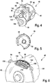
- FIG. 4 a further embodiment of an electrical machine arrangement is shown.
- the machine housing flange 78 may have a plurality of radially projecting eyes on which respective holes 130 are formed for the passage of screws or the like.
- an electrical plug connector via which the stator windings can be electrically contacted, is formed on the second wall section 68.
- Fig. 5 shows the electrical machine assembly 40 of Fig. 4 from the back, it being understood that the first wall section 66 shown here indeed has a ring land 74, but otherwise may be provided with openings and recesses in order to save weight.
- Fig. 6 shows a similar view as Fig. 4 but shows a detail in which the machine housing 44 is broken away.
- the stator 56 has a laminated core 120 with a plurality of axial cooling channels 122 which are formed between the cylinder section 64 and the laminated core 120.
- the distributor device 116 can be designed as an annular channel which is connected to the second wall section 68 and can be guided via the fluid toward the adjacent winding head 118.
Landscapes
- Engineering & Computer Science (AREA)
- Power Engineering (AREA)
- Mechanical Engineering (AREA)
- General Engineering & Computer Science (AREA)
- Manufacturing & Machinery (AREA)
- Chemical & Material Sciences (AREA)
- Combustion & Propulsion (AREA)
- Transportation (AREA)
- Connection Of Motors, Electrical Generators, Mechanical Devices, And The Like (AREA)
- Motor Or Generator Frames (AREA)
Priority Applications (1)
| Application Number | Priority Date | Filing Date | Title |
|---|---|---|---|
| EP17157714.1A EP3206283A3 (fr) | 2015-04-07 | 2015-04-07 | Système de machine électrique, boîte de vitesses de véhicule automobile et procédé de production d'un système de machine électrique |
Applications Claiming Priority (2)
| Application Number | Priority Date | Filing Date | Title |
|---|---|---|---|
| EP15162666.0A EP3079238B1 (fr) | 2015-04-07 | 2015-04-07 | Système de machine électrique et boîte de vitesses de véhicule automobile |
| EP17157714.1A EP3206283A3 (fr) | 2015-04-07 | 2015-04-07 | Système de machine électrique, boîte de vitesses de véhicule automobile et procédé de production d'un système de machine électrique |
Related Parent Applications (2)
| Application Number | Title | Priority Date | Filing Date |
|---|---|---|---|
| EP15162666.0A Division-Into EP3079238B1 (fr) | 2015-04-07 | 2015-04-07 | Système de machine électrique et boîte de vitesses de véhicule automobile |
| EP15162666.0A Division EP3079238B1 (fr) | 2015-04-07 | 2015-04-07 | Système de machine électrique et boîte de vitesses de véhicule automobile |
Publications (2)
| Publication Number | Publication Date |
|---|---|
| EP3206283A2 true EP3206283A2 (fr) | 2017-08-16 |
| EP3206283A3 EP3206283A3 (fr) | 2017-11-22 |
Family
ID=53002491
Family Applications (2)
| Application Number | Title | Priority Date | Filing Date |
|---|---|---|---|
| EP17157714.1A Withdrawn EP3206283A3 (fr) | 2015-04-07 | 2015-04-07 | Système de machine électrique, boîte de vitesses de véhicule automobile et procédé de production d'un système de machine électrique |
| EP15162666.0A Active EP3079238B1 (fr) | 2015-04-07 | 2015-04-07 | Système de machine électrique et boîte de vitesses de véhicule automobile |
Family Applications After (1)
| Application Number | Title | Priority Date | Filing Date |
|---|---|---|---|
| EP15162666.0A Active EP3079238B1 (fr) | 2015-04-07 | 2015-04-07 | Système de machine électrique et boîte de vitesses de véhicule automobile |
Country Status (3)
| Country | Link |
|---|---|
| US (1) | US10193415B2 (fr) |
| EP (2) | EP3206283A3 (fr) |
| CN (1) | CN106059171B (fr) |
Families Citing this family (15)
| Publication number | Priority date | Publication date | Assignee | Title |
|---|---|---|---|---|
| DE102017206641A1 (de) * | 2017-04-20 | 2018-10-25 | Bayerische Motoren Werke Aktiengesellschaft | Antriebseinheit und Kraftfahrzeug mit einer Antriebseinheit |
| DE102017213653A1 (de) * | 2017-08-07 | 2019-02-07 | Magna powertrain gmbh & co kg | Antriebsvorrichtung |
| DE102018001642A1 (de) | 2018-03-02 | 2019-09-05 | Daimler Ag | Antriebseinheit für ein Kraftfahrzeug, insbesondere für einen Kraftwagen |
| FR3080068B1 (fr) * | 2018-04-17 | 2020-09-04 | Valeo Embrayages | Systeme d'entrainement pour un vehicule automobile hybride et systeme de transmission comprenant un tel systeme d'entrainement |
| US11220171B2 (en) | 2018-05-30 | 2022-01-11 | Cecil A. Weeramantry | Drivetrain architecture |
| DE102018118069A1 (de) * | 2018-07-26 | 2020-01-30 | Dr. Ing. H.C. F. Porsche Aktiengesellschaft | Antriebsvorrichtung mit einem Elektromotor und einem Getriebe |
| KR102110048B1 (ko) * | 2018-10-16 | 2020-05-12 | (주)타마스 | 중공축 모터 |
| US11025133B2 (en) * | 2019-02-20 | 2021-06-01 | Dana Automotive Systems Group, Llc | Electric motor brake |
| DE102019117948B3 (de) * | 2019-07-03 | 2020-06-18 | Dr. Ing. H.C. F. Porsche Aktiengesellschaft | Elektrische Maschine |
| DE102020115138A1 (de) * | 2020-06-08 | 2021-12-09 | HELLA GmbH & Co. KGaA | Baugruppe für ein Fahrzeug und Fahrzeug |
| DE102020117262A1 (de) * | 2020-07-01 | 2022-01-05 | Schaeffler Technologies AG & Co. KG | Vorrichtung zur Bestimmung eines Drehmoments in einem Antriebsstrang eines zumindest teilweise elektrisch betriebenen Kraftfahrzeugs |
| FR3118910B1 (fr) * | 2021-01-18 | 2023-01-20 | Valeo Embrayages | Ensemble de transmission de véhicule et procédé d’assemblage d’un ensemble de transmission de véhicule |
| DE102021203495B3 (de) * | 2021-04-08 | 2022-03-24 | Magna Pt B.V. & Co. Kg | Hybrid-Getriebevorrichtung |
| CN115319445B (zh) * | 2021-05-10 | 2024-04-09 | 上汽通用汽车有限公司 | 定位导向装置 |
| FR3148546A1 (fr) * | 2023-05-11 | 2024-11-15 | Nidec Psa Emotors | Dispositif de propulsion pour véhicule automobile |
Citations (5)
| Publication number | Priority date | Publication date | Assignee | Title |
|---|---|---|---|---|
| DE19721528A1 (de) | 1997-05-22 | 1998-11-26 | Still Gmbh | Elektrische Maschine und Verfahren zur Montage der elektrischen Maschine an einem Aggregat |
| DE102012019971A1 (de) | 2012-10-08 | 2014-04-10 | Getrag Getriebe- Und Zahnradfabrik Hermann Hagenmeyer Gmbh & Cie Kg | Hybrid-Antriebsstrang für ein Kraftfahrzeug |
| DE102012022453A1 (de) | 2012-11-09 | 2014-05-15 | Getrag Getriebe- Und Zahnradfabrik Hermann Hagenmeyer Gmbh & Cie Kg | Elektrische Maschine und Kraftfahrzeug-Antriebsstrang |
| DE102012022452A1 (de) | 2012-11-09 | 2014-05-15 | Getrag Getriebe- Und Zahnradfabrik Hermann Hagenmeyer Gmbh & Cie Kg | Elektrische Maschine und Kraftfahrzeug-Antriebsstrang |
| DE102012024462A1 (de) | 2012-12-13 | 2014-06-18 | Karlheinz Kaden | Gerät, System und Verfahren zur Ermittlung von Geopositionen mit Wassertiefenangabe unter Einsatz eines mobilen Kommunikationsgerätes zwecks Verwertung in Datenbanken und Karten |
Family Cites Families (10)
| Publication number | Priority date | Publication date | Assignee | Title |
|---|---|---|---|---|
| US4231551A (en) * | 1978-05-25 | 1980-11-04 | Kabushiki Kaisha Ikeda Seisakusho | Capstan |
| JPH0268968A (ja) * | 1988-09-02 | 1990-03-08 | Sharp Corp | 化合物半導体発光素子 |
| JP3627337B2 (ja) * | 1995-12-27 | 2005-03-09 | アイシン・エィ・ダブリュ株式会社 | 電気自動車用駆動装置 |
| KR100517559B1 (ko) * | 2003-06-27 | 2005-09-28 | 삼성전자주식회사 | 핀 전계효과 트랜지스터 및 그의 핀 형성방법 |
| ES2647565T3 (es) * | 2009-03-26 | 2017-12-22 | Abb Schweiz Ag | Conjunto de cojinete |
| DE102011018861A1 (de) | 2011-04-28 | 2012-10-31 | Magna Powertrain Ag & Co. Kg | Antriebseinheit für ein Hybridfahrzeug |
| JP5750057B2 (ja) * | 2012-01-17 | 2015-07-15 | 株式会社日立産機システム | 片持ち軸電動機 |
| JP2013176209A (ja) * | 2012-02-24 | 2013-09-05 | Ntn Corp | 車両用モータ駆動装置 |
| DE102012213059A1 (de) * | 2012-07-25 | 2014-01-30 | Siemens Aktiengesellschaft | Kühlmantel |
| DE102013217040A1 (de) * | 2013-08-27 | 2015-03-05 | Zf Friedrichshafen Ag | Getriebegehäuse für einen Hybridantrieb |
-
2015
- 2015-04-07 EP EP17157714.1A patent/EP3206283A3/fr not_active Withdrawn
- 2015-04-07 EP EP15162666.0A patent/EP3079238B1/fr active Active
-
2016
- 2016-03-23 US US15/078,164 patent/US10193415B2/en not_active Expired - Fee Related
- 2016-04-05 CN CN201610206275.XA patent/CN106059171B/zh active Active
Patent Citations (5)
| Publication number | Priority date | Publication date | Assignee | Title |
|---|---|---|---|---|
| DE19721528A1 (de) | 1997-05-22 | 1998-11-26 | Still Gmbh | Elektrische Maschine und Verfahren zur Montage der elektrischen Maschine an einem Aggregat |
| DE102012019971A1 (de) | 2012-10-08 | 2014-04-10 | Getrag Getriebe- Und Zahnradfabrik Hermann Hagenmeyer Gmbh & Cie Kg | Hybrid-Antriebsstrang für ein Kraftfahrzeug |
| DE102012022453A1 (de) | 2012-11-09 | 2014-05-15 | Getrag Getriebe- Und Zahnradfabrik Hermann Hagenmeyer Gmbh & Cie Kg | Elektrische Maschine und Kraftfahrzeug-Antriebsstrang |
| DE102012022452A1 (de) | 2012-11-09 | 2014-05-15 | Getrag Getriebe- Und Zahnradfabrik Hermann Hagenmeyer Gmbh & Cie Kg | Elektrische Maschine und Kraftfahrzeug-Antriebsstrang |
| DE102012024462A1 (de) | 2012-12-13 | 2014-06-18 | Karlheinz Kaden | Gerät, System und Verfahren zur Ermittlung von Geopositionen mit Wassertiefenangabe unter Einsatz eines mobilen Kommunikationsgerätes zwecks Verwertung in Datenbanken und Karten |
Also Published As
| Publication number | Publication date |
|---|---|
| EP3079238B1 (fr) | 2020-08-12 |
| CN106059171B (zh) | 2018-09-18 |
| EP3206283A3 (fr) | 2017-11-22 |
| CN106059171A (zh) | 2016-10-26 |
| US20160301281A1 (en) | 2016-10-13 |
| US10193415B2 (en) | 2019-01-29 |
| EP3079238A1 (fr) | 2016-10-12 |
Similar Documents
| Publication | Publication Date | Title |
|---|---|---|
| EP3079238B1 (fr) | Système de machine électrique et boîte de vitesses de véhicule automobile | |
| EP2781389B1 (fr) | Chaîne cinématique d'un véhicule automobile | |
| DE102005063248B4 (de) | Doppelkupplungsanordnung | |
| EP2490911B1 (fr) | Essieu électrique d'un véhicule à moteur | |
| EP2176085B1 (fr) | Train d'entraînement pour véhicule automobile | |
| EP2608977B1 (fr) | Système de propulsion hybride pour un véhicule à moteur | |
| DE202010001318U1 (de) | Elektrische Achsantriebsbaugruppe | |
| EP1199468A2 (fr) | Véhicule | |
| DE102010050217A1 (de) | Elektrische Achse für ein Kraftfahrzeug | |
| DE102011102789A1 (de) | Hybrid-Antriebsstrang | |
| DE102013106896B4 (de) | Doppelkupplungsgetriebe | |
| DE102015103584A1 (de) | Getriebeanordnung und Elektroantrieb mit einer solchen Getriebeanordnung | |
| DE102012019971B4 (de) | Hybrid-Antriebsstrang für ein Kraftfahrzeug | |
| DE102017121348A1 (de) | Kupplungseinrichtung, Hybridmodul und Antriebsstrang | |
| DE102010034130A1 (de) | Antriebsstrang eines Kraftfahrzeuges | |
| WO2006114164A1 (fr) | Unite d'entrainement pour un vehicule automobile | |
| DE102015201458A1 (de) | Hybrid-Antriebsstrang für ein Kraftfahrzeug | |
| DE102005004207B4 (de) | Doppelkupplungsgetriebe mit Elektromotor | |
| WO2019052596A1 (fr) | Dispositif d'embrayage, module hybride et chaîne cinématique | |
| DE102022213926A1 (de) | Getriebe für ein Fahrzeug sowie Antriebsstrang mit einem solchen Getriebe | |
| WO2013156259A1 (fr) | Unité à moto-réducteur | |
| DE102014208795B4 (de) | Getriebevorrichtung mit wenigstens einer Getriebeeingangswelle, mindestens einer Getriebeausgangswelle und mehreren Planetenradsätzen | |
| DE102022203839B4 (de) | Kraftfahrzeuggetriebe für ein zumindest teilweise elektrisch angetriebenes Kraftfahrzeug | |
| WO2012084304A1 (fr) | Système de transmission pour un essieu à commande électrique d'un véhicule automobile | |
| DE102011104278A1 (de) | Hybrid-Antriebsstrang |
Legal Events
| Date | Code | Title | Description |
|---|---|---|---|
| PUAI | Public reference made under article 153(3) epc to a published international application that has entered the european phase |
Free format text: ORIGINAL CODE: 0009012 |
|
| AC | Divisional application: reference to earlier application |
Ref document number: 3079238 Country of ref document: EP Kind code of ref document: P |
|
| AK | Designated contracting states |
Kind code of ref document: A2 Designated state(s): AL AT BE BG CH CY CZ DE DK EE ES FI FR GB GR HR HU IE IS IT LI LT LU LV MC MK MT NL NO PL PT RO RS SE SI SK SM TR |
|
| AX | Request for extension of the european patent |
Extension state: BA ME |
|
| RIC1 | Information provided on ipc code assigned before grant |
Ipc: B60K 17/16 20060101ALN20170714BHEP Ipc: H02K 7/08 20060101AFI20170714BHEP Ipc: H02K 5/15 20060101ALN20170714BHEP Ipc: H02K 15/16 20060101ALI20170714BHEP Ipc: H02K 9/19 20060101ALN20170714BHEP Ipc: H02K 7/116 20060101ALI20170714BHEP Ipc: H02K 7/00 20060101ALN20170714BHEP Ipc: B60K 1/00 20060101ALI20170714BHEP |
|
| PUAL | Search report despatched |
Free format text: ORIGINAL CODE: 0009013 |
|
| AK | Designated contracting states |
Kind code of ref document: A3 Designated state(s): AL AT BE BG CH CY CZ DE DK EE ES FI FR GB GR HR HU IE IS IT LI LT LU LV MC MK MT NL NO PL PT RO RS SE SI SK SM TR |
|
| AX | Request for extension of the european patent |
Extension state: BA ME |
|
| RIC1 | Information provided on ipc code assigned before grant |
Ipc: B60K 17/16 20060101ALN20171018BHEP Ipc: H02K 15/16 20060101ALI20171018BHEP Ipc: H02K 9/19 20060101ALN20171018BHEP Ipc: H02K 7/00 20060101ALN20171018BHEP Ipc: H02K 7/08 20060101AFI20171018BHEP Ipc: H02K 5/15 20060101ALN20171018BHEP Ipc: H02K 7/116 20060101ALI20171018BHEP Ipc: B60K 1/00 20060101ALI20171018BHEP |
|
| STAA | Information on the status of an ep patent application or granted ep patent |
Free format text: STATUS: THE APPLICATION IS DEEMED TO BE WITHDRAWN |
|
| 18D | Application deemed to be withdrawn |
Effective date: 20180523 |