EP3206294A1 - Fahrzeug - Google Patents
Fahrzeug Download PDFInfo
- Publication number
- EP3206294A1 EP3206294A1 EP15862664.8A EP15862664A EP3206294A1 EP 3206294 A1 EP3206294 A1 EP 3206294A1 EP 15862664 A EP15862664 A EP 15862664A EP 3206294 A1 EP3206294 A1 EP 3206294A1
- Authority
- EP
- European Patent Office
- Prior art keywords
- current
- winding
- inductance
- stator core
- generator
- Prior art date
- Legal status (The legal status is an assumption and is not a legal conclusion. Google has not performed a legal analysis and makes no representation as to the accuracy of the status listed.)
- Granted
Links
Images






Classifications
-
- B—PERFORMING OPERATIONS; TRANSPORTING
- B60—VEHICLES IN GENERAL
- B60K—ARRANGEMENT OR MOUNTING OF PROPULSION UNITS OR OF TRANSMISSIONS IN VEHICLES; ARRANGEMENT OR MOUNTING OF PLURAL DIVERSE PRIME-MOVERS IN VEHICLES; AUXILIARY DRIVES FOR VEHICLES; INSTRUMENTATION OR DASHBOARDS FOR VEHICLES; ARRANGEMENTS IN CONNECTION WITH COOLING, AIR INTAKE, GAS EXHAUST OR FUEL SUPPLY OF PROPULSION UNITS IN VEHICLES
- B60K1/00—Arrangement or mounting of electrical propulsion units
- B60K1/02—Arrangement or mounting of electrical propulsion units comprising more than one electric motor
-
- B—PERFORMING OPERATIONS; TRANSPORTING
- B60—VEHICLES IN GENERAL
- B60K—ARRANGEMENT OR MOUNTING OF PROPULSION UNITS OR OF TRANSMISSIONS IN VEHICLES; ARRANGEMENT OR MOUNTING OF PLURAL DIVERSE PRIME-MOVERS IN VEHICLES; AUXILIARY DRIVES FOR VEHICLES; INSTRUMENTATION OR DASHBOARDS FOR VEHICLES; ARRANGEMENTS IN CONNECTION WITH COOLING, AIR INTAKE, GAS EXHAUST OR FUEL SUPPLY OF PROPULSION UNITS IN VEHICLES
- B60K1/00—Arrangement or mounting of electrical propulsion units
-
- B—PERFORMING OPERATIONS; TRANSPORTING
- B60—VEHICLES IN GENERAL
- B60K—ARRANGEMENT OR MOUNTING OF PROPULSION UNITS OR OF TRANSMISSIONS IN VEHICLES; ARRANGEMENT OR MOUNTING OF PLURAL DIVERSE PRIME-MOVERS IN VEHICLES; AUXILIARY DRIVES FOR VEHICLES; INSTRUMENTATION OR DASHBOARDS FOR VEHICLES; ARRANGEMENTS IN CONNECTION WITH COOLING, AIR INTAKE, GAS EXHAUST OR FUEL SUPPLY OF PROPULSION UNITS IN VEHICLES
- B60K6/00—Arrangement or mounting of plural diverse prime-movers for mutual or common propulsion, e.g. hybrid propulsion systems comprising electric motors and internal combustion engines
- B60K6/20—Arrangement or mounting of plural diverse prime-movers for mutual or common propulsion, e.g. hybrid propulsion systems comprising electric motors and internal combustion engines the prime-movers consisting of electric motors and internal combustion engines, e.g. HEVs
-
- B—PERFORMING OPERATIONS; TRANSPORTING
- B60—VEHICLES IN GENERAL
- B60K—ARRANGEMENT OR MOUNTING OF PROPULSION UNITS OR OF TRANSMISSIONS IN VEHICLES; ARRANGEMENT OR MOUNTING OF PLURAL DIVERSE PRIME-MOVERS IN VEHICLES; AUXILIARY DRIVES FOR VEHICLES; INSTRUMENTATION OR DASHBOARDS FOR VEHICLES; ARRANGEMENTS IN CONNECTION WITH COOLING, AIR INTAKE, GAS EXHAUST OR FUEL SUPPLY OF PROPULSION UNITS IN VEHICLES
- B60K6/00—Arrangement or mounting of plural diverse prime-movers for mutual or common propulsion, e.g. hybrid propulsion systems comprising electric motors and internal combustion engines
- B60K6/20—Arrangement or mounting of plural diverse prime-movers for mutual or common propulsion, e.g. hybrid propulsion systems comprising electric motors and internal combustion engines the prime-movers consisting of electric motors and internal combustion engines, e.g. HEVs
- B60K6/22—Arrangement or mounting of plural diverse prime-movers for mutual or common propulsion, e.g. hybrid propulsion systems comprising electric motors and internal combustion engines the prime-movers consisting of electric motors and internal combustion engines, e.g. HEVs characterised by apparatus, components or means specially adapted for HEVs
- B60K6/26—Arrangement or mounting of plural diverse prime-movers for mutual or common propulsion, e.g. hybrid propulsion systems comprising electric motors and internal combustion engines the prime-movers consisting of electric motors and internal combustion engines, e.g. HEVs characterised by apparatus, components or means specially adapted for HEVs characterised by the motors or the generators
-
- B—PERFORMING OPERATIONS; TRANSPORTING
- B60—VEHICLES IN GENERAL
- B60L—PROPULSION OF ELECTRICALLY-PROPELLED VEHICLES; SUPPLYING ELECTRIC POWER FOR AUXILIARY EQUIPMENT OF ELECTRICALLY-PROPELLED VEHICLES; ELECTRODYNAMIC BRAKE SYSTEMS FOR VEHICLES IN GENERAL; MAGNETIC SUSPENSION OR LEVITATION FOR VEHICLES; MONITORING OPERATING VARIABLES OF ELECTRICALLY-PROPELLED VEHICLES; ELECTRIC SAFETY DEVICES FOR ELECTRICALLY-PROPELLED VEHICLES
- B60L50/00—Electric propulsion with power supplied within the vehicle
- B60L50/10—Electric propulsion with power supplied within the vehicle using propulsion power supplied by engine-driven generators, e.g. generators driven by combustion engines
-
- B—PERFORMING OPERATIONS; TRANSPORTING
- B60—VEHICLES IN GENERAL
- B60L—PROPULSION OF ELECTRICALLY-PROPELLED VEHICLES; SUPPLYING ELECTRIC POWER FOR AUXILIARY EQUIPMENT OF ELECTRICALLY-PROPELLED VEHICLES; ELECTRODYNAMIC BRAKE SYSTEMS FOR VEHICLES IN GENERAL; MAGNETIC SUSPENSION OR LEVITATION FOR VEHICLES; MONITORING OPERATING VARIABLES OF ELECTRICALLY-PROPELLED VEHICLES; ELECTRIC SAFETY DEVICES FOR ELECTRICALLY-PROPELLED VEHICLES
- B60L50/00—Electric propulsion with power supplied within the vehicle
- B60L50/10—Electric propulsion with power supplied within the vehicle using propulsion power supplied by engine-driven generators, e.g. generators driven by combustion engines
- B60L50/13—Electric propulsion with power supplied within the vehicle using propulsion power supplied by engine-driven generators, e.g. generators driven by combustion engines using AC generators and AC motors
-
- B—PERFORMING OPERATIONS; TRANSPORTING
- B60—VEHICLES IN GENERAL
- B60L—PROPULSION OF ELECTRICALLY-PROPELLED VEHICLES; SUPPLYING ELECTRIC POWER FOR AUXILIARY EQUIPMENT OF ELECTRICALLY-PROPELLED VEHICLES; ELECTRODYNAMIC BRAKE SYSTEMS FOR VEHICLES IN GENERAL; MAGNETIC SUSPENSION OR LEVITATION FOR VEHICLES; MONITORING OPERATING VARIABLES OF ELECTRICALLY-PROPELLED VEHICLES; ELECTRIC SAFETY DEVICES FOR ELECTRICALLY-PROPELLED VEHICLES
- B60L50/00—Electric propulsion with power supplied within the vehicle
- B60L50/10—Electric propulsion with power supplied within the vehicle using propulsion power supplied by engine-driven generators, e.g. generators driven by combustion engines
- B60L50/14—Electric propulsion with power supplied within the vehicle using propulsion power supplied by engine-driven generators, e.g. generators driven by combustion engines using DC generators and AC motors
-
- B—PERFORMING OPERATIONS; TRANSPORTING
- B60—VEHICLES IN GENERAL
- B60L—PROPULSION OF ELECTRICALLY-PROPELLED VEHICLES; SUPPLYING ELECTRIC POWER FOR AUXILIARY EQUIPMENT OF ELECTRICALLY-PROPELLED VEHICLES; ELECTRODYNAMIC BRAKE SYSTEMS FOR VEHICLES IN GENERAL; MAGNETIC SUSPENSION OR LEVITATION FOR VEHICLES; MONITORING OPERATING VARIABLES OF ELECTRICALLY-PROPELLED VEHICLES; ELECTRIC SAFETY DEVICES FOR ELECTRICALLY-PROPELLED VEHICLES
- B60L50/00—Electric propulsion with power supplied within the vehicle
- B60L50/50—Electric propulsion with power supplied within the vehicle using propulsion power supplied by batteries or fuel cells
- B60L50/60—Electric propulsion with power supplied within the vehicle using propulsion power supplied by batteries or fuel cells using power supplied by batteries
- B60L50/61—Electric propulsion with power supplied within the vehicle using propulsion power supplied by batteries or fuel cells using power supplied by batteries by batteries charged by engine-driven generators, e.g. series hybrid electric vehicles
-
- B—PERFORMING OPERATIONS; TRANSPORTING
- B60—VEHICLES IN GENERAL
- B60W—CONJOINT CONTROL OF VEHICLE SUB-UNITS OF DIFFERENT TYPE OR DIFFERENT FUNCTION; CONTROL SYSTEMS SPECIALLY ADAPTED FOR HYBRID VEHICLES; ROAD VEHICLE DRIVE CONTROL SYSTEMS FOR PURPOSES NOT RELATED TO THE CONTROL OF A PARTICULAR SUB-UNIT
- B60W10/00—Conjoint control of vehicle sub-units of different type or different function
- B60W10/04—Conjoint control of vehicle sub-units of different type or different function including control of propulsion units
- B60W10/06—Conjoint control of vehicle sub-units of different type or different function including control of propulsion units including control of combustion engines
-
- B—PERFORMING OPERATIONS; TRANSPORTING
- B60—VEHICLES IN GENERAL
- B60W—CONJOINT CONTROL OF VEHICLE SUB-UNITS OF DIFFERENT TYPE OR DIFFERENT FUNCTION; CONTROL SYSTEMS SPECIALLY ADAPTED FOR HYBRID VEHICLES; ROAD VEHICLE DRIVE CONTROL SYSTEMS FOR PURPOSES NOT RELATED TO THE CONTROL OF A PARTICULAR SUB-UNIT
- B60W10/00—Conjoint control of vehicle sub-units of different type or different function
- B60W10/04—Conjoint control of vehicle sub-units of different type or different function including control of propulsion units
- B60W10/08—Conjoint control of vehicle sub-units of different type or different function including control of propulsion units including control of electric propulsion units, e.g. motors or generators
-
- B—PERFORMING OPERATIONS; TRANSPORTING
- B60—VEHICLES IN GENERAL
- B60W—CONJOINT CONTROL OF VEHICLE SUB-UNITS OF DIFFERENT TYPE OR DIFFERENT FUNCTION; CONTROL SYSTEMS SPECIALLY ADAPTED FOR HYBRID VEHICLES; ROAD VEHICLE DRIVE CONTROL SYSTEMS FOR PURPOSES NOT RELATED TO THE CONTROL OF A PARTICULAR SUB-UNIT
- B60W20/00—Control systems specially adapted for hybrid vehicles
-
- B—PERFORMING OPERATIONS; TRANSPORTING
- B60—VEHICLES IN GENERAL
- B60W—CONJOINT CONTROL OF VEHICLE SUB-UNITS OF DIFFERENT TYPE OR DIFFERENT FUNCTION; CONTROL SYSTEMS SPECIALLY ADAPTED FOR HYBRID VEHICLES; ROAD VEHICLE DRIVE CONTROL SYSTEMS FOR PURPOSES NOT RELATED TO THE CONTROL OF A PARTICULAR SUB-UNIT
- B60W20/00—Control systems specially adapted for hybrid vehicles
- B60W20/10—Controlling the power contribution of each of the prime movers to meet required power demand
- B60W20/15—Control strategies specially adapted for achieving a particular effect
- B60W20/19—Control strategies specially adapted for achieving a particular effect for achieving enhanced acceleration
-
- B—PERFORMING OPERATIONS; TRANSPORTING
- B60—VEHICLES IN GENERAL
- B60W—CONJOINT CONTROL OF VEHICLE SUB-UNITS OF DIFFERENT TYPE OR DIFFERENT FUNCTION; CONTROL SYSTEMS SPECIALLY ADAPTED FOR HYBRID VEHICLES; ROAD VEHICLE DRIVE CONTROL SYSTEMS FOR PURPOSES NOT RELATED TO THE CONTROL OF A PARTICULAR SUB-UNIT
- B60W20/00—Control systems specially adapted for hybrid vehicles
- B60W20/50—Control strategies for responding to system failures, e.g. for fault diagnosis, failsafe operation or limp mode
-
- G—PHYSICS
- G07—CHECKING-DEVICES
- G07C—TIME OR ATTENDANCE REGISTERS; REGISTERING OR INDICATING THE WORKING OF MACHINES; GENERATING RANDOM NUMBERS; VOTING OR LOTTERY APPARATUS; ARRANGEMENTS, SYSTEMS OR APPARATUS FOR CHECKING NOT PROVIDED FOR ELSEWHERE
- G07C5/00—Registering or indicating the working of vehicles
- G07C5/006—Indicating maintenance
-
- G—PHYSICS
- G07—CHECKING-DEVICES
- G07C—TIME OR ATTENDANCE REGISTERS; REGISTERING OR INDICATING THE WORKING OF MACHINES; GENERATING RANDOM NUMBERS; VOTING OR LOTTERY APPARATUS; ARRANGEMENTS, SYSTEMS OR APPARATUS FOR CHECKING NOT PROVIDED FOR ELSEWHERE
- G07C5/00—Registering or indicating the working of vehicles
- G07C5/008—Registering or indicating the working of vehicles communicating information to a remotely located station
-
- G—PHYSICS
- G07—CHECKING-DEVICES
- G07C—TIME OR ATTENDANCE REGISTERS; REGISTERING OR INDICATING THE WORKING OF MACHINES; GENERATING RANDOM NUMBERS; VOTING OR LOTTERY APPARATUS; ARRANGEMENTS, SYSTEMS OR APPARATUS FOR CHECKING NOT PROVIDED FOR ELSEWHERE
- G07C5/00—Registering or indicating the working of vehicles
- G07C5/08—Registering or indicating performance data other than driving, working, idle, or waiting time, with or without registering driving, working, idle or waiting time
- G07C5/0816—Indicating performance data, e.g. occurrence of a malfunction
- G07C5/0825—Indicating performance data, e.g. occurrence of a malfunction using optical means
-
- H—ELECTRICITY
- H02—GENERATION; CONVERSION OR DISTRIBUTION OF ELECTRIC POWER
- H02K—DYNAMO-ELECTRIC MACHINES
- H02K1/00—Details of the magnetic circuit
- H02K1/06—Details of the magnetic circuit characterised by the shape, form or construction
- H02K1/22—Rotating parts of the magnetic circuit
- H02K1/27—Rotor cores with permanent magnets
-
- H—ELECTRICITY
- H02—GENERATION; CONVERSION OR DISTRIBUTION OF ELECTRIC POWER
- H02K—DYNAMO-ELECTRIC MACHINES
- H02K21/00—Synchronous motors having permanent magnets; Synchronous generators having permanent magnets
- H02K21/02—Details
- H02K21/021—Means for mechanical adjustment of the excitation flux
-
- H—ELECTRICITY
- H02—GENERATION; CONVERSION OR DISTRIBUTION OF ELECTRIC POWER
- H02K—DYNAMO-ELECTRIC MACHINES
- H02K21/00—Synchronous motors having permanent magnets; Synchronous generators having permanent magnets
- H02K21/02—Details
- H02K21/021—Means for mechanical adjustment of the excitation flux
- H02K21/022—Means for mechanical adjustment of the excitation flux by modifying the relative position between field and armature, e.g. between rotor and stator
- H02K21/025—Means for mechanical adjustment of the excitation flux by modifying the relative position between field and armature, e.g. between rotor and stator by varying the thickness of the air gap between field and armature
- H02K21/026—Axial air gap machines
-
- H—ELECTRICITY
- H02—GENERATION; CONVERSION OR DISTRIBUTION OF ELECTRIC POWER
- H02K—DYNAMO-ELECTRIC MACHINES
- H02K21/00—Synchronous motors having permanent magnets; Synchronous generators having permanent magnets
- H02K21/02—Details
- H02K21/021—Means for mechanical adjustment of the excitation flux
- H02K21/028—Means for mechanical adjustment of the excitation flux by modifying the magnetic circuit within the field or the armature, e.g. by using shunts, by adjusting the magnets position, by vectorial combination of field or armature sections
-
- H—ELECTRICITY
- H02—GENERATION; CONVERSION OR DISTRIBUTION OF ELECTRIC POWER
- H02K—DYNAMO-ELECTRIC MACHINES
- H02K21/00—Synchronous motors having permanent magnets; Synchronous generators having permanent magnets
- H02K21/02—Details
- H02K21/021—Means for mechanical adjustment of the excitation flux
- H02K21/028—Means for mechanical adjustment of the excitation flux by modifying the magnetic circuit within the field or the armature, e.g. by using shunts, by adjusting the magnets position, by vectorial combination of field or armature sections
- H02K21/029—Vectorial combination of the fluxes generated by a plurality of field sections or of the voltages induced in a plurality of armature sections
-
- H—ELECTRICITY
- H02—GENERATION; CONVERSION OR DISTRIBUTION OF ELECTRIC POWER
- H02K—DYNAMO-ELECTRIC MACHINES
- H02K21/00—Synchronous motors having permanent magnets; Synchronous generators having permanent magnets
- H02K21/12—Synchronous motors having permanent magnets; Synchronous generators having permanent magnets with stationary armatures and rotating magnets
- H02K21/24—Synchronous motors having permanent magnets; Synchronous generators having permanent magnets with stationary armatures and rotating magnets with magnets axially facing the armatures, e.g. hub-type cycle dynamos
-
- H—ELECTRICITY
- H02—GENERATION; CONVERSION OR DISTRIBUTION OF ELECTRIC POWER
- H02K—DYNAMO-ELECTRIC MACHINES
- H02K7/00—Arrangements for handling mechanical energy structurally associated with dynamo-electric machines, e.g. structural association with mechanical driving motors or auxiliary dynamo-electric machines
- H02K7/006—Structural association of a motor or generator with the drive train of a motor vehicle
-
- H—ELECTRICITY
- H02—GENERATION; CONVERSION OR DISTRIBUTION OF ELECTRIC POWER
- H02K—DYNAMO-ELECTRIC MACHINES
- H02K7/00—Arrangements for handling mechanical energy structurally associated with dynamo-electric machines, e.g. structural association with mechanical driving motors or auxiliary dynamo-electric machines
- H02K7/18—Structural association of electric generators with mechanical driving motors, e.g. with turbines
- H02K7/1807—Rotary generators
- H02K7/1815—Rotary generators structurally associated with reciprocating piston engines
-
- H—ELECTRICITY
- H02—GENERATION; CONVERSION OR DISTRIBUTION OF ELECTRIC POWER
- H02M—APPARATUS FOR CONVERSION BETWEEN AC AND AC, BETWEEN AC AND DC, OR BETWEEN DC AND DC, AND FOR USE WITH MAINS OR SIMILAR POWER SUPPLY SYSTEMS; CONVERSION OF DC OR AC INPUT POWER INTO SURGE OUTPUT POWER; CONTROL OR REGULATION THEREOF
- H02M7/00—Conversion of AC power input into DC power output; Conversion of DC power input into AC power output
- H02M7/42—Conversion of DC power input into AC power output without possibility of reversal
- H02M7/44—Conversion of DC power input into AC power output without possibility of reversal by static converters
-
- H—ELECTRICITY
- H02—GENERATION; CONVERSION OR DISTRIBUTION OF ELECTRIC POWER
- H02P—CONTROL OR REGULATION OF ELECTRIC MOTORS, ELECTRIC GENERATORS OR DYNAMO-ELECTRIC CONVERTERS; CONTROLLING TRANSFORMERS, REACTORS OR CHOKE COILS
- H02P9/00—Arrangements for controlling electric generators for the purpose of obtaining a desired output
- H02P9/04—Control effected upon non-electric prime mover and dependent upon electric output value of the generator
-
- H—ELECTRICITY
- H02—GENERATION; CONVERSION OR DISTRIBUTION OF ELECTRIC POWER
- H02P—CONTROL OR REGULATION OF ELECTRIC MOTORS, ELECTRIC GENERATORS OR DYNAMO-ELECTRIC CONVERTERS; CONTROLLING TRANSFORMERS, REACTORS OR CHOKE COILS
- H02P9/00—Arrangements for controlling electric generators for the purpose of obtaining a desired output
- H02P9/14—Arrangements for controlling electric generators for the purpose of obtaining a desired output by variation of field
-
- H—ELECTRICITY
- H02—GENERATION; CONVERSION OR DISTRIBUTION OF ELECTRIC POWER
- H02P—CONTROL OR REGULATION OF ELECTRIC MOTORS, ELECTRIC GENERATORS OR DYNAMO-ELECTRIC CONVERTERS; CONTROLLING TRANSFORMERS, REACTORS OR CHOKE COILS
- H02P9/00—Arrangements for controlling electric generators for the purpose of obtaining a desired output
- H02P9/40—Arrangements for controlling electric generators for the purpose of obtaining a desired output by variation of reluctance of magnetic circuit of generator
-
- B—PERFORMING OPERATIONS; TRANSPORTING
- B60—VEHICLES IN GENERAL
- B60K—ARRANGEMENT OR MOUNTING OF PROPULSION UNITS OR OF TRANSMISSIONS IN VEHICLES; ARRANGEMENT OR MOUNTING OF PLURAL DIVERSE PRIME-MOVERS IN VEHICLES; AUXILIARY DRIVES FOR VEHICLES; INSTRUMENTATION OR DASHBOARDS FOR VEHICLES; ARRANGEMENTS IN CONNECTION WITH COOLING, AIR INTAKE, GAS EXHAUST OR FUEL SUPPLY OF PROPULSION UNITS IN VEHICLES
- B60K1/00—Arrangement or mounting of electrical propulsion units
- B60K2001/001—Arrangement or mounting of electrical propulsion units one motor mounted on a propulsion axle for rotating right and left wheels of this axle
-
- B—PERFORMING OPERATIONS; TRANSPORTING
- B60—VEHICLES IN GENERAL
- B60K—ARRANGEMENT OR MOUNTING OF PROPULSION UNITS OR OF TRANSMISSIONS IN VEHICLES; ARRANGEMENT OR MOUNTING OF PLURAL DIVERSE PRIME-MOVERS IN VEHICLES; AUXILIARY DRIVES FOR VEHICLES; INSTRUMENTATION OR DASHBOARDS FOR VEHICLES; ARRANGEMENTS IN CONNECTION WITH COOLING, AIR INTAKE, GAS EXHAUST OR FUEL SUPPLY OF PROPULSION UNITS IN VEHICLES
- B60K6/00—Arrangement or mounting of plural diverse prime-movers for mutual or common propulsion, e.g. hybrid propulsion systems comprising electric motors and internal combustion engines
- B60K6/20—Arrangement or mounting of plural diverse prime-movers for mutual or common propulsion, e.g. hybrid propulsion systems comprising electric motors and internal combustion engines the prime-movers consisting of electric motors and internal combustion engines, e.g. HEVs
- B60K6/22—Arrangement or mounting of plural diverse prime-movers for mutual or common propulsion, e.g. hybrid propulsion systems comprising electric motors and internal combustion engines the prime-movers consisting of electric motors and internal combustion engines, e.g. HEVs characterised by apparatus, components or means specially adapted for HEVs
- B60K6/24—Arrangement or mounting of plural diverse prime-movers for mutual or common propulsion, e.g. hybrid propulsion systems comprising electric motors and internal combustion engines the prime-movers consisting of electric motors and internal combustion engines, e.g. HEVs characterised by apparatus, components or means specially adapted for HEVs characterised by the combustion engines
-
- B—PERFORMING OPERATIONS; TRANSPORTING
- B60—VEHICLES IN GENERAL
- B60K—ARRANGEMENT OR MOUNTING OF PROPULSION UNITS OR OF TRANSMISSIONS IN VEHICLES; ARRANGEMENT OR MOUNTING OF PLURAL DIVERSE PRIME-MOVERS IN VEHICLES; AUXILIARY DRIVES FOR VEHICLES; INSTRUMENTATION OR DASHBOARDS FOR VEHICLES; ARRANGEMENTS IN CONNECTION WITH COOLING, AIR INTAKE, GAS EXHAUST OR FUEL SUPPLY OF PROPULSION UNITS IN VEHICLES
- B60K6/00—Arrangement or mounting of plural diverse prime-movers for mutual or common propulsion, e.g. hybrid propulsion systems comprising electric motors and internal combustion engines
- B60K6/20—Arrangement or mounting of plural diverse prime-movers for mutual or common propulsion, e.g. hybrid propulsion systems comprising electric motors and internal combustion engines the prime-movers consisting of electric motors and internal combustion engines, e.g. HEVs
- B60K6/22—Arrangement or mounting of plural diverse prime-movers for mutual or common propulsion, e.g. hybrid propulsion systems comprising electric motors and internal combustion engines the prime-movers consisting of electric motors and internal combustion engines, e.g. HEVs characterised by apparatus, components or means specially adapted for HEVs
- B60K6/34—Arrangement or mounting of plural diverse prime-movers for mutual or common propulsion, e.g. hybrid propulsion systems comprising electric motors and internal combustion engines the prime-movers consisting of electric motors and internal combustion engines, e.g. HEVs characterised by apparatus, components or means specially adapted for HEVs characterised by the absence of energy storing means
-
- B—PERFORMING OPERATIONS; TRANSPORTING
- B60—VEHICLES IN GENERAL
- B60K—ARRANGEMENT OR MOUNTING OF PROPULSION UNITS OR OF TRANSMISSIONS IN VEHICLES; ARRANGEMENT OR MOUNTING OF PLURAL DIVERSE PRIME-MOVERS IN VEHICLES; AUXILIARY DRIVES FOR VEHICLES; INSTRUMENTATION OR DASHBOARDS FOR VEHICLES; ARRANGEMENTS IN CONNECTION WITH COOLING, AIR INTAKE, GAS EXHAUST OR FUEL SUPPLY OF PROPULSION UNITS IN VEHICLES
- B60K6/00—Arrangement or mounting of plural diverse prime-movers for mutual or common propulsion, e.g. hybrid propulsion systems comprising electric motors and internal combustion engines
- B60K6/20—Arrangement or mounting of plural diverse prime-movers for mutual or common propulsion, e.g. hybrid propulsion systems comprising electric motors and internal combustion engines the prime-movers consisting of electric motors and internal combustion engines, e.g. HEVs
- B60K6/42—Arrangement or mounting of plural diverse prime-movers for mutual or common propulsion, e.g. hybrid propulsion systems comprising electric motors and internal combustion engines the prime-movers consisting of electric motors and internal combustion engines, e.g. HEVs characterised by the architecture of the hybrid electric vehicle
- B60K6/46—Series type
-
- B—PERFORMING OPERATIONS; TRANSPORTING
- B60—VEHICLES IN GENERAL
- B60K—ARRANGEMENT OR MOUNTING OF PROPULSION UNITS OR OF TRANSMISSIONS IN VEHICLES; ARRANGEMENT OR MOUNTING OF PLURAL DIVERSE PRIME-MOVERS IN VEHICLES; AUXILIARY DRIVES FOR VEHICLES; INSTRUMENTATION OR DASHBOARDS FOR VEHICLES; ARRANGEMENTS IN CONNECTION WITH COOLING, AIR INTAKE, GAS EXHAUST OR FUEL SUPPLY OF PROPULSION UNITS IN VEHICLES
- B60K6/00—Arrangement or mounting of plural diverse prime-movers for mutual or common propulsion, e.g. hybrid propulsion systems comprising electric motors and internal combustion engines
- B60K6/20—Arrangement or mounting of plural diverse prime-movers for mutual or common propulsion, e.g. hybrid propulsion systems comprising electric motors and internal combustion engines the prime-movers consisting of electric motors and internal combustion engines, e.g. HEVs
- B60K6/42—Arrangement or mounting of plural diverse prime-movers for mutual or common propulsion, e.g. hybrid propulsion systems comprising electric motors and internal combustion engines the prime-movers consisting of electric motors and internal combustion engines, e.g. HEVs characterised by the architecture of the hybrid electric vehicle
- B60K6/48—Parallel type
-
- B—PERFORMING OPERATIONS; TRANSPORTING
- B60—VEHICLES IN GENERAL
- B60L—PROPULSION OF ELECTRICALLY-PROPELLED VEHICLES; SUPPLYING ELECTRIC POWER FOR AUXILIARY EQUIPMENT OF ELECTRICALLY-PROPELLED VEHICLES; ELECTRODYNAMIC BRAKE SYSTEMS FOR VEHICLES IN GENERAL; MAGNETIC SUSPENSION OR LEVITATION FOR VEHICLES; MONITORING OPERATING VARIABLES OF ELECTRICALLY-PROPELLED VEHICLES; ELECTRIC SAFETY DEVICES FOR ELECTRICALLY-PROPELLED VEHICLES
- B60L2220/00—Electrical machine types; Structures or applications thereof
- B60L2220/10—Electrical machine types
- B60L2220/14—Synchronous machines
-
- B—PERFORMING OPERATIONS; TRANSPORTING
- B60—VEHICLES IN GENERAL
- B60L—PROPULSION OF ELECTRICALLY-PROPELLED VEHICLES; SUPPLYING ELECTRIC POWER FOR AUXILIARY EQUIPMENT OF ELECTRICALLY-PROPELLED VEHICLES; ELECTRODYNAMIC BRAKE SYSTEMS FOR VEHICLES IN GENERAL; MAGNETIC SUSPENSION OR LEVITATION FOR VEHICLES; MONITORING OPERATING VARIABLES OF ELECTRICALLY-PROPELLED VEHICLES; ELECTRIC SAFETY DEVICES FOR ELECTRICALLY-PROPELLED VEHICLES
- B60L2220/00—Electrical machine types; Structures or applications thereof
- B60L2220/50—Structural details of electrical machines
-
- B—PERFORMING OPERATIONS; TRANSPORTING
- B60—VEHICLES IN GENERAL
- B60L—PROPULSION OF ELECTRICALLY-PROPELLED VEHICLES; SUPPLYING ELECTRIC POWER FOR AUXILIARY EQUIPMENT OF ELECTRICALLY-PROPELLED VEHICLES; ELECTRODYNAMIC BRAKE SYSTEMS FOR VEHICLES IN GENERAL; MAGNETIC SUSPENSION OR LEVITATION FOR VEHICLES; MONITORING OPERATING VARIABLES OF ELECTRICALLY-PROPELLED VEHICLES; ELECTRIC SAFETY DEVICES FOR ELECTRICALLY-PROPELLED VEHICLES
- B60L2240/00—Control parameters of input or output; Target parameters
- B60L2240/40—Drive Train control parameters
- B60L2240/42—Drive Train control parameters related to electric machines
- B60L2240/429—Current
-
- B—PERFORMING OPERATIONS; TRANSPORTING
- B60—VEHICLES IN GENERAL
- B60W—CONJOINT CONTROL OF VEHICLE SUB-UNITS OF DIFFERENT TYPE OR DIFFERENT FUNCTION; CONTROL SYSTEMS SPECIALLY ADAPTED FOR HYBRID VEHICLES; ROAD VEHICLE DRIVE CONTROL SYSTEMS FOR PURPOSES NOT RELATED TO THE CONTROL OF A PARTICULAR SUB-UNIT
- B60W2300/00—Indexing codes relating to the type of vehicle
- B60W2300/36—Cycles; Motorcycles; Scooters
- B60W2300/365—Scooters
-
- B—PERFORMING OPERATIONS; TRANSPORTING
- B60—VEHICLES IN GENERAL
- B60W—CONJOINT CONTROL OF VEHICLE SUB-UNITS OF DIFFERENT TYPE OR DIFFERENT FUNCTION; CONTROL SYSTEMS SPECIALLY ADAPTED FOR HYBRID VEHICLES; ROAD VEHICLE DRIVE CONTROL SYSTEMS FOR PURPOSES NOT RELATED TO THE CONTROL OF A PARTICULAR SUB-UNIT
- B60W2510/00—Input parameters relating to a particular sub-units
- B60W2510/08—Electric propulsion units
- B60W2510/083—Torque
-
- B—PERFORMING OPERATIONS; TRANSPORTING
- B60—VEHICLES IN GENERAL
- B60W—CONJOINT CONTROL OF VEHICLE SUB-UNITS OF DIFFERENT TYPE OR DIFFERENT FUNCTION; CONTROL SYSTEMS SPECIALLY ADAPTED FOR HYBRID VEHICLES; ROAD VEHICLE DRIVE CONTROL SYSTEMS FOR PURPOSES NOT RELATED TO THE CONTROL OF A PARTICULAR SUB-UNIT
- B60W2520/00—Input parameters relating to overall vehicle dynamics
- B60W2520/10—Longitudinal speed
- B60W2520/105—Longitudinal acceleration
-
- B—PERFORMING OPERATIONS; TRANSPORTING
- B60—VEHICLES IN GENERAL
- B60W—CONJOINT CONTROL OF VEHICLE SUB-UNITS OF DIFFERENT TYPE OR DIFFERENT FUNCTION; CONTROL SYSTEMS SPECIALLY ADAPTED FOR HYBRID VEHICLES; ROAD VEHICLE DRIVE CONTROL SYSTEMS FOR PURPOSES NOT RELATED TO THE CONTROL OF A PARTICULAR SUB-UNIT
- B60W2710/00—Output or target parameters relating to a particular sub-units
- B60W2710/06—Combustion engines, Gas turbines
- B60W2710/0644—Engine speed
-
- B—PERFORMING OPERATIONS; TRANSPORTING
- B60—VEHICLES IN GENERAL
- B60W—CONJOINT CONTROL OF VEHICLE SUB-UNITS OF DIFFERENT TYPE OR DIFFERENT FUNCTION; CONTROL SYSTEMS SPECIALLY ADAPTED FOR HYBRID VEHICLES; ROAD VEHICLE DRIVE CONTROL SYSTEMS FOR PURPOSES NOT RELATED TO THE CONTROL OF A PARTICULAR SUB-UNIT
- B60W2710/00—Output or target parameters relating to a particular sub-units
- B60W2710/08—Electric propulsion units
-
- B—PERFORMING OPERATIONS; TRANSPORTING
- B60—VEHICLES IN GENERAL
- B60W—CONJOINT CONTROL OF VEHICLE SUB-UNITS OF DIFFERENT TYPE OR DIFFERENT FUNCTION; CONTROL SYSTEMS SPECIALLY ADAPTED FOR HYBRID VEHICLES; ROAD VEHICLE DRIVE CONTROL SYSTEMS FOR PURPOSES NOT RELATED TO THE CONTROL OF A PARTICULAR SUB-UNIT
- B60W2710/00—Output or target parameters relating to a particular sub-units
- B60W2710/08—Electric propulsion units
- B60W2710/083—Torque
-
- B—PERFORMING OPERATIONS; TRANSPORTING
- B60—VEHICLES IN GENERAL
- B60W—CONJOINT CONTROL OF VEHICLE SUB-UNITS OF DIFFERENT TYPE OR DIFFERENT FUNCTION; CONTROL SYSTEMS SPECIALLY ADAPTED FOR HYBRID VEHICLES; ROAD VEHICLE DRIVE CONTROL SYSTEMS FOR PURPOSES NOT RELATED TO THE CONTROL OF A PARTICULAR SUB-UNIT
- B60W2720/00—Output or target parameters relating to overall vehicle dynamics
- B60W2720/10—Longitudinal speed
- B60W2720/106—Longitudinal acceleration
-
- B—PERFORMING OPERATIONS; TRANSPORTING
- B60—VEHICLES IN GENERAL
- B60Y—INDEXING SCHEME RELATING TO ASPECTS CROSS-CUTTING VEHICLE TECHNOLOGY
- B60Y2200/00—Type of vehicle
- B60Y2200/90—Vehicles comprising electric prime movers
- B60Y2200/92—Hybrid vehicles
-
- H—ELECTRICITY
- H02—GENERATION; CONVERSION OR DISTRIBUTION OF ELECTRIC POWER
- H02P—CONTROL OR REGULATION OF ELECTRIC MOTORS, ELECTRIC GENERATORS OR DYNAMO-ELECTRIC CONVERTERS; CONTROLLING TRANSFORMERS, REACTORS OR CHOKE COILS
- H02P2101/00—Special adaptation of control arrangements for generators
- H02P2101/25—Special adaptation of control arrangements for generators for combustion engines
-
- H—ELECTRICITY
- H02—GENERATION; CONVERSION OR DISTRIBUTION OF ELECTRIC POWER
- H02P—CONTROL OR REGULATION OF ELECTRIC MOTORS, ELECTRIC GENERATORS OR DYNAMO-ELECTRIC CONVERTERS; CONTROLLING TRANSFORMERS, REACTORS OR CHOKE COILS
- H02P2101/00—Special adaptation of control arrangements for generators
- H02P2101/45—Special adaptation of control arrangements for generators for motor vehicles, e.g. car alternators
-
- H—ELECTRICITY
- H02—GENERATION; CONVERSION OR DISTRIBUTION OF ELECTRIC POWER
- H02P—CONTROL OR REGULATION OF ELECTRIC MOTORS, ELECTRIC GENERATORS OR DYNAMO-ELECTRIC CONVERTERS; CONTROLLING TRANSFORMERS, REACTORS OR CHOKE COILS
- H02P27/00—Arrangements or methods for the control of AC motors characterised by the kind of supply voltage
- H02P27/04—Arrangements or methods for the control of AC motors characterised by the kind of supply voltage using variable-frequency supply voltage, e.g. inverter or converter supply voltage
- H02P27/06—Arrangements or methods for the control of AC motors characterised by the kind of supply voltage using variable-frequency supply voltage, e.g. inverter or converter supply voltage using DC to AC converters or inverters
-
- Y—GENERAL TAGGING OF NEW TECHNOLOGICAL DEVELOPMENTS; GENERAL TAGGING OF CROSS-SECTIONAL TECHNOLOGIES SPANNING OVER SEVERAL SECTIONS OF THE IPC; TECHNICAL SUBJECTS COVERED BY FORMER USPC CROSS-REFERENCE ART COLLECTIONS [XRACs] AND DIGESTS
- Y02—TECHNOLOGIES OR APPLICATIONS FOR MITIGATION OR ADAPTATION AGAINST CLIMATE CHANGE
- Y02T—CLIMATE CHANGE MITIGATION TECHNOLOGIES RELATED TO TRANSPORTATION
- Y02T10/00—Road transport of goods or passengers
- Y02T10/60—Other road transportation technologies with climate change mitigation effect
- Y02T10/62—Hybrid vehicles
-
- Y—GENERAL TAGGING OF NEW TECHNOLOGICAL DEVELOPMENTS; GENERAL TAGGING OF CROSS-SECTIONAL TECHNOLOGIES SPANNING OVER SEVERAL SECTIONS OF THE IPC; TECHNICAL SUBJECTS COVERED BY FORMER USPC CROSS-REFERENCE ART COLLECTIONS [XRACs] AND DIGESTS
- Y02—TECHNOLOGIES OR APPLICATIONS FOR MITIGATION OR ADAPTATION AGAINST CLIMATE CHANGE
- Y02T—CLIMATE CHANGE MITIGATION TECHNOLOGIES RELATED TO TRANSPORTATION
- Y02T10/00—Road transport of goods or passengers
- Y02T10/60—Other road transportation technologies with climate change mitigation effect
- Y02T10/64—Electric machine technologies in electromobility
-
- Y—GENERAL TAGGING OF NEW TECHNOLOGICAL DEVELOPMENTS; GENERAL TAGGING OF CROSS-SECTIONAL TECHNOLOGIES SPANNING OVER SEVERAL SECTIONS OF THE IPC; TECHNICAL SUBJECTS COVERED BY FORMER USPC CROSS-REFERENCE ART COLLECTIONS [XRACs] AND DIGESTS
- Y02—TECHNOLOGIES OR APPLICATIONS FOR MITIGATION OR ADAPTATION AGAINST CLIMATE CHANGE
- Y02T—CLIMATE CHANGE MITIGATION TECHNOLOGIES RELATED TO TRANSPORTATION
- Y02T10/00—Road transport of goods or passengers
- Y02T10/60—Other road transportation technologies with climate change mitigation effect
- Y02T10/70—Energy storage systems for electromobility, e.g. batteries
-
- Y—GENERAL TAGGING OF NEW TECHNOLOGICAL DEVELOPMENTS; GENERAL TAGGING OF CROSS-SECTIONAL TECHNOLOGIES SPANNING OVER SEVERAL SECTIONS OF THE IPC; TECHNICAL SUBJECTS COVERED BY FORMER USPC CROSS-REFERENCE ART COLLECTIONS [XRACs] AND DIGESTS
- Y02—TECHNOLOGIES OR APPLICATIONS FOR MITIGATION OR ADAPTATION AGAINST CLIMATE CHANGE
- Y02T—CLIMATE CHANGE MITIGATION TECHNOLOGIES RELATED TO TRANSPORTATION
- Y02T10/00—Road transport of goods or passengers
- Y02T10/60—Other road transportation technologies with climate change mitigation effect
- Y02T10/7072—Electromobility specific charging systems or methods for batteries, ultracapacitors, supercapacitors or double-layer capacitors
-
- Y—GENERAL TAGGING OF NEW TECHNOLOGICAL DEVELOPMENTS; GENERAL TAGGING OF CROSS-SECTIONAL TECHNOLOGIES SPANNING OVER SEVERAL SECTIONS OF THE IPC; TECHNICAL SUBJECTS COVERED BY FORMER USPC CROSS-REFERENCE ART COLLECTIONS [XRACs] AND DIGESTS
- Y02—TECHNOLOGIES OR APPLICATIONS FOR MITIGATION OR ADAPTATION AGAINST CLIMATE CHANGE
- Y02T—CLIMATE CHANGE MITIGATION TECHNOLOGIES RELATED TO TRANSPORTATION
- Y02T10/00—Road transport of goods or passengers
- Y02T10/60—Other road transportation technologies with climate change mitigation effect
- Y02T10/72—Electric energy management in electromobility
-
- Y—GENERAL TAGGING OF NEW TECHNOLOGICAL DEVELOPMENTS; GENERAL TAGGING OF CROSS-SECTIONAL TECHNOLOGIES SPANNING OVER SEVERAL SECTIONS OF THE IPC; TECHNICAL SUBJECTS COVERED BY FORMER USPC CROSS-REFERENCE ART COLLECTIONS [XRACs] AND DIGESTS
- Y10—TECHNICAL SUBJECTS COVERED BY FORMER USPC
- Y10S—TECHNICAL SUBJECTS COVERED BY FORMER USPC CROSS-REFERENCE ART COLLECTIONS [XRACs] AND DIGESTS
- Y10S903/00—Hybrid electric vehicles, HEVS
- Y10S903/902—Prime movers comprising electrical and internal combustion motors
- Y10S903/903—Prime movers comprising electrical and internal combustion motors having energy storing means, e.g. battery, capacitor
- Y10S903/904—Component specially adapted for hev
- Y10S903/905—Combustion engine
-
- Y—GENERAL TAGGING OF NEW TECHNOLOGICAL DEVELOPMENTS; GENERAL TAGGING OF CROSS-SECTIONAL TECHNOLOGIES SPANNING OVER SEVERAL SECTIONS OF THE IPC; TECHNICAL SUBJECTS COVERED BY FORMER USPC CROSS-REFERENCE ART COLLECTIONS [XRACs] AND DIGESTS
- Y10—TECHNICAL SUBJECTS COVERED BY FORMER USPC
- Y10S—TECHNICAL SUBJECTS COVERED BY FORMER USPC CROSS-REFERENCE ART COLLECTIONS [XRACs] AND DIGESTS
- Y10S903/00—Hybrid electric vehicles, HEVS
- Y10S903/902—Prime movers comprising electrical and internal combustion motors
- Y10S903/903—Prime movers comprising electrical and internal combustion motors having energy storing means, e.g. battery, capacitor
- Y10S903/904—Component specially adapted for hev
- Y10S903/906—Motor or generator
-
- Y—GENERAL TAGGING OF NEW TECHNOLOGICAL DEVELOPMENTS; GENERAL TAGGING OF CROSS-SECTIONAL TECHNOLOGIES SPANNING OVER SEVERAL SECTIONS OF THE IPC; TECHNICAL SUBJECTS COVERED BY FORMER USPC CROSS-REFERENCE ART COLLECTIONS [XRACs] AND DIGESTS
- Y10—TECHNICAL SUBJECTS COVERED BY FORMER USPC
- Y10S—TECHNICAL SUBJECTS COVERED BY FORMER USPC CROSS-REFERENCE ART COLLECTIONS [XRACs] AND DIGESTS
- Y10S903/00—Hybrid electric vehicles, HEVS
- Y10S903/902—Prime movers comprising electrical and internal combustion motors
- Y10S903/903—Prime movers comprising electrical and internal combustion motors having energy storing means, e.g. battery, capacitor
- Y10S903/93—Conjoint control of different elements
Definitions
- the present invention relates to a vehicle.
- Patent Literature 1 shows a vehicle.
- the vehicle shown in Patent Literature 1 is a hybrid vehicle.
- This vehicle includes an engine, an accelerator pedal, a first rotary electric machine, a second rotary electric machine, and a drive wheel.
- the first rotary electric machine is coupled to an output shaft of the engine.
- the first rotary electric machine functions mainly as a generator.
- the second rotary electric machine is electrically connected to the first rotary electric machine via an inverter.
- the second rotary electric machine functions mainly as a motor. Due to a current flowing in the first rotary electric machine and the second rotary electric machine, power running/consumption is performed.
- the second rotary electric machine is coupled to the drive wheel of the vehicle.
- the second rotary electric machine generates a vehicle driving force.
- a depression of the accelerator pedal depressed by a driver represents a request for acceleration of the vehicle.
- the vehicle as shown in Patent Literature 1 is, if provided with an electronic-controlled throttle device, able to optionally adjust the amount of air taken in by the engine.
- the vehicle is, therefore, controlled in the following manner, for example.
- a target output of the second rotary electric machine (motor) is determined based on the vehicle speed and the amount of depression of the accelerator pedal depressed by the driver.
- a target electric power to be generated by the first rotary electric machine (generator) is determined in accordance with the target output of the second rotary electric machine.
- a target output of the engine is determined in accordance with the target electric power to be generated.
- the amount of air taken in and the amount of fuel injected by the engine are controlled so as to achieve the target output. Due to this control, the first rotary electric machine is controlled in its generating electric power and the second rotary electric machine is controlled in its output.
- the electric power generated by the first rotary electric machine and the output of the second rotary electric machine are controlled in accordance with an actual output of the engine.
- electric power (output) of the rotary electric machine is controlled so as to allow for applications to various types of vehicles with different characteristics.
- a control is performed so as to increase the amount of air taken in and the amount of fuel injected by the engine.
- rotational power of the engine increases.
- the rotational power of the engine is converted into electric power by the generator.
- the electric power generated by the generator is supplied to the motor via the inverter. As the electric power supplied to the motor increases, rotational power of the drive wheel increases.
- An increase of the rotation speed of the engine is not exclusively in accordance with the rotational power of the engine.
- the rotation speed of the engine changes in accordance with a difference between the engine torque for driving the generator and the load torque of the generator. For example, when the engine torque is higher than the load torque of the generator, the rotation speed of the engine increases. On the contrary, when the engine torque is lower than the load torque of the generator, the rotation speed of the engine decreases.
- the load torque of the generator depends on a current output from the generator. For example, in a case of requiring acceleration of the vehicle, an increase of the current output from the generator is requested. Increasing the current output from the generator in response thereto causes an increase of the load torque of the generator. This tends to suppress an increase of the rotation speed of the engine. As a result, a prolonged time is required to increase the current supplied from the generator to the motor. That is, acceleration performance of the vehicle decreases.
- the inverter In controlling the current, the current changes depending on a request and the state of output.
- the current flows in a circuit including the generator. While the current is controllably changed over time, an excessive change of the current relative to a control target is likely to occur because of response characteristics of the circuit.
- the load torque of the generator increases. If a sufficient engine torque is not ensured relative to the increased load torque of the generator, a prolonged time is required to increase the rotation speed of the engine. As a result, a prolonged time is required to increase the electric power supplied from the generator to the motor. That is, the acceleration performance deteriorates.
- the excessive increase of the load torque of the generator may impair the stability of engine rotation.
- a vehicle capable of improving acceleration performance with a stabilization of the engine rotation has been demanded.
- An object of the present invention is to provide a vehicle capable of improving acceleration performance with stabilized rotation of the engine.
- the present invention adopts the following configurations.
- the length of the non-magnetic gap between each of the plurality of first stator core parts and the second stator core part is shorter than the length of the non-magnetic gap between adjacent ones of the plurality of first stator core parts.
- the length of the non-magnetic gap between each of the plurality of first stator core parts and the second stator core part is longer than the length of the non-magnetic gap between adjacent ones of the plurality of first stator core parts.
- the magnetic resistance of the magnetic circuit passing through the first stator core part is higher. A greater change of the magnetic resistance of the magnetic circuit for the winding, which passes through the stator core, is obtained. Accordingly, the inductance can be adjusted over a wider range.
- a vehicle of the present invention is able to improve acceleration performance with stabilized rotation of an engine.
- the vehicle including a generator that is connected to an engine and a motor that receives a current supply from the generator.
- the present inventor focused on a response of the current supplied to the motor in a case of increasing the rotational power of the engine.
- the present inventor particularly focused on a process in which the current supplied to the motor increases over time when the rotational power of the engine is increased.
- the rotational power of the engine is converted into electric power by the generator.
- the electric power generated by the generator is supplied to the motor via a current adjustment device.
- the current adjustment device adjusts a current output from the generator.
- the current adjustment device adjusts the load torque of the generator.
- the current adjustment device has a function for, by adjusting a current output from the generator, dividing the rotational power of the engine into electric power of the generator and power for increasing the rotation speed of the engine.
- an attempt to indefinitely increase the current output from the generator by the current adjustment device in accordance with a request for increasing the current results in suppressing an increase of the rotation speed of the engine. It rather prolongs a required period for increasing the current to be supplied to the motor.
- an attempt to excessively limit the current output from the generator results in limiting the current to be supplied to the motor. That is, a required period for increasing the current to be supplied to the motor is prolonged.
- the current adjustment device under control of a control device adjusts the current output from the generator so as to increase the output current of the generator while increasing the rotation speed of the engine. As a result, a required period for increasing the current to be supplied to the motor is shortened. Therefore, acceleration performance improves.
- the control device obtains a target value of the output current based on the rotation speed of the engine and the output current of the generator.
- the control device controls the current adjustment device such that the output current attains the target value.
- the current which is controlled by the current adjustment device, flows in an electrical circuit including a winding of the generator.
- the current of the electrical circuit has transient characteristics which are attributable to the inductance of the winding.
- a request for increasing the current is normally received when the rotation speed of the engine is relatively low.
- the rotation speed of the engine is relatively low, the output torque of the engine is relatively low, too. Therefore, an excessive variation of the load torque of the generator has a great influence on the rotation speed of the engine. That is, the stability of engine rotation is impaired.
- a prolonged time is required to increase the rotation speed of the engine.
- a prolonged time is required to increase the current to be supplied to the motor. That is, the acceleration performance of the vehicle is impaired.
- limiting the current output from the generator is limiting the current to be supplied to the motor. This impairs the acceleration performance of the vehicle.
- the present inventor focused on the inductance of the winding.
- a magnetic circuit that influences the inductance is a magnetic circuit for a winding.
- the magnetic circuit for a winding is different from a magnetic circuit that extends from a magnet of a rotor and passes through a winding.
- the studies conducted by the present inventor were based on clear distinction between the magnetic circuit for a winding and the magnetic circuit that extends from a magnet of a rotor and passes through a winding.
- the present inventor consequently discovered that a large change of the inductance can be implemented by changing the magnetic resistance of the magnetic circuit for a winding.
- the present inventor found out that an excessive variation of the current can be suppressed by reducing the inductance of the winding.
- the magnetic resistance of a magnetic circuit for a winding which passes through a stator core, is increased. Accordingly, the inductance of the winding is reduced from the value obtained at a time point when the request for increasing is received.
- the reduced inductance of the winding allows a quick response of the current during the control. As a result, occurrence of a situation is suppressed in which the current varies beyond the target value.
- occurrence of a situation is suppressed in which the load torque of the generator approaches the engine torque or the load torque exceeds the engine torque during the control for increasing the output current of the generator.
- the engine rotation is stabilized. Moreover, a time required to increase the rotation speed of the engine is shortened.
- Fig. 1 is a block diagram showing an outline configuration of a vehicle according to a first embodiment of the present invention.
- a vehicle V shown in Fig. 1 is a four-wheel automobile.
- the vehicle V includes a drive system P and a vehicle body D.
- the vehicle body D of the vehicle V includes four wheels Wa, Wb, Wc, Wd, and a request indication unit A. Therefore, the vehicle V includes the wheels Wa, Wb, Wc, Wd.
- the vehicle V includes the request indication unit A.
- the drive system P is a drive source of the vehicle V.
- the drive system P includes a generator 10, an engine 14, a control device 15, a converter 16, an inverter 17, and a motor 18. Therefore, the vehicle V includes the generator 10, the engine 14, the control device 15, the converter 16, the inverter 17, and the motor 18.
- the converter 16 and the inverter 17 are included in a current adjustment device CC which is described later.
- the drive system P is connected to drive wheels Wc, Wd among the wheels Wa to Wd.
- the drive wheels Wc, Wd are connected to the drive system P via a transmission mechanism G.
- the drive system P drives the drive wheels Wc, Wd to rotate so that the vehicle V travels.
- the drive wheels Wc, Wd represent one example of the driving member.
- the drive system P outputs mechanical power to the drive wheels Wc, Wd.
- the request indication unit A outputs a current request.
- the current request is a request for a current to be supplied to the motor 18.
- the request indication unit A outputs a signal representing the current request.
- the request indication unit A has an accelerator operator. More specifically, the request indication unit A is operated by a driver of the vehicle V. The request indication unit A outputs a request for acceleration of the vehicle V based on an operation and the status of traveling of the vehicle V. The request for acceleration of the vehicle V corresponds to a torque for driving the drive wheels Wc, Wd. The request for acceleration of the vehicle V also serves as an output request requesting an output of the vehicle V. The output of the vehicle V corresponds to an output of the motor 18. The request for acceleration of the vehicle V corresponds to a request for an output torque of the motor 18. The output torque of the motor 18 corresponds to a current supplied to the motor 18. The request indication unit A outputs, as a torque request for a torque to be output to the motor 18, the current request for the current to be supplied to the motor 18.
- the request indication unit A is connected to the control device 15.
- the request indication unit A outputs a signal representing the current request to the control device 15.
- the current request includes a request for increasing the current and a request for reducing the current.
- the request for increasing the current corresponds to a request for increasing the output torque of the motor 18.
- the request for reducing the current corresponds to a request for reducing the output torque of the motor 18.
- the control device 15 is constituted of a microcontroller, for example.
- the control device 15 includes a central processing unit CPU working as a computer, and a storage device MEM.
- the central processing unit CPU performs computational processing based on a control program.
- the storage device MEM stores data concerning programs and computation.
- Fig. 2 is a system configuration diagram showing a more detailed configuration of the vehicle shown in Fig. 1 .
- the vehicle V includes a fuel tank 10A, an air cleaner 10B, and a muffler 10D.
- the vehicle V also includes a rotation angle sensor 191 and a current sensor 192.
- the engine 14 is an internal combustion engine.
- the engine 14 causes fuel combustion.
- the engine 14 outputs mechanical power.
- the engine 14 includes an output shaft C.
- the output shaft C is, for example, a crankshaft.
- Fig. 2 schematically shows the connection relationship between the engine 14 and the output shaft C.
- the engine 14 includes a cylinder 142, a piston 143, a connecting rod 145, and a crank case 146.
- the cylinder 142 and the piston 143 define a combustion chamber.
- the piston 143 and the crankshaft serving as the output shaft C are connected via the connecting rod 145.
- the engine 14 is supplied with air via the air cleaner 10B.
- the engine 14 is supplied with a fuel from the fuel tank 10A.
- the engine 14 causes the fuel supplied from the fuel tank 10A to combust in the combustion chamber, so that the piston 143 moves to-and-fro.
- the crankshaft serving as the output shaft C converts the to-and-fro movement into rotational power.
- the engine 14 outputs mechanical power through the output shaft C.
- An exhaust gas generated by the combustion in the engine 14 is discharged via the muffler 10D.
- the rotation speed of the output shaft C represents the rotation speed of the engine 14.
- the engine 14 is not connected to the drive wheels Wc, Wd by any mechanical component.
- the drive wheels Wc, Wd are driven by the motor 18, without receiving rotational power from the engine 14.
- the drive wheels Wc, Wd are driven by the motor 18, to drive the vehicle V
- All of the rotational power output from the engine 14 is converted once into power other than mechanical power in the drive system P.
- the rotational power generated by the engine 14 is converted exclusively into electric power. More specifically, all of the mechanical power generated by the engine 14, except for the losses, is converted into electric power by the generator 10.
- the electric power resulting from the conversion in the generator 10 is converted into mechanical power by the motor 18.
- the drive system P does not directly drive an external mechanism arranged outside the drive system P by using the rotational power of the engine 14.
- the engine 14 does not directly drive the drive wheels Wc, Wd by the rotational power. Therefore, the control of the rotational power of the engine 14 is less influenced by constraints inherent in operation characteristics of the external mechanism. This provides a high degree of freedom in terms of controlling the rotational power of the engine 14.
- the engine 14 includes an engine output adjustment unit 141.
- the engine output adjustment unit 141 adjusts the rotational power of the engine 14.
- the engine output adjustment unit 141 includes a throttle valve adjustment mechanism 141a and a fuel injection device 141b.
- the throttle valve adjustment mechanism 141a adjusts the amount of air taken in by the engine 14.
- the fuel injection device 141b supplies a fuel to the engine 14.
- the engine output adjustment unit 141 controls the amount of air taken in and the amount of fuel injected by the engine 14. In this manner, the engine output adjustment unit 141 adjusts the rotational power to be output from the engine 14.
- the engine output adjustment unit 141 increases the amount of air taken in and the amount of fuel injected by the engine 14. This causes an increase of the rotational power of the engine 14.
- the rotation speed of the engine 14 which means the rotation speed of the output shaft C increases.
- the rotation angle sensor 191 detects the rotation angle of the output shaft C. That is, the rotation angle sensor 191 detects the rotation angle of a rotor 11 of the generator 10. The rotation speed of the output shaft C is detected based on the detection of the rotation angle of the output shaft C.
- the generator 10 is mechanically connected to the engine 14.
- the generator 10 is connected to the output shaft C of the engine 14.
- the generator 10 is directly connected to the output shaft C.
- the generator 10 receives rotational power from the engine 14, and supplies a current to the motor 18.
- the generator 10 is, for example, attached to the crank case 146 of the engine 14.
- the generator 10 may be arranged in a position distant from the crank case 146.
- the generator 10 includes the rotor 11, a stator 12, and an inductance adjustment unit 131.
- the generator 10 is a three-phase brushless generator.
- the rotor 11 and the stator 12 constitute a three-phase brushless generator.
- the rotor 11 includes permanent magnets.
- the rotor 11 includes a plurality of magnetic pole parts 111 and a back yoke part 112.
- the magnetic pole part 111 is made of a permanent magnet.
- the back yoke part 112 is made of, for example, a ferromagnetic material.
- the magnetic pole parts 111 are arranged between the back yoke part 112 and the stator 12.
- the magnetic pole parts 111 are attached to the back yoke part 112.
- the plurality of magnetic pole parts 111 is arranged so as to align in a circumferential direction Z about the rotation axis of the rotor 11; that is, so as to align in the direction of rotation of the rotor 11.
- the plurality of magnetic pole parts 111 is arranged such that N-poles and S-poles alternate with respect to the circumferential direction Z.
- the generator 10 is a three-phase brushless generator of permanent magnet type. A winding for supplying a current is not provided on the rotor 11.
- the rotor 11 is connected to the output shaft C of the engine 14.
- the rotor 11 is rotated by rotational power transmitted from the engine 14.
- the rotation angle sensor 191 detects the rotation angle of the output shaft C. That is, the rotation angle sensor 191 detects the rotation angle of the rotor 11 of the generator 10.
- the stator 12 is arranged opposite to the rotor 11.
- the stator 12 includes a plurality of windings 121 and a stator core 122.
- the stator core 122 is made of, for example, a ferromagnetic material.
- the stator core 122 forms a magnetic circuit of the stator 12.
- the plurality of windings 121 is wound on the stator core 122.
- the stator core 122 includes a core main body 122a (see Fig. 4 ) and a plurality of teeth 122b.
- the core main body 122a functions as a yoke.
- the plurality of teeth 122b extends from the core main body 122a toward the rotor 11.
- the teeth 122b extending toward the rotor 11 have their distal end surfaces opposed to the magnetic pole parts 111 of the rotor 11 with an air gap there between.
- the teeth 122b of the stator core 122 and the magnetic pole parts 111 of the rotor 11 are directly opposite to each other.
- the plurality of teeth 122b which are arranged at intervals with respect to the circumferential direction Z, align in the circumferential direction Z.
- Each of the plurality of windings 121 is wound on each of the plurality of teeth 122b.
- Each winding 121 is wound so as to pass through a slot between the plurality of teeth 122b.
- Each winding 121 corresponds to any of the three phases, namely, U-phase, V-phase, and W-phase.
- the windings 121 corresponding to U-phase, V-phase, and W-phase are arranged in order in the circumferential direction Z.
- the rotor 11 is connected to the output shaft C of the engine 14.
- the rotor 11 is rotated along with rotation of the output shaft C.
- the rotor 11 has the magnetic pole parts 111 rotating in a state where the magnetic pole parts 111 are opposite to the teeth 122b of the stator core 122.
- magnetic fluxes linked with the windings 121 change.
- an induced voltage is generated in the windings 121.
- the generator 10 supplies a generated current to the motor 18.
- the current output from the generator 10 is supplied to the motor 18.
- the current output from the generator 10 is supplied to the motor 18 via the current adjustment device CC.
- a current supplied from the converter 16 to the inverter 17 increases, so that a current supplied to the motor 18 increases.
- a voltage output from the generator 10 is supplied to the motor 18 via the converter 16 and the inverter 17.
- the rotor 11 and the stator 12 have an axial gap structure.
- the rotor 11 and the stator 12 are opposite to each other with respect to the direction (axial direction) X of the rotation axis of the rotor 11.
- the plurality of teeth 122b included in the stator 12 protrudes in the axial direction X from the core main body 122a.
- the axial direction X is a direction in which the rotor 11 and the stator 12 are opposite to each other.
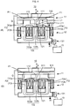
- a magnetic circuit for the winding 121 is, for example, a closed-loop circuit.
- the magnetic circuit for the winding 121 is a circuit that passes through an internal path of the winding 121, then goes out from one end portion (the end portion close to the rotor) of the internal path of the winding 121, then enters one end portion (the end portion close to the rotor) of an internal path of an adjacent winding 121, then passes through the internal path of the adjacent winding 121, then goes out from the other end portion (the end portion remote from the rotor) of the internal path of the adjacent winding 121, and then enters the other end portion (the end portion remote from the rotor) of the internal path of the winding 121.
- the internal path of the winding 121 is a path provided within the winding 121 so as to extend in the direction in which the rotor 11 and the stator 12 are opposite to each other.
- the magnetic circuit for the winding 121 partially has a non-magnetic gap such as an air gap.
- the magnetic circuit for the winding is, for example, made up of the stator core 122 and a non-magnetic gap.
- the inductance adjustment unit 131 changes an inductance L of the winding 121.
- the inductance adjustment unit 131 changes the magnetic resistance of the magnetic circuit for the winding 121, which passes through the stator core 122.
- the inductance adjustment unit 131 changes the inductance of the winding 121.
- the inductance adjustment unit 131 is an inductance adjustment mechanism.
- the inductance adjustment unit 131 is also able to adjust the current to be supplied from the generator 10 to the motor 18.
- the current adjustment device CC is arranged between the generator 10 and the motor 18.
- the current adjustment device CC is arranged in an electric power supply path between the generator 10 and the motor 18.
- the current adjustment device CC is connected to the generator 10.
- the current adjustment device CC is connected to the motor 18.
- the current adjustment device CC adjusts the current output from the generator 10 to the motor 18.
- the current adjustment device CC includes the converter 16 and the inverter 17.
- the converter 16 is connected to the generator 10.
- the inverter 17 is connected to the converter 16 and the motor 18. Electric power output from the generator 10 is supplied through the current adjustment device CC to the motor 18. In other words, electric power output from the generator 10 is supplied through the converter 16 and the inverter 17 to the motor 18.
- the current sensor 192 detects the current to be supplied from the generator 10 to the motor 18.
- the converter 16 rectifies the current output from the generator 10.
- the converter 16 converts a three-phase AC output from the generator 10 into a DC.
- the converter 16 outputs the DC.
- the converter 16 has an inverter circuit, for example.
- the converter 16 has a three-phase bridge inverter circuit, for example.
- the three-phase bridge inverter circuit includes switching elements Sa corresponding to the respective three phases.
- the operation of the converter 16 is controlled by the control device 15.
- the converter 16 changes the timing for turning on/off the switching elements Sa relative to a predetermined phase angle in the three-phase AC. In this manner, the converter 16 can adjust the current to be supplied to the motor 18. This is how the converter 16 adjusts the electric power to be supplied to the motor 18.
- the control of the converter 16 made by the control device 15 is described later.
- the inverter 17 supplies a current for driving the motor 18 to the motor 18.
- the inverter 17 is supplied with the DC from the converter 16.
- the inverter 17 converts the DC output from the converter 16 into a three-phase current with phases shifted by 120 degrees.
- the phases of the three-phase current correspond to the three phases of the three-phase brushless motor, respectively.
- the inverter 17 has a three-phase bridge inverter circuit, for example.
- the three-phase bridge inverter circuit includes switching elements Sb each corresponding to each of the three phases.
- the switching elements Sb are controlled based on a signal supplied from a position sensor (not shown) that detects the rotation position of the rotor 181.
- the inverter 17 adjusts on/off operations of the switching elements Sb, to control the voltage to be supplied to the motor 18. For example, the inverter 17 turns on the switching elements Sb based on a pulse-width-modulated signal.
- the control device 15 adjusts the duty cycle of ON/OFF. Thus, the voltage to be supplied to the motor 18 is controlled as an arbitrary value by the control device 15. This is how the inverter 17 adjusts the electric power to be supplied to the motor 18.
- the motor 18 in this embodiment is a three-phase brushless motor.
- the current adjustment device CC includes the inverter 17.
- a DC motor may be adopted as the motor 18.
- the inverter 17 is not provided.
- the current adjustment device CC includes the converter 16 alone.
- the motor 18 is operated by the electric power that is supplied from the generator 10.
- the motor 18 drives the drive wheels Wc, Wd to rotate.
- the motor 18 makes the vehicle V travel.
- the motor 18 is not mechanically connected to the generator 10.
- the motor 18 receives a current supply from the generator 10 without interposition of a battery.
- the motor 18 is, for example, a three-phase brushless motor.
- the motor 18 includes a rotor 181 and a stator 182.
- the rotor 181 and the stator 182 of the motor 18 of this embodiment have the same structure as that of the rotor 11 and the stator 12 of the generator 10.
- the rotor 181 of the motor 18 is connected to the drive wheels Wc, Wd via the transmission mechanism G.
- the generator 10 is electrically connected to the motor 18. It is therefore not necessary to arrange a mechanical power transmission between the generator 10 and the motor 18. This provides a high degree of freedom in terms of arrangement of the generator 10 and the motor 18. For example, it is possible that the generator 10 is provided in the engine 14 while the motor 18 is arranged near the drive wheels Wc, Wd serving as the driving member.
- the rotor and the stator of the motor 18 may be configured differently from those of the generator 10.
- the number of magnetic poles or the number of teeth of the motor 18 may be different from those of the generator 10.
- an induction motor or a stepper motor may be adopted as the motor 18.
- a DC motor with brushes may be adopted as the motor 18.
- the motor 18 is mechanically connected to the drive wheels Wc, Wd such that rotational power is transmitted to the drive wheels Wc, Wd.
- the motor 18 is mechanically connected to the drive wheels Wc, Wd via the transmission mechanism G. More specifically, the rotor 181 of the motor 18 is connected to the transmission mechanism G.
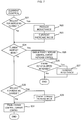
- the control device 15 controls the engine output adjustment unit 141, the inductance adjustment unit 131, and the current adjustment device CC.
- the control device 15 controls the engine output adjustment unit 141, the inductance adjustment unit 131, and the current adjustment device CC, in accordance with a current request.
- the current request is output from the request indication unit A in accordance with the amount of operation of the request indication unit A.
- the control device 15 controls the current to be supplied to the motor 18, by controlling the engine output adjustment unit 141, the inductance adjustment unit 131, and the current adjustment device CC. Since the current supplied to the motor 18 is controlled, the output torque of the motor 18 is controlled. That is, the control device 15 controls the output torque of the motor 18. Since the output torque of the motor 18 is controlled, the output torque of the drive wheels Wc, Wd serving as the driving member is controlled. That is, the control device 15 controls the output torque of the drive wheels Wc, Wd.
- the control device 15 is connected to the engine output adjustment unit 141 of the engine 14 and the inductance adjustment unit 131 of the generator 10.
- the control device 15 is also connected to the current adjustment device CC.
- the control device 15 is connected to the converter 16 and the inverter 17.
- the control device 15 is connected to the rotation angle sensor 191 and the current sensor 192.
- the control device 15 obtains information about the rotation speed of the engine 14, which means information about the rotation speed of the output shaft C of the engine 14, based on a signal supplied from the rotation angle sensor 191.
- the control device 15 obtains information about the rotation position of the rotor 181 based on a signal supplied from the rotation angle sensor 191.
- the control device 15 obtains information about the current supplied from the generator 10 to the motor 18 based on a signal supplied from the current sensor 192.
- the control device 15 includes a current request receiving unit 151, an engine control unit 152, an inductance control unit 153, and a current control unit 154.
- the current request receiving unit 151, the engine control unit 152, the inductance control unit 153, and the current control unit 154 are implemented by the central processing unit CPU of the control device 15 executing programs. An operation of each of the current request receiving unit 151, the engine control unit 152, the inductance control unit 153, and the current control unit 154, which is described later, can be considered as an operation of the control device 15.
- the engine control unit 152 controls the engine output adjustment unit 141.
- the engine control unit 152 directs the engine output adjustment unit 141 to adjust the rotational power of the engine 14.
- the current control unit 154 controls the current adjustment device CC.
- the current control unit 154 directs the current adjustment device CC to adjust the current output from the generator 10 to the motor 18.
- the current control unit 154 controls both the converter 16 and the inverter 17.
- the current control unit 154 performs a phase control on the converter 16.
- the phase control is a control for advancing or retarding/delaying a conduction timing of the switching elements Sa of the converter 16.
- each of the plurality of switching elements Sa is turned on/off with a cycle equal to the cycle of the induced voltage of the winding 121.
- Fig. 3 is a diagram showing an exemplary waveform of a voltage in the phase control.
- Vu represents the induced voltage of the stator winding W corresponding to U-phase among the stator windings W of the generator 10 corresponding to the plurality of phases.
- Vsup represents a control signal of the switching element Sa connected to the stator winding W corresponding to U-phase among the plurality of switching elements Sa included in the converter 16. More specifically, Vsup represents a control signal of two switching elements Sa connected to the stator winding W corresponding to U-phase. H level of Vsup represents ON state of the switching element Sa. L level represents OFF state. The induced voltages and the control signals of U-phase, V-phase, and W-phase are shifted by 120 degrees relative to one another.
- the current control unit 154 controls on/off of the switching element Sa connected to the stator winding W corresponding to U-phase, in accordance with the signal Vsup which has a cycle that is equal to the cycle of the induced voltage of the winding 121.
- the duty cycle of ON/OFF of the plurality of switching elements Sa is fixed.
- the current control unit 154 generates the signal Vsup which has a cycle that is equal to the cycle of the induced voltage of the winding 121 based on an output signal of the rotation angle sensor 191, for example.
- the current control unit 154 controls the current flowing from the stator winding W to the motor 18 by advancing or retarding the conduction timing of the switching element Sa in the phase control. For example, the current control unit 154 reduces the current output from the generator 10 by advancing the on/off phase of the corresponding switching element Sa relative to the induced voltage Vu. The current control unit 154 increases the current output from the generator 10 by retarding the on/off phase of the corresponding switching element Sa relative to the induced voltage Vu.
- the current control unit 154 controls the phase of on/off operation of each of the plurality of switching elements Sa relative to the phase of the induced voltage of the winding 121. As the phase of on/off operation is advanced or retarded, the current to be output from the converter 16 is increased or reduced. Thus, adjustment of the current to be output from the converter 16 is implemented by the current control unit 154 controlling the converter 16. In other words, adjustment of the current output from the generator 10 to the motor 18 is implemented by the current control unit 154 controlling the converter 16.
- the current control unit 154 performs a control different from the phase control described above.
- the current control unit 154 may perform a vector control instead of the phase control.
- the vector control is a control method in which the current of the generator 10 is divided into a d-axis component and a q-axis component, the d-axis component corresponding to the magnetic flux direction of the magnetic pole, the q-axis component being at right angles to the magnetic flux direction in the electrical angle.
- the switching element Sa is operated based on a pulse-width-modulated (PWM) signal with a cycle shorter than the cycle of the induced voltage of the winding 121.
- PWM pulse-width-modulated
- the plurality of windings 121 is rendered conductive such that a sinusoidal current flows in each phase thereof. As the duty cycle of the signal is controlled, the current to be output from the converter 16 is increased or reduced.
- the current control unit 154 directs the inverter 17 to adjust the current to be output to the motor 18.
- the current control unit 154 performs on/off operation of the plurality of switching elements Sa at timings corresponding to 120-degree conduction.
- the current control unit 154 performs a pulse-width-modulated (PWM) control on the plurality of switching elements Sa.
- PWM pulse-width-modulated
- the current control unit 154 turns on the switching element Sa based on a pulse-width-modulated signal.
- the current control unit 154 controls the duty cycle of the turn-on signal, thus adjusting the current to be output to the motor 18.
- the current control unit 154 controls the duty cycle, thus adjusting the current inputted from the converter 16 to the inverter 17.
- the current control unit 154 controls the converter 16.
- the current control unit 154 performs the pulse width modulation by using a pulse having a higher frequency than the upper limit of an audible frequency.
- the audible frequency is a frequency from 20Hz to 20kHz.
- the current control unit 154 performs a control different from the 120-degree conduction control.
- the current control unit 154 may perform a vector control, for example.
- the current control unit 154 controls the current adjustment device CC, to control the current output from the generator 10 to the motor 18.
- the load torque of the generator 10 depends on the current output from the generator 10. Therefore, the current control unit 154 controls the current adjustment device CC, to control the load torque of the generator 10.
- the inductance control unit 153 controls the inductance adjustment unit 131.
- the inductance control unit 153 directs the inductance adjustment unit 131 to adjust the inductance of the winding 121.
- the inductance control unit 153 directs the inductance adjustment unit 131 to change the magnetic resistance of the magnetic circuit for the winding 121, which passes through the stator core 122.
- the inductance control unit 153 changes the inductance of the winding 121 in this manner.
- Either the converter 16 or the inverter 17 can be used to control the current output from the generator 10. It is therefore acceptable that the current control unit 154 controls one of the converter 16 and the inverter 17 in order to control the current output from the generator 10. For example, the current control unit 154 performs the phase control on the converter 16 while performing the 120-degree conduction control on the inverter 17. In this case, the current control unit 154 makes the adjustment by advancing or retarding the phase of the converter 16, without performing the PWM control on the inverter 17. Only the converter 16 is used to control the current output from the generator 10.
- the current control unit 154 may perform the PWM control on the inverter 17, without making the adjustment by advancing or retarding the phase of the converter 16. Only the inverter 17 is used to control the current output from the generator 10.
- Fig. 4(A) and Fig. 4(B) shows schematic diagrams explaining adjustment made by the inductance adjustment unit 131 provided in the generator 10 shown in Fig. 2 .
- Fig. 4(A) shows a high-inductance state of the generator 10.
- Fig. 4(B) shows a low-inductance state of the generator 10.
- Fig. 4(A) illustrates a part of the rotor 11 and a part of the stator 12 provided in the generator 10.
- the generator 10 of this embodiment includes an SPM (Surface Permanent Magnet) generator.
- the rotor 11 and the stator 12 are opposite to each other. More specifically, the magnetic pole parts 111 of the rotor 11 and the teeth 122b of the stator core 122 of the stator 12 are opposite to each other with the air gap therebetween.
- the magnetic pole parts 111 are exposed to the stator 12.
- the inductance adjustment unit 131 changes the magnetic resistance of a magnetic circuit F2 for the winding 121, which passes through the stator core 122. In this manner, the inductance adjustment unit 131 changes the inductance of the winding 121, to adjust the current to be supplied to the motor 18. In more detail, the inductance adjustment unit 131 moves the position of the stator core 122 relative to the winding 121. This is how the inductance adjustment unit 131 changes the magnetic resistance of the magnetic circuit F2 for the winding 121, which passes through the stator core 122.
- the windings 121 are secured to a casing (not shown) of the generator 10.
- the stator core 122 is supported on the casing such that the stator core 122 is freely movable in the axial direction X relative to the windings 121.
- the windings 121 are not secured to the teeth 122b.
- a gap is ensured between each winding 121 having a cylindrical shape and each tooth 122b. The gap is to such an extent that the tooth 122b is freely movable relative to the winding 121.
- the inductance adjustment unit 131 moves the stator core 122 such that the teeth 122b are moved into and out of the cylindrically wound windings 121.
- the inductance adjustment unit 131 moves the stator core 122 in the axial direction X.
- the control device 15 operates the inductance adjustment unit 131 in accordance with the current request.
- the inductance adjustment unit 131 is schematically illustrated in the form of a rack-and-pinion mechanism and a motor.
- mechanisms other than the illustrated one may be adopted as the inductance adjustment unit 131 that moves the stator core 122.
- a mechanism including a cylindrical member that is arranged concentric with a stator core in threaded engagement with the stator core may be adopted.
- Such a mechanism is able to move the stator core in the axial direction X by, for example, rotating the cylindrical member relative to the stator core.
- the inductance adjustment unit 131 moves the position of the stator core 122 relative to the winding 121 while maintaining the position of the stator core 122 relative to the rotor 11.
- the broken lines Q indicate that the rotor 11 moves in conjunction with the stator core 122 in the axial direction X.
- a structure for maintaining the relative position between the rotor 11 and the stator core 122 is implemented by a bearing part 113 rotatably supporting the rotor 11, for example. The position of the bearing part 113 is fixed relative to the stator core 122.
- Fig. 4(A) and Fig. 4(B) illustrate primary magnetic fluxes F1 generated by the magnetic pole parts 111.
- the line of each magnetic flux F1 represents a primary magnetic circuit through which the magnetic flux F1 generated by the magnetic pole part 111 flows.
- the magnetic circuit through which the magnetic flux F1 flows is referred to as a magnetic circuit F1.
- the primary magnetic flux F1 generated by the magnetic pole part 111 flows through the magnetic pole part 111, the air gap between the magnetic pole part 111 and the tooth 122b, the tooth 122b, the core main body 122a, and the back yoke part 112.
- the magnetic circuit F1 is made up of the magnetic pole part 111, the air gap between the magnetic pole part 111 and the tooth 122b, the tooth 122b, the core main body 122a, and the back yoke part 112.
- Fig. 4(A) and Fig. 4(B) show three teeth 122b among the plurality of teeth 122b arranged in the circumferential direction.
- Fig. 4(A) and Fig. 4(B) show a state in which the magnetic pole part 111 is opposite to the middle tooth 122b among the three teeth 122b.
- the amount of magnetic flux generated by the magnetic pole part 111 and linked with the winding 121 changes.
- the change of the amount of magnetic flux linked with the winding 121 causes an induced voltage to occur in the winding 121. That is, power is generated.
- the induced voltage caused in the winding 121 depends on the amount of magnetic flux linked with the winding 121.
- the magnetic resistance of the magnetic circuit F1 depends mainly on the magnetic resistance of the air gap between the tooth 122b and the magnetic pole part 111.
- the magnetic resistance of the air gap between the tooth 122b and the magnetic pole part 111 depends on an air gap length L1 of the air gap between the tooth 122b and the magnetic pole part 111.
- the induced voltage caused in the winding 121 depends on the air gap length L1 of the air gap between the tooth 122b and the magnetic pole part 111.
- Fig. 4(A) and Fig. 4(B) illustrate a primary magnetic flux F2 generated by a current flowing in the winding 121.
- the magnetic flux F2 is generated by the current flowing in the winding 121 at the time of power generation.
- the line of each magnetic flux F2 represents a primary magnetic circuit through which the magnetic flux F2 generated by the current in the winding 121 flows.
- the magnetic circuit through which the magnetic flux F2 flows is referred to as a magnetic circuit F2.
- the magnetic circuit F2 is the magnetic circuit for the winding 121.
- the magnetic circuit F2 for the winding 121 is made up of a path passing through the inside of the winding 121 and providing the minimum magnetic resistance of the entire magnetic circuit F2.
- the magnetic circuit F2 passes through the stator core 122.
- the magnetic circuit F2 passes through adjacent teeth 122b.
- three teeth 122b among the plurality of teeth 122b arranged in the circumferential direction are shown.
- the magnetic circuit F2 for the winding 121 wound on the middle tooth 122b among the three teeth 122b is illustrated as a typical example.
- a magnetic circuit F2 for a certain winding 121 passes through a tooth 122b having the certain winding 121 wound thereon and two teeth 122b adjacent to the certain tooth 122b.
- the primary magnetic flux F2 generated by the current in the winding 121 flows through the teeth 122b, the core main body 122a, and the air gap between the two adjacent teeth 122b.
- the magnetic circuit F2 is made up of the teeth 122b, the core main body 122a, and the air gap between the two adjacent teeth 122b.
- the magnetic circuit F2 passing through the stator core 122 includes one air gap.
- a portion of the magnetic circuit F2 including the air gap is indicated by the bold line.
- the bold-line portion of the magnetic circuit F2 including the air gap is simply referred to as an air gap F2a.
- the air gap F2a exists between the winding 121 and the rotor 11.
- the air gap F2a included in the magnetic circuit F2 exists between the winding 121 and the rotor 11 and between the adjacent teeth 122b.
- the air gap F2a is a non-magnetic gap.
- a portion of the magnetic circuit F2 corresponding to the air gap F2a is provided so as to connect respective portions of the two adjacent teeth 122b opposite to the rotor 11.
- the magnetic circuit F2 for the winding 121 includes the air gap F2a between the two adjacent teeth 122b.
- the magnetic circuit F2 does substantially not include the back yoke part 112 of the rotor 11. Most of the magnetic flux F2 generated by the current in the winding 121 flows through the air gap between the two adjacent teeth 122b without going to the back yoke part 112 of the rotor 11, for the following reasons.
- the magnetic pole part 111 is considered simply as a magnetic flux path.
- the magnetic pole part 111 is made of a permanent magnet which has magnetic permeability that is as low as air.
- the magnetic pole part 111 can therefore be considered as equivalent to air for the magnetic circuit F2. Since the magnetic pole part 111 is equivalent to air, the substantial air gap length of the air gap between the stator 12 and the rotor 11 is equal to a distance L11 from the tooth 122b to the back yoke part 112.
- the distance L11 from the tooth 122b to the back yoke part 112 includes the thickness of the magnetic pole part 111 with respect to the axial direction X. Thus, the distance L11 is longer than the distance L1 from the tooth 122b to the magnetic pole part 111.
- the amount of the magnetic flux F2 generated by the current in the winding 121 is smaller than the amount of magnetic flux generated by the permanent magnet of the magnetic pole part 111. Most of the magnetic flux F2 generated by the current in the winding 121 is less likely to reach the back yoke part 112 across the air gap length L11. Little of the magnetic flux F2 generated by the current in the winding 121 flows through the back yoke part 112.
- the inductance of the winding 121 is set to the highest settable value.
- the air gap F2a included in the magnetic circuit F2 has the highest magnetic resistance among portions of the magnetic circuit F2.
- the air gap F2a has a higher magnetic resistance than that of a remaining portion F2b of the magnetic circuit F2 other than the air gap F2a.
- the inductance of the winding 121 depends on the magnetic resistance of the magnetic circuit F2 for the winding 121.
- the inductance of the winding 121 is proportionally inverse to the magnetic resistance of the magnetic circuit F2 for the winding 121.
- the magnetic resistance of the magnetic circuit F2 for the winding 121 is the magnetic resistance of the magnetic circuit F2 through which the magnetic flux F2 generated by the current in the winding 121 flows.
- the magnetic resistance of the magnetic circuit F2 for the winding 121 which passes through the stator core 122, includes the magnetic resistance of the air gap between the two adjacent teeth 122b.
- the magnetic flux F2 generated by the current in the winding 121 flows through both the stator 12 and the rotor 11. As described above, however, most of the magnetic flux generated by the current in the winding 121 flows through the air gap between the two adjacent teeth 122b without going to the back yoke part 112 of the rotor 11.
- the magnetic resistance to the winding 121 depends more strongly on the magnetic resistance of the magnetic circuit F2 passing through the stator 12 than on the magnetic resistance of the magnetic circuit F1 passing through the rotor 11. That is, the inductance of the winding 121 depends more strongly on the magnetic resistance of the magnetic circuit F2, which passes through the stator core 122 when viewed from the winding 121 side, than on the magnetic resistance of the magnetic circuit F1, which passes through the rotor 11 when viewed from the winding 121 side. Accordingly, the inductance of the winding 121 substantially depends on the magnetic resistance of the magnetic circuit F2, which passes through the stator core 122 when viewed from the winding 121 side.
- the inductance adjustment unit 131 moves the position of the stator core 122 relative to the winding 121. In this manner, the inductance adjustment unit 131 changes the magnetic resistance of the magnetic circuit F2 for the winding 121, which passes through the stator core 122. This is how the inductance adjustment unit 131 changes the inductance of the winding 121. For example, in a case of the inductance adjustment unit 131 moving the stator core 122 in a direction indicated by the arrow X1, the teeth 122b of the stator core 122 are moved out of the cylindrically wound windings 121.
- Fig. 4(B) shows a state having a lower inductance than that of the state shown in Fig. 4(A) .
- the length of the air gap F2a constituting the magnetic circuit F2 increases. This increases the magnetic resistance of the air gap F2a existing between the winding 121 and the rotor 11. That is, the magnetic resistance of the air gap F2a, which has a magnetic resistance that is highest, increases. As a result, the magnetic resistance of the magnetic circuit F2 for the winding 121, which passes through the stator core 122, increases. Consequently, the inductance of the winding 121 decreases.
- Fig. 4(B) shows a state after the inductance adjustment unit 131 moves the stator core 122 in the direction of the arrow X1.
- the movement of the stator core 122 in the direction of the arrow X1 results in an increase of the magnetic resistance of the magnetic circuit F2 for the winding 121, which passes through the stator core 122. Consequently, the inductance of the winding 121 decreases.
- the inductance adjustment unit 131 changes the magnetic resistance of the air gap F2a which has a magnetic resistance that is highest. Thus, the inductance adjustment unit 131 changes the magnetic resistance of the magnetic circuit F2 passing through the adjacent teeth 122b. This can cause a larger change of the inductance of the winding 121 as compared with, for example, changing the magnetic resistance of a portion other than the air gap F2a.
- the inductance adjustment unit 131 changes the inductance of the winding 121 such that the change rate of the inductance of the winding 121 is higher than the change rate of the magnetic flux linked with the winding 121.
- the inductance adjustment unit 131 of the generator 10 moves the position of the stator core 122 relative to the windings 121 while maintaining the position of the stator core 122 relative to the rotor 11.
- the inductance adjustment unit 131 moves the stator core 122 in the direction of the arrow X1, the rotor 11 is accordingly moved in the direction of the arrow X1. Therefore, the position of the stator core 122 relative to the rotor 11 is maintained. This can suppress a change of the air gap length L1 between the teeth 122b and the magnetic pole parts 111, which otherwise might be caused by movement of the stator core 122. Accordingly, a change of the magnetic flux F1 flowing from the magnetic pole part 111 to the stator core 122 is suppressed. That is, a change of the magnetic flux F1 linked with the winding 121 is suppressed.
- the inductance adjustment unit 131 switches the state of the generator 10 between the high-inductance state shown in Fig. 4(A) and the low-inductance state shown in Fig. 4(B) .
- the low-inductance state is a state in which the magnetic resistance of the magnetic circuit F2 for the winding 121, which passes through the stator core 122, is relatively high so that the inductance of the winding 121 is low.
- the high-inductance state is a state in which the magnetic resistance of the magnetic circuit F2 for the winding 121, which passes through the stator core 122, is relatively low so that the inductance of the winding 121 is high.
- the low-inductance state corresponds to a certain range of inductance values.
- the high-inductance state corresponds to a certain range of inductance values.
- the inductance corresponding to the low-inductance state is lower than the inductance corresponding to the high-inductance state.
- the inductance range corresponding to the low-inductance state does not overlap the inductance range corresponding to the high-inductance state.
- the inductance corresponding to the low-inductance state and the inductance corresponding to the high-inductance state are separated from each other by, for example, a boundary value.
- the boundary value is, for example, the median between the maximum and minimum inductance values obtainable under control of the inductance control unit 153.
- the inductance adjustment unit 131 changes the inductance of the winding 121 such that the change rate of the inductance of the winding 121 is higher than the change rate of the magnetic flux linked with the winding 121.
- the inductance adjustment unit 131 of the generator 10 moves the position of the stator core 122 relative to the windings 121 while maintaining the position of the stator core 122 relative to the rotor 11.
- the inductance adjustment unit 131 moves the stator core 122 in the direction of the arrow X1, the rotor 11 is accordingly moved in the direction of the arrow X1. Therefore, the position of the stator core 122 relative to the rotor 11 is maintained. This can suppress a change of the air gap length L1 between the teeth 122b and the magnetic pole parts 111, which otherwise might be caused by movement of the stator core 122. Accordingly, a change of the magnetic flux F1 flowing from the magnetic pole part 111 to the stator core 122 is suppressed. That is, a change of the magnetic flux F1 linked with the winding 121 is suppressed.
- Fig. 5(A) is a circuit diagram schematically illustrating the winding 121 of the generator 10 shown in Fig. 4(A) and Fig. 4(B) .
- a circuit corresponding to one phase is illustrated in a simplified manner, for easy understanding of the function of the winding 121.
- the winding 121 in an electrical sense includes an AC voltage source 121A, an inductor 121B, and a resistance 121C.
- the winding 121 is connected to the current adjustment device CC.
- the current adjustment device CC is under control of the current control unit 154.
- the converter 16 of the current adjustment device CC rectifies the AC generated in the winding 121.
- the inverter 17 of the current adjustment device CC generates, from the rectified DC, a three-phase pulsed current adapted to rotation of the motor.
- a current I flowing from the converter 16 to the inverter 17 is illustrated as the current supplied from the generator 10 to the motor 18.
- the current I is a DC current.
- the current supplied from the generator 10 to the motor 18 can be obtained also by detection of the current supplied from the plurality of windings 121 of the generator 10 to the converter 16.
- the current supplied from the generator 10 to the motor 18 can be obtained also by detection of the current flowing from the inverter 17 to the windings of the motor 18.
- the current adjustment device CC under control of the current control unit 154, adjusts the current I supplied from the generator 10 to the motor 18.
- the current I is controlled by one or both of the converter 16 and the inverter 17.
- the current control unit 154 controls the current I supplied from the generator 10 to the motor 18, based on a control amount.
- the control amount includes the rotation speed of the engine 14 and the current I.
- the rotation speed of the engine 14 is obtained based on a detection result made by the rotation angle sensor 191.
- the current I is obtained based on a detection result made by the current sensor 192.
- the current control unit 154 controls the current adjustment device CC in accordance with the control amount.
- the current control unit 154 controls the current I supplied from the generator 10 to the motor 18.
- the current control unit 154 Upon reception of a request for increasing the current, the current control unit 154 adjusts the current output from the generator 10 such that a shortened time is required to increase the current output from the generator 10. The current control unit 154 adjusts the current output from the generator 10 so as to minimize the time required to increase the current output from the generator 10. The current control unit 154 performs a feedback control based on the change in the amount of the rotation speed of the engine 14 and the change in the amount of the output current of the generator 10. To be specific, the current control unit 154 adjusts the current output from the generator 10 so as to increase the rotation speed of the engine 14 and increase the output current of the generator 10 (current increase mode).
- the current control unit 154 repeatedly stores a current value that is based on a detection result made by the current sensor 192, and compares the previously stored values, to obtain the change in the amount of the output current of the generator 10.
- the current control unit 154 repeatedly stores a rotation speed value that is based on a detection result made by the rotation angle sensor 191, and compares the previously stored values, to obtain the change in the amount of the rotation speed. If the rotation speed is increasing, the current control unit 154 increases the target current to be output from the generator 10.
- the current control unit 154 controls the increase in the amount of the target current to be output from the generator 10, in accordance with the increase in the amount of the rotation speed of the engine 14.
- the current control unit 154 directs the current adjustment device CC to adjust and set the current I to the target current.
- the current control unit 154 controls the current output from the generator 10 by performing the feedback control based on the change in the amount of the rotation speed of the engine 14.
- the current I varies according to the feedback control.
- the current I flows in an electrical circuit including the winding 121 of the generator 10.
- the electrical circuit through which the current I flows includes the inductor 121B.
- the current adjustment device CC changes the current I, the current I changes in accordance with response characteristics which are attributable to the inductor 121B.
- Fig. 5(B) is a graph showing exemplary response characteristics which are attributable to the inductor.
- the horizontal axis represents time.
- the vertical axis represents the current.
- the graph schematically shows an example of how the current changes over time when the circuit including the inductor is closed by the control.
- the solid line represents the change when the inductance is high.
- the broken line represents the change when the inductance is low.
- the inductance adjustment unit 131 moves the position of the stator core 122 relative to the winding 121. In this manner, the inductance adjustment unit 131 changes the magnetic resistance of the magnetic circuit F2 for the winding 121, which passes through the stator core 122. This is how the inductance adjustment unit 131 changes the inductance L of the winding 121.
- the responsiveness of the current to the current control is adjustable. Accordingly, an overshoot of the current during the current control can be suppressed.
- the inductance adjustment unit 131 changes the inductance of the winding 121 by changing the magnetic resistance of the air gap F2a existing between the winding 121 and the rotor 11.
- the magnetic pole parts 111 moving along with rotation of the rotor 11 cause an alternating magnetic field to occur between the windings 121 and the rotor 11.
- reducing the magnetic resistance of the air gap F2a existing between the winding 121 and the rotor 11 leads to a reduction of an alternating magnetic field loss.
- a core loss in the magnetic circuit F2 passing through the air gap F2a is reduced. The reduction of the loss lowers the load torque.
- a movement of the position of the stator core 122 relative to the winding 121 causes a change of the magnetic resistance of the magnetic circuit F2 for the winding 121, which passes through the stator core 122.
- the inductance L of the winding 121 is changed accordingly.
- This embodiment can gradually change the inductance L because the change of the inductance L is implemented by a change of the magnetic resistance of the magnetic circuit F2 for the winding 121, which passes through the stator core 122.
- changing the substantial number of turns of the winding is also conceivable as a method for changing the inductance.
- a terminal provided at an end of the winding and a terminal provided in the middle of the winding are selectively switched for use as a current output terminal.
- a terminal provided in the middle of the winding is short-circuited to another terminal. This changes the substantial number of turns which affect the current. As a result, the inductance is changed.
- the magnetic resistance of the magnetic circuit F2 passing through the stator core 122 is changed, so that the inductance L of the winding 121 is changed.
- the inductance L of the winding 121 can be changed gradually. This can suppress a rapid increase of the voltage occurring in the winding 121. It is therefore possible that a component having a low breakdown voltage is connected to the generator 10. This provides a high efficiency. This also eliminates the need to provide the switching element for switching the current. This also allows use of a relatively thin wire for the winding. A size increase of the generator 10 is suppressed.
- Fig. 6 is a flowchart of an operation of the vehicle V.
- the operation of the vehicle V is controlled by the control device 15 performing a control process.
- the control device 15 repeats the control process shown in Fig. 6 .
- the control is described also with reference to Fig. 2 .
- the current request receiving unit 151 of the control device 15 receives a current request (S10). To be exact, the current request receiving unit 151 receives a signal representing the current request from the request indication unit A. The current request receiving unit 151 obtains the current request based on the amount of operation of the request indication unit A. More specifically, the current request receiving unit 151 obtains the current request based on the amount of operation of the request indication unit A and the state of traveling of the vehicle V.
- control device 15 performs the current control (S20).
- the control device 15 controls the current output from the generator 10 to the motor 18, based on the current request received by the current request receiving unit 151.
- the engine control unit 152, the inductance control unit 153, and the current control unit 154 control the current.
- Fig. 7 shows a flowchart of the current control shown in Fig. 6 .
- the control device 15 determines whether a request for increasing the current is received by the current request receiving unit 151 (S21).
- the current request receiving unit 151 identifies a request for increasing the current by, for example, comparing the current request with the previous current request. If no request for increasing the current is received (S21: No), the control device 15 performs processing of step S24.
- the control device 15 reduces the inductance (S22). If a request for increasing the current is received by the current request receiving unit 151 (S21: Yes), the control device 15 reduces the inductance (S22).
- the inductance control unit 153 directs the inductance adjustment unit 131 to reduce the inductance.
- the inductance control unit 153 directs the inductance adjustment unit 131 to increase the magnetic resistance of the magnetic circuit F2 for the winding 121, which passes through the stator core 122. In this manner, the inductance control unit 153 directs the inductance adjustment unit 131 to reduce the inductance of the winding 121 to a level lower than before the request for increasing the current is received.
- the control device 15 sets the control mode of the control device 15 to a current increase mode (S23).
- the current increase mode is a mode for increasing the current to be supplied to the motor 18.
- control device 15 determines whether the control mode of the control device 15 is the current increase mode (S24).
- control mode is the current increase mode (S24: Yes)
- the control device 15 performs an engine power increase control and a current increase control (S25).
- the engine control unit 152 directs the engine output adjustment unit to increase the rotational power of the engine 14. As a result, the rotational power of the engine 14 is increased to a level higher than that of when the request for increasing the current was received.
- the current control unit 154 directs the current adjustment device CC to adjust the current output from the generator 10.
- the current control unit 154 performs the adjustment of the current output from the generator 10 such that a shortened time is required to increase the current output from the generator 10.
- the rate of increase of the current output from the generator 10 is, as mentioned above, influenced by the rate of increase of the rotation speed of the engine 14.
- the current control unit 154 directs the current adjustment device CC to adjust the current output from the generator 10 so as to increase the rotation speed of the engine 14 and increase the output current of the generator 10.
- the current control unit 154 controls the current by using the converter 16, for example.
- the current control unit 154 performs the phase control on the converter 16, for controlling the current output from the generator 10.
- the current control unit 154 performs the 120-degree conduction control on the inverter 17 without any PWM control.
- the engine control unit 152, the inductance control unit 153, and the current control unit 154 included in the control device 15 perform the following control.
- the inductance control unit 153 brings the generator 10 into the low-inductance state. That is, the inductance control unit 153 brings the generator 10 into a state in which the magnetic resistance of the magnetic circuit for the winding, which passes through the stator core, is relatively high so that the inductance of the winding is low.
- the engine control unit 152 directs the engine output adjustment unit 141 to increase the rotational power of the engine 14 to a level higher than when the request for increasing the current was received.
- the current control unit 154 adjusts the current output from the generator 10 so as to increase the rotation speed of the engine 14 and increase the output current of the generator 10.
- control device 15 determines whether the rotation speed of the engine has increased (S26). The control device 15 determines whether the rotation speed of the engine is at least higher than the rotation speed of the engine obtained when the request for increasing the current was received.
- step S26 the control device 15 determines whether the rotation speed of the engine is higher than a predetermined value, to determine whether the rotation speed has increased.
- the predetermined value is set to a value higher than the rotation speed of the engine obtained when the request for increasing the current was received.
- the predetermined value is set to such a value that the rotation speed having that value makes the load torque of the generator 10 less influential regarding the stability of rotation of the engine 14.
- the predetermined value may be a fixed value.
- the predetermined value may be a value corresponding to a predetermined percentage of the target value to which the rotation speed of the engine should be increased. It may be possible that, for example, the control device 15 determines whether the rotation speed of the engine has continuously increased over a predetermined period or longer, to determine whether the rotation speed has increased.
- the control device 15 Upon determining that the rotation speed of the engine has increased (S26: Yes), the control device 15 brings the generator 10 into the high-inductance state.
- the control device 15 increases the inductance (S27).
- the inductance control unit 153 directs the inductance adjustment unit 131 to increase the inductance.
- the inductance control unit 153 directs the inductance adjustment unit 131 to reduce the magnetic resistance of the magnetic circuit F2 for the winding 121, which passes through the stator core 122. In this manner, the inductance control unit 153 directs the inductance adjustment unit 131 to increase the inductance of the winding 121.
- control device 15 directs the inductance adjustment unit 131 to reduce the magnetic resistance of the magnetic circuit F2 for the winding 121, which passes through the stator core 122, while directing the current adjustment device CC to adjust the output current so as to increase the output current of the generator 10.
- the inductance control unit 153 directs the inductance adjustment unit 131 to increase the inductance of the winding 121 in this manner.
- the control device 15 sets the rate of increasing the inductance in the step S27 to be lower than the rate of reducing the inductance in the step S22.
- the inductance control unit 153 gradually increases the inductance over time at the step S27.
- control device 15 determines whether a request for reducing the current is received (S28).
- step S31 If no request for reducing the current is received (S28: No), the control device 15 performs the processing of step S31 which is described later. If a request for reducing the current is received (S28: Yes), the control device 15 cancels the setting of the current increase mode (S29). The control device 15 subsequently performs the processing of step S31.
- control device 15 performs an engine power control and a current control (S31).
- the engine control unit 152 directs the engine output adjustment unit to adjust the rotational power of the engine in accordance with the current request.
- the current control unit 154 directs the current adjustment device to adjust the current output from the generator in accordance with the current request.
- the engine control unit 152 reduces the rotational power of the engine.
- the current control unit 154 adjusts the current output from the generator 10.
- Fig. 8 depicts graphs each showing an example of state transition of each part of the vehicle V.
- each graph shows the state of each part in a case of accelerating the vehicle V. To be precise, each graph shows an exemplary state in a situation where the vehicle V that has been stopped with the engine 14 rotating is starting up.
- a request for increasing the current is received from the request indication unit A.
- the request indication unit A outputs the request for increasing the current.
- the request indication unit A is operated so that the request for increasing the current is received from the request indication unit A.
- the inductance control unit 153 of the control device 15 directs the inductance adjustment unit 131 to bring the generator 10 into the low-inductance state.
- the inductance adjustment unit 131 brings the generator 10 into the state in which the magnetic resistance of the magnetic circuit F2 for the winding 121, which passes through the stator core 122, is relatively high so that the inductance L of the winding 121 is low.
- the control device 15 performs a control such that the low-inductance state of the generator 10 is maintained after the time t1.
- the control device 15 brings the generator 10 into the low-inductance state, and additionally directs the engine output adjustment unit to increase the rotational power of the engine 14. After the time t1, an output torque Te of the engine 14 increases as the rotational power increases. The output torque Te of the engine gradually increases over time.
- the control device 15 brings the generator 10 into the low-inductance state, and additionally directs the current adjustment device CC to adjust the output current of the generator 10.
- a change of the output current of the generator 10 is similar to a change of a load torque Tg of the generator 10 shown in the graph of Fig. 8 .
- the change of the load torque Tg of the generator represents the change of the output current of the generator 10.
- the control device 15 directs the current adjustment device CC to adjust the output current of the generator 10 so as to increase a rotation speed Ve of the engine 14 and increase the output current of the generator 10.
- An increase of the rotation speed Ve of the engine 14 occurs on condition that the load torque Tg of the generator 10 is lower than the output torque Te of the engine 14.
- the control device 15, therefore, adjusts the output current of the generator 10 such that the load torque Tg of the generator 10 falls below the output torque Te of the engine 14.
- the control device 15 nevertheless increases the output current of the generator 10 over time.
- the output current of the generator 10 is, in the graph of Fig. 8 , represented by a waveform of the load torque Tg of the generator 10.
- the control device 15 sets a control target of the output current of the generator 10 based on the change of the rotation speed Ve of the engine 14 and the change of the output current of the generator 10 (see the waveform of the load torque Tg).
- the control device 15 controls the current adjustment device CC such that the output current of the generator 10 reaches the set control target.
- the broken line indicating the load torque Tg of the generator represents an ideal change of the load torque in which the output current of the generator 10 increases in accordance with the control target.
- the output current of the generator 10 is changed by the control, an actual output current deviates from the target due to the transient characteristics of the circuit.
- the output current has an overshoot.
- the output current deviates in a vibrating form.
- the actual load torque Tg of the generator 10 deviates, like vibrating up and down, from the ideal load torque represented by the broken line in Fig. 8 .
- An increase of the rotation speed Ve of the engine 14 is suppressed if, for example, the load torque Tg of the generator 10 approaches the output torque Te of the engine 14 or exceeds the output torque Te of the engine 14 as a result of the deviation of the output current from the control target.
- a required time to increase the rotation speed Ve of the engine 14 is prolonged. Consequently, a required time to increase the output current of the generator 10 is prolonged. That is, acceleration performance of the vehicle decreases.
- the rotation of the engine 14 becomes unstable.
- This embodiment brings the generator 10 into the low-inductance state upon reception of a request for increasing the current. This achieves a fast response of the current to the current control. As a result, deviation of the output current due to the transient characteristics is suppressed.
- the load torque Tg of the generator 10 is likely to increase in accordance with the target represented by the broken line.
- the rotation of the engine 14 is stabilized.
- occurrence of a situation is suppressed in which the load torque Tg of the generator 10 approaches the output torque Te of the engine 14 or exceeds the output torque Te of the engine 14. Accordingly, a required time to increase the output current of the generator 10 is shortened. This achieves improvement of the acceleration performance.
- the current flowing from the generator to the motor is adjusted by on/off operation of the switching elements Sa, as described with reference to Fig. 3 .
- the current flowing in the winding 121 has transient characteristics with respect to on/off operation of the switching elements Sa, too.
- the current flowing in the winding 121 has a delay with respect to on/off operation of the switching elements Sa.
- the current flowing in the switching element Sa gradually increases.
- the switching element Sa is turned off, the current flowing in the switching element Sa gradually decreases.
- a current component that flows in the switching element Sa with a delay causes a loss.
- power efficiency decreases.
- the loss caused by the delay is larger particularly when the PWM control is performed on the switching element Sa than when the PWM control is not performed thereon.
- Lowering the frequency of on/off operation leads to a reduction of the loss caused by the delay.
- Lowering the frequency leads to an increase of audible noise.
- the generator 10 upon reception of a request for increasing the current, the generator 10 is adjusted into the state having a lower inductance. Since the inductance is low, the transient characteristics which are attributable to the inductance of the winding 121 are improved. Accordingly, a loss caused by a current component that flows in the switching element Sa with a delay can be suppressed. This enables the current to be supplied from the generator 10 to the motor with a high efficiency in response to the request for increasing the current.
- the control device 15 directs the inductance adjustment unit 131 to bring the generator 10 into the high-inductance state.
- the inductance adjustment unit 131 brings the generator 10 into the state in which the magnetic resistance of the magnetic circuit F2 for the winding 121, which passes through the stator core 122, is relatively low so that the inductance of the winding 121 is high.
- the rotation speed Ve of the engine 14 is higher than the rotation speed Ve obtained when the request for increasing the current is received.
- the output torque Te of the engine 14 is higher than the output torque Te obtained when the request for increasing the current is received. Therefore, a change of the rotation speed of the engine 14 can be suppressed even if the load torque of the generator is changed by a high inductance Le. Accordingly, the current supplied from the generator 10 to the motor 18 can be increased by the high rotation speed with stabilized rotation of the engine 14.
- the control device 15 sets the rate of increasing the inductance to be lower than the rate at which the inductance is reduced at the time t1.
- the control device 15 sets the rate of reducing the magnetic resistance of the magnetic circuit F2 for the winding 121, which passes through the stator core 122, to be lower than the rate at which the magnetic resistance is increased at the time t1.
- the control device 15 gradually reduces over time the magnetic resistance of the magnetic circuit F2 for the winding 121, which passes through the stator core 122. In this manner, the control device 15 gradually increases the inductance.
- the induced voltage of the winding 121 is likely to increase. That is, the current output from the generator 10 is likely to increase.
- the load torque of the generator 10 is likely to increase.
- a rapid increase of the induced voltage can be suppressed because the magnetic resistance is gradually reduced while the rotation speed Ve is higher than the rotation speed Ve obtained at the time (t1) when the request for increasing the current was received.
- a situation in which the rotation of the engine 14 becomes unstable can be suppressed.
- the control device 15 Upon reception of a request for reducing the current at time t3, the control device 15 suppresses the increase of the rotational power of the engine 14. The increase of the output torque Te of the engine 14 is suppressed accordingly. Moreover, the output current of the generator 10 is controlled such that the rotation speed Ve of the engine is maintained. That is, the output current of the generator 10 is controlled such that the load torque Tg of the generator 10 can be balanced with the output torque Te of the engine 14.
- the control device 15 reduces the rotational power of the engine 14 (t4).
- the output torque Te of the engine 14 decreases accordingly.
- the rotation speed Ve of the engine 14 decreases.
- Each graph of Fig. 8 shows an exemplary state of each part in a situation where the vehicle V that has been stopped is starting up.
- the above-described operations are also applicable to a situation where the traveling vehicle V accelerates. If the control device 15 receives a request for increasing the current while traveling, the control device 15 reduces the inductance.
- Fig. 9(A) and Fig. 9(B) show schematic diagrams explaining adjustment made by an inductance adjustment unit provided in a generator 20 according to the second embodiment.
- Fig. 9(A) shows a state in which the inductance of the winding 121 is set to the highest settable value.
- Fig. 9(B) shows a state in which the inductance of the winding 121 is set to a value lower than that of Fig. 9(A) .
- Fig. 9(A) The positional relationship among windings 221, a stator core 222, and a rotor 21 shown in Fig. 9(A) is the same as the positional relationship thereamong in the first embodiment having been described with reference to Fig. 4(A) .
- a magnetic circuit F21 is a magnetic circuit through which a magnetic flux generated by a magnetic pole part 211 flows.
- a magnetic circuit F22 is a magnetic circuit for the winding 221.
- the magnetic circuit F22 for the winding 221 is made up of a path passing through the inside of the winding 221 and providing the minimum magnetic resistance of the entire magnetic circuit F22.
- the magnetic circuit F22 passes through the stator core 222.
- the magnetic circuit F22 passes through two adjacent teeth 222b.
- the magnetic circuit F22 passing through the stator core 222 includes an air gap F22a.
- the air gap F22a exists between the winding 221 and the rotor 21.
- the air gap F22a included in the magnetic circuit F22 exists between the winding 221 and the rotor 21 and between the two adjacent teeth 222b.
- the air gap F22a is a non-magnetic gap.
- the air gap F22a included in the magnetic circuit F22 is provided so as to connect respective portions of the two adjacent teeth 222b opposite to the rotor 21.
- the magnetic circuit F22 for the winding 121 which does not pass through a back yoke part 212 of the rotor 21, includes the air gap F22a between the two adjacent teeth 122b.
- the air gap F22a included in the magnetic circuit F22 has the highest magnetic resistance among portions of the magnetic circuit F22.
- the air gap F22a has a higher magnetic resistance than that of a remaining portion F22b of the magnetic circuit F22 other than the air gap F22a.
- an inductance adjustment unit 231 moves the winding 221 in accordance with a requested current.
- the inductance adjustment unit 231 changes the magnetic resistance of the magnetic circuit F22 for the winding 221, which passes through the stator core 222.
- the inductance adjustment unit 231 changes the inductance of the winding 221, to adjust the current to be supplied to the motor 18 (see Fig. 1 ).
- the inductance adjustment unit 231 moves the windings 221 without moving the stator core 222 of the stator 22.
- stator core 222 is secured to a casing (not shown).
- the rotor 21 is rotatably supported on the casing.
- the rotor 21 is secured or fixed with respect to the axial direction X.
- the windings 221 are supported on the casing such that the windings 221 are freely movable in the axial direction X relative to the casing.
- the inductance adjustment unit 231 moves the windings 221 in such a direction that the teeth 222b come into and out of the cylindrical shapes of the windings 221.
- the inductance adjustment unit 231 moves the windings 221 in the axial direction X.
- the inductance adjustment unit 231 moves the windings 221 in a direction indicated by the arrow X2, for example.
- the control device 15 operates the inductance adjustment unit 231 in accordance with the current request.
- Fig. 9(B) shows a state having a lower inductance than that of the state shown in Fig. 9(A) .
- the state shown in Fig. 9(B) is a state after the windings 221 are moved in the direction of the arrow X2.
- the inductance adjustment unit 231 moves the windings 221 alone. All of the plurality of windings 221 wound on the plurality of teeth 222b are moved integrally. In this manner, the inductance adjustment unit 231 moves the position of the stator core 222 relative to the windings 221. Thus, the inductance adjustment unit 231 changes the magnetic resistance of the magnetic circuit F22 for the winding 221, which passes through the stator core 222.
- the teeth 222b of the stator core 222 are pulled out of the windings 221.
- Pulling the teeth 222b out of the windings 221 reduces the volume of the stator core 222 existing within the windings 221.
- the length of the air gap F22a included in the magnetic circuit F22 for the winding 221 increases.
- the magnetic resistance of the magnetic circuit F22 for the winding 221 increases. Consequently, the inductance of the winding 221 decreases.
- the inductance adjustment unit 231 changes the magnetic resistance of the air gap F22a which has a magnetic resistance that is highest. Thus, the inductance adjustment unit 231 changes the magnetic resistance of the magnetic circuit F22 passing through the adjacent teeth 222b. This can easily cause a larger change of the inductance of the winding 221 as compared with, for example, changing the magnetic resistance of the portion F22b other than the air gap F22a.
- the inductance adjustment unit 231 changes the magnetic resistance of the magnetic circuit F22 for the winding 221.
- the inductance adjustment unit 231 changes the inductance of the winding 221.
- the inductance adjustment unit 231 increases the magnetic resistance of the magnetic circuit F22 passing through the stator core 222 when viewed from the winding 221 side, in accordance with a request for increasing the current.
- the inductance adjustment unit 231 reduces the inductance of the winding 221.
- the inductance adjustment unit 231 changes the inductance of the winding 221 by changing the magnetic resistance of the air gap F22a existing between the winding 221 and the rotor 21. This results in a reduction of an alternating magnetic field loss. Accordingly, the current to be supplied to the motor 18 serving as the electrical load device can be adjusted to an increased degree.
- Fig. 10 is a schematic diagram showing a generator 30 of a drive system according to the third embodiment.
- a stator core 322 provided in the generator 30 shown in Fig. 10 includes a plurality of first stator core parts 323 and a second stator core part 324.
- Each of the plurality of first stator core parts 323 is provided with a facing portion 323a that is opposite to the rotor 31 with an air gap there between.
- the plurality of first stator core parts 323 is annularly arranged at intervals. That is, the plurality of first stator core parts 323 aligns in the circumferential direction Z.
- the plurality of first stator core parts 323 functions as primary teeth in the stator 32.
- the first stator core parts 323 may also be referred to as first teeth 323.
- the length of the facing portion 323a of the first stator core part 323 with respect to the circumferential direction Z is longer than the length of any portion of the first stator core part 323 other than the facing portion 323a with respect to the circumferential direction Z.
- a winding 321 is wound on each of the first stator core parts 323.
- the second stator core part 324 is arranged at a position opposite to the rotor 31 across the first stator core parts 323.
- the first stator core parts 323 are arranged between the second stator core part 324 and the rotor 31.
- the second stator core part 324 is not provided with the facing portion 323a that is opposite to the rotor 31.
- the second stator core part 324 includes a stator yoke portion 324a having an annular shape and a plurality of second teeth 324b.
- the second teeth 324b protrude from the stator yoke portion 324a toward the first stator core part 323.
- the number of the second teeth 324b is equal to the number of the first stator core parts 323.
- the stator yoke portion 324a and the second teeth 324b may be configured such that substantially all of the magnetic fluxes flowing through the second teeth 324b flow through the stator yoke portion 324a. That is, the second teeth 324b may be formed integral with the stator yoke portion 324a. Alternatively, the second teeth 324b may be formed separate from the stator yoke portion 324a such that they are attachable to the stator yoke portion 324a. The second teeth 324b are arranged so as to align in the circumferential direction Z. The plurality of second teeth 324b is annularly arranged at intervals equal to the intervals of the first stator core parts 323.
- a inductance adjustment unit 331 of the generator 30 of this embodiment moves the position of a part of the stator core 322 relative to the winding 321.
- the inductance adjustment unit 331 moves one of the plurality of first stator core parts 323 and the second stator core part 324 relative to the other.
- the inductance adjustment unit 331 changes the magnetic resistance for the winding 321. This is how the inductance adjustment unit 331 adjusts the inductance.
- the inductance adjustment unit 331 is controlled by the control device 15.
- the first stator core parts 323 are secured to a casing (not shown).
- the second stator core part 324 is supported so as to be rotatable in the circumferential direction Z.
- the inductance adjustment unit 331 rotates the second stator core part 324 in the circumferential direction Z about the rotation axis of the rotor 31. In this manner, the inductance adjustment unit 331 moves the second stator core part 324 from a first state (see Fig. 11(A) ) to a second state (see Fig. 11(B) ).
- Fig. 11(A) shows a schematic diagram of the first state of the stator 32 shown in Fig. 10 .
- Fig. 11(B) shows a schematic diagram of the second state of the stator 32 shown in Fig. 10 .
- the first state shown in Fig. 11(A) is the high-inductance state.
- the inductance of the winding 321 is set to the highest settable value.
- the inductance of the winding 321 is set to a value lower than that of Fig. 11(A) .
- each of the plurality of second teeth 324b is positioned with respect to the circumferential direction Z so as to confront or face each of the plurality of first stator core parts 323.
- an air gap length L32 between each of the plurality of first stator core parts 323 and the second stator core part 324 is shorter than an air gap length L33 between adjacent ones of the plurality of first stator core parts 323.
- the air gap length L33 is the length of an air gap formed between respective portions of the first stator core parts 323, each of the portions arranged between the winding 321 and the rotor 31 with respect to a direction in which the rotor 31 and the stator 32 are opposite to each other.
- the second state shown in Fig. 11(B) is the low-inductance state.
- each of the plurality of second teeth 324b is positioned between adjacent ones of the first stator core parts 323 with respect to the circumferential direction Z.
- an air gap length L34 between each of the plurality of first stator core parts 323 and the second stator core part 324 is longer than the air gap length L33 between adjacent ones of the plurality of first stator core parts 323.
- Fig. 11(A) and Fig. 11(B) illustrate a magnetic circuit F31 through which a magnetic flux generated by a magnetic pole part 311 flows, and a magnetic circuit F32 for the winding 321.
- the magnetic circuit F32 for the winding 321 is made up of a path passing through the inside of the winding 321 and providing the minimum magnetic resistance of the entire magnetic circuit F32.
- the magnetic circuit F32 passes through the stator core 322.
- the magnetic circuit F32 passes through adjacent first stator core parts 323 (first teeth 323).
- the magnetic circuit F32 includes three air gaps. A portion of the magnetic circuit F32 corresponding to an air gap between the two adjacent first stator core parts 323 (first teeth 323) is referred to as an air gap F32a. Portions of the magnetic circuit F32 corresponding to air gaps each between each of the two adjacent first stator core parts 323 (first teeth 323) and the second stator core part 324 are referred to as air gaps F32c.
- the air gap F32a between the two adjacent first stator core parts 323 (first teeth 323) exists between the winding 321 and the rotor 31.
- the air gap F32a included in the magnetic circuit F32 exists between the winding 321 and the rotor 31 and between the two adjacent first stator core parts 323 (first teeth 323).
- the air gap F32a is provided so as to connect mutually opposite end surfaces of the respective two adjacent first stator core parts 323 (first teeth 323).
- the air gap length L32 between each of the plurality of first stator core parts 323 (first teeth 323) and the second stator core part 324 is shorter than the air gap length L33 between adjacent ones of the plurality of first stator core parts 323 (first teeth 323).
- the air gap length L33 is the largest air gap length in the magnetic circuit F32.
- the air gap F32a between the adjacent first stator core parts 323 has the highest magnetic resistance among portions of the magnetic circuit F32 for the winding 321.
- the magnetic resistance of the air gap F32a is higher than the magnetic resistance of any of remaining portions F32b, F32c, and F32d of the magnetic circuit F32 other than the air gap F32a.
- the magnetic resistance of the air gap F32a is higher than the magnetic resistance of the air gap F32c between the first stator core part 323 and the second stator core part 324.
- the magnetic flux F32 generated by the current in the winding 321 flows through the adjacent first stator core parts 323 and the second stator core part 324, as shown in Fig. 11(A) .
- the magnetic resistance of the magnetic circuit F32 for the winding 321, which passes through the stator core 322, depends on the air gap length L33 between the adjacent first stator core parts 323.
- the magnetic flux F31 generated by the magnetic pole part 311 flows through the two adjacent first stator core parts 323.
- the magnetic flux F31 flows through one magnetic pole part 311, a gap between the magnetic pole part 311 and the first stator core part 323, the first stator core part 323, the second stator core part 324, an adjacent first stator core part 323, a gap between the first stator core part 323 and the magnetic pole part 311, an adjacent magnetic pole part 311, and the back yoke part 312.
- the magnetic flux F31 of the magnetic pole part 311 flows in the two adjacent first stator core parts 323 and the second stator core part 324.
- the air gap length L34 between each of the plurality of first stator core parts 323 and the second stator core part 324 is longer than the air gap length L33 between adjacent ones of the plurality of first stator core parts 323. Therefore, the magnetic resistance of the magnetic circuit F32 for the winding 321, which passes through the stator core 322, is strongly influenced by the air gap length L34 between the first stator core part 323 and the second stator core part 324. As a result, in the second state, the magnetic resistance of the magnetic circuit F32 for the winding 321, which passes through the stator core 322, is higher than the magnetic resistance in the first state.
- the magnetic flux F31 generated by the magnetic pole part 311 flows through one magnetic pole part 311, the gap between the magnetic pole part 311 and the first stator core part 323, and the first stator core part 323.
- the magnetic flux F31 flows from the first stator core part 323 directly to the adjacent first stator core part 323.
- the magnetic flux F31 generated by the magnetic pole part 311 flows through a gap between the two adjacent first stator core parts 323. In the second state, the path of the magnetic flux F31 generated by the magnetic pole part 311 is switched in the above-described manner.
- the magnetic resistance of the magnetic circuit F32 including the air gap F32a is further increased.
- the change rate of the inductance of the winding 321 is higher than the change rate of the magnetic flux that is generated by the magnetic pole part 311 and is linked with the winding 321.
- the inductance of the winding 321 is liable to be proportionally inverse to the magnetic resistance for the winding 321. Therefore, the inductance of the winding 321 in the second state is lower than the inductance of the winding 321 in the first state.
- the inductance adjustment unit 331 moves one of the plurality of first stator core parts 323 and the second stator core part 324 relative to the other so as to shift from the first state (see Fig. 11(A) ) to the second state (see Fig. 11(B) ). In this manner, the inductance adjustment unit 331 changes the magnetic resistance for the winding 321. Thus, the inductance adjustment unit 331 changes the inductance of the winding 321.
- the inductance adjustment unit 331 changes the magnetic resistance of the air gap F32a.
- the inductance adjustment unit 331 changes the magnetic resistance of the air gap F32a without changing the air gap length L33 between the first stator core parts 323 serving as the adjacent teeth.
- the inductance adjustment unit 331 changes the magnetic resistance of the magnetic circuit F32 passing through the first stator core parts 323 serving as the adjacent teeth.
- the air gap F32a has the highest magnetic resistance among portions of the magnetic circuit F32. This can provide a larger change of the inductance of the winding 321 than, for example, changing the magnetic resistance of portions other than the air gap F32a.
- the inductance adjustment unit 331 changes the inductance of the winding 321 by changing the magnetic resistance of the air gap F32a existing between the winding 321 and the rotor 31. This results in a reduction of an alternating magnetic field loss. Accordingly, the current to be supplied to the motor 18 serving as the electrical load device can be adjusted to an increased degree.
- a supply voltage adjustment unit 344 of the generator 30 is described.
- the generator 30 includes the supply voltage adjustment unit 344 in addition to the inductance adjustment unit 331.
- the supply voltage adjustment unit 344 is under the control of the control device 15.
- the supply voltage adjustment unit 344 changes a linkage flux flowing from the magnetic pole part 311 of the rotor 31 and linked with the winding 321. In this manner, the supply voltage adjustment unit 344 changes the induced voltage E of the winding 321. This is how the supply voltage adjustment unit 344 adjusts the voltage to be supplied to the motor 18. To be specific, the supply voltage adjustment unit 344 moves the rotor 31 in the axial direction X. Thus, the supply voltage adjustment unit 344 changes an air gap length L31 between the rotor 31 and the stator 32.
- Such a movement of the rotor 31 in the axial direction X is implemented by, for example, the supply voltage adjustment unit 344 configured to move a bearing part 313 in the axial direction X, the bearing part 313 supporting the rotor 31 in a rotatable manner.
- the change of the air gap length L31 between the rotor 31 and the stator 32 leads to a change of the magnetic resistance between the rotor 31 and the stator 32.
- the amount of the magnetic flux generated by the magnetic pole part 311 and linked with the winding 321 is changed.
- the voltage generated by the generator 30 is changed accordingly.
- the generator 30 includes both the inductance adjustment unit 331 and the supply voltage adjustment unit 344.
- the supply voltage adjustment unit is not indispensable in the drive system of the present invention.
- the converter has a bridge circuit including diodes. That is, the converter may be configured as a rectifier. In such a case, the converter may include a regulator circuit capable of controlling the output current. The regulator circuit adjusts the current rectified by the rectifier, in accordance with a control performed by the control device. That is, the converter may be a rectifier regulator.
- the converter may include a rectifier without including a regulator circuit. With such a configuration, the converter performs rectification alone, and does not control the current.
- the engine output adjustment unit of the present invention uses both the throttle valve adjustment mechanism and the fuel injection device, to adjust the rotational power.
- the engine output adjustment unit may adjust the rotational power by using either the throttle valve adjustment mechanism or the fuel injection device.
- the engine output adjustment unit in the present invention may be, for example, a valve arrangement that adjusts the flow rate of a gaseous fuel.
- the engine in the present invention may use a liquid fuel or a gaseous fuel.
- the vehicle V having four wheels is illustrated as an example. Applications of the present invention, however, are not limited thereto, and it may be applicable to a vehicle with three or fewer wheels, a vehicle with five or more wheels, and a vehicle with no wheel.
- the present invention is applicable to, for example, a vehicle provided with wheels.
- the present invention is applicable to, for example, motorcycles, motor tricycles, buses, trucks, golf carts, carts, ATVs (All-Terrain Vehicles), ROVs (Recreational Off-highway Vehicles), and track-type vehicles.
- the wheel is not the only example of the driving member.
- the driving member may be, for example, a propeller, an impeller, a caterpillar, or a track belt.
- the present invention is applicable to, for example, industrial vehicles typified by forklifts, snow blowers, agricultural vehicles, military vehicles, snowmobiles, construction machines, small planing boats (water vehicles), marine crafts, outboard engines, inboard engines, airplanes, and helicopters.
- industrial vehicles typified by forklifts, snow blowers, agricultural vehicles, military vehicles, snowmobiles, construction machines, small planing boats (water vehicles), marine crafts, outboard engines, inboard engines, airplanes, and helicopters.
- the rotor and the stator having an axial gap structure are illustrated as an example.
- the present invention is also applicable to a radial gap structure in which a rotor and a stator are opposite to each other with an air gap there between with respect to a radial direction.
- the axial direction X ( Fig. 4 ) defined in the axial gap structure of these embodiments is one example of the direction in which the rotor and the stator of the present invention are opposite to each other.
- the rotor and the stator are opposite to each other with respect to the radial direction.
- the generator including an SPM generator is illustrated as an example.
- the generator of the present invention may be an IPM (Interior Permanent Magnet) generator.
- the air gap illustrated in the embodiments described above is one example of the non-magnetic gap.
- the non-magnetic gap is a gap made of a single type of a non-magnetic material or a plurality of types of non-magnetic materials. No particular limitation is put on the non-magnetic material. Examples of the non-magnetic material include air, aluminum, and resins. It is preferable that the non-magnetic gap includes at least an air gap.
- the configuration in which the rotor 11 is connected directly to the output shaft C of the engine 14 is illustrated as a specific example of the configuration in which the rotor 11 is connected to the engine 14.
- the output shaft C of the engine 14 and the rotor 11 of the generator 10 may be connected with interposition of a transmission mechanism as typified by a belt, a gear, or a drive shaft.
- the accelerator operator is illustrated as an example of the request indication unit A.
- the current request of the present invention is not limited to the output of the accelerator operator.
- the following are some examples of the request indication unit and the current request required by the request indication unit:
- the three-phase brushless motor is illustrated as an example of the motor.
- the motor of the present invention may be a motor having the same structure as that of the generator illustrated in the embodiments, including the structure of the inductance adjustment unit.
- the motor may be structured so as to include the plurality of first stator core parts and the second stator core part and configured to move one of the first stator core parts and the second stator core part relative to the other.
- the vehicle of the present invention may be provided with a battery that stores electric power generated by the generator.
- the generator may be operated by the electric power stored in the battery, to function as a starter of the engine.
- the motor of the vehicle may be operated by the electric power stored in the battery.
- both the generator and the battery may concurrently supply electric power to the motor, for operating the motor. It is nevertheless preferable to supply electric power from the generator to the motor, without providing any battery that supplies electric power for driving the motor.
- Such a configuration eliminates constraints on the engine rotation and the need of any control for protecting the battery, which otherwise might be necessary due to constraints on the battery voltage.
- control device 15 constituted of a microcontroller is illustrated as an example of the control device. This, however, does not limit the present invention.
- the control device may be constituted of a wired logic, for example.
- All or part of the current request receiving unit, the engine control unit, the inductance control unit, and the current control unit may be provided as separate devices.
- the change of the inductance of the winding is implemented by changing the magnetic resistance of the magnetic circuit for the winding, which passes through the stator core.
- the change of the magnetic resistance of the magnetic circuit for the winding, which passes through the stator core may be implemented in a plurality of stages or in a single stage, or may be implemented continuously.
- the output current characteristics of the generator may be changed in a plurality of stages or in a single stage, or may be changed continuously.
- the magnetic resistance of the magnetic circuit for the winding, which passes through the stator core may be changed in two stages.
- the control device is configured to determine an output of the control device in accordance with an input to the control device.
- the control device is able to control both the engine output adjustment unit and the inductance adjustment unit by the central processing unit executing the program to perform the above-described operations.
- the program includes a map or table used for determining an output of the control device in accordance with an input to the control device. In the map, data about the input to the control device and data about the output of the control device are associated with each other. In such a configuration, the program causes the computer to refer to the map when the computer determines an output of the control device in accordance with an input to the control device.
- control device adjusts the generator into the state in which the magnetic resistance of the magnetic circuit for the winding, which passes through the stator core, is relatively high so that the inductance is low, every time a request for increasing the current is received.
- the state may be maintained in which the magnetic resistance of the magnetic circuit for the winding, which passes through the stator core, is relatively low.
- the low-inductance state is a state in which the inductance of the winding is adjusted by the inductance control unit to a value smaller than the boundary value (e.g., the median) between the maximum and minimum inductance values obtainable under the control of the inductance control unit 153.
- the high-inductance state is a state in which the inductance of the winding is adjusted by the inductance control unit to a value greater than the boundary value.
- the magnetic resistance of the magnetic circuit for the winding, which passes through the stator core, in the low-inductance state is higher than the magnetic resistance of the magnetic circuit for the winding, which passes through the stator core, in the high-inductance state.
- the low-inductance state may be a state in which the inductance of the winding is adjusted by the inductance control unit to a value smaller than the value of the inductance of the winding obtained at a time when a request for increasing the current was received.
- the high-inductance state may be a state in which the inductance of the winding is adjusted by the inductance control unit to a value greater than the value of the inductance of the winding obtained at the time when the request for increasing the current was received.
- the boundary value may be the value of the inductance of the winding at the time when the request for increasing the current was received.
- control device performs such a control that the inductance adjustment unit adjusts the generator into the low-inductance state upon reception of a request for increasing the current, and then adjusts the generator into the high-inductance state if the rotation speed of the engine is higher than the rotation speed of the engine obtained when the request for increasing the current was received.
- the inductance adjustment unit adjusts the generator into the low-inductance state, and then if the rotation speed of the engine is higher than the rotation speed of the engine obtained when the request for increasing the current was received, adjusts the inductance of the winding of the generator such that the inductance value rises from the minimum inductance value of the winding obtainable in the low-inductance state.
- the adjustment of the inductance of the winding may be performed until the generator reaches the high-inductance state.
- the adjustment of the inductance of the winding may be performed when the generator is in the low-inductance state.
Landscapes
- Engineering & Computer Science (AREA)
- Power Engineering (AREA)
- Transportation (AREA)
- Mechanical Engineering (AREA)
- Chemical & Material Sciences (AREA)
- Combustion & Propulsion (AREA)
- Physics & Mathematics (AREA)
- General Physics & Mathematics (AREA)
- Automation & Control Theory (AREA)
- Life Sciences & Earth Sciences (AREA)
- Sustainable Development (AREA)
- Sustainable Energy (AREA)
- Health & Medical Sciences (AREA)
- Biomedical Technology (AREA)
- General Health & Medical Sciences (AREA)
- Electric Propulsion And Braking For Vehicles (AREA)
- Control Of Eletrric Generators (AREA)
- Hybrid Electric Vehicles (AREA)
- Control Of Vehicle Engines Or Engines For Specific Uses (AREA)
- Control Of Ac Motors In General (AREA)
- Combined Controls Of Internal Combustion Engines (AREA)
- Permanent Magnet Type Synchronous Machine (AREA)
- Arrangement Or Mounting Of Propulsion Units For Vehicles (AREA)
Applications Claiming Priority (6)
| Application Number | Priority Date | Filing Date | Title |
|---|---|---|---|
| JP2014237372A JP2018014771A (ja) | 2014-11-25 | 2014-11-25 | 電流供給システム及び電力供給システム |
| JP2015196670A JP2018012349A (ja) | 2015-10-02 | 2015-10-02 | 電力供給システム、制御装置、ビークル、及びビークル駆動用エンジン発電機ユニット |
| JP2015196667A JP2018012346A (ja) | 2015-10-02 | 2015-10-02 | ビークル、及びビークル駆動用エンジン発電ユニット |
| JP2015196668A JP2018012347A (ja) | 2015-10-02 | 2015-10-02 | 駆動システム、制御装置、及びビークル |
| JP2015196669A JP2018012348A (ja) | 2015-10-02 | 2015-10-02 | 変速装置、制御装置、及びビークル |
| PCT/JP2015/082933 WO2016084803A1 (ja) | 2014-11-25 | 2015-11-24 | ビークル |
Publications (3)
| Publication Number | Publication Date |
|---|---|
| EP3206294A1 true EP3206294A1 (de) | 2017-08-16 |
| EP3206294A4 EP3206294A4 (de) | 2017-11-08 |
| EP3206294B1 EP3206294B1 (de) | 2019-10-30 |
Family
ID=56074358
Family Applications (6)
| Application Number | Title | Priority Date | Filing Date |
|---|---|---|---|
| EP15864204.1A Active EP3206296B1 (de) | 2014-11-25 | 2015-11-24 | Stromversorgungssystem, steuerungsvorrichtung, fahrzeug sowie motor- generatoreinheit für fahrzeugantrieb |
| EP15862664.8A Active EP3206294B1 (de) | 2014-11-25 | 2015-11-24 | Fahrzeug |
| EP15863113.5A Active EP3206295B1 (de) | 2014-11-25 | 2015-11-24 | Übertragungsvorrichtung, steuerungsvorrichtung und fahrzeug |
| EP15862530.1A Active EP3206293B1 (de) | 2014-11-25 | 2015-11-24 | Antriebssystem und fahrzeug |
| EP15862418.9A Active EP3206292B8 (de) | 2014-11-25 | 2015-11-24 | Elektrisches stromversorgungssystem, elektrisches leistungsversorgungssystem und steuerungsvorrichtung |
| EP15862961.8A Active EP3205524B1 (de) | 2014-11-25 | 2015-11-24 | Fahrzeug und motor-generatoreinheit für den antrieb eines fahrzeugs |
Family Applications Before (1)
| Application Number | Title | Priority Date | Filing Date |
|---|---|---|---|
| EP15864204.1A Active EP3206296B1 (de) | 2014-11-25 | 2015-11-24 | Stromversorgungssystem, steuerungsvorrichtung, fahrzeug sowie motor- generatoreinheit für fahrzeugantrieb |
Family Applications After (4)
| Application Number | Title | Priority Date | Filing Date |
|---|---|---|---|
| EP15863113.5A Active EP3206295B1 (de) | 2014-11-25 | 2015-11-24 | Übertragungsvorrichtung, steuerungsvorrichtung und fahrzeug |
| EP15862530.1A Active EP3206293B1 (de) | 2014-11-25 | 2015-11-24 | Antriebssystem und fahrzeug |
| EP15862418.9A Active EP3206292B8 (de) | 2014-11-25 | 2015-11-24 | Elektrisches stromversorgungssystem, elektrisches leistungsversorgungssystem und steuerungsvorrichtung |
| EP15862961.8A Active EP3205524B1 (de) | 2014-11-25 | 2015-11-24 | Fahrzeug und motor-generatoreinheit für den antrieb eines fahrzeugs |
Country Status (8)
| Country | Link |
|---|---|
| US (6) | US10434858B2 (de) |
| EP (6) | EP3206296B1 (de) |
| CN (6) | CN107005185B (de) |
| BR (6) | BR112017010326A2 (de) |
| ES (1) | ES2890658T3 (de) |
| RU (4) | RU2017122168A (de) |
| TW (6) | TWI596888B (de) |
| WO (6) | WO2016084798A1 (de) |
Cited By (2)
| Publication number | Priority date | Publication date | Assignee | Title |
|---|---|---|---|---|
| EP3351472B1 (de) * | 2017-01-20 | 2021-05-12 | Torqeedo GmbH | Vorrichtung zum bereitstellen elektrischer energie für einen elektrischen verbraucher und/oder zum laden einer batterie in einem boot |
| EP3981627A1 (de) * | 2020-10-06 | 2022-04-13 | ArvinMeritor Technology, LLC | Achsanordnung mit einem sensor zur erkennung einer schaltmuffe |
Families Citing this family (21)
| Publication number | Priority date | Publication date | Assignee | Title |
|---|---|---|---|---|
| DE102013014457A1 (de) * | 2013-08-30 | 2015-03-05 | Fraunhofer-Gesellschaft zur Förderung der angewandten Forschung e.V. | Verfahren zum Antrieb eines Kraftfahrzeuges sowie Antriebssystem für ein Kraftfahrzeug |
| EP3354888B1 (de) * | 2015-10-13 | 2020-01-15 | Denso Corporation | Nockenwinkelsensorfehlerdiagnosevorrichtung für fahrzeuge vom aufsitztyp, motorsystem und fahrzeug vom aufsitztyp |
| CN109789798B (zh) * | 2016-09-21 | 2022-04-22 | 日本精工株式会社 | 电动车辆驱动装置 |
| EP3517347A4 (de) * | 2016-09-21 | 2020-08-26 | NSK Ltd. | Elektrofahrzeugantriebsvorrichtung |
| JP6745202B2 (ja) * | 2016-11-25 | 2020-08-26 | 株式会社Soken | 回転電機 |
| JP6676676B2 (ja) | 2018-02-22 | 2020-04-08 | 本田技研工業株式会社 | 電動車両および電動車両用制御装置 |
| US10944302B2 (en) | 2018-04-09 | 2021-03-09 | Williams International Co., L.L.C. | Permanent-magnet generator incorporating a variable-reluctance stator system |
| EP3896826B1 (de) * | 2018-12-14 | 2024-10-09 | NSK Ltd. | Schwingungssteuerungsvorrichtung |
| WO2020213593A1 (ja) | 2019-04-19 | 2020-10-22 | ヤマハ発動機株式会社 | シリーズハイブリッド式ストラドルドビークル |
| JP7129956B2 (ja) * | 2019-07-25 | 2022-09-02 | 日立建機株式会社 | 電動車両 |
| US20210081863A1 (en) * | 2019-07-25 | 2021-03-18 | Airwire Technologies | Vehicle intelligent assistant |
| US12090955B2 (en) | 2019-07-29 | 2024-09-17 | Airwire Technologies | Vehicle intelligent assistant using contextual data |
| JP2022038082A (ja) | 2020-08-26 | 2022-03-10 | ヤマハ発動機株式会社 | 電動スノーモビル |
| RU201828U1 (ru) * | 2020-10-05 | 2021-01-14 | Общество с ограниченной ответственностью "Инжиниринговый центр "Русэлпром" (ООО "Инжиниринговый центр "Русэлпром") | Транспортное средство с автоматической без перерыва мощности электромеханической трансмиссией (эмт) с центральным приводом |
| US12600223B2 (en) | 2021-03-16 | 2026-04-14 | Kawasaki Motors, Ltd. | Energy assembly |
| WO2022195709A1 (ja) | 2021-03-16 | 2022-09-22 | カワサキモータース株式会社 | 発電ユニット及びシリーズハイブリッド車両 |
| US20230242117A1 (en) * | 2022-01-31 | 2023-08-03 | Gregory Clarence Ettel | Transmission-driven generator on an electric vehicle |
| US12525905B2 (en) | 2022-03-18 | 2026-01-13 | Nissan Motor Co., Ltd. | Generator control method and generator control device |
| CN114872536B (zh) * | 2022-04-26 | 2025-11-04 | 三一重型装备有限公司 | 多动力混合传动系统和电动轮设备 |
| IT202300010191A1 (it) * | 2023-05-19 | 2024-11-19 | Davide Panigada | Gestione dei campi magnetici immobili e rotanti |
| EP4624225A1 (de) * | 2024-03-29 | 2025-10-01 | ABB Schweiz AG | Linearmotor mit kapazitiver leistungsübertragung |
Family Cites Families (54)
| Publication number | Priority date | Publication date | Assignee | Title |
|---|---|---|---|---|
| US3229138A (en) * | 1962-12-04 | 1966-01-11 | L R Power Corp | Dynamoelectric machine |
| US3497027A (en) * | 1967-08-23 | 1970-02-24 | Albert F Wild | Electric automobile |
| DE4025557A1 (de) * | 1990-08-11 | 1992-02-13 | Kugelfischer G Schaefer & Co | Stromgenerator |
| US5763977A (en) * | 1995-07-21 | 1998-06-09 | Honda Giken Kogyo Kabushiki Kaisha | Motor vehicle alternator and system for controlling the same |
| US6057622A (en) * | 1999-01-21 | 2000-05-02 | Lockhead Martin Energy Research Corporation | Direct control of air gap flux in permanent magnet machines |
| US6072258A (en) * | 1999-08-04 | 2000-06-06 | Magna Force, Inc. | Permanent magnet coupler with adjustable air gaps |
| EP1132251A4 (de) * | 1999-08-27 | 2011-08-31 | Yamaha Motor Co Ltd | Hybrides antriebssystem. |
| JP2002345109A (ja) * | 2001-05-16 | 2002-11-29 | Nissan Motor Co Ltd | ハイブリッド車両 |
| JP2002370630A (ja) * | 2001-06-15 | 2002-12-24 | Hitachi Ltd | 自動車の予防保全サービスシステム |
| DE10202060A1 (de) * | 2002-01-18 | 2003-08-14 | Lutz Baur | Fahrzeug mit einem Antriebsmotor |
| JP4079213B2 (ja) | 2002-04-22 | 2008-04-23 | ヤマハモーターパワープロダクツ株式会社 | エンジン発電機 |
| US6943531B2 (en) | 2002-03-20 | 2005-09-13 | Yamaha Hatsudoki Kabushiki Kaisha | Portable power supply incorporating a generator driven by an engine |
| JP4088865B2 (ja) * | 2002-04-16 | 2008-05-21 | スズキ株式会社 | スクータ型自動二輪車 |
| US7204011B2 (en) | 2003-02-06 | 2007-04-17 | Matra Manufacturing & Services Sas | Method for manufacturing adaptive machines |
| EP1615319B1 (de) * | 2003-03-31 | 2013-04-10 | Yamaha Hatsudoki Kabushiki Kaisha | Elektrische Drehmaschine und elektrisches Fahrzeug |
| CN100530907C (zh) * | 2003-03-31 | 2009-08-19 | 雅马哈发动机株式会社 | 旋转电机及电动车 |
| TWI237231B (en) * | 2004-07-15 | 2005-08-01 | Tatung Co | Method for adjusting display parameters of display equipment |
| JP4668721B2 (ja) * | 2004-11-30 | 2011-04-13 | 日立オートモティブシステムズ株式会社 | 永久磁石式回転電機 |
| CN1787340B (zh) * | 2004-12-09 | 2012-05-16 | 雅马哈发动机株式会社 | 旋转电机 |
| JP2006191782A (ja) | 2004-12-09 | 2006-07-20 | Yamaha Motor Co Ltd | 回転電機 |
| JP2006271040A (ja) * | 2005-03-22 | 2006-10-05 | Yamaha Motor Co Ltd | 鞍乗型ハイブリッド車両 |
| EP1946430B1 (de) | 2005-10-19 | 2012-08-01 | Lawrence P. Zepp | Bürstenloser permanentmagnetmotor/-generator mit axialrotorentkopplung zur beseitigung von magnetinduzierten drehmomentverlusten |
| JP4845515B2 (ja) * | 2006-01-19 | 2011-12-28 | 株式会社日立製作所 | 鉄道車両の駆動装置 |
| BRPI0708574A2 (pt) * | 2006-03-06 | 2011-05-31 | Honda Motor Co Ltd | motor |
| JP4462224B2 (ja) * | 2006-03-31 | 2010-05-12 | マツダ株式会社 | 車両のハイブリッドシステム |
| US20110246010A1 (en) | 2006-06-09 | 2011-10-06 | De La Torre Bueno Jose | Technique for Optimizing the Use of the Motor in Hybrid Vehicles |
| JP5205593B2 (ja) * | 2006-08-14 | 2013-06-05 | 日産自動車株式会社 | 回転電機 |
| JP2008285011A (ja) * | 2007-05-17 | 2008-11-27 | Toyota Motor Corp | ハイブリッド車両の制御装置 |
| US7540466B2 (en) * | 2007-07-17 | 2009-06-02 | Inventec Multimedia & Telecom (Tianjin) Co., Ltd. | Adjustable stand for electronic devices |
| JP2009071910A (ja) * | 2007-09-11 | 2009-04-02 | Hitachi Ltd | 回転電機およびそれを搭載した自動車 |
| US7948141B2 (en) | 2007-11-22 | 2011-05-24 | Seiko Epson Corporation | Electric motor device |
| JP5277655B2 (ja) * | 2008-02-15 | 2013-08-28 | セイコーエプソン株式会社 | 流体を受けて発電する発電装置 |
| DE602009000023D1 (de) * | 2008-02-21 | 2010-06-24 | Yamaha Motor Co Ltd | Radantreibende Vorrichtung und elektrisches Fahrzeug damit |
| TW201016541A (en) * | 2008-10-16 | 2010-05-01 | Zhong-Tai Chen | Power system of electric vehicle |
| JP2010125868A (ja) | 2008-11-25 | 2010-06-10 | Denso Corp | 充放電計画装置 |
| TWM358746U (en) * | 2009-02-24 | 2009-06-11 | Chun-Wen Lay | Electric vehicle having power generating auxiliary module |
| TWI401858B (zh) * | 2009-10-05 | 2013-07-11 | Chin Lien Hong | Electric vehicle and its energy saving module power plant |
| US8222789B2 (en) * | 2009-11-25 | 2012-07-17 | Silicon Valley Micro M Corporation | Vehicle disk motor with movable magnet poles |
| JP5482280B2 (ja) | 2010-02-18 | 2014-05-07 | ソニー株式会社 | 情報処理装置、電動移動体、及び放電管理方法 |
| RU2478618C2 (ru) * | 2010-03-15 | 2013-04-10 | Закрытое Акционерное Общество "Инфарма" | Новое биологически активное соединение n-[3-(4-нитрофениламино)-индол-2-илметилен] аминогуанидина гидрохлорид с противовоспалительной активностью |
| JP5744427B2 (ja) * | 2010-07-13 | 2015-07-08 | 愛三工業株式会社 | 造粒蓄熱材および蒸発燃料処理装置 |
| US20120012674A1 (en) * | 2010-07-14 | 2012-01-19 | Naandan Jain Irrigation C.S. Ltd. | Sprinkler base |
| JP5521890B2 (ja) * | 2010-08-20 | 2014-06-18 | 株式会社日立製作所 | 車両制御システム及び車両の駆動制御方法,列車制御装置 |
| US8288982B2 (en) * | 2010-12-10 | 2012-10-16 | Current Motor Company, Inc. | Permanent magnet motor with field weakening |
| US9028362B2 (en) | 2011-02-01 | 2015-05-12 | Jing He | Powertrain and method for a kinetic hybrid vehicle |
| TWM421388U (en) * | 2011-04-06 | 2012-01-21 | Ho-Yo Liao | The structure of generate electric power of the motor of an electric vehicle |
| TWM421259U (en) * | 2011-05-17 | 2012-01-21 | rong-feng Lin | Power device for electric racing car |
| JP5665232B2 (ja) * | 2011-08-06 | 2015-02-04 | 本田技研工業株式会社 | 車両の位置発信装置 |
| US8761981B2 (en) * | 2011-10-18 | 2014-06-24 | Fuel Motion Inc. | Method and apparatus for a vehicle control unit (VCU), using current and historical instantaneous power usage data, to determine optimum power settings for a hybrid electric drive system |
| JP5895472B2 (ja) | 2011-11-22 | 2016-03-30 | 三菱自動車工業株式会社 | 電力供給車両 |
| JP5900022B2 (ja) * | 2012-03-01 | 2016-04-06 | トヨタ自動車株式会社 | 報知装置、車両および報知装置の制御方法 |
| JP6002233B2 (ja) * | 2012-10-03 | 2016-10-05 | 川崎重工業株式会社 | 電動車両及びバッテリパック |
| JP6033637B2 (ja) * | 2012-10-25 | 2016-11-30 | 株式会社クボタ | 着脱式ハイブリッドシステム及び着脱式発電機 |
| JP5584750B2 (ja) * | 2012-11-30 | 2014-09-03 | ツネイシクラフト&ファシリティーズ株式会社 | 電気推進船制御システムおよび電気推進船 |
-
2015
- 2015-11-24 EP EP15864204.1A patent/EP3206296B1/de active Active
- 2015-11-24 EP EP15862664.8A patent/EP3206294B1/de active Active
- 2015-11-24 EP EP15863113.5A patent/EP3206295B1/de active Active
- 2015-11-24 ES ES15862961T patent/ES2890658T3/es active Active
- 2015-11-24 CN CN201580063944.6A patent/CN107005185B/zh active Active
- 2015-11-24 EP EP15862530.1A patent/EP3206293B1/de active Active
- 2015-11-24 WO PCT/JP2015/082928 patent/WO2016084798A1/ja not_active Ceased
- 2015-11-24 CN CN201580063945.0A patent/CN107000568B/zh active Active
- 2015-11-24 EP EP15862418.9A patent/EP3206292B8/de active Active
- 2015-11-24 RU RU2017122168A patent/RU2017122168A/ru not_active Application Discontinuation
- 2015-11-24 BR BR112017010326A patent/BR112017010326A2/pt not_active IP Right Cessation
- 2015-11-24 WO PCT/JP2015/082933 patent/WO2016084803A1/ja not_active Ceased
- 2015-11-24 RU RU2017122164A patent/RU2017122164A/ru not_active Application Discontinuation
- 2015-11-24 BR BR112017010338A patent/BR112017010338A2/pt not_active IP Right Cessation
- 2015-11-24 WO PCT/JP2015/082932 patent/WO2016084802A1/ja not_active Ceased
- 2015-11-24 WO PCT/JP2015/082929 patent/WO2016084799A1/ja not_active Ceased
- 2015-11-24 CN CN201580065223.9A patent/CN107005188B/zh active Active
- 2015-11-24 RU RU2017122165A patent/RU2017122165A/ru unknown
- 2015-11-24 EP EP15862961.8A patent/EP3205524B1/de active Active
- 2015-11-24 RU RU2017122166A patent/RU2017122166A/ru not_active Application Discontinuation
- 2015-11-24 WO PCT/JP2015/082930 patent/WO2016084800A1/ja not_active Ceased
- 2015-11-24 BR BR112017010345A patent/BR112017010345A2/pt not_active IP Right Cessation
- 2015-11-24 BR BR112017010343A patent/BR112017010343A2/pt not_active IP Right Cessation
- 2015-11-24 CN CN201580063943.1A patent/CN107005184B/zh active Active
- 2015-11-24 BR BR112017010361A patent/BR112017010361A2/pt not_active IP Right Cessation
- 2015-11-24 BR BR112017010337A patent/BR112017010337A2/pt not_active IP Right Cessation
- 2015-11-24 CN CN201580063965.8A patent/CN107005186B/zh active Active
- 2015-11-24 CN CN201580063981.7A patent/CN107005187B/zh active Active
- 2015-11-24 WO PCT/JP2015/082931 patent/WO2016084801A1/ja not_active Ceased
- 2015-11-25 TW TW104139293A patent/TWI596888B/zh active
- 2015-11-25 TW TW104139337A patent/TWI641528B/zh active
- 2015-11-25 TW TW104139296A patent/TWI577597B/zh active
- 2015-11-25 TW TW104139295A patent/TWI574861B/zh active
- 2015-11-25 TW TW104139292A patent/TWI595742B/zh active
- 2015-11-25 TW TW104139338A patent/TWI611952B/zh active
-
2017
- 2017-05-05 US US15/587,537 patent/US10434858B2/en active Active
- 2017-05-05 US US15/587,520 patent/US10493833B2/en active Active
- 2017-05-05 US US15/587,569 patent/US10449846B2/en active Active
- 2017-05-22 US US15/601,526 patent/US10081238B2/en active Active
- 2017-05-24 US US15/604,228 patent/US10358022B2/en active Active
- 2017-05-24 US US15/603,565 patent/US10434859B2/en active Active
Cited By (2)
| Publication number | Priority date | Publication date | Assignee | Title |
|---|---|---|---|---|
| EP3351472B1 (de) * | 2017-01-20 | 2021-05-12 | Torqeedo GmbH | Vorrichtung zum bereitstellen elektrischer energie für einen elektrischen verbraucher und/oder zum laden einer batterie in einem boot |
| EP3981627A1 (de) * | 2020-10-06 | 2022-04-13 | ArvinMeritor Technology, LLC | Achsanordnung mit einem sensor zur erkennung einer schaltmuffe |
Also Published As
Similar Documents
| Publication | Publication Date | Title |
|---|---|---|
| EP3206294B1 (de) | Fahrzeug | |
| EP3288180B1 (de) | Schaltung und steuerungsverfahren dafür | |
| CN108111089B (zh) | 开关磁阻马达用的控制装置 | |
| JP6214711B2 (ja) | 回転電機の制御装置 | |
| JP2017129065A (ja) | ビークル | |
| OA18285A (en) | Vehicle | |
| KR102199891B1 (ko) | 스위치드 릴럭턴스 모터의 제어 장치 | |
| EP3301282B1 (de) | Fahrzeug | |
| OA18282A (en) | Transmission device, control device, and vehicle. | |
| OA18283A (en) | Drive system and vehicle. | |
| OA18281A (en) | Electric power supply system, control device, vehicle, and engine/generator unit for vehicle drive. | |
| JP2017131041A (ja) | ビークル |
Legal Events
| Date | Code | Title | Description |
|---|---|---|---|
| STAA | Information on the status of an ep patent application or granted ep patent |
Free format text: STATUS: THE INTERNATIONAL PUBLICATION HAS BEEN MADE |
|
| PUAI | Public reference made under article 153(3) epc to a published international application that has entered the european phase |
Free format text: ORIGINAL CODE: 0009012 |
|
| STAA | Information on the status of an ep patent application or granted ep patent |
Free format text: STATUS: REQUEST FOR EXAMINATION WAS MADE |
|
| 17P | Request for examination filed |
Effective date: 20170508 |
|
| AK | Designated contracting states |
Kind code of ref document: A1 Designated state(s): AL AT BE BG CH CY CZ DE DK EE ES FI FR GB GR HR HU IE IS IT LI LT LU LV MC MK MT NL NO PL PT RO RS SE SI SK SM TR |
|
| AX | Request for extension of the european patent |
Extension state: BA ME |
|
| A4 | Supplementary search report drawn up and despatched |
Effective date: 20171011 |
|
| DAV | Request for validation of the european patent (deleted) | ||
| DAX | Request for extension of the european patent (deleted) | ||
| STAA | Information on the status of an ep patent application or granted ep patent |
Free format text: STATUS: EXAMINATION IS IN PROGRESS |
|
| 17Q | First examination report despatched |
Effective date: 20180824 |
|
| RIC1 | Information provided on ipc code assigned before grant |
Ipc: H02P 9/40 20060101ALI20190212BHEP Ipc: B60W 20/00 20160101ALI20190212BHEP Ipc: B60W 20/19 20160101ALI20190212BHEP Ipc: H02P 27/06 20060101ALI20190212BHEP Ipc: H02K 1/27 20060101ALI20190212BHEP Ipc: H02K 7/00 20060101ALI20190212BHEP Ipc: H02K 21/24 20060101ALI20190212BHEP Ipc: H02K 21/02 20060101ALI20190212BHEP Ipc: H02M 7/44 20060101ALI20190212BHEP Ipc: H02P 9/04 20060101AFI20190212BHEP Ipc: B60W 20/50 20160101ALI20190212BHEP Ipc: B60W 10/08 20060101ALI20190212BHEP Ipc: H02P 9/14 20060101ALI20190212BHEP Ipc: H02K 7/18 20060101ALI20190212BHEP Ipc: B60W 10/06 20060101ALI20190212BHEP |
|
| GRAP | Despatch of communication of intention to grant a patent |
Free format text: ORIGINAL CODE: EPIDOSNIGR1 |
|
| STAA | Information on the status of an ep patent application or granted ep patent |
Free format text: STATUS: GRANT OF PATENT IS INTENDED |
|
| INTG | Intention to grant announced |
Effective date: 20190515 |
|
| GRAS | Grant fee paid |
Free format text: ORIGINAL CODE: EPIDOSNIGR3 |
|
| GRAA | (expected) grant |
Free format text: ORIGINAL CODE: 0009210 |
|
| STAA | Information on the status of an ep patent application or granted ep patent |
Free format text: STATUS: THE PATENT HAS BEEN GRANTED |
|
| AK | Designated contracting states |
Kind code of ref document: B1 Designated state(s): AL AT BE BG CH CY CZ DE DK EE ES FI FR GB GR HR HU IE IS IT LI LT LU LV MC MK MT NL NO PL PT RO RS SE SI SK SM TR |
|
| REG | Reference to a national code |
Ref country code: GB Ref legal event code: FG4D |
|
| REG | Reference to a national code |
Ref country code: CH Ref legal event code: EP |
|
| REG | Reference to a national code |
Ref country code: AT Ref legal event code: REF Ref document number: 1197222 Country of ref document: AT Kind code of ref document: T Effective date: 20191115 |
|
| REG | Reference to a national code |
Ref country code: DE Ref legal event code: R096 Ref document number: 602015040874 Country of ref document: DE |
|
| REG | Reference to a national code |
Ref country code: IE Ref legal event code: FG4D |
|
| REG | Reference to a national code |
Ref country code: LT Ref legal event code: MG4D |
|
| PG25 | Lapsed in a contracting state [announced via postgrant information from national office to epo] |
Ref country code: PT Free format text: LAPSE BECAUSE OF FAILURE TO SUBMIT A TRANSLATION OF THE DESCRIPTION OR TO PAY THE FEE WITHIN THE PRESCRIBED TIME-LIMIT Effective date: 20200302 Ref country code: PL Free format text: LAPSE BECAUSE OF FAILURE TO SUBMIT A TRANSLATION OF THE DESCRIPTION OR TO PAY THE FEE WITHIN THE PRESCRIBED TIME-LIMIT Effective date: 20191030 Ref country code: NL Free format text: LAPSE BECAUSE OF FAILURE TO SUBMIT A TRANSLATION OF THE DESCRIPTION OR TO PAY THE FEE WITHIN THE PRESCRIBED TIME-LIMIT Effective date: 20191030 Ref country code: BG Free format text: LAPSE BECAUSE OF FAILURE TO SUBMIT A TRANSLATION OF THE DESCRIPTION OR TO PAY THE FEE WITHIN THE PRESCRIBED TIME-LIMIT Effective date: 20200130 Ref country code: LT Free format text: LAPSE BECAUSE OF FAILURE TO SUBMIT A TRANSLATION OF THE DESCRIPTION OR TO PAY THE FEE WITHIN THE PRESCRIBED TIME-LIMIT Effective date: 20191030 Ref country code: FI Free format text: LAPSE BECAUSE OF FAILURE TO SUBMIT A TRANSLATION OF THE DESCRIPTION OR TO PAY THE FEE WITHIN THE PRESCRIBED TIME-LIMIT Effective date: 20191030 Ref country code: SE Free format text: LAPSE BECAUSE OF FAILURE TO SUBMIT A TRANSLATION OF THE DESCRIPTION OR TO PAY THE FEE WITHIN THE PRESCRIBED TIME-LIMIT Effective date: 20191030 Ref country code: GR Free format text: LAPSE BECAUSE OF FAILURE TO SUBMIT A TRANSLATION OF THE DESCRIPTION OR TO PAY THE FEE WITHIN THE PRESCRIBED TIME-LIMIT Effective date: 20200131 Ref country code: NO Free format text: LAPSE BECAUSE OF FAILURE TO SUBMIT A TRANSLATION OF THE DESCRIPTION OR TO PAY THE FEE WITHIN THE PRESCRIBED TIME-LIMIT Effective date: 20200130 Ref country code: LV Free format text: LAPSE BECAUSE OF FAILURE TO SUBMIT A TRANSLATION OF THE DESCRIPTION OR TO PAY THE FEE WITHIN THE PRESCRIBED TIME-LIMIT Effective date: 20191030 |
|
| REG | Reference to a national code |
Ref country code: NL Ref legal event code: MP Effective date: 20191030 |
|
| PG25 | Lapsed in a contracting state [announced via postgrant information from national office to epo] |
Ref country code: HR Free format text: LAPSE BECAUSE OF FAILURE TO SUBMIT A TRANSLATION OF THE DESCRIPTION OR TO PAY THE FEE WITHIN THE PRESCRIBED TIME-LIMIT Effective date: 20191030 Ref country code: RS Free format text: LAPSE BECAUSE OF FAILURE TO SUBMIT A TRANSLATION OF THE DESCRIPTION OR TO PAY THE FEE WITHIN THE PRESCRIBED TIME-LIMIT Effective date: 20191030 Ref country code: IS Free format text: LAPSE BECAUSE OF FAILURE TO SUBMIT A TRANSLATION OF THE DESCRIPTION OR TO PAY THE FEE WITHIN THE PRESCRIBED TIME-LIMIT Effective date: 20200229 |
|
| PG25 | Lapsed in a contracting state [announced via postgrant information from national office to epo] |
Ref country code: AL Free format text: LAPSE BECAUSE OF FAILURE TO SUBMIT A TRANSLATION OF THE DESCRIPTION OR TO PAY THE FEE WITHIN THE PRESCRIBED TIME-LIMIT Effective date: 20191030 |
|
| REG | Reference to a national code |
Ref country code: CH Ref legal event code: PL |
|
| PG25 | Lapsed in a contracting state [announced via postgrant information from national office to epo] |
Ref country code: EE Free format text: LAPSE BECAUSE OF FAILURE TO SUBMIT A TRANSLATION OF THE DESCRIPTION OR TO PAY THE FEE WITHIN THE PRESCRIBED TIME-LIMIT Effective date: 20191030 Ref country code: ES Free format text: LAPSE BECAUSE OF FAILURE TO SUBMIT A TRANSLATION OF THE DESCRIPTION OR TO PAY THE FEE WITHIN THE PRESCRIBED TIME-LIMIT Effective date: 20191030 Ref country code: CZ Free format text: LAPSE BECAUSE OF FAILURE TO SUBMIT A TRANSLATION OF THE DESCRIPTION OR TO PAY THE FEE WITHIN THE PRESCRIBED TIME-LIMIT Effective date: 20191030 Ref country code: LU Free format text: LAPSE BECAUSE OF NON-PAYMENT OF DUE FEES Effective date: 20191124 Ref country code: MC Free format text: LAPSE BECAUSE OF FAILURE TO SUBMIT A TRANSLATION OF THE DESCRIPTION OR TO PAY THE FEE WITHIN THE PRESCRIBED TIME-LIMIT Effective date: 20191030 Ref country code: RO Free format text: LAPSE BECAUSE OF FAILURE TO SUBMIT A TRANSLATION OF THE DESCRIPTION OR TO PAY THE FEE WITHIN THE PRESCRIBED TIME-LIMIT Effective date: 20191030 Ref country code: LI Free format text: LAPSE BECAUSE OF NON-PAYMENT OF DUE FEES Effective date: 20191130 Ref country code: DK Free format text: LAPSE BECAUSE OF FAILURE TO SUBMIT A TRANSLATION OF THE DESCRIPTION OR TO PAY THE FEE WITHIN THE PRESCRIBED TIME-LIMIT Effective date: 20191030 Ref country code: CH Free format text: LAPSE BECAUSE OF NON-PAYMENT OF DUE FEES Effective date: 20191130 |
|
| REG | Reference to a national code |
Ref country code: DE Ref legal event code: R097 Ref document number: 602015040874 Country of ref document: DE |
|
| REG | Reference to a national code |
Ref country code: AT Ref legal event code: MK05 Ref document number: 1197222 Country of ref document: AT Kind code of ref document: T Effective date: 20191030 |
|
| REG | Reference to a national code |
Ref country code: BE Ref legal event code: MM Effective date: 20191130 |
|
| PG25 | Lapsed in a contracting state [announced via postgrant information from national office to epo] |
Ref country code: SK Free format text: LAPSE BECAUSE OF FAILURE TO SUBMIT A TRANSLATION OF THE DESCRIPTION OR TO PAY THE FEE WITHIN THE PRESCRIBED TIME-LIMIT Effective date: 20191030 Ref country code: SM Free format text: LAPSE BECAUSE OF FAILURE TO SUBMIT A TRANSLATION OF THE DESCRIPTION OR TO PAY THE FEE WITHIN THE PRESCRIBED TIME-LIMIT Effective date: 20191030 |
|
| PLBE | No opposition filed within time limit |
Free format text: ORIGINAL CODE: 0009261 |
|
| STAA | Information on the status of an ep patent application or granted ep patent |
Free format text: STATUS: NO OPPOSITION FILED WITHIN TIME LIMIT |
|
| 26N | No opposition filed |
Effective date: 20200731 |
|
| PG25 | Lapsed in a contracting state [announced via postgrant information from national office to epo] |
Ref country code: IE Free format text: LAPSE BECAUSE OF NON-PAYMENT OF DUE FEES Effective date: 20191124 |
|
| PG25 | Lapsed in a contracting state [announced via postgrant information from national office to epo] |
Ref country code: SI Free format text: LAPSE BECAUSE OF FAILURE TO SUBMIT A TRANSLATION OF THE DESCRIPTION OR TO PAY THE FEE WITHIN THE PRESCRIBED TIME-LIMIT Effective date: 20191030 Ref country code: BE Free format text: LAPSE BECAUSE OF NON-PAYMENT OF DUE FEES Effective date: 20191130 Ref country code: AT Free format text: LAPSE BECAUSE OF FAILURE TO SUBMIT A TRANSLATION OF THE DESCRIPTION OR TO PAY THE FEE WITHIN THE PRESCRIBED TIME-LIMIT Effective date: 20191030 |
|
| PG25 | Lapsed in a contracting state [announced via postgrant information from national office to epo] |
Ref country code: CY Free format text: LAPSE BECAUSE OF FAILURE TO SUBMIT A TRANSLATION OF THE DESCRIPTION OR TO PAY THE FEE WITHIN THE PRESCRIBED TIME-LIMIT Effective date: 20191030 |
|
| PG25 | Lapsed in a contracting state [announced via postgrant information from national office to epo] |
Ref country code: MT Free format text: LAPSE BECAUSE OF FAILURE TO SUBMIT A TRANSLATION OF THE DESCRIPTION OR TO PAY THE FEE WITHIN THE PRESCRIBED TIME-LIMIT Effective date: 20191030 Ref country code: HU Free format text: LAPSE BECAUSE OF FAILURE TO SUBMIT A TRANSLATION OF THE DESCRIPTION OR TO PAY THE FEE WITHIN THE PRESCRIBED TIME-LIMIT; INVALID AB INITIO Effective date: 20151124 |
|
| PG25 | Lapsed in a contracting state [announced via postgrant information from national office to epo] |
Ref country code: TR Free format text: LAPSE BECAUSE OF FAILURE TO SUBMIT A TRANSLATION OF THE DESCRIPTION OR TO PAY THE FEE WITHIN THE PRESCRIBED TIME-LIMIT Effective date: 20191030 |
|
| PG25 | Lapsed in a contracting state [announced via postgrant information from national office to epo] |
Ref country code: MK Free format text: LAPSE BECAUSE OF FAILURE TO SUBMIT A TRANSLATION OF THE DESCRIPTION OR TO PAY THE FEE WITHIN THE PRESCRIBED TIME-LIMIT Effective date: 20191030 |
|
| P01 | Opt-out of the competence of the unified patent court (upc) registered |
Effective date: 20230527 |
|
| PGFP | Annual fee paid to national office [announced via postgrant information from national office to epo] |
Ref country code: DE Payment date: 20251119 Year of fee payment: 11 |
|
| PGFP | Annual fee paid to national office [announced via postgrant information from national office to epo] |
Ref country code: GB Payment date: 20251120 Year of fee payment: 11 |
|
| PGFP | Annual fee paid to national office [announced via postgrant information from national office to epo] |
Ref country code: IT Payment date: 20251125 Year of fee payment: 11 |
|
| PGFP | Annual fee paid to national office [announced via postgrant information from national office to epo] |
Ref country code: FR Payment date: 20251126 Year of fee payment: 11 |