EP3206324B1 - Procédé de génération de signaux de référence dans un système de communication sans fil prenant en charge le mimo massif - Google Patents
Procédé de génération de signaux de référence dans un système de communication sans fil prenant en charge le mimo massif Download PDFInfo
- Publication number
- EP3206324B1 EP3206324B1 EP15849231.4A EP15849231A EP3206324B1 EP 3206324 B1 EP3206324 B1 EP 3206324B1 EP 15849231 A EP15849231 A EP 15849231A EP 3206324 B1 EP3206324 B1 EP 3206324B1
- Authority
- EP
- European Patent Office
- Prior art keywords
- antenna ports
- antenna
- specific reference
- reference signal
- resource region
- Prior art date
- Legal status (The legal status is an assumption and is not a legal conclusion. Google has not performed a legal analysis and makes no representation as to the accuracy of the status listed.)
- Active
Links
Images





Classifications
-
- H—ELECTRICITY
- H04—ELECTRIC COMMUNICATION TECHNIQUE
- H04L—TRANSMISSION OF DIGITAL INFORMATION, e.g. TELEGRAPHIC COMMUNICATION
- H04L5/00—Arrangements affording multiple use of the transmission path
- H04L5/0001—Arrangements for dividing the transmission path
- H04L5/0014—Three-dimensional division
- H04L5/0016—Time-frequency-code
-
- H—ELECTRICITY
- H04—ELECTRIC COMMUNICATION TECHNIQUE
- H04B—TRANSMISSION
- H04B7/00—Radio transmission systems, i.e. using radiation field
- H04B7/02—Diversity systems; Multi-antenna system, i.e. transmission or reception using multiple antennas
- H04B7/04—Diversity systems; Multi-antenna system, i.e. transmission or reception using multiple antennas using two or more spaced independent antennas
- H04B7/06—Diversity systems; Multi-antenna system, i.e. transmission or reception using multiple antennas using two or more spaced independent antennas at the transmitting station
- H04B7/0613—Diversity systems; Multi-antenna system, i.e. transmission or reception using multiple antennas using two or more spaced independent antennas at the transmitting station using simultaneous transmission
- H04B7/0615—Diversity systems; Multi-antenna system, i.e. transmission or reception using multiple antennas using two or more spaced independent antennas at the transmitting station using simultaneous transmission of weighted versions of same signal
- H04B7/0619—Diversity systems; Multi-antenna system, i.e. transmission or reception using multiple antennas using two or more spaced independent antennas at the transmitting station using simultaneous transmission of weighted versions of same signal using feedback from receiving side
- H04B7/0621—Feedback content
-
- H—ELECTRICITY
- H04—ELECTRIC COMMUNICATION TECHNIQUE
- H04W—WIRELESS COMMUNICATION NETWORKS
- H04W72/00—Local resource management
- H04W72/04—Wireless resource allocation
- H04W72/044—Wireless resource allocation based on the type of the allocated resource
- H04W72/0446—Resources in time domain, e.g. slots or frames
-
- H—ELECTRICITY
- H04—ELECTRIC COMMUNICATION TECHNIQUE
- H04B—TRANSMISSION
- H04B7/00—Radio transmission systems, i.e. using radiation field
- H04B7/02—Diversity systems; Multi-antenna system, i.e. transmission or reception using multiple antennas
- H04B7/04—Diversity systems; Multi-antenna system, i.e. transmission or reception using multiple antennas using two or more spaced independent antennas
- H04B7/0413—MIMO systems
-
- H—ELECTRICITY
- H04—ELECTRIC COMMUNICATION TECHNIQUE
- H04B—TRANSMISSION
- H04B7/00—Radio transmission systems, i.e. using radiation field
- H04B7/02—Diversity systems; Multi-antenna system, i.e. transmission or reception using multiple antennas
- H04B7/04—Diversity systems; Multi-antenna system, i.e. transmission or reception using multiple antennas using two or more spaced independent antennas
- H04B7/06—Diversity systems; Multi-antenna system, i.e. transmission or reception using multiple antennas using two or more spaced independent antennas at the transmitting station
-
- H—ELECTRICITY
- H04—ELECTRIC COMMUNICATION TECHNIQUE
- H04L—TRANSMISSION OF DIGITAL INFORMATION, e.g. TELEGRAPHIC COMMUNICATION
- H04L27/00—Modulated-carrier systems
- H04L27/26—Systems using multi-frequency codes
- H04L27/2601—Multicarrier modulation systems
-
- H—ELECTRICITY
- H04—ELECTRIC COMMUNICATION TECHNIQUE
- H04L—TRANSMISSION OF DIGITAL INFORMATION, e.g. TELEGRAPHIC COMMUNICATION
- H04L5/00—Arrangements affording multiple use of the transmission path
- H04L5/0001—Arrangements for dividing the transmission path
- H04L5/0003—Two-dimensional division
- H04L5/0005—Time-frequency
- H04L5/0007—Time-frequency the frequencies being orthogonal, e.g. OFDM(A) or DMT
- H04L5/001—Time-frequency the frequencies being orthogonal, e.g. OFDM(A) or DMT the frequencies being arranged in component carriers
-
- H—ELECTRICITY
- H04—ELECTRIC COMMUNICATION TECHNIQUE
- H04L—TRANSMISSION OF DIGITAL INFORMATION, e.g. TELEGRAPHIC COMMUNICATION
- H04L5/00—Arrangements affording multiple use of the transmission path
- H04L5/0001—Arrangements for dividing the transmission path
- H04L5/0014—Three-dimensional division
- H04L5/0023—Time-frequency-space
-
- H—ELECTRICITY
- H04—ELECTRIC COMMUNICATION TECHNIQUE
- H04L—TRANSMISSION OF DIGITAL INFORMATION, e.g. TELEGRAPHIC COMMUNICATION
- H04L5/00—Arrangements affording multiple use of the transmission path
- H04L5/003—Arrangements for allocating sub-channels of the transmission path
- H04L5/0048—Allocation of pilot signals, i.e. of signals known to the receiver
-
- H—ELECTRICITY
- H04—ELECTRIC COMMUNICATION TECHNIQUE
- H04L—TRANSMISSION OF DIGITAL INFORMATION, e.g. TELEGRAPHIC COMMUNICATION
- H04L5/00—Arrangements affording multiple use of the transmission path
- H04L5/003—Arrangements for allocating sub-channels of the transmission path
- H04L5/0048—Allocation of pilot signals, i.e. of signals known to the receiver
- H04L5/0051—Allocation of pilot signals, i.e. of signals known to the receiver of dedicated pilots, i.e. pilots destined for a single user or terminal
-
- H—ELECTRICITY
- H04—ELECTRIC COMMUNICATION TECHNIQUE
- H04W—WIRELESS COMMUNICATION NETWORKS
- H04W72/00—Local resource management
- H04W72/20—Control channels or signalling for resource management
- H04W72/23—Control channels or signalling for resource management in the downlink direction of a wireless link, i.e. towards a terminal
-
- H—ELECTRICITY
- H04—ELECTRIC COMMUNICATION TECHNIQUE
- H04L—TRANSMISSION OF DIGITAL INFORMATION, e.g. TELEGRAPHIC COMMUNICATION
- H04L5/00—Arrangements affording multiple use of the transmission path
- H04L5/0001—Arrangements for dividing the transmission path
- H04L5/0014—Three-dimensional division
- H04L5/0016—Time-frequency-code
- H04L5/0017—Time-frequency-code in which a distinct code is applied, as a temporal sequence, to each frequency
Definitions
- Wireless access systems have been widely deployed to provide various types of communication services such as voice or data.
- a wireless access system is a multiple access system that supports communication of multiple users by sharing available system resources (a bandwidth, transmission power, etc.) among them.
- multiple access systems include a Code Division Multiple Access (CDMA) system, a Frequency Division Multiple Access (FDMA) system, a Time Division Multiple Access (TDMA) system, an Orthogonal Frequency Division Multiple Access (OFDMA) system, and a Single Carrier Frequency Division Multiple Access (SC-FDMA) system.
- CDMA Code Division Multiple Access
- FDMA Frequency Division Multiple Access
- TDMA Time Division Multiple Access
- OFDMA Orthogonal Frequency Division Multiple Access
- SC-FDMA Single Carrier Frequency Division Multiple Access
- WO 2014/038865 A1 outlines a method of transmitting a downlink signal at a base station in a wireless communication system including generating a user equipment (UE)-specific reference signal sequence and mapping the generated sequence to resource elements (REs) predetermined according to antenna port groups.
- REs resource elements
- the REs for each antenna port group are divided on a frequency axis, on predetermined orthogonal frequency division multiplexing (OFDM) symbols of each slot, and the number of antenna port groups if the number of layers for transmitting the downlink signal is greater than 8 is twice the number of antenna port groups if the number of layers for transmitting the downlink data is equal to or less than 8.
- OFDM orthogonal frequency division multiplexing
- WO 2014/003384 A1 outlines a method and an apparatus for reporting channel state information.
- the method for reporting the channel state information (CSI) from a user equipment in the wireless communication system comprise the steps of: receiving from a base station a fist channel state information-reference signal (CSI-RS), on the basis of CSI-RS configuration information with respect to a first domain antenna group having a two-dimensional antenna structure, which is provided from the base station; reporting to the base station a first piece of CSI with respect to the first domain antenna group, which is generated by using the first CSI-RS; receiving from the base station a second CSI-RS, on the basis of CSI-RS configuration information with respect to a second domain antenna group having the two-dimensional antenna structure, which is provided form the base station; and reporting to the base station a second piece of CSI with respect to the second domain antenna group, which is generated by using the second CSI-RS, wherein the CSI-RS configuration information with respect to the second domain antenna group can be determined on the basis of the first piece of
- US 2013/064216 A1 outlines a method being provided for operating a UE in a wireless communication network.
- the method comprises sending, by the UE, an ACK/NACK message after receiving data on a PDSCH scheduled by an E-PDCCH, wherein the sending is from at least one antenna port and uses at least one physical resource, and wherein the at least one physical resource is determined based at least partially on a resource over which the E-PDCCH is received, and wherein the resource over which the E-PDCCH is received consists of at least one eCCE.
- the present invention is designed to solve the aforementioned general and technical problem.
- One object of the present invention is to design a reference signal for performing multi-stream transmission in environment supporting massive MIMO.
- Another object of the present invention is to design a reference signal capable of maintaining backward compatibility and capable of being utilized for a new communication system.
- the other object of the present invention is to configure a reference signal that minimizes an influence on signals transmitted in a subframe.
- a method of generating a reference signal (RS) at a base station including a plurality of antennas in a wireless communication system comprises the steps of generating a reference signal reference which is applied when a number of antenna ports used for data transmission is equal to or greater than 9, mapping the reference signal sequence to a resource region respectively allocated to a plurality of antenna ports, and transmitting a subframe to which the reference signal sequence is mapped to a user equipment.
- RS reference signal
- a resource region to which a reference signal sequence for a ninth antenna port is mapped is identical to a resource region to which a reference signal sequence for a tenth antenna port is mapped and the reference signal sequence for the ninth antenna port and the reference signal sequence for the tenth antenna port are multiplexed using a CDM (code division multiplexing) scheme.
- CDM code division multiplexing
- the resource region to which the reference signal sequence is mapped can be defined on a third OFDM (orthogonal frequency division multiplexing) symbol and a fourth OFDM symbol of a second slot of the subframe.
- a reference signal sequence for each of a plurality of the antenna ports can be mapped to the total 6 REs (resource elements), each of which is arranged with a space of 4 subcarriers, in response to the adjacent two OFDM symbols.
- a plurality of the antenna ports consist of 8 antenna ports ranging from an antenna port index 23 to an antenna port index 30, an index of the ninth antenna port corresponds to 23, and an index of the tenth antenna port may correspond to 24.
- Reference signal sequences for two antenna ports of antenna port indexes 25 and 26 are mapped to the same resource region and are multiplexed using the CDM scheme
- reference signal sequences for two antenna ports of antenna port indexes 27 and 28 are mapped to the same resource region and are multiplexed using the CDM scheme
- reference signal sequences for two antenna ports of antenna port indexes 29 and 30 are mapped to the same resource region and can be multiplexed using the CDM scheme.
- PDSCH physical downlink shared channel
- the CSI-RS can be dropped.
- a base station including a plurality of antennas and generating a reference signal in a wireless communication system includes a transmitting unit, a receiving unit, and a processor configured to generate a reference signal in a manner of being connected with the transmitting unit and the receiving unit, the processor configured to generate a reference signal reference which is applied when a number of antenna ports used for data transmission is equal to or greater than 9, the processor configured to map the reference signal sequence to a resource region respectively allocated to a plurality of antenna ports, the processor configured to control the transmitting unit to transmit a subframe to which the reference signal sequence is mapped to a user equipment.
- a resource region to which a reference signal sequence for a ninth antenna port is mapped is identical to a resource region to which a reference signal sequence for a tenth antenna port is mapped and the reference signal sequence for the ninth antenna port and the reference signal sequence for the tenth antenna port are multiplexed using a CDM (code division multiplexing) scheme.
- CDM code division multiplexing
- an additionally designed reference signal is able to minimize an influence on transmission of a CRS, a CSI-RS, and the like, overhead of reference signal configuration can be reduced.
- a BS refers to a terminal node of a network, which directly communicates with a UE.
- a specific operation described as being performed by the BS may be performed by an upper node of the BS.
- a network comprised of a plurality of network nodes including a BS
- various operations performed for communication with a UE may be performed by the BS, or network nodes other than the BS.
- the term 'BS' may be replaced with a fixed station, a Node B, an evolved Node B (eNode B or eNB), an Advanced Base Station (ABS), an access point, etc.
- MS mobile station
- UE user equipment
- SS subscriber station
- MSS mobile subscriber station
- AMS 'advanced mobile station
- STA station
- a transmitter is a fixed and/or mobile node that provides a data service or a voice service and a receiver is a fixed and/or mobile node that receives a data service or a voice service. Therefore, a UE may serve as a transmitter and a BS may serve as a receiver, on an UpLink (UL). Likewise, the UE may serve as a receiver and the BS may serve as a transmitter, on a DownLink (DL).
- UL UpLink
- DL DownLink
- a device When a device performs communication with a 'cell', it may indicate that the device transceives a signal with a base station of the cell.
- a target with which a signal is actually transmitted and received may correspond to a specific base station.
- it may be able to represent as a signal is transmitted and received with a cell formed by the specific base station.
- such an expression as 'macro cell' and/or 'small cell' may indicate specific coverage, respectively. However, they may indicate a 'macro base station supporting macro cell' and a 'small cell base station supporting small cell', respectively.
- the embodiments of the present invention are supported by standard documents disclosed in at least one of the IEEE 802.xx system, the 3GPP system, the 3GPP LTE system and the 3GPP2 system, all of which are wireless access systems. That is, the steps or the portions of the embodiments of the present invention which are not described in order to clarify the technical spirit are supported by the above-described documents.
- a UE receives information from an eNB on a DL and transmits information to the eNB on a UL.
- the information transmitted and received between the UE and the eNB includes general data information and various types of control information.
- FIG. 1 illustrates physical channels and a general method using the physical channels, which may be used in embodiments of the present disclosure.
- the UE When a UE is powered on or enters a new cell, the UE performs initial cell search (S11).
- the initial cell search involves acquisition of synchronization to an eNB. Specifically, the UE synchronizes its timing to the eNB and acquires information such as a cell Identifier (ID) by receiving a Primary Synchronization Channel (P-SCH) and a Secondary Synchronization Channel (S-SCH) from the eNB.
- ID cell Identifier
- P-SCH Primary Synchronization Channel
- S-SCH Secondary Synchronization Channel
- the UE may acquire information broadcast in the cell by receiving a Physical Broadcast Channel (PBCH) from the eNB.
- PBCH Physical Broadcast Channel
- the UE may monitor a DL channel state by receiving a Downlink Reference Signal (DL RS).
- DL RS Downlink Reference Signal
- the UE may acquire more detailed system information by receiving a Physical Downlink Control Channel (PDCCH) and receiving a Physical Downlink Shared Channel (PDSCH) based on information of the PDCCH (S12).
- PDCCH Physical Downlink Control Channel
- PDSCH Physical Downlink Shared Channel
- the UE may perform a random access procedure with the eNB (S13 to S16).
- the UE may transmit a preamble on a Physical Random Access Channel (PRACH) (S13) and may receive a PDCCH and a PDSCH associated with the PDCCH (S14).
- PRACH Physical Random Access Channel
- the UE may additionally perform a contention resolution procedure including transmission of an additional PRACH (S15) and reception of a PDCCH signal and a PDSCH signal corresponding to the PDCCH signal (S16).
- the UE may receive a PDCCH and/or a PDSCH from the eNB (S17) and transmit a Physical Uplink Shared Channel (PUSCH) and/or a Physical Uplink Control Channel (PUCCH) to the eNB (S18), in a general UL/DL signal transmission procedure.
- PUSCH Physical Uplink Shared Channel
- PUCCH Physical Uplink Control Channel
- the UCI includes a Hybrid Automatic Repeat and reQuest Acknowledgement/Negative Acknowledgement (HARQ-ACK/NACK), a Scheduling Request (SR), a Channel Quality Indicator (CQI), a Precoding Matrix Index (PMI), a Rank Indicator (RI), etc.
- HARQ-ACK/NACK Hybrid Automatic Repeat and reQuest Acknowledgement/Negative Acknowledgement
- SR Scheduling Request
- CQI Channel Quality Indicator
- PMI Precoding Matrix Index
- RI Rank Indicator
- UCI is generally transmitted on a PUCCH periodically. However, if control information and traffic data should be transmitted simultaneously, the control information and traffic data may be transmitted on a PUSCH. In addition, the UCI may be transmitted aperiodically on the PUSCH, upon receipt of a request/command from a network.
- FIG. 2 illustrates exemplary radio frame structures used in embodiments of the present disclosure.
- FIG. 2(a) illustrates frame structure type 1.
- Frame structure type 1 is applicable to both a full Frequency Division Duplex (FDD) system and a half FDD system.
- FDD Frequency Division Duplex
- One subframe includes two successive slots.
- An ith subframe includes 2ith and (2i+1)th slots. That is, a radio frame includes 10 subframes.
- a time required for transmitting one subframe is defined as a Transmission Time Interval (TTI).
- One slot includes a plurality of Orthogonal Frequency Division Multiplexing (OFDM) symbols or SC-FDMA symbols in the time domain by a plurality of Resource Blocks (RBs) in the frequency domain.
- OFDM Orthogonal Frequency Division Multiplexing
- RBs Resource Blocks
- a slot includes a plurality of OFDM symbols in the time domain. Since OFDMA is adopted for DL in the 3GPP LTE system, one OFDM symbol represents one symbol period. An OFDM symbol may be called an SC-FDMA symbol or symbol period. An RB is a resource allocation unit including a plurality of contiguous subcarriers in one slot.
- each of 10 subframes may be used simultaneously for DL transmission and UL transmission during a 10-ms duration.
- the DL transmission and the UL transmission are distinguished by frequency.
- a UE cannot perform transmission and reception simultaneously in a half FDD system.
- the above radio frame structure is purely exemplary.
- the number of subframes in a radio frame, the number of slots in a subframe, and the number of OFDM symbols in a slot may be changed.
- FIG. 2(b) illustrates frame structure type 2.
- Frame structure type 2 is applied to a Time Division Duplex (TDD) system.
- TDD Time Division Duplex
- a type-2 frame includes a special subframe having three fields, Downlink Pilot Time Slot (DwPTS), Guard Period (GP), and Uplink Pilot Time Slot (UpPTS).
- DwPTS Downlink Pilot Time Slot
- GP Guard Period
- UpPTS Uplink Pilot Time Slot
- the DwPTS is used for initial cell search, synchronization, or channel estimation at a UE
- the UpPTS is used for channel estimation and UL transmission synchronization with a UE at an eNB.
- the GP is used to cancel UL interference between a UL and a DL, caused by the multi-path delay of a DL signal.
- FIG. 3 illustrates an exemplary structure of a DL resource grid for the duration of one DL slot, which may be used in embodiments of the present disclosure.
- a DL slot includes a plurality of OFDM symbols in the time domain.
- One DL slot includes 7 OFDM symbols in the time domain and an RB includes 12 subcarriers in the frequency domain, to which the present disclosure is not limited.
- Each element of the resource grid is referred to as a Resource Element (RE).
- An RB includes 12x7 REs.
- the number of RBs in a DL slot, NDL depends on a DL transmission bandwidth.
- a UL slot may have the same structure as a DL slot.
- FIG. 4 illustrates a structure of a UL subframe which may be used in embodiments of the present disclosure.
- a UL subframe may be divided into a control region and a data region in the frequency domain.
- a PUCCH carrying UCI is allocated to the control region and a PUSCH carrying user data is allocated to the data region.
- a UE does not transmit a PUCCH and a PUSCH simultaneously.
- a pair of RBs in a subframe are allocated to a PUCCH for a UE.
- the RBs of the RB pair occupy different subcarriers in two slots. Thus it is said that the RB pair frequency-hops over a slot boundary.
- FIG. 5 illustrates a structure of a DL subframe that may be used in embodiments of the present disclosure.
- DL control channels defined for the 3GPP LTE system include a Physical Control Format Indicator Channel (PCFICH), a PDCCH, and a Physical Hybrid ARQ Indicator Channel (PHICH).
- PCFICH Physical Control Format Indicator Channel
- PDCCH Physical Downlink Control Channel
- PHICH Physical Hybrid ARQ Indicator Channel
- the PCFICH is transmitted in the first OFDM symbol of a subframe, carrying information about the number of OFDM symbols used for transmission of control channels (i.e. the size of the control region) in the subframe.
- the PHICH is a response channel to a UL transmission, delivering an HARQ ACK/NACK signal.
- Control information carried on the PDCCH is called Downlink Control Information (DCI).
- the DCI transports UL resource assignment information, DL resource assignment information, or UL Transmission (Tx) power control commands for a UE group.
- the PDCCH may deliver information about resource allocation and a transport format for a Downlink Shared Channel (DL-SCH) (i.e. a DL grant), information about resource allocation and a transport format for an Uplink Shared Channel (UL-SCH) (i.e. a UL grant), paging information of a Paging Channel (PCH), system information on the DL-SCH, information about resource allocation for a higher-layer control message such as a random access response transmitted on the PDSCH, a set of Tx power control commands for individual UEs of a UE group, Voice Over Internet Protocol (VoIP) activation indication information, etc.
- DL-SCH Downlink Shared Channel
- UL-SCH Uplink Shared Channel
- PCH Paging Channel
- system information on the DL-SCH information about resource allocation for a higher-layer control message such as a random access response transmitted on the PDSCH
- VoIP Voice Over Internet Protocol
- a plurality of PDCCHs may be transmitted in the control region.
- a UE may monitor a plurality of PDCCHs.
- a PDCCH is transmitted in an aggregate of one or more consecutive Control Channel Elements (CCEs).
- a PDCCH made up of one or more consecutive CCEs may be transmitted in the control region after subblock interleaving.
- a CCE is a logical allocation unit used to provide a PDCCH at a code rate based on the state of a radio channel.
- a CCE includes a plurality of RE Groups (REGs). The format of a PDCCH and the number of available bits for the PDCCH are determined according to the relationship between the number of CCEs and a code rate provided by the CCEs.
- REGs RE Groups
- a plurality of PDCCHs for a plurality of UEs may be multiplexed and transmitted in the control region.
- a PDCCH is made up of an aggregate of one or more consecutive CCEs.
- a CCE is a unit of 9 REGs each REG including 4 REs.
- QPSK Quadrature Phase Shift Keying
- REs occupied by RSs are excluded from REGs. That is, the total number of REGs in an OFDM symbol may be changed depending on the presence or absence of a cell-specific RS.
- the concept of an REG to which four REs are mapped is also applicable to other DL control channels (e.g. the PCFICH or the PHICH).
- NCCE ⁇ N REG /9 ⁇
- the eNB may configure a PDCCH with 1, 2, 4, or 8 CCEs, ⁇ 1, 2, 4, 8 ⁇ are called CCE aggregation levels.
- the number of CCEs used for transmission of a PDCCH is determined according to a channel state by the eNB. For example, one CCE is sufficient for a PDCCH directed to a UE in a good DL channel state (a UE near to the eNB).
- 8 CCEs may be required for a PDCCH directed to a UE in a poor DL channel state (a UE at a cell edge) in order to ensure sufficient robustness.
- a different CCE aggregation level is allocated to each UE because the format or Modulation and Coding Scheme (MCS) level of control information delivered in a PDCCH for the UE is different.
- MCS Modulation and Coding Scheme
- An MCS level defines a code rate used for data coding and a modulation order.
- An adaptive MCS level is used for link adaptation. In general, three or four MCS levels may be considered for control channels carrying control information.
- DCI control information transmitted on a PDCCH
- the configuration of information in PDCCH payload may be changed depending on the DCI format.
- the PDCCH payload is information bits.
- [Table 3] lists DCI according to DCI formats. [Table 3] DCI Format Description Format 0 Resource grants for the PUSCH transmissions (uplink) Format 1 Resource assignments for single codeword PDSCH transmissions (transmission modes 1, 2 and 7) Format 1A Compact signaling of resource assignments for single codeword PDSCH (all modes) Format 1B Compact resource assignments for PDSCH using rank-1 closed loop precoding (mode 6) Format 1C Very compact resource assignments for PDSCH (e.g.
- the DCI formats include Format 0 for PUSCH scheduling, Format 1 for single-codeword PDSCH scheduling, Format 1A for compact single-codeword PDSCH scheduling, Format 1C for very compact DL-SCH scheduling, Format 2 for PDSCH scheduling in a closed-loop spatial multiplexing mode, Format 2A for PDSCH scheduling in an open-loop spatial multiplexing mode, and Format 3/3A for transmission of Transmission Power Control (TPC) commands for uplink channels.
- DCI Format 1A is available for PDSCH scheduling irrespective of the transmission mode of a UE.
- the length of PDCCH payload may vary with DCI formats.
- the type and length of PDCCH payload may be changed depending on compact or non-compact scheduling or the transmission mode of a UE.
- the transmission mode of a UE may be configured for DL data reception on a PDSCH at the UE.
- DL data carried on a PDSCH includes scheduled data, a paging message, a random access response, broadcast information on a BCCH, etc. for a UE.
- the DL data of the PDSCH is related to a DCI format signaled through a PDCCH.
- the transmission mode may be configured semi-statically for the UE by higher-layer signaling (e.g. Radio Resource Control (RRC) signaling).
- RRC Radio Resource Control
- the transmission mode may be classified as single antenna transmission or multi-antenna transmission.
- a transmission mode is configured for a UE semi-statically by higher-layer signaling.
- multi-antenna transmission scheme may include transmit diversity, open-loop or closed-loop spatial multiplexing, Multi-User Multiple Input Multiple Output (MU-MIMO), or beamforming.
- Transmit diversity increases transmission reliability by transmitting the same data through multiple Tx antennas.
- Spatial multiplexing enables high-speed data transmission without increasing a system bandwidth by simultaneously transmitting different data through multiple Tx antennas.
- Beamforming is a technique of increasing the Signal to Interference plus Noise Ratio (SINR) of a signal by weighting multiple antennas according to channel states.
- SINR Signal to Interference plus Noise Ratio
- a DCI format for a UE depends on the transmission mode of the UE.
- the UE has a reference DCI format monitored according to the transmission mode configure for the UE.
- the following 10 transmission modes are available to UEs:
- the eNB determines a PDCCH format according to DCI that will be transmitted to the UE and adds a Cyclic Redundancy Check (CRC) to the control information.
- the CRC is masked by a unique Identifier (ID) (e.g. a Radio Network Temporary Identifier (RNTI)) according to the owner or usage of the PDCCH.
- ID e.g. a Radio Network Temporary Identifier (RNTI)
- RNTI Radio Network Temporary Identifier
- the PDCCH is destined for a specific UE, the CRC may be masked by a unique ID (e.g. a cell-RNTI (C-RNTI)) of the UE.
- C-RNTI Cell-RNTI
- the CRC of the PDCCH may be masked by a paging indicator ID (e.g.
- P-RNTI Paging-RNTI
- SIB System Information Block
- SI-RNTI System Information RNTI
- RA-RNTI Random Access-RNTI
- the eNB generates coded data by channel-encoding the CRC-added control information.
- the channel coding may be performed at a code rate corresponding to an MCS level.
- the eNB rate-matches the coded data according to a CCE aggregation level allocated to a PDCCH format and generates modulation symbols by modulating the coded data.
- a modulation order corresponding to the MCS level may be used for the modulation.
- the CCE aggregation level for the modulation symbols of a PDCCH may be one of 1, 2, 4, and 8.
- the eNB maps the modulation symbols to physical REs (i.e. CCE to RE mapping).
- a plurality of PDCCHs may be transmitted in a subframe. That is, the control region of a subframe includes a plurality of CCEs, CCE 0 to CCE NCCE,k-1. NCCE,k is the total number of CCEs in the control region of a kth subframe.
- a UE monitors a plurality of PDCCHs in every subframe. This means that the UE attempts to decode each PDCCH according to a monitored PDCCH format.
- the eNB does not provide the UE with information about the position of a PDCCH directed to the UE in an allocated control region of a subframe. Without knowledge of the position, CCE aggregation level, or DCI format of its PDCCH, the UE searches for its PDCCH by monitoring a set of PDCCH candidates in the subframe in order to receive a control channel from the eNB. This is called blind decoding. Blind decoding is the process of demasking a CRC part with a UE ID, checking a CRC error, and determining whether a corresponding PDCCH is a control channel directed to a UE by the UE.
- the UE monitors a PDCCH in every subframe to receive data transmitted to the UE in an active mode.
- a Discontinuous Reception (DRX) mode the UE wakes up in a monitoring interval of every DRX cycle and monitors a PDCCH in a subframe corresponding to the monitoring interval.
- the PDCCH-monitored subframe is called a non-DRX subframe.
- the UE To receive its PDCCH, the UE should blind-decode all CCEs of the control region of the non-DRX subframe. Without knowledge of a transmitted PDCCH format, the UE should decode all PDCCHs with all possible CCE aggregation levels until the UE succeeds in blind-decoding a PDCCH in every non-DRX subframe. Since the UE does not know the number of CCEs used for its PDCCH, the UE should attempt detection with all possible CCE aggregation levels until the UE succeeds in blind decoding of a PDCCH.
- SS Search Space
- An SS is a set of PDCCH candidates that a UE will monitor.
- the SS may have a different size for each PDCCH format.
- a USS may be configured for each individual UE. Accordingly, a UE should monitor both a CSS and a USS to decode a PDCCH. As a consequence, the UE performs up to 44 blind decodings in one subframe, except for blind decodings based on different CRC values (e.g., C-RNTI, P-RNTI, SI-RNTI, and RA-RNTI).
- CRC values e.g., C-RNTI, P-RNTI, SI-RNTI, and RA-RNTI.
- the eNB may not secure CCE resources to transmit PDCCHs to all intended UEs in a given subframe. This situation occurs because the remaining resources except for allocated CCEs may not be included in an SS for a specific UE. To minimize this obstacle that may continue in the next subframe, a UE-specific hopping sequence may apply to the starting point of a USS.
- [Table 4] illustrates the sizes of CSSs and USSs.
- PDCCH format Number of CCEs ( n ) Number of candidates in common search space Number of candidates in dedicated search space 0 1 - 6 1 2 - 6 2 4 4 2 3 8 2 2
- the UE does not search for all defined DCI formats simultaneously. Specifically, the UE always searches for DCI Format 0 and DCI Format 1A in a USS. Although DCI Format 0 and DCI Format 1A are of the same size, the UE may distinguish the DCI formats by a flag for format0/format 1a differentiation included in a PDCCH. Other DCI formats than DCI Format 0 and DCI Format 1A, such as DCI Format 1, DCI Format 1B, and DCI Format 2 may be required for the UE.
- the UE may search for DCI Format 1A and DCI Format 1C in a CSS.
- the UE may also be configured to search for DCI Format 3 or 3A in the CSS.
- DCI Format 3 and DCI Format 3A have the same size as DCI Format 0 and DCI Format 1A, the UE may distinguish the DCI formats by a CRC scrambled with an ID other than a UE-specific ID.
- An SS S k L is a PDCCH candidate set with a CCE aggregation level L ⁇ ⁇ 1,2,4,8 ⁇ .
- the UE monitors both the USS and the CSS to decode a PDCCH.
- the CSS supports PDCCHs with CCE aggregation levels ⁇ 4, 8 ⁇ and the USS supports PDCCHs with CCE aggregation levels ⁇ 1, 2, 4, 8 ⁇ .
- [Table 5] illustrates PDCCH candidates monitored by a UE. [Table 5] Search space S k L Number of PDCCH candidates M ( L ) Type Aggregation level L Size [in CCEs] UE-specific 1 6 6 2 12 6 4 8 2 8 16 2 Common 4 16 4 8 16 2
- Y k A ⁇ Y k ⁇ 1 mod ⁇ D
- Y -1 n RNTI ⁇ 0, n RNTI indicating an RNTI value.
- CA Carrier Aggregation
- a 3GPP LTE system (conforming to Rel-8 or Rel-9) (hereinafter, referred to as an LTE system) uses Multi-Carrier Modulation (MCM) in which a single Component Carrier (CC) is divided into a plurality of bands.
- MCM Multi-Carrier Modulation
- a 3GPP LTE-A system (hereinafter, referred to an LTE-A system) may use CA by aggregating one or more CCs to support a broader system bandwidth than the LTE system.
- CA is interchangeably used with carrier combining, multi-CC environment, or multi-carrier environment.
- multi-carrier means CA (or carrier combining).
- CA covers aggregation of contiguous carriers and aggregation of non-contiguous carriers.
- the number of aggregated CCs may be different for a DL and a UL. If the number of DL CCs is equal to the number of UL CCs, this is called symmetric aggregation. If the number of DL CCs is different from the number of UL CCs, this is called asymmetric aggregation.
- CA is interchangeable with carrier combining, bandwidth aggregation, spectrum aggregation, etc.
- the LTE-A system aims to support a bandwidth of up to 100MHz by aggregating two or more CCs, that is, by CA.
- each of one or more carriers which has a smaller bandwidth than a target bandwidth, may be limited to a bandwidth used in the legacy system.
- the legacy 3GPP LTE system supports bandwidths ⁇ 1.4, 3, 5, 10, 15, and 20MHz ⁇ and the 3GPP LTE-A system may support a broader bandwidth than 20MHz using these LTE bandwidths.
- a CA system of the present disclosure may support CA by defining a new bandwidth irrespective of the bandwidths used in the legacy system.
- Intra-band CA means that a plurality of DL CCs and/or UL CCs are successive or adjacent in frequency. In other words, the carrier frequencies of the DL CCs and/or UL CCs are positioned in the same band.
- inter-band CA an environment where CCs are far away from each other in frequency
- the carrier frequencies of a plurality of DL CCs and/or UL CCs are positioned in different bands.
- a UE may use a plurality of Radio Frequency (RF) ends to conduct communication in a CA environment.
- RF Radio Frequency
- the LTE-A system adopts the concept of cell to manage radio resources.
- the above-described CA environment may be referred to as a multi-cell environment.
- a cell is defined as a pair of DL and UL CCs, although the UL resources are not mandatory. Accordingly, a cell may be configured with DL resources alone or DL and UL resources.
- the UE may have one DL CC and one UL CC. If two or more serving cells are configured for the UE, the UE may have as many DL CCs as the number of the serving cells and as many UL CCs as or fewer UL CCs than the number of the serving cells, or vice versa. That is, if a plurality of serving cells are configured for the UE, a CA environment using more UL CCs than DL CCs may also be supported.
- CA may be regarded as aggregation of two or more cells having different carrier frequencies (center frequencies).
- center frequencies center frequencies
- 'cell' should be distinguished from 'cell' as a geographical area covered by an eNB.
- intra-band CA is referred to as intra-band multi-cell and inter-band CA is referred to as inter-band multi-cell.
- a Primacy Cell (PCell) and a Secondary Cell (SCell) are defined.
- a PCell and an SCell may be used as serving cells.
- a single serving cell including only a PCell exists for the UE.
- the UE is in RRC_CONNECTED state and CA is configured for the UE, one or more serving cells may exist for the UE, including a PCell and one or more SCells.
- Serving cells may be configured by an RRC parameter.
- a physical-layer ID of a cell PhysCellId is an integer value ranging from 0 to 503.
- a short ID of an SCell SCellIndex is an integer value ranging from 1 to 7.
- a short ID of a serving cell PCell or SCell
- ServeCellIndex is an integer value ranging from 1 to 7. If ServeCellIndex is 0, this indicates a PCell and the values of ServeCellIndex for SCells are pre-assigned. That is, the smallest cell ID (or cell index) of ServeCellIndex indicates a PCell.
- a PCell refers to a cell operating in a primary frequency (or a primary CC).
- a UE may use a PCell for initial connection establishment or connection reestablishment.
- the PCell may be a cell indicated during handover.
- the PCell is a cell responsible for control-related communication among serving cells configured in a CA environment. That is, PUCCH allocation and transmission for the UE may take place only in the PCell.
- the UE may use only the PCell in acquiring system information or changing a monitoring procedure.
- An Evolved Universal Terrestrial Radio Access Network (E-UTRAN) may change only a PCell for a handover procedure by a higher-layer RRCConnectionReconfiguraiton message including mobilityControlInfo to a UE supporting CA.
- E-UTRAN Evolved Universal Terrestrial Radio Access Network
- An SCell may refer to a cell operating in a secondary frequency (or a secondary CC). Although only one PCell is allocated to a specific UE, one or more SCells may be allocated to the UE. An SCell may be configured after RRC connection establishment and may be used to provide additional radio resources. There is no PUCCH in cells other than a PCell, that is, in SCells among serving cells configured in the CA environment.
- the E-UTRAN may transmit all system information related to operations of related cells in RRC_CONNECTED state to the UE by dedicated signaling. Changing system information may be controlled by releasing and adding a related SCell.
- a higher-layer RRCConnectionReconfiguration message may be used.
- the E-UTRAN may transmit a dedicated signal having a different parameter for each cell rather than it broadcasts in a related SCell.
- the E-UTRAN may configure a network including one or more SCells by adding the SCells to a PCell initially configured during a connection establishment procedure.
- each of a PCell and an SCell may operate as a CC.
- a Primary CC (PCC) and a PCell may be used in the same meaning and a Secondary CC (SCC) and an SCell may be used in the same meaning in embodiments of the present disclosure.
- FIG. 6 illustrates an example of CCs and CA in the LTE-A system, which are used in embodiments of the present disclosure.
- FIG. 6(a) illustrates a single carrier structure in the LTE system.
- FIG. 6(b) illustrates a CA structure in the LTE-A system.
- three CCs each having 20MHz are aggregated. While three DL CCs and three UL CCs are configured, the numbers of DL CCs and UL CCs are not limited.
- a UE may monitor three CCs simultaneously, receive a DL signal/DL data in the three CCs, and transmit a UL signal/UL data in the three CCs.
- the network may allocate M (M ⁇ N) DL CCs to a UE.
- the UE may monitor only the M DL CCs and receive a DL signal in the M DL CCs.
- the network may prioritize L (L ⁇ M ⁇ N) DL CCs and allocate a main DL CC to the UE. In this case, the UE should monitor the L DL CCs. The same thing may apply to UL transmission.
- the linkage between the carrier frequencies of DL resources (or DL CCs) and the carrier frequencies of UL resources (or UL CCs) may be indicated by a higher-layer message such as an RRC message or by system information.
- a set of DL resources and UL resources may be configured based on linkage indicated by System Information Block Type 2 (SIB2).
- SIB2 System Information Block Type 2
- DL-UL linkage may refer to a mapping relationship between a DL CC carrying a PDCCH with a UL grant and a UL CC using the UL grant, or a mapping relationship between a DL CC (or a UL CC) carrying HARQ data and a UL CC (or a DL CC) carrying an HARQ ACK/NACK signal.
- Cross carrier scheduling may be called cross CC scheduling or cross cell scheduling.
- a PDCCH (carrying a DL grant) and a PDSCH are transmitted in the same DL CC or a PUSCH is transmitted in a UL CC linked to a DL CC in which a PDCCH (carrying a UL grant) is received.
- a PDCCH (carrying a DL grant) and a PDSCH are transmitted in different DL CCs or a PUSCH is transmitted in a UL CC other than a UL CC linked to a DL CC in which a PDCCH (carrying a UL grant) is received.
- Cross carrier scheduling may be activated or deactivated UE-specifically and indicated to each UE semi-statically by higher-layer signaling (e.g. RRC signaling).
- higher-layer signaling e.g. RRC signaling
- a Carrier Indicator Field is required in a PDCCH to indicate a DL/UL CC in which a PDSCH/PUSCH indicated by the PDCCH is to be transmitted.
- the PDCCH may allocate PDSCH resources or PUSCH resources to one of a plurality of CCs by the CIF. That is, when a PDCCH of a DL CC allocates PDSCH or PUSCH resources to one of aggregated DL/UL CCs, a CIF is set in the PDCCH.
- the DCI formats of LTE Release-8 may be extended according to the CIF.
- the CIF may be fixed to three bits and the position of the CIF may be fixed irrespective of a DCI format size.
- the LTE Release-8 PDCCH structure (the same coding and resource mapping based on the same CCEs) may be reused.
- a PDCCH transmitted in a DL CC allocates PDSCH resources of the same DL CC or allocates PUSCH resources in a single UL CC linked to the DL CC, a CIF is not set in the PDCCH.
- the LTE Release-8 PDCCH structure (the same coding and resource mapping based on the same CCEs) may be used.
- a UE needs to monitor a plurality of PDCCHs for DCI in the control region of a monitoring CC according to the transmission mode and/or bandwidth of each CC. Accordingly, an appropriate SS configuration and PDCCH monitoring are needed for the purpose.
- a UE DL CC set is a set of DL CCs scheduled for a UE to receive a PDSCH
- a UE UL CC set is a set of UL CCs scheduled for a UE to transmit a PUSCH.
- a PDCCH monitoring set is a set of one or more DL CCs in which a PDCCH is monitored.
- the PDCCH monitoring set may be identical to the UE DL CC set or may be a subset of the UE DL CC set.
- the PDCCH monitoring set may include at least one of the DL CCs of the UE DL CC set. Or the PDCCH monitoring set may be defined irrespective of the UE DL CC set.
- the DL CCs included in the PDCCH monitoring set may be configured to always enable self-scheduling for UL CCs linked to the DL CCs.
- the UE DL CC set, the UE UL CC set, and the PDCCH monitoring set may be configured UE-specifically, UE group-specifically, or cell-specifically.
- cross carrier scheduling is deactivated, this implies that the PDCCH monitoring set is always identical to the UE DL CC set. In this case, there is no need for signaling the PDCCH monitoring set.
- the PDCCH monitoring set may be defined within the UE DL CC set. That is, the eNB transmits a PDCCH only in the PDCCH monitoring set to schedule a PDSCH or PUSCH for the UE.
- FIG. 7 illustrates a cross carrier-scheduled subframe structure in the LTE-A system, which is used in embodiments of the present disclosure.
- DL CC 'A' is configured as a PDCCH monitoring DL CC. If a CIF is not used, each DL CC may deliver a PDCCH that schedules a PDSCH in the same DL CC without a CIF. On the other hand, if the CIF is used by higher-layer signaling, only DL CC 'A' may carry a PDCCH that schedules a PDSCH in the same DL CC 'A' or another CC. Herein, no PDCCH is transmitted in DL CC 'B' and DL CC 'C' that are not configured as PDCCH monitoring DL CCs.
- FIG. 8 is conceptual diagram illustrating a construction of serving cells according to cross-carrier scheduling.
- an eNB (or BS) and/or UEs for use in a radio access system supporting carrier aggregation (CA) may include one or more serving cells.
- the eNB can support a total of four serving cells (cells A, B, C and D). It is assumed that UE A may include Cells (A, B, C), UE B may include Cells (B, C, D), and UE C may include Cell B. In this case, at least one of cells of each UE may be composed of Pcell. In this case, Pcell is always activated, and Scell may be activated or deactivated by the eNB and/or UE.
- the cells shown in FIG. 8 may be configured per UE.
- the above-mentioned cells selected from among cells of the eNB, cell addition may be applied to carrier aggregation (CA) on the basis of a measurement report message received from the UE.
- the configured cell may reserve resources for ACK/NACK message transmission in association with PDSCH signal transmission.
- the activated cell is configured to actually transmit a PDSCH signal and/or a PUSCH signal from among the configured cells, and is configured to transmit CSI reporting and Sounding Reference Signal (SRS) transmission.
- the deactivated cell is configured not to transmit/receive PDSCH/PUSCH signals by an eNB command or a timer operation, and CRS reporting and SRS transmission are interrupted.
- CoMP transmission may be implemented using a carrier aggregation (CA) function in the LTE.
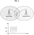
- FIG. 9 is a conceptual view illustrating a CoMP system operated based on a CA environment.
- a carrier operated as a Pcell and a carrier operated as an Scell may use the same frequency band on a frequency axis and are allocated to two eNBs geographically spaced apart from each other.
- a serving eNB of UE1 may be allocated to the Pcell, and a neighboring cell causing much interference may be allocated to the Scell. That is, the eNB of the Pcell and the eNB of the Scell may perform various DL/UL CoMP operations such as joint transmission (JT), CS/CB and dynamic cell selection for one UE.
- JT joint transmission
- CS/CB dynamic cell selection for one UE.
- FIG. 9 illustrates an example that cells managed by two eNBs are aggregated as Pcell and Scell with respect to one UE (e.g., UE1).
- three or more cells may be aggregated.
- some cells of three or more cells may be configured to perform CoMP operation for one UE in the same frequency band, and the other cells may be configured to perform simple CA operation in different frequency bands.
- the Pcell does not always need to participate in CoMP operation.
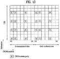
- FIG. 10 illustrates an example of a subframe to which a cell specific reference signal (CRS) that can be used in the embodiments of the present invention is allocated.
- CRS cell specific reference signal
- FIG. 10 illustrates an allocation structure of a CRS if four antennas are supported in a wireless access system.
- the CRS is used for decoding and channel state measurement. Therefore, the CRS is transmitted to all downlink bandwidths at all downlink subframes within a cell supporting PDSCH transmission, and is transmitted from all antenna ports configured in an eNB.
- CRS sequence is mapped to complex-valued modulation symbols used as reference symbols for an antenna port p at a slot ns.
- a UE may measure CSI by using the CRS, and may decode a downlink data signal received through a PDSCH at a subframe including the CRS, by using the CRS. That is, the eNB transmits the CRS from all RBs to a certain position within each RB, and the UE detects a PDSCH after performing channel estimation based on the CRS. For example, the UE measures a signal received at a CRS RE. The UE may detect a PDSCH signal from RE to which PDSCH is mapped, by using a ratio of receiving energy per CRS RE and a receiving energy per RE to which PDSCH is mapped.
- the 3GPP LTE-A system additionally defines UE-specific RS (hereinafter, UE-RS) and channel state information reference signal (CSI-RS) in addition to the CRS.
- UE-RS UE-specific RS
- CSI-RS channel state information reference signal
- the UE-RS and the CRS are used for demodulation, they may be RSs for demodulation in view of use. That is, the UE-RS may be regarded as a kind of a demodulation reference signal (DM-RS). Also, since the CSI-RS and the CRS are used for channel measurement or channel estimation, they may be regarded as RSs for channel state measurement in view of use.
- DM-RS demodulation reference signal
- FIG. 11 illustrates a UE-RS.
- FIG. 11 illustrates REs occupied by UE-RSs among REs in one RB of a normal DL subframe having a normal CP.
- UE-RSs are present and are a valid reference for PDSCH demodulation only if the PDSCH transmission is associated with the corresponding antenna port.
- UE-RSs are transmitted only on RBs to which the corresponding PDSCH is mapped.
- the UE-RSs are configured to be transmitted only on RB(s) to which a PDSCH is mapped in a subframe in which the PDSCH is scheduled unlike CRSs configured to be transmitted in every subframe irrespective of whether the PDSCH is present.
- the UE-RSs are transmitted through antenna port(s) respectively corresponding to layer(s) of a PDSCH unlike CRSs configured to be transmitted through all antenna port(s) irrespective of the number of layer(s) of PDSCH. Accordingly, overhead of the RS may decrease relative to overhead of the CRS.
- Table 6 in the following shows an orthogonal cover code (OCC) used for generating a UE-RS in case of a normal CP.
- OCC orthogonal cover code
- FIG. 12 is a diagram for an example of subframes to which a CSI-RS capable of being used in the embodiments of the present invention is assigned according to the number of antennas.
- a CSI-RS is a DL reference signal introduced to 3GPP LE-A system not to perform demodulation but to measure a state of a radio channel.
- 3GPP LTE-A system defines a plurality of CSI-RS configurations for CSI-RS transmission. In subframes in which CSI-RS transmission is configured, a CSI-RS sequence is mapped according to complex modulation symbols which are used as reference symbols on an antenna port p.
- FIG. 12 (a) shows 20 CSI-RS configurations ranging from 0 to 19 capable of being used for transmitting a CSI-RS by 2 CSI-RS ports among CSI-RS configurations
- FIG. 12 (b) shows 10 CSI-RS configurations ranging from 0 to 9 capable of being used for transmitting a CSI-RS by 4 CSI-RS ports among the CSI-RS configurations
- FIG. 12 (c) shows 5 CSI-RS configurations ranging from 0 to 4 capable of being used for transmitting a CSI-RS by 8 CSI-RS ports among the CSI-RS configurations.
- a CSI-RS port may correspond to an antenna port which is configured for CSI-RS transmission. Since a CSI-RS configuration varies according to the number of CSI-RS ports, although CSI-RS configuration numbers are identical to each other, if the number of antenna ports configured for CSI-RS transmission is different, it can be considered as a different CSI-RS configuration.
- a CSI-RS is configured to be transmitted with a certain transmission period corresponding to a plurality of subframes unlike a CRS configured to be transmitted in every subframe.
- a CSI-RS configuration varies according to not only positions of REs occupied by a CSI-RS in an RB pair but also a subframe to which the CSI-RS is set.
- CSI-RS configuration numbers are identical to each other, if a subframe for CSI-RS transmission is different, it can be considered as a different CSI-RS configuration. For example, if a CSI-RS transmission period (T CSI-RS ) is different or if a start subframe ( ⁇ CSI-RS ) to which CSI-RS transmission is set is different in a radio frame, it can be considered as a different CSI-RS configuration.
- T CSI-RS transmission period
- ⁇ CSI-RS start subframe
- the latter CSI-RS configuration (2) is referred to as a CSI-RS resource configuration.
- the former CSI-RS configuration (1) is referred to as a CSI-RS configuration or a CSI-RS pattern.
- the eNB can inform the UE of information on the number of antennas used for transmitting CSI-RSs, a CSI-RS pattern, a CSI-RS subframe configuration I CSI-RS , UE assumption on reference PDSCH transmitted power for CSI feedback P c , a zero power CSI-RS configuration list, a zero power CSI-RS subframe configuration, and the like.
- the CSI-RS subframe configuration index I CSI-RS corresponds to information for specifying a subframe configuration period T CSI-RS and a subframe offset ⁇ CSI-RS for the occurrence of CSI-RSs.
- Table 7 in the following illustrates the CSI-RS subframe configuration index I CSI-RS according to the T CSI-RS and the ⁇ CSI-RS.
- CSI-RS-SubframeConfig I CSI-RS CSI-RS periodicity T CSI-RS (subframes) CSI-RS subframe offset ⁇ CSI-RS (subframes) 0-4 5 I CSI-RS 5-14 10 I CSI-RS - 5 15-34 20 I CSI-RS - 15 35-74 40 I CSI-RS - 35 75-154 80 I CSI-RS - 75
- a UE configured by a transmission mode defined in a system appearing after 3GPP LTE-A system (e.g., transmission mode 9 or a newly defined transmission mode) the UE performs channel measurement using a CSI-RS and may be able to decode PDSCH using a UE-RS.
- a transmission mode defined in a system appearing after 3GPP LTE-A system e.g., transmission mode 9 or a newly defined transmission mode
- a UE configured by a transmission mode defined in a system appearing after 3GPP LTE-A system (e.g., transmission mode 9 or a newly defined transmission mode) the UE performs channel measurement using a CSI-RS and may be able to decode PDSCH using a UE-RS.
- a transmission mode defined in a system appearing after 3GPP LTE-A system e.g., transmission mode 9 or a newly defined transmission mode
- a cross carrier scheduling (CCS) operation is defined in the following.
- a scheduled CC can be configured to receive DL/UL scheduling from a scheduling CC only.
- the scheduling CC can perform DL/UL scheduling on the scheduling CC itself.
- a search space (SS) for PDCCH which schedules the scheduled CC/scheduling CC in the CCS relation, may exist at control channel regions of all scheduling CCs.
- FDD DL carrier or TDD DL subframes may be able to configure FDD DL carrier or TDD DL subframes to use first n (n ⁇ 4) number of OFDM symbols of each subframe to transmit PDCCH, PHICH, and PCFICH corresponding to physical channels for transmitting various control information and it may be able to configure the remaining OFDM symbols to be used for transmitting PDSCH.
- information on the number of OFD symbols used for transmitting a control channel in each subframe can be transmitted to a UE using a dynamic scheme through such a physical channel as PCFICH or a semi-static scheme through RRC signaling.
- FIG. 13 is a diagram for an example of multiplexing a legacy PDCCH, PDSCH, and E-PDCCH used in LTE/LTE-A system.
- FIGS. 14 to 17 massive MIMO environment is explained.
- FIG. 14 is a diagram for examples of antenna tilting.
- a base station controls a beam transmission direction of an antenna using a mechanical tilting or an electrical tilting.
- the base station reduces inter-cell interference and enhances SINR of UEs in a cell through the antenna tilting.
- the mechanical tilting there is a demerit in that a beam direction is fixed when an antenna is initially installed.
- the electrical titling although a tilting angle is modifiable using a phase shift module, there in a demerit in that it is able to perform very limitative vertical beamforming (vertical beamforming) only.
- FIG. 14 (a) shows a case that the antenna tilting is not performed
- FIG. 14 (b) shows a case that the mechanical tilting is performed
- FIG. 14 (c) shows a case that the electrical tilting (or both the electrical titling and the mechanical tilting) is performed, respectively.
- FIG. 15 is a diagram for an example of implementing an AAS (active antenna system).
- an active antenna system corresponds to a system that each of a plurality of antenna modules includes an RF module including a power amplifier.
- FIG. 15 (b) shows an example of implementing the AAS. Since each antenna module has an active element, each of a plurality of the antenna modules can autonomously control power and a phase.
- a legacy MIMO antenna structure considers a linear structure (i.e., one dimensional array antenna) such as a ULA (uniform linear array).
- a linear structure i.e., one dimensional array antenna
- ULA uniform linear array
- beams capable of being generated by beamforming of antennas exist in a two-dimensional plane. This can also be applied to a legacy PAS-based MIMO structure.
- vertical antenna array and horizontal antenna array exist in the PAS-based MIMO structure, since antennas are controlled by a single RF module, it is difficult to perform beamforming in vertical direction or simple mechanical tilting is available only.
- the AAS-based antenna structure since an RF module is independently installed in every antenna, beamforming is enabled not only in horizontal direction but also in vertical direction. This is called elevation beamforming.
- 3D beamforming that beamforming results of antennas are represented in a 3 dimensional space is enabled.
- the 3 dimensional beamforming is enabled in a manner that one dimensional array antenna structure is evolved to a two dimensional array antenna structure of a plane form.
- the 3 dimensional beamforming can be performed not only in a planar form but also in a conformal ring form in the AAS.
- the 3 dimensional beamforming has a characteristic in that a MIMO process is performed in a 3 dimensional space as an antenna array is evolved to 2D or 3D instead of a legacy straight line.
- FIG. 16 is a diagram for an example of transmitting a UE-specific beam based on AAS.
- the base station is able to perform beamforming.
- the base station is able to perform UE-specific beamforming and transmission.
- FIG. 17 is a diagram for an example of transmitting a 2D beam based on AAS.
- the aforementioned AAS-based 2 dimensional antenna array can be applied not only to a case that an outdoor base station transmits a beam to an outdoor UE but also to environment (O2I, outdoor to indoor) that an outdoor base station transmits a beam to an indoor UE and environment (indoor hotspot) that an indoor base station transmits a beam to an indoor UE.
- environment O2I, outdoor to indoor
- indoor hotspot environment
- the aforementioned contents reflects a fact that it is necessary for a base station to consider not only a beam steering in horizontal direction but also a beam steering in vertical direction in consideration of various terminal heights according to the heights of the buildings.
- the cell environment unlike legacy radio channel environment, it is necessary to additionally consider a change of shade/path loss, a fading characteristic change (LoS/NloS (Line-of-sight/Non-Line-of-sight), DoA (direction of arrival), etc.).
- LoS/NloS Line-of-sight/Non-Line-of-sight
- DoA direction of arrival
- FIGS. 18 and 19 are diagrams for an example of configuring an RS according to embodiments proposed by the present invention.
- the present invention proposes a method of configuring a new RS capable of being applied to a case that transmission of multiple streams of which the number of layers is equal to or greater than 9 is performed.
- the proposed method can be applied to a UE-RS and the method is performed in a manner of multiplexing RS using a legacy UE-RS allocation pattern and a CDM (code division multiplexing) scheme.
- a UE-RS is additionally allocated from a 9 th layer to identically maintain RS density per antenna port with legacy RS density in a frequency axis.
- an antenna port can be additionally defined for a case that the number of layers is equal to or greater than 9.
- An index of a layer and an index of an antenna port can be implemented as shown in Table 8 in the following. [Table 8] Layer index Antenna port index 9 23 10 24 11 25 12 26 13 27 14 28 15 29 16 30
- a layer index is matched with the maximum rank number used by a UE. For example, if a rank used by the UE corresponds to 11, 9 th , 10 th , and 11 th layers correspond to 23 rd , 24th, and 25 th antenna ports, respectively. In this case, 1 st to 8 th layers reuse a legacy antenna port.
- FIG. 18 illustrates an example of mapping an RS to antenna porta 23 to 30 according to the embodiment mentioned earlier in Table 8.
- RSs are mapped to an identical position (i.e., the same RE) in response to antenna ports 23 and 24. By doing so, rank 9/10 transmission has the same RS overhead.
- RSs are mapped to an identical RE in response to antenna ports 25 and 26 and RSs are mapped to an identical RE in response to antenna ports 27 and 28 and antenna ports 29 and 30, respectively.
- RSs for antenna ports 23, 25, 27 and 29 are mapped to a different frequency axis.
- the RSs are distinguished from each other using a FDM (frequency division multiplexing) scheme for the antenna ports 23, 25, 27, and 29 (or antenna ports 24, 26, 28, and 30).
- FDM frequency division multiplexing
- FIG. 19 a method of distinguishing RSs mapped to an identical position is explained via FIG. 19 .
- the RSs for the antenna ports 23, 25, 27, and 29 are distinguished from each other using the FDM scheme.
- RSs corresponding to antenna ports 23 and 24 are mapped to an identical position in a resource region (e.g., subframe).
- a resource region e.g., subframe.
- FIG. 19 shows UE-RSs assigned to a single RB when a UE uses 16 layers.
- REs represented by a diagonal line correspond to REs to which a UE-RS for legacy antenna ports 7 to 14 is assigned.
- two overlapped regions correspond to the proposed REs allocated for the antenna ports 23 to 30.
- the two overlapped regions indicate that a UE-RS, which is generated by a different code, is assigned to a corresponding position.
- UE-RSs of the antenna ports 23 and 24 to which an identical positon is allocated can be distinguished from each other using the CDM scheme in an RB or a subframe.
- UE-REs of the antenna ports 25 and 26, UE-REs of the antenna ports 27 and 28, and UE-REs of the antenna ports 29 and 30 can be distinguished using the CDM scheme.
- a positon of a UE-RS used in the antenna ports 23 to 30 may correspond to 3 rd and 4 th OFDM symbols in a second slot of a subframe.
- the UE-RS can be mapped in a manner that two OFDM symbols contiguous in a time axis are repeated in every 4 subcarriers in response to each antenna port.
- a first reason for selecting the position is that the position is not overlapped with a legacy CRS and a DMRS.
- the positon is overlapped with a legacy CSI-RS, the problem can be solved by dropping the CSI-RS.
- a receiver estimates 2 antenna ports (mapped to an identical RE) multiplexed by the CDM scheme from 2 REs corresponding to a UE-RS.
- a procedure of estimating an antenna port corresponds to a procedure of estimating an effective channel corresponding to the antenna port.
- a UE-RS is assigned to an RE corresponding to 2 adjacent OFDM symbols in time axis, if a moving speed of a UE is slow, channels of two REs are very similar. Hence, when an antenna port of a UE is estimated, it may be able to minimize performance deterioration which occurs when channels of two REs are different from each other.
- a result for an estimated antenna port is interpolated and the interpolated result can be used for an antenna port estimation procedure in a different RE.
- a receiver estimates and obtains 3 antenna port values from 6 REs in response to the antenna port 23 in FIG. 18 and obtains one antenna port value in the entire RB based on the 3 estimated result values. If a moving speed of a UE is fast, an antenna port value may have a significant error depending on an interpolation process and an estimation result. Yet, if the moving speed of the UE is slow, it may be able to estimate an antenna port with sufficiently high accuracy using 2 UE-RS only.
- a procedure of generating a UE-RS is explained in detail. Specifically, a procedure of generating an RS sequence loaded on an RE to which UE-RS of antenna ports 23 to 30 is mapped is explained.
- a sequence (RS sequence) r ( m ) of a UE-RS is defined according to equation 4 described in the following.
- Equation 4 c ( i ) corresponds to an i th element of a pseudo-random sequence and it is defined by ETSI TS 136,211-7.2. Meanwhile, the RS sequence generated by equation 4 is transmitted to a base station as a data symbol defined by equation 5 described in the following.
- k corresponds to a position of a frequency axis
- 1 corresponds to a position of a time axis
- p corresponds to an antenna port
- n PRB corresponds to
- k 4 ⁇ m ′ + N sc RB ⁇ n PRB + k ′
- '4' indicates that the 3 REs are distributed with a space of 4 subcarriers in frequency axis and k' indicates that a position of an RE corresponding to an antenna port moves according to the antenna port in frequency band.
- w p ( i ) corresponds to a code (CDM scheme) for distinguishing two antenna ports mapped to an identical RE position from each other and the code is defined according to Table 9 described in the following.
- Table 9 Antenna port p [ w p (0) w p (1)] 23 [+1 +1] 24 [+1 -1] 25 [-1 -1] 26 [-1 +1] 27 [+1 +1] 28 [+1 -1] 29 [-1 -1] 30 [-1 +1]
- a base station does not assign a UE-RS of the antenna ports. Instead, the base station maps PDSCH to an RE positon corresponding to the UE-RS of the antenna ports 25 to 30 to transmit the PDSCH to the UE.
- the UE-RS is newly defined for the antenna ports 23 to 30 in the foregoing description
- the indexes of the antenna ports are just an example only.
- the method of configuring a UE-Rs proposed in the present invention can also be applied to different antenna port indexes rather than the antenna ports 23 to 30.
- FIG. 20 is a flowchart for a method of configuring an RS proposed by the present invention.
- an RE configuration method according to the aforementioned embodiments is explained in accordance with a time flow.
- content is not explicitly shown or explained in FIG. 20 , it is able to easily aware that the contents mentioned earlier in FIGS. 18 and 19 are identically or similarly applied to FIG. 20 .
- a base station generates a UE-RS [S2010]. As mentioned earlier in equations 4 and 5, this procedure can be performed through a procedure of generating an RS sequence from an initial value. Subsequently, the base station maps the generated UE-RS to a predetermined resource region [S2020]. The resource region to which the UE-RS is mapped is determined in advance according to an index of an antenna port. A mapping relation is determined according to the definition defined by equation 5.
- the UE-RS can be mapped to 3 rd and 4 th OFDM symbols included in a second slot of a subframe.
- UE-RSs can be mapped to one antenna port with a space of 4 subcarriers.
- UE-RSs mapped to 2 adjacent OFDM symbols are repeated three times with an interval of 4 subframes.
- 12 UE-RSs in total are mapped to a subframe.
- two antenna ports are assigned to an identical RE in a subframe.
- UE-RSs corresponding to the two antenna ports are mapped in a manner of being multiplexed using a CDM scheme.
- the base station transmits a subframe to which an RS is mapped to the UE [S2030] and the UE decodes a received data signal [S2040].
- the UE may refer to the UE-RS generated/mapped by the base station.
- FIG. 21 is a block diagram showing the configuration of a user equipment and a bas eseetation according to one embodiment of the present invention.
- a user equipment 100 and the base station 200 may include radio frequency (RF) units 110 and 210, processors 120 and 220 and memories 130 and 230, respectively.
- RF radio frequency
- FIG. 21 a 1:1 communication environment between the user equipment 100 and the base station 200 is shown in FIG. 21 , a communication environment may be established between a plurality of reception module and the transmission module.
- the base station 200 shown in FIG. 21 is applicable to a macro cell base station and a small cell base station.
- the RF units 110 and 210 may include transmitters 112 and 212 and receivers 114 and 214, respectively.
- the transmitter 112 and the receiver 114 of the user equipment 100 are configured to transmit and receive signals to and from the base station 200 and other user equipments and the processor 120 is functionally connected to the transmitter 112 and the receiver 114 to control a process of, at the transmitter 112 and the receiver 114, transmitting and receiving signals to and from other apparatuses.
- the processor 120 processes a signal to be transmitted, sends the processed signal to the transmitter 112 and processes a signal received by the receiver 114.
- the processor 120 may store information included in an exchanged message in the memory 130.
- the user equipment 100 may perform the methods of the various embodiments of the present invention.
- the transmitter 212 and the receiver 214 of the base station 200 are configured to transmit and receive signals to and from another base station and repcetion modules and the processor 220 are functionally connected to the transmitter 212 and the receiver 214 to control a process of, at the transmitter 212 and the receiver 214, transmitting and receiving signals to and from other apparatuses.
- the processor 220 processes a signal to be transmitted, sends the processed signal to the transmitter 212 and processes a signal received by the receiver 214. If necessary, the processor 220 may store information included in an exchanged message in the memory 230.
- the base station 200 may perform the methods of the various embodiments of the present invention.
- the processors 120 and 220 of the user equipment 100 and the base station 200 instruct (for example, control, adjust, or manage) the operations of the user equipment 100 and the base station 200, respectively.
- the processors 120 and 220 may be connected to the memories 130 and 230 for storing program code and data, respectively.
- the memories 130 and 230 are respectively connected to the processors 120 and 220 so as to store operating systems, applications and general files.
- the processors 120 and 220 of the present invention may be called controllers, microcontrollers, microprocessors, microcomputers, etc.
- the processors 120 and 220 may be implemented by hardware, firmware, software, or a combination thereof. If the embodiments of the present invention are implemented by hardware, Application Specific Integrated Circuits (ASICs), Digital Signal Processors (DSPs), Digital Signal Processing Devices (DSPDs), Programmable Logic Devices (PLDs), Field Programmable Gate Arrays (FPGAs), etc. may be included in the processors 120 and 220.
- ASICs Application Specific Integrated Circuits
- DSPs Digital Signal Processors
- DSPDs Digital Signal Processing Devices
- PLDs Programmable Logic Devices
- FPGAs Field Programmable Gate Arrays
- the aforementioned method can be written as computer programs and can be implemented in general-use digital computers that execute the programs using a computer readable recording medium. And, a data structure used for the aforementioned method can be recorded by various means in a computer-readable media.
- Program storing devices usable for explaining a storing device which includes an executable computer code configured to perform various methods of the present invention, should not be understood as a device including such temporary objects as carrier waves and signals.
- the computer-readable media includes such a storing media as a magnetic storing media (e.g., a ROM, a floppy disk, a hard disk and the like) and an optical reading media (e.g., a CD-ROM, a DVD and the like).
Landscapes
- Engineering & Computer Science (AREA)
- Signal Processing (AREA)
- Computer Networks & Wireless Communication (AREA)
- Mobile Radio Communication Systems (AREA)
Claims (14)
- Procédé de génération de signaux de référence spécifiques à un équipement utilisateur, UE, au niveau d'une station de base (200) d'un système de communication sans fil, la station de base comprenant une pluralité d'antennes, le procédé comprenant :générer une séquence de signaux de référence pour une pluralité de ports d'antenne utilisés pour une émission de données, la pluralité de ports d'antenne comprenant plus que 8 ports d'antenne ;mapper la séquence de signaux de référence à une région de ressources allouée respectivement à chacun de la pluralité de ports d'antenne ;générer des signaux de référence spécifiques à un UE respectifs pour chacun de la pluralité des ports d'antenne ; etémettre, à un UE, des signaux de référence spécifiques à un UE de liaison descendante par l'intermédiaire d'une sous-trame sur laquelle la séquence de signaux de référence est mappée pour la pluralité de ports d'antenne,dans lequel une région de ressources pour des signaux de référence spécifiques à un UE pour 8 ports d'antenne parmi la pluralité de ports d'antenne est différente d'une région de ressources pour un ou plusieurs signaux de référence spécifiques à un UE pour les ports d'antenne restants parmi la pluralité de ports d'antenne,dans lequel une région de ressources pour un signal de référence spécifique à un UE pour un neuvième port d'antenne parmi la pluralité de ports d'antenne est identique à une région de ressources pour un signal de référence spécifique à un UE pour un dixième port d'antenne parmi la pluralité de ports d'antenne,dans lequel le signal de référence spécifique à un UE pour le neuvième port d'antenne et le signal de référence spécifique à un UE pour le dixième port d'antenne sont multiplexés sur la base d'une technique de multiplexage par répartition en code, CDM, etdans lequel un canal partagé de liaison descendante physique, PDSCH, est émis par mappage de celui-ci à une région de ressources pour un signal de référence spécifique à un UE pour un port d'antenne non utilisé parmi les ports d'antenne restants inclus dans la pluralité de ports d'antenne.
- Procédé selon la revendication 1, dans lequel la région de ressources pour un ou plusieurs signaux de référence spécifiques à un UE pour les ports d'antenne restants parmi la pluralité de ports d'antenne est définie sur un troisième symbole de multiplexage par répartition orthogonale de la fréquence, OFDM, et un quatrième symbole OFDM d'un second créneau de la sous-trame.
- Procédé selon la revendication 2, dans lequel un signal de référence spécifique à un UE pour chacun des ports d'antenne restants parmi la pluralité de ports d'antenne est mappé à 6 éléments de ressource, RE, totaux sur 3 sous-porteuses agencées avec un espace de 4 sous-porteuses dans les deux symboles OFDM adjacents de la sous-trame.
- Procédé selon la revendication 1, dans lequel les ports d'antenne restants parmi la pluralité de ports d'antenne sont indexés à partir d'un indice de port d'antenne 23 jusqu'à un indice de port d'antenne 30, et dans lequel un indice du neuvième port d'antenne parmi la pluralité de ports d'antenne correspond à 23, et dans lequel un indice du dixième port d'antenne parmi la pluralité de ports d'antenne correspond à 24.
- Procédé selon la revendication 4, dans lequel des signaux de référence spécifiques à un UE pour deux ports d'antenne d'indices de port d'antenne 25 et 26 sont mappés à la même région de ressources et sont multiplexés à l'aide de la technique CDM, dans lequel des signaux de référence spécifiques à un UE pour deux ports d'antenne d'indices de port d'antenne 27 et 28 sont mappés à la même région de ressources et sont multiplexés à l'aide de la technique CDM, et dans lequel des signaux de référence spécifiques à un UE pour deux ports d'antenne d'indices de port d'antenne 29 et 30 sont mappés à la même région de ressources et sont multiplexés à l'aide de la technique CDM.
- Procédé selon la revendication 1, dans lequel les 8 ports d'antenne parmi la pluralité de ports d'antenne sont multiplexés sur la base d'un code de recouvrement orthogonal, OCC, de longueur 4 et les ports d'antenne restants parmi la pluralité de ports d'antenne sont multiplexés sur la base d'un OCC de longueur 2.
- Procédé selon la revendication 4, dans lequel, lorsqu'une région de ressources pour les signaux de référence spécifiques à un UE pour les ports d'antenne restants parmi la pluralité de ports d'antenne se chevauche avec une région de ressources pour un signal de référence d'informations d'état de canal, CSI-RS, qui est mappé, le CSI-RS est abandonné.
- Station de base (200) comprenant une pluralité d'antennes et générant des signaux de référence spécifiques à un équipement utilisateur, UE, dans un système de communication sans fil, la station de base (200) comprenant :une unité d'émission (212) ;une unité de réception (214) ; etun processeur (220) configuré pour générer des signaux de référence spécifiques à un UE d'une manière consistant à être connecté avec l'unité d'émission (212) et à l'unité de réception (214),le processeur (220) étant configuré pour :générer une séquence de signaux de référence pour une pluralité de ports d'antenne utilisés pour une émission de données, la pluralité de ports d'antenne comprenant plus que 8 ports d'antenne ;mapper la séquence de signaux de référence à une région de ressources allouée respectivement à chacun de la pluralité de ports d'antenne ;générer des signaux de référence spécifiques à un UE respectifs pour chacun de la pluralité des ports d'antenne ; etcommander l'unité d'émission (212) pour émettre à l'UE des signaux de référence spécifiques à un UE de liaison descendante par l'intermédiaire d'une sous-trame sur laquelle la séquence de signaux de référence est mappée pour la pluralité de ports d'antenne,dans laquelle une région de ressources pour un signal de référence spécifique à un UE pour un neuvième port d'antenne parmi la pluralité de ports d'antenne est identique à une région de ressources pour un signal de référence spécifique à un UE pour un dixième port d'antenne parmi la pluralité de ports d'antenne,dans laquelle le signal de référence spécifique à un UE pour le neuvième port d'antenne et le signal de référence spécifique à un UE pour le dixième port d'antenne sont multiplexés sur la base d'une technique de multiplexage par répartition en code, CDM, etdans laquelle un canal partagé de liaison descendante physique, PDSCH, est émis par mappage de celui-ci à une région de ressources pour un signal de référence spécifique à un UE pour un port d'antenne non utilisé parmi les ports d'antenne restants inclus dans la pluralité de ports d'antenne.
- Station de base (200) selon la revendication 8, dans laquelle la région de ressources pour un ou plusieurs signaux de référence spécifiques à un UE pour les ports d'antenne restants parmi la pluralité de ports d'antenne est définie sur un troisième symbole de multiplexage par répartition orthogonale de la fréquence, OFDM, et un quatrième symbole OFDM d'un second créneau de la sous-trame.
- Station de base (200) selon la revendication 9, dans laquelle un signal de référence spécifique à un UE pour chacun des ports d'antenne restants parmi la pluralité de ports d'antenne est mappé à 6 éléments de ressource, RE, totaux sur 3 sous-porteuses agencées avec un espace de 4 sous-porteuses dans les deux symboles OFDM adjacents de la sous-trame.
- Station de base (200) selon la revendication 8, dans laquelle les ports d'antenne restants parmi la pluralité de ports d'antenne sont indexés à partir d'un indice de port d'antenne 23 jusqu'à un indice de port d'antenne 30, et dans laquelle un indice du neuvième port d'antenne parmi la pluralité de ports d'antenne correspond à 23, et dans laquelle un indice du dixième port d'antenne parmi la pluralité de ports d'antenne correspond à 24.
- Station de base (200) selon la revendication 11, dans laquelle des signaux de référence spécifiques à un UE pour deux ports d'antenne d'indices de port d'antenne 25 et 26 sont mappés à la même région de ressources et sont multiplexés à l'aide de la technique CDM, dans laquelle des signaux de référence spécifiques à un UE pour deux ports d'antenne d'indices de port d'antenne 27 et 28 sont mappés à la même région de ressources et sont multiplexés à l'aide de la technique CDM,
et dans laquelle des signaux de référence spécifiques à un UE pour deux ports d'antenne d'indices de port d'antenne 29 et 30 sont mappés à la même région de ressources et sont multiplexés à l'aide de la technique CDM. - Station de base (200) selon la revendication 8, dans laquelle les 8 ports d'antenne parmi la pluralité de ports d'antenne sont multiplexés sur la base d'un code de recouvrement orthogonal, OCC, de longueur 4 et les ports d'antenne restants parmi la pluralité de ports d'antenne sont multiplexés sur la base d'un OCC de longueur 2.
- Station de base (200) selon la revendication 11, dans laquelle, lorsqu'une région de ressources pour les signaux de référence spécifiques à un UE pour les ports d'antenne restants parmi la pluralité de ports d'antenne se chevauche avec une région de ressources pour un signal de référence d'informations d'état de canal, CSI-RS, qui est mappé, le CSI-RS est abandonné.
Applications Claiming Priority (2)
| Application Number | Priority Date | Filing Date | Title |
|---|---|---|---|
| US201462062114P | 2014-10-09 | 2014-10-09 | |
| PCT/KR2015/010512 WO2016056805A1 (fr) | 2014-10-09 | 2015-10-05 | Procédé de génération de signaux de référence dans un système de communication sans fil prenant en charge le mimo massif |
Publications (3)
| Publication Number | Publication Date |
|---|---|
| EP3206324A1 EP3206324A1 (fr) | 2017-08-16 |
| EP3206324A4 EP3206324A4 (fr) | 2018-06-20 |
| EP3206324B1 true EP3206324B1 (fr) | 2019-09-04 |
Family
ID=55653363
Family Applications (1)
| Application Number | Title | Priority Date | Filing Date |
|---|---|---|---|
| EP15849231.4A Active EP3206324B1 (fr) | 2014-10-09 | 2015-10-05 | Procédé de génération de signaux de référence dans un système de communication sans fil prenant en charge le mimo massif |
Country Status (5)
| Country | Link |
|---|---|
| US (1) | US10631291B2 (fr) |
| EP (1) | EP3206324B1 (fr) |
| KR (1) | KR102024609B1 (fr) |
| CN (1) | CN107078770B (fr) |
| WO (1) | WO2016056805A1 (fr) |
Families Citing this family (16)
| Publication number | Priority date | Publication date | Assignee | Title |
|---|---|---|---|---|
| JP6721710B2 (ja) * | 2016-03-31 | 2020-07-15 | 華為技術有限公司Huawei Technologies Co.,Ltd. | 参照信号送信方法、参照信号受信方法、装置、及びシステム |
| US10511430B2 (en) | 2016-07-08 | 2019-12-17 | Board Of Regents, The University Of Texas System | Spectrum-agile multiple input multiple output system and capacity adaptation between uplink and downlink |
| US10277514B2 (en) | 2016-07-21 | 2019-04-30 | Viasat, Inc. | Methods and systems for dynamic policy based traffic steering over multiple access networks |
| CN114567932A (zh) * | 2016-09-30 | 2022-05-31 | 华为技术有限公司 | 一种数据传输的方法、相关装置以及系统 |
| CN109617575B (zh) | 2016-12-28 | 2020-06-30 | 上海朗帛通信技术有限公司 | 一种被用于多天线传输的ue、基站中的方法和装置 |
| WO2018151533A1 (fr) | 2017-02-14 | 2018-08-23 | 엘지전자 주식회사 | Procédé de transmission / réception de données dans un système de communication sans fil et appareil correspondant |
| CN108923896B (zh) | 2017-04-19 | 2021-03-26 | 上海朗帛通信技术有限公司 | 一种被用于寻呼的用户设备、基站中的方法和装置 |
| US11026222B2 (en) * | 2017-08-10 | 2021-06-01 | Panasonic Intellectual Property Corporation Of America | User equipment, base station and wireless communication method |
| JP2019050469A (ja) * | 2017-09-08 | 2019-03-28 | シャープ株式会社 | 基地局装置、端末装置、通信方法、および、集積回路 |
| US10707939B2 (en) * | 2017-10-03 | 2020-07-07 | Mediatek Inc. | Codebook-based uplink transmission in wireless communications |
| CN111801917B (zh) * | 2018-01-03 | 2023-05-16 | 瑞典爱立信有限公司 | 用于nr csi-rs的相位跟踪参考信号 |
| CN115378479B (zh) * | 2018-07-13 | 2024-07-30 | 联想(北京)有限公司 | Srs配置和srs传输 |
| CN114342276B (zh) * | 2019-07-24 | 2025-04-04 | 谷歌有限责任公司 | 在通信系统中控制dl mimo传输 |
| CN112350816B (zh) * | 2020-11-12 | 2023-01-17 | 海能达通信股份有限公司 | 一种数据传输方法、存储介质和通信设备 |
| CN115242282B (zh) * | 2022-07-04 | 2024-05-03 | 南京信息技术研究院 | 一种基于dmrs信号的5g nr doa估计方法及估计系统 |
| CN121532991A (zh) * | 2023-05-19 | 2026-02-13 | 华为技术有限公司 | 通信方法和通信装置 |
Family Cites Families (22)
| Publication number | Priority date | Publication date | Assignee | Title |
|---|---|---|---|---|
| US9344259B2 (en) * | 2007-06-20 | 2016-05-17 | Google Technology Holdings LLC | Control channel provisioning and signaling |
| US8885739B2 (en) * | 2009-03-24 | 2014-11-11 | Lg Electronics Inc. | Method and apparatus for transmitting reference signal in wireless communication system |
| US8953563B2 (en) * | 2009-04-24 | 2015-02-10 | Samsung Electronics Co., Ltd. | Method and system for multi-layer beamforming |
| US9288026B2 (en) * | 2009-06-22 | 2016-03-15 | Qualcomm Incorporated | Transmission of reference signal on non-contiguous clusters of resources |
| US8437300B2 (en) * | 2009-10-12 | 2013-05-07 | Samsung Electronics Co., Ltd | Method and system of multi-layer beamforming |
| US9432164B2 (en) * | 2009-10-15 | 2016-08-30 | Qualcomm Incorporated | Method and apparatus for reference signal sequence mapping in wireless communication |
| US8582516B2 (en) * | 2009-11-09 | 2013-11-12 | Qualcomm Incorporated | Reference signaling for a high-mobility wireless communication device |
| KR101789621B1 (ko) | 2010-01-19 | 2017-10-25 | 엘지전자 주식회사 | 하향링크 데이터 전송방법 및 기지국과, 하향링크 데이터 수신방법 및 사용자기기 |
| BR112012016405B1 (pt) * | 2010-01-20 | 2021-06-08 | Telefonaktiebolaget Lm Ericsson (Publ) | método implementado por uma estação base para transmitir sinais de referência de demodulação para um terminal de usuário, método implementado por um terminal de usuário para receber sinais de referência de demodulação transmitidos por uma estação base, estação base, e terminal de usuário |
| KR101783165B1 (ko) * | 2010-06-16 | 2017-09-28 | 텔레호낙티에볼라게트 엘엠 에릭슨(피유비엘) | 기준 신호를 전송 및 디코딩하기 위한 방법 및 장치 |
| JP2012114901A (ja) * | 2010-11-05 | 2012-06-14 | Sharp Corp | 移動局装置、基地局装置、方法および集積回路 |
| US8964663B2 (en) * | 2011-01-06 | 2015-02-24 | Qualcomm Incorporated | Method and apparatus for signaling paging configurations and channel state information reference signal (CSI-RS) configurations |
| WO2013009702A1 (fr) * | 2011-07-08 | 2013-01-17 | Huawei Technologies Co., Ltd. | Système et procédé de communication de signaux de référence |
| US9197387B2 (en) * | 2011-08-15 | 2015-11-24 | Google Technology Holdings LLC | Method and apparatus for control channel transmission and reception |
| US20130064216A1 (en) * | 2011-09-12 | 2013-03-14 | Research In Motion Limited | DMRS Association and Signaling for Enhanced PDCCH in LTE Systems |
| WO2013062231A1 (fr) | 2011-10-24 | 2013-05-02 | Lg Electronics Inc. | Procédé et appareil d'attribution de ressources dans un système de communications sans fil |
| JP5843390B2 (ja) * | 2011-12-12 | 2016-01-13 | シャープ株式会社 | 通信システム、移動局装置、基地局装置、通信方法および集積回路 |
| US9161241B2 (en) | 2012-03-30 | 2015-10-13 | Nokia Solutions And Networks Oy | Reference signal design and signaling for per-user elevation MIMO |
| US9794817B2 (en) | 2012-06-24 | 2017-10-17 | Lg Electronics Inc. | Method and apparatus for reporting channel state information in wireless communication system |
| EP2893660B1 (fr) * | 2012-09-05 | 2018-12-12 | LG Electronics Inc. | Procédé et appareil d'émission de signal de liaison descendante dans un système de communication sans fil |
| KR101987232B1 (ko) * | 2012-11-02 | 2019-09-30 | 주식회사 팬택 | 다중 안테나 시스템에서 참조 신호의 전송장치 및 방법 |
| JP6114153B2 (ja) * | 2013-09-26 | 2017-04-12 | 株式会社Nttドコモ | 基地局、移動局、参照信号送信方法及びチャネル品質測定方法 |
-
2015
- 2015-10-05 WO PCT/KR2015/010512 patent/WO2016056805A1/fr not_active Ceased
- 2015-10-05 EP EP15849231.4A patent/EP3206324B1/fr active Active
- 2015-10-05 KR KR1020177003518A patent/KR102024609B1/ko active Active
- 2015-10-05 US US15/515,096 patent/US10631291B2/en active Active
- 2015-10-05 CN CN201580051325.5A patent/CN107078770B/zh active Active
Non-Patent Citations (1)
| Title |
|---|
| None * |
Also Published As
| Publication number | Publication date |
|---|---|
| KR102024609B1 (ko) | 2019-11-04 |
| US20170245271A1 (en) | 2017-08-24 |
| EP3206324A4 (fr) | 2018-06-20 |
| CN107078770B (zh) | 2020-10-16 |
| US10631291B2 (en) | 2020-04-21 |
| WO2016056805A1 (fr) | 2016-04-14 |
| EP3206324A1 (fr) | 2017-08-16 |
| KR20170030588A (ko) | 2017-03-17 |
| CN107078770A (zh) | 2017-08-18 |
Similar Documents
| Publication | Publication Date | Title |
|---|---|---|
| EP3206324B1 (fr) | Procédé de génération de signaux de référence dans un système de communication sans fil prenant en charge le mimo massif | |
| US11357021B2 (en) | Method for transceiving enhanced physical downlink control channel in wireless access system supporting unlicensed band, and device supporting same | |
| US10356645B2 (en) | Method for radio resource measurement in wireless access system supporting carrier aggregation, and apparatus supporting same | |
| US9614653B2 (en) | Method and apparatus for performing Quasi Co-Location in wireless access system | |
| US9520973B2 (en) | Method for transmitting reference signal to antenna port in wireless access system | |
| EP3177096B1 (fr) | Procédé et dispositif pour configurer une période d'opportunité d'émission dans un système d'accès sans fil prenant en charge une bande non autorisée | |
| US10349294B2 (en) | Efficient relay transmission method and device in wireless access system supporting device to device communication | |
| US10862607B2 (en) | Method for transceiving shortened physical downlink shared channel in wireless access system supporting unlicensed band, and device supporting same | |
| US10517070B2 (en) | Method and devices for selecting transmission resource in wireless access system supporting non-licensed band | |
| US10425211B2 (en) | Method for measuring and reporting channel state in wireless access system supporting unlicensed band | |
| EP3383101B1 (fr) | Procédé et appareil de commande de puissance dans un système d'accès sans fil | |
| EP3823408A1 (fr) | Procédé d'exécution de cca dans un système d'accès sans fil prenant en charge une bande sans licence et appareil le prenant en charge | |
| EP3174333B1 (fr) | Appareil et procédé pour relayer des données dans un système d'accès sans fil prenant en charge la communication de dispositif à dispositif | |
| US10117269B2 (en) | Method and device for transmitting and receiving data in wireless access system supporting unlicensed band | |
| US9860886B2 (en) | Methods and devices for transceiving/transmitting downlink data in wireless access system supporting new carrier type |
Legal Events
| Date | Code | Title | Description |
|---|---|---|---|
| STAA | Information on the status of an ep patent application or granted ep patent |
Free format text: STATUS: THE INTERNATIONAL PUBLICATION HAS BEEN MADE |
|
| PUAI | Public reference made under article 153(3) epc to a published international application that has entered the european phase |
Free format text: ORIGINAL CODE: 0009012 |
|
| STAA | Information on the status of an ep patent application or granted ep patent |
Free format text: STATUS: REQUEST FOR EXAMINATION WAS MADE |
|
| 17P | Request for examination filed |
Effective date: 20170426 |
|
| AK | Designated contracting states |
Kind code of ref document: A1 Designated state(s): AL AT BE BG CH CY CZ DE DK EE ES FI FR GB GR HR HU IE IS IT LI LT LU LV MC MK MT NL NO PL PT RO RS SE SI SK SM TR |
|
| AX | Request for extension of the european patent |
Extension state: BA ME |
|
| DAV | Request for validation of the european patent (deleted) | ||
| DAX | Request for extension of the european patent (deleted) | ||
| A4 | Supplementary search report drawn up and despatched |
Effective date: 20180523 |
|
| RIC1 | Information provided on ipc code assigned before grant |
Ipc: H04B 7/06 20060101ALI20180516BHEP Ipc: H04L 27/26 20060101ALI20180516BHEP Ipc: H04W 72/04 20090101ALI20180516BHEP Ipc: H04L 5/00 20060101AFI20180516BHEP |
|
| GRAP | Despatch of communication of intention to grant a patent |
Free format text: ORIGINAL CODE: EPIDOSNIGR1 |
|
| STAA | Information on the status of an ep patent application or granted ep patent |
Free format text: STATUS: GRANT OF PATENT IS INTENDED |
|
| INTG | Intention to grant announced |
Effective date: 20190410 |
|
| GRAS | Grant fee paid |
Free format text: ORIGINAL CODE: EPIDOSNIGR3 |
|
| GRAA | (expected) grant |
Free format text: ORIGINAL CODE: 0009210 |
|
| STAA | Information on the status of an ep patent application or granted ep patent |
Free format text: STATUS: THE PATENT HAS BEEN GRANTED |
|
| AK | Designated contracting states |
Kind code of ref document: B1 Designated state(s): AL AT BE BG CH CY CZ DE DK EE ES FI FR GB GR HR HU IE IS IT LI LT LU LV MC MK MT NL NO PL PT RO RS SE SI SK SM TR |
|
| REG | Reference to a national code |
Ref country code: GB Ref legal event code: FG4D |
|
| REG | Reference to a national code |
Ref country code: CH Ref legal event code: EP |
|
| REG | Reference to a national code |
Ref country code: AT Ref legal event code: REF Ref document number: 1176883 Country of ref document: AT Kind code of ref document: T Effective date: 20190915 |
|
| REG | Reference to a national code |
Ref country code: DE Ref legal event code: R096 Ref document number: 602015037462 Country of ref document: DE |
|
| REG | Reference to a national code |
Ref country code: IE Ref legal event code: FG4D |
|
| REG | Reference to a national code |
Ref country code: NL Ref legal event code: MP Effective date: 20190904 |
|
| REG | Reference to a national code |
Ref country code: LT Ref legal event code: MG4D |
|
| PG25 | Lapsed in a contracting state [announced via postgrant information from national office to epo] |
Ref country code: FI Free format text: LAPSE BECAUSE OF FAILURE TO SUBMIT A TRANSLATION OF THE DESCRIPTION OR TO PAY THE FEE WITHIN THE PRESCRIBED TIME-LIMIT Effective date: 20190904 Ref country code: SE Free format text: LAPSE BECAUSE OF FAILURE TO SUBMIT A TRANSLATION OF THE DESCRIPTION OR TO PAY THE FEE WITHIN THE PRESCRIBED TIME-LIMIT Effective date: 20190904 Ref country code: BG Free format text: LAPSE BECAUSE OF FAILURE TO SUBMIT A TRANSLATION OF THE DESCRIPTION OR TO PAY THE FEE WITHIN THE PRESCRIBED TIME-LIMIT Effective date: 20191204 Ref country code: NO Free format text: LAPSE BECAUSE OF FAILURE TO SUBMIT A TRANSLATION OF THE DESCRIPTION OR TO PAY THE FEE WITHIN THE PRESCRIBED TIME-LIMIT Effective date: 20191204 Ref country code: LT Free format text: LAPSE BECAUSE OF FAILURE TO SUBMIT A TRANSLATION OF THE DESCRIPTION OR TO PAY THE FEE WITHIN THE PRESCRIBED TIME-LIMIT Effective date: 20190904 Ref country code: HR Free format text: LAPSE BECAUSE OF FAILURE TO SUBMIT A TRANSLATION OF THE DESCRIPTION OR TO PAY THE FEE WITHIN THE PRESCRIBED TIME-LIMIT Effective date: 20190904 |
|
| PG25 | Lapsed in a contracting state [announced via postgrant information from national office to epo] |
Ref country code: RS Free format text: LAPSE BECAUSE OF FAILURE TO SUBMIT A TRANSLATION OF THE DESCRIPTION OR TO PAY THE FEE WITHIN THE PRESCRIBED TIME-LIMIT Effective date: 20190904 Ref country code: LV Free format text: LAPSE BECAUSE OF FAILURE TO SUBMIT A TRANSLATION OF THE DESCRIPTION OR TO PAY THE FEE WITHIN THE PRESCRIBED TIME-LIMIT Effective date: 20190904 Ref country code: GR Free format text: LAPSE BECAUSE OF FAILURE TO SUBMIT A TRANSLATION OF THE DESCRIPTION OR TO PAY THE FEE WITHIN THE PRESCRIBED TIME-LIMIT Effective date: 20191205 Ref country code: ES Free format text: LAPSE BECAUSE OF FAILURE TO SUBMIT A TRANSLATION OF THE DESCRIPTION OR TO PAY THE FEE WITHIN THE PRESCRIBED TIME-LIMIT Effective date: 20190904 Ref country code: AL Free format text: LAPSE BECAUSE OF FAILURE TO SUBMIT A TRANSLATION OF THE DESCRIPTION OR TO PAY THE FEE WITHIN THE PRESCRIBED TIME-LIMIT Effective date: 20190904 |
|
| REG | Reference to a national code |
Ref country code: AT Ref legal event code: MK05 Ref document number: 1176883 Country of ref document: AT Kind code of ref document: T Effective date: 20190904 |
|
| PG25 | Lapsed in a contracting state [announced via postgrant information from national office to epo] |
Ref country code: EE Free format text: LAPSE BECAUSE OF FAILURE TO SUBMIT A TRANSLATION OF THE DESCRIPTION OR TO PAY THE FEE WITHIN THE PRESCRIBED TIME-LIMIT Effective date: 20190904 Ref country code: IT Free format text: LAPSE BECAUSE OF FAILURE TO SUBMIT A TRANSLATION OF THE DESCRIPTION OR TO PAY THE FEE WITHIN THE PRESCRIBED TIME-LIMIT Effective date: 20190904 Ref country code: AT Free format text: LAPSE BECAUSE OF FAILURE TO SUBMIT A TRANSLATION OF THE DESCRIPTION OR TO PAY THE FEE WITHIN THE PRESCRIBED TIME-LIMIT Effective date: 20190904 Ref country code: NL Free format text: LAPSE BECAUSE OF FAILURE TO SUBMIT A TRANSLATION OF THE DESCRIPTION OR TO PAY THE FEE WITHIN THE PRESCRIBED TIME-LIMIT Effective date: 20190904 Ref country code: PL Free format text: LAPSE BECAUSE OF FAILURE TO SUBMIT A TRANSLATION OF THE DESCRIPTION OR TO PAY THE FEE WITHIN THE PRESCRIBED TIME-LIMIT Effective date: 20190904 Ref country code: RO Free format text: LAPSE BECAUSE OF FAILURE TO SUBMIT A TRANSLATION OF THE DESCRIPTION OR TO PAY THE FEE WITHIN THE PRESCRIBED TIME-LIMIT Effective date: 20190904 Ref country code: PT Free format text: LAPSE BECAUSE OF FAILURE TO SUBMIT A TRANSLATION OF THE DESCRIPTION OR TO PAY THE FEE WITHIN THE PRESCRIBED TIME-LIMIT Effective date: 20200106 |
|
| PG25 | Lapsed in a contracting state [announced via postgrant information from national office to epo] |
Ref country code: CZ Free format text: LAPSE BECAUSE OF FAILURE TO SUBMIT A TRANSLATION OF THE DESCRIPTION OR TO PAY THE FEE WITHIN THE PRESCRIBED TIME-LIMIT Effective date: 20190904 Ref country code: SK Free format text: LAPSE BECAUSE OF FAILURE TO SUBMIT A TRANSLATION OF THE DESCRIPTION OR TO PAY THE FEE WITHIN THE PRESCRIBED TIME-LIMIT Effective date: 20190904 Ref country code: SM Free format text: LAPSE BECAUSE OF FAILURE TO SUBMIT A TRANSLATION OF THE DESCRIPTION OR TO PAY THE FEE WITHIN THE PRESCRIBED TIME-LIMIT Effective date: 20190904 Ref country code: IS Free format text: LAPSE BECAUSE OF FAILURE TO SUBMIT A TRANSLATION OF THE DESCRIPTION OR TO PAY THE FEE WITHIN THE PRESCRIBED TIME-LIMIT Effective date: 20200224 |
|
| REG | Reference to a national code |
Ref country code: CH Ref legal event code: PL |
|
| REG | Reference to a national code |
Ref country code: DE Ref legal event code: R097 Ref document number: 602015037462 Country of ref document: DE |
|
| PLBE | No opposition filed within time limit |
Free format text: ORIGINAL CODE: 0009261 |
|
| STAA | Information on the status of an ep patent application or granted ep patent |
Free format text: STATUS: NO OPPOSITION FILED WITHIN TIME LIMIT |
|
| PG2D | Information on lapse in contracting state deleted |
Ref country code: IS |
|
| PG25 | Lapsed in a contracting state [announced via postgrant information from national office to epo] |
Ref country code: DK Free format text: LAPSE BECAUSE OF FAILURE TO SUBMIT A TRANSLATION OF THE DESCRIPTION OR TO PAY THE FEE WITHIN THE PRESCRIBED TIME-LIMIT Effective date: 20190904 Ref country code: LU Free format text: LAPSE BECAUSE OF NON-PAYMENT OF DUE FEES Effective date: 20191005 Ref country code: LI Free format text: LAPSE BECAUSE OF NON-PAYMENT OF DUE FEES Effective date: 20191031 Ref country code: CH Free format text: LAPSE BECAUSE OF NON-PAYMENT OF DUE FEES Effective date: 20191031 Ref country code: IS Free format text: LAPSE BECAUSE OF FAILURE TO SUBMIT A TRANSLATION OF THE DESCRIPTION OR TO PAY THE FEE WITHIN THE PRESCRIBED TIME-LIMIT Effective date: 20200105 |
|
| 26N | No opposition filed |
Effective date: 20200605 |
|
| REG | Reference to a national code |
Ref country code: BE Ref legal event code: MM Effective date: 20191031 |
|
| PG25 | Lapsed in a contracting state [announced via postgrant information from national office to epo] |
Ref country code: MC Free format text: LAPSE BECAUSE OF FAILURE TO SUBMIT A TRANSLATION OF THE DESCRIPTION OR TO PAY THE FEE WITHIN THE PRESCRIBED TIME-LIMIT Effective date: 20190904 Ref country code: BE Free format text: LAPSE BECAUSE OF NON-PAYMENT OF DUE FEES Effective date: 20191031 Ref country code: SI Free format text: LAPSE BECAUSE OF FAILURE TO SUBMIT A TRANSLATION OF THE DESCRIPTION OR TO PAY THE FEE WITHIN THE PRESCRIBED TIME-LIMIT Effective date: 20190904 |
|
| GBPC | Gb: european patent ceased through non-payment of renewal fee |
Effective date: 20191204 |
|
| PG25 | Lapsed in a contracting state [announced via postgrant information from national office to epo] |
Ref country code: FR Free format text: LAPSE BECAUSE OF NON-PAYMENT OF DUE FEES Effective date: 20191104 Ref country code: IE Free format text: LAPSE BECAUSE OF NON-PAYMENT OF DUE FEES Effective date: 20191005 Ref country code: GB Free format text: LAPSE BECAUSE OF NON-PAYMENT OF DUE FEES Effective date: 20191204 |
|
| PG25 | Lapsed in a contracting state [announced via postgrant information from national office to epo] |
Ref country code: CY Free format text: LAPSE BECAUSE OF FAILURE TO SUBMIT A TRANSLATION OF THE DESCRIPTION OR TO PAY THE FEE WITHIN THE PRESCRIBED TIME-LIMIT Effective date: 20190904 |
|
| PG25 | Lapsed in a contracting state [announced via postgrant information from national office to epo] |
Ref country code: MT Free format text: LAPSE BECAUSE OF FAILURE TO SUBMIT A TRANSLATION OF THE DESCRIPTION OR TO PAY THE FEE WITHIN THE PRESCRIBED TIME-LIMIT Effective date: 20190904 Ref country code: HU Free format text: LAPSE BECAUSE OF FAILURE TO SUBMIT A TRANSLATION OF THE DESCRIPTION OR TO PAY THE FEE WITHIN THE PRESCRIBED TIME-LIMIT; INVALID AB INITIO Effective date: 20151005 |
|
| PG25 | Lapsed in a contracting state [announced via postgrant information from national office to epo] |
Ref country code: TR Free format text: LAPSE BECAUSE OF FAILURE TO SUBMIT A TRANSLATION OF THE DESCRIPTION OR TO PAY THE FEE WITHIN THE PRESCRIBED TIME-LIMIT Effective date: 20190904 |
|
| PG25 | Lapsed in a contracting state [announced via postgrant information from national office to epo] |
Ref country code: MK Free format text: LAPSE BECAUSE OF FAILURE TO SUBMIT A TRANSLATION OF THE DESCRIPTION OR TO PAY THE FEE WITHIN THE PRESCRIBED TIME-LIMIT Effective date: 20190904 |
|
| PGFP | Annual fee paid to national office [announced via postgrant information from national office to epo] |
Ref country code: DE Payment date: 20250908 Year of fee payment: 11 |