EP3206353B1 - Filterbänke und verfahren zum betreiben von filterbänken - Google Patents
Filterbänke und verfahren zum betreiben von filterbänken Download PDFInfo
- Publication number
- EP3206353B1 EP3206353B1 EP16154802.9A EP16154802A EP3206353B1 EP 3206353 B1 EP3206353 B1 EP 3206353B1 EP 16154802 A EP16154802 A EP 16154802A EP 3206353 B1 EP3206353 B1 EP 3206353B1
- Authority
- EP
- European Patent Office
- Prior art keywords
- module
- filter
- signals
- received
- filter modules
- Prior art date
- Legal status (The legal status is an assumption and is not a legal conclusion. Google has not performed a legal analysis and makes no representation as to the accuracy of the status listed.)
- Active
Links
- 238000000034 method Methods 0.000 title claims description 18
- 230000015572 biosynthetic process Effects 0.000 claims description 32
- 238000003786 synthesis reaction Methods 0.000 claims description 32
- 230000004044 response Effects 0.000 claims description 13
- 230000000295 complement effect Effects 0.000 claims description 10
- 238000012545 processing Methods 0.000 claims description 10
- 230000003111 delayed effect Effects 0.000 claims description 4
- 230000008569 process Effects 0.000 claims description 4
- 230000001131 transforming effect Effects 0.000 claims description 4
- 230000001268 conjugating effect Effects 0.000 claims 2
- 238000000354 decomposition reaction Methods 0.000 description 22
- 230000006870 function Effects 0.000 description 16
- 238000012546 transfer Methods 0.000 description 14
- 238000005070 sampling Methods 0.000 description 5
- 239000011159 matrix material Substances 0.000 description 4
- 230000009467 reduction Effects 0.000 description 4
- 238000004891 communication Methods 0.000 description 3
- 238000001914 filtration Methods 0.000 description 3
- 238000005457 optimization Methods 0.000 description 3
- 238000013461 design Methods 0.000 description 2
- 238000011161 development Methods 0.000 description 2
- 230000014509 gene expression Effects 0.000 description 2
- 238000013507 mapping Methods 0.000 description 2
- 238000001228 spectrum Methods 0.000 description 2
- 239000013598 vector Substances 0.000 description 2
- 101150012579 ADSL gene Proteins 0.000 description 1
- 102100020775 Adenylosuccinate lyase Human genes 0.000 description 1
- 108700040193 Adenylosuccinate lyases Proteins 0.000 description 1
- 238000003775 Density Functional Theory Methods 0.000 description 1
- 230000003044 adaptive effect Effects 0.000 description 1
- 230000001364 causal effect Effects 0.000 description 1
- 230000001413 cellular effect Effects 0.000 description 1
- 230000006835 compression Effects 0.000 description 1
- 238000007906 compression Methods 0.000 description 1
- 239000012141 concentrate Substances 0.000 description 1
- 125000004122 cyclic group Chemical group 0.000 description 1
- 230000001419 dependent effect Effects 0.000 description 1
- 238000005516 engineering process Methods 0.000 description 1
- 238000012886 linear function Methods 0.000 description 1
- 238000010295 mobile communication Methods 0.000 description 1
- 230000000737 periodic effect Effects 0.000 description 1
- 238000013139 quantization Methods 0.000 description 1
- 230000003595 spectral effect Effects 0.000 description 1
Images






Classifications
-
- H—ELECTRICITY
- H04—ELECTRIC COMMUNICATION TECHNIQUE
- H04L—TRANSMISSION OF DIGITAL INFORMATION, e.g. TELEGRAPHIC COMMUNICATION
- H04L27/00—Modulated-carrier systems
- H04L27/26—Systems using multi-frequency codes
- H04L27/2601—Multicarrier modulation systems
- H04L27/2647—Arrangements specific to the receiver only
- H04L27/2649—Demodulators
- H04L27/26534—Pulse-shaped multi-carrier, i.e. not using rectangular window
- H04L27/2654—Filtering per subcarrier, e.g. filterbank multicarrier [FBMC]
-
- H—ELECTRICITY
- H04—ELECTRIC COMMUNICATION TECHNIQUE
- H04L—TRANSMISSION OF DIGITAL INFORMATION, e.g. TELEGRAPHIC COMMUNICATION
- H04L27/00—Modulated-carrier systems
- H04L27/26—Systems using multi-frequency codes
- H04L27/2601—Multicarrier modulation systems
- H04L27/2626—Arrangements specific to the transmitter only
- H04L27/2627—Modulators
- H04L27/264—Pulse-shaped multi-carrier, i.e. not using rectangular window
- H04L27/26416—Filtering per subcarrier, e.g. filterbank multicarrier [FBMC]
Definitions
- the disclosure relates to filter banks and methods for operating filter banks.
- FBs Filter banks
- DSP digital signal processing
- AFB Analysis Filter Bank
- SBC Sub-band Coding
- the second configuration is the so called transmultiplexer (TMUX) and it is mainly applied to wired and wireless communications systems, where a number of data streams of one or more users are combined into one broadband signal to be transmitted via some medium and in the receiver, the different streams are then recovered.
- Modulated Filter Banks are between the most popular FB classes because they have implementation structures with very low computational complexity.
- MFBs multicarrier modulation schemes. Those schemes are frequently called Filter Bank based Multicarrier (FBMC).
- FBMC Filter Bank based Multicarrier
- OFDM Orthogonal Frequency Division Multiplexing
- OFDM utilizes a trivial prototype filter (all ones) and does not achieve maximum spectral efficiency due to the cyclic prefix.
- OFDM has been used in different wired and wireless standards, like ADSL, VDSL, WiFi and LTE, the 4th Generation of cellular systems. In the discussions of future mobile communications standards, more specifically the 5th Generation (5G), more general implementations of FBMC systems are under consideration.
- One of the candidate schemes is FBMC with the symbols in each subcarrier using Offset Quadrature Amplitude Modulation (OQAM) mapping.
- OFDM Offset Quadrature Amplitude Modulation
- a synthesis filter bank according to claim 1 an analysis filter bank according to claim 4, a filter bank according to claim 6, a method for operating a synthesis filter bank according to claim 7 and a method for operating an analysis filter bank according to claim 8 are provided. Further embodiments are subject matter of dependent claims.
- a synthesis filter bank comprises a transform module which is configured to receive a plurality of input signals, transform the plurality of input signals, and output a plurality of transformed signals, a plurality of filter modules, which are coupled to the transform module, and wherein each filter module of the plurality of filter modules is configured to receive two transformed signals from the transform module, process the two received transformed signals and output two processed signals, and a parallel-to-serial module which is coupled to the plurality of filter modules and which is configured to receive the processed signals from the plurality of filter modules, combine the received processed signals and output a combined signal.
- an analysis filter bank comprises a serial-to-parallel module which is configured to receive an input signal and divide the received input signal into a plurality of output signals, a plurality of filter modules which are coupled to the serial-to-parallel module, wherein each filter module of the plurality of filter modules is configured to receive two output signals from the serial-to-parallel module, process the two received output signals and output two processed signals, and a transform module which is coupled to the plurality of filter modules and which is configured to receive the processed signals, transform the plurality of processed signals, and output a plurality of transformed signals.
- a filter bank comprising a synthesis filter and an analysis filter bank.
- the analysis filter bank and the synthesis filter bank can be arranged in any order in the filter bank.
- a synthesis filter bank may receive a plurality of input signals.
- An output of the synthesis filter bank can be provided as input to the analysis filter bank which outputs a plurality of signals.
- an input may be first received by the analysis filter bank, and the outputs of the analysis filter bank may be provided as inputs to the synthesis filter bank in order to output a signal.
- a method for operating a synthesis filter bank comprising: receiving a plurality of input signals by a transform module, transforming, by the transform module, the plurality of input signals, outputting, by the transform module, a plurality of transformed signals, receiving, by a plurality of filter modules which are coupled to the transform module, the plurality of transformed signals, wherein each filter module of the plurality of filter modules is configured to receive two transformed signals from the transform module, processing, by each of the plurality of filter modules, the two received transformed signals, outputting, by each of the plurality of filter modules, two processed signals, receiving, by a parallel-to-serial module which is coupled to the plurality of filter modules, the processed signals, combining, by the parallel-to-serial module, the received processed signals, and outputting, by the parallel-to-serial module, a combined signal.
- a method for operating an analysis filter bank comprising: receiving, by a serial-to-parallel module, an input signal, dividing, by the serial-to-parallel module, the received input signal into a plurality of output signals, receiving, by a plurality of filter modules which are coupled to the serial-to-parallel module, the plurality of output signals, wherein each filter module of the plurality of filter modules is configured to receive two output signals from the serial-to-parallel module, processing, by each of the plurality of filter modules, the two received output signals, outputting, by each of the plurality of filter modules, two processed signals, receiving, by a transform module which is coupled to the plurality of filter modules, the processed signals, transforming, by the transform module, the plurality of processed signals, and outputting, by the transform module, a plurality of transformed signals.
- the plurality of filter modules may be designed from an orthogonal prototype filter, wherein each filter module comprises a first filter and a second filter, wherein the second filter is a power complementary filter of the first filter such that the two received transformed signals are processed simultaneously.
- the filter modules may be implemented as a finite impulse response filter. In this case a single finite impulse response (FIR) low-pass filter, the so-called prototype filter, needs to be designed and the other filters of the plurality of filter modules can be obtained by decomposing it in its polyphase components, which can be from types 1, 2 or 3.
- the prototype filter may be a prototype filter with linear phase, i.e. with symmetrical impulse response.
- the transform module may be configured to provide a linear transform of the received signals.
- the transform module may be a Fourier transform module configured to perform a discrete Fourier transform (DFT) of received signals in a computationally efficient manner, for example by employing a fast Fourier transform (FFT) algorithm.
- the transform module may be an inverse Fourier transform module configured to perform an inverse discrete Fourier transform (IDFT) of received signals in a computationally efficient manner, for example by employing an inverse fast Fourier transform (IFFT) algorithm.
- IDFT inverse discrete Fourier transform
- IFFT inverse fast Fourier transform
- the polyphase decomposition is of type 1
- an inverse Fourier transform module may be employed in the synthesis and / or analysis filter bank.
- a Fourier transform module may be employed in the synthesis and / or analysis filter bank.
- the synthesis filter bank and / or the analysis filter bank may be configured to receive a digital signal which may be represented by a complex number.
- the digital signal may contain samples which may be real numbers, like voice, audio, images or videos.
- a real valued prototype filter may be modulated either with sines or cosines. It is worth noting that a prototype filter may be real valued and a modulation of it may be complex valued.
- the information to be transmitted usually modulates the amplitude and the phase of a carrier wave.
- the digital signal may be represented by complex numbers to convey both amplitude and phase information.
- one of the two processed signals may be complex conjugated before it is received by the parallel-to-serial module.
- a negative sign may applied to one of the two processed signals before it is received by the parallel-to-serial module, e.g. by multiplying the signal with a factor (-1) m +1 , wherein m is the time index.
- a sign of the processed signal which is complex conjugated may be turned negative before it is received by the parallel-to-serial module.
- a number of the transformed signals which are received by the plurality of filter modules of the synthesis filter bank may be half the number of input signals received by the transform module.
- one of the two transformed signals may be delayed in time before being received by the respective filter module, e.g. by T/2, wherein 1/T is the sampling rate.
- an output signal may be complex conjugated before it is received by the respective filter module.
- a negative sign may be applied to one of the two output signals before it is received by the respective filter module, e.g. by multiplying the signal with a factor (-1) m +1 , wherein m is the time index.
- one of the two processed signals may be delayed in time before being received by the serial-to-parallel module, e.g. by T /2, wherein 1/ T is the sampling rate.
- H k (z) and F k (z) are obtained by exponentially modulating H P (z) :
- h k l h P l W M ⁇ k l ⁇ P ⁇ 1 2 .
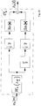
- the block O k in the SFB performs a T 2 staggering of the real and imaginary parts of the low-rate signals x k [l] and is frequently called OQAM-staggering, -modulation or -mapping.
- Fig. 3 depicts the internal structure of O k for sub-channels with even k and Fig. 4 for odd k, where the Re ⁇ • ⁇ and jIm ⁇ • ⁇ blocks are simply exchanged.
- the filtered signals at the AFB are downsampled by the block ⁇ M 2 that removes M 2 ⁇ 1 samples and lowers the rate by a factor M 2 .
- the block O k ′ represents the OQAM or real and imaginary de-staggering.
- Fig. 5 shows the OQAM-de-staggering operation for sub-channels with even k and Fig. 6 for odd k.
- the DFT or IDFT can be efficiently implemented using Fast Fourier Transform (FFT) algorithms.
- FFT Fast Fourier Transform
- the equations can be further developed with the application of the Nobble identities and combined with the OQAM staggering to come up with the structure in Fig. 7 .
- the prototype filter Hp(z) is designed such that perfect reconstruction (PR) conditions are fulfilled.
- PR perfect reconstruction
- the prototype FIR filter has linear phase and, consequently, symmetrical impulse response.
- the prototype coefficients For the cases where K > 2 there is no closed form solution to directly obtain the prototype coefficients.
- One possibility is to obtain the prototype by numerical optimization methods. Given a certain design criteria for the optimization of H P (z), e.g. minimization of the stopband energy, the M 4 equations can be employed in a constrained optimization method. It is worth noting that the constraints are non-linear relations on the prototype filter coefficients. The typical objective function will usually also be a non-linear function of the prototype coefficients. It is worth noting that although the prototype has a symmetrical impulse response, necessary to achieve PR, one multiplier per prototype filter coefficient has to be realized in the polyphase network.
- Fig. 8 it is necessary to reorganize the IDFT outputs. Moreover, for each polyphase component pair the outputs are added at the lower sampling rate. The delay that is necessary for the output of the polyphase component with highest index in each pair is transferred to the lower sampling rate and then to the front of the filter block. Finally, the outputs of the polyphase components pairs in Fig. 8 are serialized, different to Fig.7 where instead of being directly serialized the outputs of the two power complementary polyphase components are added at the higher rate, resulting in a sort of block overlapping and add procedure.
- the power complementary polyphase components pairs can be either implemented in a direct form as two separate transfer functions or they can be jointly implemented using, for example, a non-recursive lattice structure.
- a lattice structure provides several advantages like, for example, robustness to coefficient quantization, the hierarchical property, facilitate PR fulfilling design, etc.
- the lattice structure for each g k z M 2 2 is shown in Fig. 9 .
- the rotation angles ⁇ k,i can be found from the coefficients of the polyphase pairs in g k z M 2 2 by a successive polynomial degree reduction.
- Fig. 10 shows the lattice structure for the pair g M ⁇ 1 ⁇ k z M 2 2 , that has many similarities to the one in Fig. 9 , like the same ⁇ k,i , for example.
- the reason for those similarities lie in the fact that the two transfer functions in g M ⁇ 1 ⁇ k z M 2 2 are para-conjugate of the ones in g k z M 2 2 .
- the lattice rotors with only two multipliers reduce the complexity almost to the same as the direct form.
- structure for exponentially modulated SFBs based on the prototype polyphase decomposition of type 1 is the one in Fig. 8 , with the polyphase components pairs either implemented in direct form or as 2 ⁇ 1 lattices as in Fig. 12 .
- the same simplification of the rotors can be applied to the 2 ⁇ 2 lattice, resulting in the structure shown in Fig. 13 .
- the Lapped transforms have a fast implementation that is based on an structure very similar to the lapped transform.
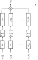
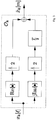
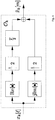
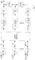
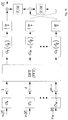
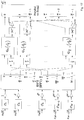
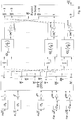
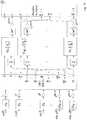
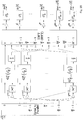
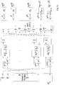
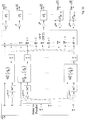
- FIG. 17 , 18 , 19 Further embodiments are depicted in Figs. 17 , 18 , 19 , for the SFB based on polyphase decompositions of type 1, 2 and 3, and in Figs. 20 , 21 , 22 , for the AFB also based on polyphase decompositions of type 1, 2 and 3.
- the structures are based on the further development of the polyphase networks from Figs. 8 for the corresponding FB and decomposition type.
- the prototype filter has a symmetric impulse response, there are pairs of polyphase components that have the same coefficients but in a reverse order. In other words they are pairs of paraconjugate filters.
- the 2 ⁇ 2 lattice or lifting structures provide four of the polyphase components. Now only M /4 such structures are necessary where each of them has 2( K + 1) multipliers for the case of lattice and 3K for the case of lifting steps.
- the second issue is that the DFT or IFDT provide M outputs, but now only M /2 inputs exist in the polyphase network. It can be demonstrated that because of the special characteristics of the signals at the input of the DFT or IDFT, the outputs actually show a big redundancy. More specifically, half of the outputs are complex conjugated versions of the other half. With this in mind, one can see that all the necessary signals are generated by half of the DFT or IDFT outputs. We just need to take the complex conjugate signal from one of the outputs of each polyphase sets. Since all coefficients of the polyphase components are real valued, this is equivalent to take the complex conjugate of the two input signals. This means that half of the outputs of the DFT or IDFT do not need to be calculated, reducing even more the total computational complexity. Similar issues exist for the AFB but in reversed order and the corresponding solutions can be seen in the structures proposed.
- an additional filter has to be included before the OQAM de-staggering for each subchannel in the AFB or after the staggering in the SFB.
- One good example is the channel equalization in multicarrier modulation schemes, where one multitap filter is included before the OQAM demapping for each subcarrier in the AFB in order to compensate for the frequency selectivity of the channel.
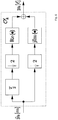
- Fig. 23 we have a new definition for the block O k ′ in the odd subchannel k that already includes the FIR equalizer.
- An equivalent scheme can be drawn for the even subchannels and a corresponding one for the SFB. We will concentrate here on the structure for odd k and only for the AFB.
- the subchannel equalizers will be multitap in general, so we can decompose the into their polyphase components also.
Landscapes
- Engineering & Computer Science (AREA)
- Computer Networks & Wireless Communication (AREA)
- Signal Processing (AREA)
- Compression, Expansion, Code Conversion, And Decoders (AREA)
- Complex Calculations (AREA)
Claims (8)
- Synthese-Filterbank, die Folgendes umfasst:- ein Transformationsmodul, das dazu konfiguriert ist, eine Vielzahl von Eingangssignalen zu empfangen, eine diskrete Fourier-Transformation oder eine inverse diskrete Fourier-Transformation durchzuführen, um die Vielzahl von Eingangssignalen zu transformieren, und eine Vielzahl von transformierten Signalen auszugeben,- eine Vielzahl von Filtermodulen, die aus einem Prototyp-Filter mit symmetrischer Impulsantwort entwickelt wurden, und die leistungskomplementäre Polyphasen-Komponenten unter Verwendung einer 2x2-Gitterstruktur oder einer 2x2-Lift-Steps-Struktur implementieren, wobei die Filtermodule mit dem Transformationsmodul gekoppelt sind, und wobei jedes Filtermodul der Vielzahl von Filtermodulen dazu konfiguriert ist, zwei transformierte Signale von dem Transformationsmodul zu empfangen, die zwei empfangenen transformierten Signale zu prozessieren, und zwei prozessierte Signale auszugeben, und- ein Parallel-Seriell-Modul, das mit der Vielzahl von Filtermodulen gekoppelt ist und dazu konfiguriert ist, die prozessierten Signale von der Vielzahl von Filtermodulen zu empfangen, die empfangenen prozessierten Signale zu kombinieren und ein kombiniertes Signal auszugeben;wobei für jedes Filtermodul der Vielzahl von Filtermodulen eines der zwei prozessierten Signale komplexkonjugiert wird, bevor es von dem Parallel-Seriell-Modul empfangen wird; und
wobei für jeden geradzahligen Zeitindex ein negatives Vorzeichen auf eines der zwei prozessierten Signale angewendet wird, bevor es von dem Parallel-Seriell-Modul empfangen wird. - Synthese-Filterbank Anspruch 1, wobei eine Anzahl der transformierten Signale, die von der Vielzahl von Filtermodulen empfangen werden, die Hälfte der Anzahl der vom Transformationsmodul empfangenen Eingangssignale beträgt.
- Synthese-Filterbank nach Anspruch 1 oder 2, wobei für jedes Filtermodul der Vielzahl von Filtermodulen eines der zwei transformierten Signale zeitlich verzögert wird, bevor es von dem jeweiligen Filtermodul empfangen wird.
- Analyse-Filterbank, die Folgendes umfasst:- ein Seriell-Parallel-Modul, das dazu konfiguriert ist, ein Eingangssignal zu empfangen und das empfangene Eingangssignal in eine Vielzahl von Ausgangssignalen aufzuteilen,- eine Vielzahl von Filtermodulen, die aus einem Prototyp-Filter mit symmetrischer Impulsantwort entwickelt wurden, und die leistungskomplementäre Polyphasen-Komponenten unter Verwendung einer 2x2-Gitterstruktur oder einer 2x2-Lift-Steps-Struktur implementieren, wobei die Filtermodule mit dem Seriell-Parallel-Modul gekoppelt sind, wobei jedes Filtermodul der Vielzahl von Filtermodulen dazu konfiguriert ist, zwei Ausgangssignale von dem Seriell-Parallel-Modul zu empfangen, die zwei empfangenen Ausgangssignale zu prozessieren und zwei prozessierte Signale auszugeben, und- ein Transformationsmodul, das mit der Vielzahl von Filtermodulen gekoppelt ist und dazu konfiguriert ist, die prozessierten Signale zu empfangen, eine diskrete Fourier-Transformation oder eine inverse diskrete Fourier-Transformation durchzuführen, um die Vielzahl der prozessierten Signale zu transformieren, und eine Vielzahl von transformierten Signalen auszugeben;wobei für jeden geradzahligen Zeitindex ein negatives Vorzeichen auf eines der zwei Ausgangssignale angewendet wird, bevor es von dem jeweiligen Filtermodul empfangen wird; und
wobei für jedes Filtermodul der Vielzahl von Filtermodulen eines der zwei Ausgangssignale komplexkonjugiert wird, bevor es von dem jeweiligen Filtermodul empfangen wird. - Analysefilterbank nach Anspruch 4, wobei für jedes Filtermodul der Vielzahl von Filtermodulen eines der zwei prozessierten Signale zeitlich verzögert wird, bevor es vom Seriell-Parallel-Modul empfangen wird.
- Filterbank, die eine Synthese-Filterbank nach einem der Ansprüche 1 bis 3 und eine Analyse-Filterbank nach einem der Ansprüche 4 bis 5 umfasst.
- Verfahren zum Betreiben einer Synthesefilterbank, umfassend- Empfangen einer Vielzahl von Eingangssignalen durch ein Transformationsmodul,- Transformieren der Vielzahl von Eingangssignalen durch das Transformationsmodul durch Ausführen einer diskreten Fourier-Transformation oder einer inversen diskreten Fourier-Transformation,- Ausgeben einer Vielzahl von transformierten Signalen durch das Transformationsmodul,- Empfangen der Vielzahl von transformierten Signalen durch eine Vielzahl von Filtermodulen, die mit dem Transformationsmodul gekoppelt sind, wobei jedes Filtermodul der Vielzahl von Filtermodulen dazu konfiguriert ist, zwei transformierte Signale vom Transformationsmodul zu empfangen, wobei die Vielzahl von Filtermodulen aus einem Prototyp-Filter mit einer symmetrischen Impulsantwort entwickelt ist, und leistungskomplementäre Polyphasen-Komponenten unter Verwendung einer 2x2-Gitterstruktur oder einer 2x2-Lifting-Steps-Struktur zu implementieren,- Prozessieren der zwei empfangenen transformierten Signale durch jedes Filtermodul der Vielzahl von Filtermodulen,- Ausgeben von zwei prozessierten Signalen durch jedes Filtermodul der Vielzahl von Filtermodulen,- Empfangen der prozessierten Signale durch ein Parallel-Seriell-Modul, das mit der Vielzahl von Filtermodulen gekoppelt ist,- Kombinieren der empfangenen prozessierten Signale durch das Parallel-Seriell-Modul und- Ausgeben eines kombinierten Signals durch das Parallel-Seriell-Modul,wobei das Verfahren ferner Folgendes umfasst: Komplex-Konjugieren eines der zwei prozessierten Signale für jedes Filtermodul der Vielzahl von Filtermodulen, bevor es vom Parallel-Seriell-Modul empfangen wird, und Anwenden eines negativen Vorzeichens auf eines der zwei prozessierten Signale für jeden geradzahligen Zeitindex, bevor es von dem Parallel-Seriell-Modul empfangen wird.
- Verfahren zum Betreiben einer Analyse-Filterbank, das Folgendes umfasst:- Empfangen eines Eingangssignals durch ein Seriell-Parallel-Modul,- Teilen des empfangenen Eingangssignals durch das Seriell-Parallel-Modul in eine Vielzahl von Ausgangssignalen,- Empfangen der Vielzahl von Ausgangssignalen durch eine Vielzahl von Filtermodulen, die mit dem Seriell-Parallel-Modul gekoppelt sind, wobei jedes Filtermodul der Vielzahl von Filtermodulen dazu konfiguriert ist, zwei Ausgangssignale vom Seriell-Parallel-Modul zu empfangen, wobei die Vielzahl von Filtermodulen aus einem Prototyp-Filter mit einer symmetrischen Impulsantwort entwickelt sind, und leistungskomplementäre Polyphasen-Komponenten unter Verwendung einer 2x2-Gitterstruktur oder einer 2x2-Lifting-Steps-Struktur zu implementieren,- Prozessieren der zwei empfangenen Ausgangssignale durch jedes Filtermodul der Vielzahl von Filtermodulen.- Ausgeben von zwei prozessierten Signalen durch jedes Filtermodul der Vielzahl von Filtermodulen,- Empfangen der prozessierten Signale durch ein Transformationsmodul, das mit der Vielzahl von Filtermodulen gekoppelt ist,- Transformieren der prozessierten Signale durch das Transformationsmodul durch Ausführen einer diskreten Fourier-Transformation oder einer inversen diskreten Fourier-Transformation, und- Ausgeben einer Vielzahl von transformierten Signalen durch das Transformationsmodul,wobei das Verfahren ferner Folgendes umfasst: Komplex-Konjugieren eines der zwei Ausgangssignale für jedes Filtermodul der Vielzahl von Filtermodulen, bevor es von dem jeweiligen Filtermodul empfangen wird, und Anwenden eines negativen Vorzeichens auf eines der zwei Ausgangssignale für jeden geradzahligen Zeitindex, bevor es von dem jeweiligen Filtermodul empfangen wird.
Priority Applications (3)
| Application Number | Priority Date | Filing Date | Title |
|---|---|---|---|
| EP16154802.9A EP3206353B1 (de) | 2016-02-09 | 2016-02-09 | Filterbänke und verfahren zum betreiben von filterbänken |
| PCT/EP2016/081541 WO2017137126A1 (en) | 2016-02-09 | 2016-12-16 | Filter banks and methods for operating filter banks |
| US16/076,957 US10594531B2 (en) | 2016-02-09 | 2016-12-16 | Filter banks and methods for operating filter banks |
Applications Claiming Priority (1)
| Application Number | Priority Date | Filing Date | Title |
|---|---|---|---|
| EP16154802.9A EP3206353B1 (de) | 2016-02-09 | 2016-02-09 | Filterbänke und verfahren zum betreiben von filterbänken |
Publications (2)
| Publication Number | Publication Date |
|---|---|
| EP3206353A1 EP3206353A1 (de) | 2017-08-16 |
| EP3206353B1 true EP3206353B1 (de) | 2020-02-05 |
Family
ID=55353034
Family Applications (1)
| Application Number | Title | Priority Date | Filing Date |
|---|---|---|---|
| EP16154802.9A Active EP3206353B1 (de) | 2016-02-09 | 2016-02-09 | Filterbänke und verfahren zum betreiben von filterbänken |
Country Status (3)
| Country | Link |
|---|---|
| US (1) | US10594531B2 (de) |
| EP (1) | EP3206353B1 (de) |
| WO (1) | WO2017137126A1 (de) |
Families Citing this family (4)
| Publication number | Priority date | Publication date | Assignee | Title |
|---|---|---|---|---|
| EP3206353B1 (de) * | 2016-02-09 | 2020-02-05 | Technische Universität München | Filterbänke und verfahren zum betreiben von filterbänken |
| CN107733830B (zh) * | 2016-08-12 | 2021-12-10 | 中兴通讯股份有限公司 | 一种多载波信号产生的方法、装置及系统 |
| EP3537678B1 (de) * | 2018-03-08 | 2022-05-04 | Institut Mines Telecom - IMT Atlantique - Bretagne - Pays de la Loire | Pseudo-schutzintervalleinführung in einen fbmc-sender |
| US11177995B2 (en) * | 2020-02-05 | 2021-11-16 | Huawei Technologies Co., Ltd. | Methods and apparatus for communicating a single carrier waveform |
Family Cites Families (67)
| Publication number | Priority date | Publication date | Assignee | Title |
|---|---|---|---|---|
| YU47270B (sh) * | 1986-10-31 | 1995-01-31 | Siemens Aktiengesellschaft Berlin I Minhen | Adaptivni korektor frekvencijskog domena za digitalne radio relejne sisteme |
| FR2765757B1 (fr) * | 1997-07-01 | 1999-09-17 | France Telecom | Procede et dispositif de modulation d'un signal multiporteuse de type ofdm/oqam, et procede et dispositif de demodulation correspondants |
| US5955992A (en) * | 1998-02-12 | 1999-09-21 | Shattil; Steve J. | Frequency-shifted feedback cavity used as a phased array antenna controller and carrier interference multiple access spread-spectrum transmitter |
| US7430257B1 (en) * | 1998-02-12 | 2008-09-30 | Lot 41 Acquisition Foundation, Llc | Multicarrier sub-layer for direct sequence channel and multiple-access coding |
| FR2799073B1 (fr) * | 1999-09-29 | 2002-01-18 | France Telecom | Procede de transmission d'un signal bfdm/oqam, procedes de modulation et de demodulation et dispositif correspondants |
| US7406261B2 (en) * | 1999-11-02 | 2008-07-29 | Lot 41 Acquisition Foundation, Llc | Unified multi-carrier framework for multiple-access technologies |
| US7272192B2 (en) * | 2000-04-14 | 2007-09-18 | Board Of Trustees Of The Leland Stanford Junior University | Time-reversal block transmit diversity system for channels with intersymbol interference and method |
| US20020150038A1 (en) * | 2000-07-10 | 2002-10-17 | Atsushi Sumasu | Multi-carrier communication device and peak power suppressing method |
| US7058004B2 (en) * | 2001-05-07 | 2006-06-06 | University Of South Florida | Communication system using orthogonal wavelet division multiplexing (OWDM) and OWDM-spread spectrum (OWSS) signaling |
| CA2390253A1 (en) * | 2001-06-11 | 2002-12-11 | Unique Broadband Systems, Inc. | Ofdm multiple sub-channel communication system |
| US7436881B2 (en) * | 2001-09-28 | 2008-10-14 | Nec Corporation | Per-bin DFE for advanced OQAM-based multi-carrier wireless data transmission systems |
| US7145972B2 (en) * | 2001-10-18 | 2006-12-05 | The Aerospace Corporation | Polyphase channelization system |
| US7206359B2 (en) * | 2002-03-29 | 2007-04-17 | Scientific Research Corporation | System and method for orthogonally multiplexed signal transmission and reception |
| DE60332893D1 (de) * | 2002-04-25 | 2010-07-22 | Imec | CDMA Empfang-übertragungstechniken für Funksysteme mit Mehrfacheingängen und Mehrfachausgängen (MIMO) |
| US7394754B2 (en) * | 2002-08-01 | 2008-07-01 | Mediatek Inc. | System and method for transmitting data in a multiple-branch transmitter-diversity orthogonal frequency-division multiplexing (OFDM) system |
| AU2003259435A1 (en) * | 2002-08-30 | 2004-03-19 | Koninklijke Philips Electronics N.V. | Frequency-domain equalization for single carrier signals |
| US7443917B2 (en) * | 2003-09-02 | 2008-10-28 | Data Jce Ltd | Method and system for transmission of information data over a communication line |
| US7324605B2 (en) * | 2004-01-12 | 2008-01-29 | Intel Corporation | High-throughput multicarrier communication systems and methods for exchanging channel state information |
| US7724835B2 (en) * | 2004-05-17 | 2010-05-25 | Qualcomm Incorporated | Space-time block coding in orthogonal frequency division communication systems |
| JP4703135B2 (ja) * | 2004-05-25 | 2011-06-15 | 株式会社エヌ・ティ・ティ・ドコモ | 送信機および送信制御方法 |
| FR2875351A1 (fr) * | 2004-09-16 | 2006-03-17 | France Telecom | Procede de traitement de donnees par passage entre domaines differents de sous-bandes |
| US7532676B2 (en) * | 2005-10-20 | 2009-05-12 | Trellis Phase Communications, Lp | Single sideband and quadrature multiplexed continuous phase modulation |
| US8406323B2 (en) * | 2006-06-14 | 2013-03-26 | Agere Systems Llc | Orthogonal frequency division multiplexing using subsymbol processing |
| FR2935856B1 (fr) * | 2008-09-10 | 2010-08-27 | Conservatoire Nat Arts | Systeme de transmission numerique multiporteuse d'un signal utilisant des bancs de filtres et le prechargement de memoires pour l'initialisation |
| JP5122529B2 (ja) * | 2009-06-23 | 2013-01-16 | 株式会社エヌ・ティ・ティ・ドコモ | 移動端末装置、無線基地局装置、無線通信方法及び無線通信システム |
| FR2951046B1 (fr) * | 2009-10-02 | 2011-10-14 | Conservatoire Nat Des Arts Et Metiers Cnam | Systemes de transmission multiporteuse de donnees numeriques et procedes de transmission utilisant de tels systemes |
| CN101741782B (zh) * | 2009-11-24 | 2012-08-15 | 东南大学 | 双层多载波超宽带无线通信方法 |
| US8581768B1 (en) * | 2011-06-27 | 2013-11-12 | Syntropy Systems, Llc | Linear to discrete quantization conversion with reduced sampling variation errors |
| FR2972091A1 (fr) * | 2011-02-28 | 2012-08-31 | France Telecom | Procede de modulation d'un signal multiporteuse de type oqam, programme d'ordinateur et modulateur correspondants |
| FR2973187B1 (fr) * | 2011-03-25 | 2013-11-15 | Commissariat Energie Atomique | Procede de traitement d'un signal multiporteuses a bancs de filtre pour la synchronisation par preambule |
| EP2719076B1 (de) * | 2011-06-10 | 2021-08-11 | Technion R&D Foundation | Empfänger, sender und verfahren für digitale multiple subbandverarbeitung |
| US10263628B2 (en) * | 2011-06-27 | 2019-04-16 | Syntropy Systems, Llc | Apparatuses and methods for converting fluctuations in periodicity of an input signal into fluctuations in amplitude of an output signal |
| CN103733585B (zh) * | 2011-06-30 | 2017-02-15 | 奥兰治 | Oqam多载波信号的时移、相移和频移估计 |
| US8731027B2 (en) * | 2011-12-05 | 2014-05-20 | Battelle Energy Alliance, Llc | Methods and apparatuses using filter banks for multi-carrier spread-spectrum signals |
| FR2985134A1 (fr) * | 2011-12-23 | 2013-06-28 | France Telecom | Procede d'emission d'au moins un signal multi-porteuse forme de symboles ofdm-oqam |
| FR2985877A1 (fr) * | 2012-01-13 | 2013-07-19 | France Telecom | Procede de modulation delivrant des symboles ofdm/oqam, procede de demodulation,dispositifs de modulation et de demodulation, et programme d'ordinateur correspondants. |
| WO2013152249A1 (en) * | 2012-04-05 | 2013-10-10 | Interdigital Patent Holdings, Inc. | Systems and methods for providing and/or using an ofdm-oqam structure |
| FR2990090A1 (fr) * | 2012-04-27 | 2013-11-01 | France Telecom | Procede de communication sans-fil avec un recepteur a antennes multiples |
| FR2990816A1 (fr) * | 2012-05-16 | 2013-11-22 | France Telecom | Procede de communication sans-fil a haut debit avec un recepteur a antennes multiples |
| FR2998436A1 (fr) * | 2012-11-19 | 2014-05-23 | France Telecom | Procede de determination d’au moins un filtre d’un banc de filtres d’un systeme de transmission ou de codage,dispositif et programme d’ordinateur correspondants. |
| CN104823402B (zh) * | 2012-11-29 | 2017-07-28 | Idac控股公司 | 一种用于在无线通信设备内执行多载波调制的方法 |
| FR3003420B1 (fr) * | 2013-03-13 | 2015-04-10 | Commissariat Energie Atomique | Recepteur fbmc utilisant une methode de synchronisation dans le domaine frequentiel |
| US8929495B2 (en) * | 2013-03-19 | 2015-01-06 | Fundacio Centre Technologic de Telecomunicacions de Catalunya | Method for equalizing filterbank multicarrier (FBMC) modulations |
| FR3006535A1 (fr) * | 2013-05-28 | 2014-12-05 | France Telecom | Procede et dispositif de modulation delivrant un signal a porteuses multiples, procede et dispositif de demodulation et programme d’ordinateur correspondants. |
| EP3039836A1 (de) * | 2013-08-29 | 2016-07-06 | Interdigital Patent Holdings, Inc. | Verfahren und vorrichtung für schneller-als-nyquist-rate-mehrträgermodulation |
| JP6148797B2 (ja) * | 2013-08-30 | 2017-06-14 | フラウンホーファー−ゲゼルシャフト・ツール・フェルデルング・デル・アンゲヴァンテン・フォルシュング・アインゲトラーゲネル・フェライン | 信号を送信する方法及び装置 |
| FR3010269B1 (fr) * | 2013-09-04 | 2015-10-02 | Commissariat Energie Atomique | Recepteur fbmc a compensation d'offset de frequence porteuse |
| PL3056022T3 (pl) * | 2013-10-07 | 2023-03-06 | Med-El Elektromedizinische Geraete Gmbh | Układ i sposób wyodrębniania cech czasowych z sygnałów podobnych do impulsów |
| FR3013928B1 (fr) * | 2013-11-28 | 2015-12-25 | Commissariat Energie Atomique | Methode d'estimation de canal pour systeme de telecommunication fbmc |
| DE102014007716A1 (de) * | 2014-05-28 | 2015-12-03 | Technische Universität München | Verfahren zur Demodulation sowie Demodulator |
| WO2016001930A1 (en) * | 2014-07-03 | 2016-01-07 | Technion Research & Development Foundation Limited | System and method for ofdm symbol receiving and processing |
| KR102291859B1 (ko) * | 2014-09-04 | 2021-08-20 | 삼성전자 주식회사 | 무선 이동 통신 시스템에서 멀티 캐리어 신호 송수신을 위한 피드백 방법 및 장치 |
| US9209936B1 (en) * | 2014-10-10 | 2015-12-08 | Huawei Technologies Co., Ltd. | Systems and methods for circular convolution |
| US10476544B2 (en) * | 2015-01-12 | 2019-11-12 | Samsung Electronics Co., Ltd. | Signal transmission and receiving method, system and apparatus based on filter bank |
| US10063401B2 (en) * | 2015-01-16 | 2018-08-28 | Samsung Electronics Co., Ltd. | Communication method and apparatus based on a filter bank multi-carrier modulation |
| CN105871766B (zh) * | 2015-01-23 | 2021-02-23 | 北京三星通信技术研究有限公司 | 干扰删除方法、干扰删除辅助方法、以及干扰删除装置 |
| CN105991257B (zh) * | 2015-01-23 | 2020-10-23 | 北京三星通信技术研究有限公司 | 基于滤波器组的信号生成、发送和接收方法及其装置 |
| JP6507047B2 (ja) * | 2015-02-10 | 2019-04-24 | 日本放送協会 | 送信装置、受信装置、及び半導体チップ |
| CN106302300B (zh) * | 2015-06-24 | 2020-07-31 | 北京三星通信技术研究有限公司 | 一种基于滤波器组多载波系统的信号发送和接收的方法及装置 |
| US10177947B2 (en) * | 2015-07-24 | 2019-01-08 | Brian G. Agee | Interference-excising diversity receiver adaptation using frame synchronous signal features and attributes |
| EP3206353B1 (de) * | 2016-02-09 | 2020-02-05 | Technische Universität München | Filterbänke und verfahren zum betreiben von filterbänken |
| FR3048839B1 (fr) * | 2016-03-14 | 2018-03-09 | Commissariat A L'energie Atomique Et Aux Energies Alternatives | Methode de synchronisation d'un systeme fbmc au moyen d'un canal rach |
| FR3050345B1 (fr) * | 2016-04-13 | 2018-04-13 | Commissariat A L'energie Atomique Et Aux Energies Alternatives | Recepteur pour systeme fbmc a codage spatio-temporel de type alamouti par blocs |
| FR3050344B1 (fr) * | 2016-04-13 | 2019-05-03 | Commissariat A L'energie Atomique Et Aux Energies Alternatives | Emetteur pour systeme fbmc a codage spatio-temporel de type alamouti par blocs |
| EP3236626B1 (de) * | 2016-04-21 | 2020-09-23 | Institut Mines Telecom / Telecom Bretagne | Filter für auf linearer modulation basierende kommunikationssysteme |
| FR3051302B1 (fr) * | 2016-05-13 | 2018-06-01 | Commissariat A L'energie Atomique Et Aux Energies Alternatives | Emetteur/ recepteur mimo-fbmc a precodage lineaire implemente dans le domaine frequentiel |
| EP3261310B1 (de) * | 2016-06-21 | 2019-08-21 | Institut Mines-Telecom / Telecom | Empfängerarchitektur für filterbank-mehrträger-kommunikationssysteme |
-
2016
- 2016-02-09 EP EP16154802.9A patent/EP3206353B1/de active Active
- 2016-12-16 US US16/076,957 patent/US10594531B2/en not_active Expired - Fee Related
- 2016-12-16 WO PCT/EP2016/081541 patent/WO2017137126A1/en not_active Ceased
Non-Patent Citations (1)
| Title |
|---|
| BALTAR LEONARDO G ET AL: "Efficient filter bank multicarrier realizations for 5G", 2015 IEEE INTERNATIONAL SYMPOSIUM ON CIRCUITS AND SYSTEMS (ISCAS), IEEE, 24 May 2015 (2015-05-24), pages 2608 - 2611, XP033183704, DOI: 10.1109/ISCAS.2015.7169220 * |
Also Published As
| Publication number | Publication date |
|---|---|
| US10594531B2 (en) | 2020-03-17 |
| US20190052499A1 (en) | 2019-02-14 |
| WO2017137126A1 (en) | 2017-08-17 |
| EP3206353A1 (de) | 2017-08-16 |
Similar Documents
| Publication | Publication Date | Title |
|---|---|---|
| AU733587B2 (en) | Method and apparatus for sub-band modulation of signals for transmission and/or storage | |
| Renfors et al. | Analysis and design of efficient and flexible fast-convolution based multirate filter banks | |
| CN101355538B (zh) | 基于滤波器组的分块传输系统频域调制系统及方法 | |
| US10594531B2 (en) | Filter banks and methods for operating filter banks | |
| CN103583024B (zh) | 用于对oqam型多载波信号进行调制的方法以及对应的调制器 | |
| KR20150035424A (ko) | 필터뱅크 기반 다중 반송파 통신 시스템에서 변조 신호 전송을 위한 송수신 방법 및 장치 | |
| US20200235973A1 (en) | Filter bank multicarrier communication system based on discrete hartley transform | |
| EP1661347B1 (de) | Verfahren und system zur übertragung von informationsdaten über eine kommunikationsleitung unter verwendung von gefilterter multiton-modulation (fmt) | |
| Diniz et al. | Design of high-resolution cosine-modulated transmultiplexers with sharp transition band | |
| JP4680459B2 (ja) | オフセット変調済み(bfdm/om)マルチキャリヤ信号を伝送するための方法 | |
| CN100571238C (zh) | 多载波系统的发射、接收装置及其发射、接收方法 | |
| Viholainen et al. | Implementation of parallel cosine and sine modulated filter banks for equalized transmultiplexer systems | |
| Mishmy et al. | Peak to average power ratio reduction in filter bank based multicarrier system | |
| Gutiérrez et al. | Systematic design of transmitter and receiver architectures for flexible filter bank multi-carrier signals | |
| Asif et al. | Performance Evaluation of DWT-FDM and FFT-OFDM for Multicarrier Communications Systems using Time Domain Zero Forcing Equalization | |
| Cruz-Roldán et al. | Joint use of DFT filter banks and modulated transmultiplexers for multicarrier communications | |
| CN107171998B (zh) | 一种异步频分多址方法 | |
| Konstantinos et al. | Receiver architectures for OFDMA systems with subband carrier allocation | |
| CN101166170B (zh) | 一种简单的基于多子带滤波器组的发射和接收装置与方法 | |
| de Barcellos et al. | A generalized oversampled structure for cosine-modulated transmultiplexers and filter banks | |
| Viholainen et al. | Alternative subband signal structures for complex modulated filter banks with perfect reconstruction | |
| Kulkarni Pranav et al. | Implementation And Analysis Of Different Types Of Transmultiplexer Structures | |
| Arya et al. | Elimination of cyclic prefix of OFDM systems using filter bank based multicarrier systems | |
| Pinchon et al. | Perfect Reconstruction Conditions and Design of Oversampled DFT-Modulated Transmultiplexers | |
| Cadena Pico | Perfect Reconstruction Filter Bank Structure Based On Interpolated FIR Filters |
Legal Events
| Date | Code | Title | Description |
|---|---|---|---|
| PUAI | Public reference made under article 153(3) epc to a published international application that has entered the european phase |
Free format text: ORIGINAL CODE: 0009012 |
|
| STAA | Information on the status of an ep patent application or granted ep patent |
Free format text: STATUS: THE APPLICATION HAS BEEN PUBLISHED |
|
| AK | Designated contracting states |
Kind code of ref document: A1 Designated state(s): AL AT BE BG CH CY CZ DE DK EE ES FI FR GB GR HR HU IE IS IT LI LT LU LV MC MK MT NL NO PL PT RO RS SE SI SK SM TR |
|
| AX | Request for extension of the european patent |
Extension state: BA ME |
|
| STAA | Information on the status of an ep patent application or granted ep patent |
Free format text: STATUS: REQUEST FOR EXAMINATION WAS MADE |
|
| 17P | Request for examination filed |
Effective date: 20180212 |
|
| RBV | Designated contracting states (corrected) |
Designated state(s): AL AT BE BG CH CY CZ DE DK EE ES FI FR GB GR HR HU IE IS IT LI LT LU LV MC MK MT NL NO PL PT RO RS SE SI SK SM TR |
|
| STAA | Information on the status of an ep patent application or granted ep patent |
Free format text: STATUS: EXAMINATION IS IN PROGRESS |
|
| 17Q | First examination report despatched |
Effective date: 20190214 |
|
| GRAP | Despatch of communication of intention to grant a patent |
Free format text: ORIGINAL CODE: EPIDOSNIGR1 |
|
| STAA | Information on the status of an ep patent application or granted ep patent |
Free format text: STATUS: GRANT OF PATENT IS INTENDED |
|
| INTG | Intention to grant announced |
Effective date: 20190822 |
|
| GRAS | Grant fee paid |
Free format text: ORIGINAL CODE: EPIDOSNIGR3 |
|
| GRAA | (expected) grant |
Free format text: ORIGINAL CODE: 0009210 |
|
| STAA | Information on the status of an ep patent application or granted ep patent |
Free format text: STATUS: THE PATENT HAS BEEN GRANTED |
|
| RIN1 | Information on inventor provided before grant (corrected) |
Inventor name: JOSEF, NOSSEK Inventor name: SLIM, ISRAA Inventor name: GOMES BALTAR, LEONARDO |
|
| AK | Designated contracting states |
Kind code of ref document: B1 Designated state(s): AL AT BE BG CH CY CZ DE DK EE ES FI FR GB GR HR HU IE IS IT LI LT LU LV MC MK MT NL NO PL PT RO RS SE SI SK SM TR |
|
| REG | Reference to a national code |
Ref country code: GB Ref legal event code: FG4D |
|
| REG | Reference to a national code |
Ref country code: AT Ref legal event code: REF Ref document number: 1230675 Country of ref document: AT Kind code of ref document: T Effective date: 20200215 |
|
| REG | Reference to a national code |
Ref country code: DE Ref legal event code: R096 Ref document number: 602016029015 Country of ref document: DE |
|
| REG | Reference to a national code |
Ref country code: IE Ref legal event code: FG4D |
|
| REG | Reference to a national code |
Ref country code: CH Ref legal event code: EP |
|
| REG | Reference to a national code |
Ref country code: NL Ref legal event code: MP Effective date: 20200205 |
|
| PG25 | Lapsed in a contracting state [announced via postgrant information from national office to epo] |
Ref country code: RS Free format text: LAPSE BECAUSE OF FAILURE TO SUBMIT A TRANSLATION OF THE DESCRIPTION OR TO PAY THE FEE WITHIN THE PRESCRIBED TIME-LIMIT Effective date: 20200205 Ref country code: FI Free format text: LAPSE BECAUSE OF FAILURE TO SUBMIT A TRANSLATION OF THE DESCRIPTION OR TO PAY THE FEE WITHIN THE PRESCRIBED TIME-LIMIT Effective date: 20200205 Ref country code: NO Free format text: LAPSE BECAUSE OF FAILURE TO SUBMIT A TRANSLATION OF THE DESCRIPTION OR TO PAY THE FEE WITHIN THE PRESCRIBED TIME-LIMIT Effective date: 20200505 Ref country code: PT Free format text: LAPSE BECAUSE OF FAILURE TO SUBMIT A TRANSLATION OF THE DESCRIPTION OR TO PAY THE FEE WITHIN THE PRESCRIBED TIME-LIMIT Effective date: 20200628 |
|
| REG | Reference to a national code |
Ref country code: LT Ref legal event code: MG4D |
|
| PG25 | Lapsed in a contracting state [announced via postgrant information from national office to epo] |
Ref country code: LV Free format text: LAPSE BECAUSE OF FAILURE TO SUBMIT A TRANSLATION OF THE DESCRIPTION OR TO PAY THE FEE WITHIN THE PRESCRIBED TIME-LIMIT Effective date: 20200205 Ref country code: SE Free format text: LAPSE BECAUSE OF FAILURE TO SUBMIT A TRANSLATION OF THE DESCRIPTION OR TO PAY THE FEE WITHIN THE PRESCRIBED TIME-LIMIT Effective date: 20200205 Ref country code: BG Free format text: LAPSE BECAUSE OF FAILURE TO SUBMIT A TRANSLATION OF THE DESCRIPTION OR TO PAY THE FEE WITHIN THE PRESCRIBED TIME-LIMIT Effective date: 20200505 Ref country code: IS Free format text: LAPSE BECAUSE OF FAILURE TO SUBMIT A TRANSLATION OF THE DESCRIPTION OR TO PAY THE FEE WITHIN THE PRESCRIBED TIME-LIMIT Effective date: 20200605 Ref country code: GR Free format text: LAPSE BECAUSE OF FAILURE TO SUBMIT A TRANSLATION OF THE DESCRIPTION OR TO PAY THE FEE WITHIN THE PRESCRIBED TIME-LIMIT Effective date: 20200506 Ref country code: HR Free format text: LAPSE BECAUSE OF FAILURE TO SUBMIT A TRANSLATION OF THE DESCRIPTION OR TO PAY THE FEE WITHIN THE PRESCRIBED TIME-LIMIT Effective date: 20200205 |
|
| PG25 | Lapsed in a contracting state [announced via postgrant information from national office to epo] |
Ref country code: NL Free format text: LAPSE BECAUSE OF FAILURE TO SUBMIT A TRANSLATION OF THE DESCRIPTION OR TO PAY THE FEE WITHIN THE PRESCRIBED TIME-LIMIT Effective date: 20200205 |
|
| REG | Reference to a national code |
Ref country code: CH Ref legal event code: PL |
|
| REG | Reference to a national code |
Ref country code: BE Ref legal event code: MM Effective date: 20200229 |
|
| PG25 | Lapsed in a contracting state [announced via postgrant information from national office to epo] |
Ref country code: DK Free format text: LAPSE BECAUSE OF FAILURE TO SUBMIT A TRANSLATION OF THE DESCRIPTION OR TO PAY THE FEE WITHIN THE PRESCRIBED TIME-LIMIT Effective date: 20200205 Ref country code: LT Free format text: LAPSE BECAUSE OF FAILURE TO SUBMIT A TRANSLATION OF THE DESCRIPTION OR TO PAY THE FEE WITHIN THE PRESCRIBED TIME-LIMIT Effective date: 20200205 Ref country code: ES Free format text: LAPSE BECAUSE OF FAILURE TO SUBMIT A TRANSLATION OF THE DESCRIPTION OR TO PAY THE FEE WITHIN THE PRESCRIBED TIME-LIMIT Effective date: 20200205 Ref country code: LU Free format text: LAPSE BECAUSE OF NON-PAYMENT OF DUE FEES Effective date: 20200209 Ref country code: SK Free format text: LAPSE BECAUSE OF FAILURE TO SUBMIT A TRANSLATION OF THE DESCRIPTION OR TO PAY THE FEE WITHIN THE PRESCRIBED TIME-LIMIT Effective date: 20200205 Ref country code: CZ Free format text: LAPSE BECAUSE OF FAILURE TO SUBMIT A TRANSLATION OF THE DESCRIPTION OR TO PAY THE FEE WITHIN THE PRESCRIBED TIME-LIMIT Effective date: 20200205 Ref country code: RO Free format text: LAPSE BECAUSE OF FAILURE TO SUBMIT A TRANSLATION OF THE DESCRIPTION OR TO PAY THE FEE WITHIN THE PRESCRIBED TIME-LIMIT Effective date: 20200205 Ref country code: SM Free format text: LAPSE BECAUSE OF FAILURE TO SUBMIT A TRANSLATION OF THE DESCRIPTION OR TO PAY THE FEE WITHIN THE PRESCRIBED TIME-LIMIT Effective date: 20200205 Ref country code: EE Free format text: LAPSE BECAUSE OF FAILURE TO SUBMIT A TRANSLATION OF THE DESCRIPTION OR TO PAY THE FEE WITHIN THE PRESCRIBED TIME-LIMIT Effective date: 20200205 |
|
| REG | Reference to a national code |
Ref country code: DE Ref legal event code: R097 Ref document number: 602016029015 Country of ref document: DE |
|
| REG | Reference to a national code |
Ref country code: AT Ref legal event code: MK05 Ref document number: 1230675 Country of ref document: AT Kind code of ref document: T Effective date: 20200205 |
|
| PG25 | Lapsed in a contracting state [announced via postgrant information from national office to epo] |
Ref country code: LI Free format text: LAPSE BECAUSE OF NON-PAYMENT OF DUE FEES Effective date: 20200229 Ref country code: MC Free format text: LAPSE BECAUSE OF FAILURE TO SUBMIT A TRANSLATION OF THE DESCRIPTION OR TO PAY THE FEE WITHIN THE PRESCRIBED TIME-LIMIT Effective date: 20200205 Ref country code: CH Free format text: LAPSE BECAUSE OF NON-PAYMENT OF DUE FEES Effective date: 20200229 |
|
| PLBE | No opposition filed within time limit |
Free format text: ORIGINAL CODE: 0009261 |
|
| STAA | Information on the status of an ep patent application or granted ep patent |
Free format text: STATUS: NO OPPOSITION FILED WITHIN TIME LIMIT |
|
| 26N | No opposition filed |
Effective date: 20201106 |
|
| PG25 | Lapsed in a contracting state [announced via postgrant information from national office to epo] |
Ref country code: IT Free format text: LAPSE BECAUSE OF FAILURE TO SUBMIT A TRANSLATION OF THE DESCRIPTION OR TO PAY THE FEE WITHIN THE PRESCRIBED TIME-LIMIT Effective date: 20200205 Ref country code: AT Free format text: LAPSE BECAUSE OF FAILURE TO SUBMIT A TRANSLATION OF THE DESCRIPTION OR TO PAY THE FEE WITHIN THE PRESCRIBED TIME-LIMIT Effective date: 20200205 Ref country code: IE Free format text: LAPSE BECAUSE OF NON-PAYMENT OF DUE FEES Effective date: 20200209 |
|
| PG25 | Lapsed in a contracting state [announced via postgrant information from national office to epo] |
Ref country code: SI Free format text: LAPSE BECAUSE OF FAILURE TO SUBMIT A TRANSLATION OF THE DESCRIPTION OR TO PAY THE FEE WITHIN THE PRESCRIBED TIME-LIMIT Effective date: 20200205 Ref country code: PL Free format text: LAPSE BECAUSE OF FAILURE TO SUBMIT A TRANSLATION OF THE DESCRIPTION OR TO PAY THE FEE WITHIN THE PRESCRIBED TIME-LIMIT Effective date: 20200205 Ref country code: BE Free format text: LAPSE BECAUSE OF NON-PAYMENT OF DUE FEES Effective date: 20200229 |
|
| PGFP | Annual fee paid to national office [announced via postgrant information from national office to epo] |
Ref country code: GB Payment date: 20211230 Year of fee payment: 7 |
|
| PGFP | Annual fee paid to national office [announced via postgrant information from national office to epo] |
Ref country code: DE Payment date: 20211230 Year of fee payment: 7 |
|
| PG25 | Lapsed in a contracting state [announced via postgrant information from national office to epo] |
Ref country code: TR Free format text: LAPSE BECAUSE OF FAILURE TO SUBMIT A TRANSLATION OF THE DESCRIPTION OR TO PAY THE FEE WITHIN THE PRESCRIBED TIME-LIMIT Effective date: 20200205 Ref country code: MT Free format text: LAPSE BECAUSE OF FAILURE TO SUBMIT A TRANSLATION OF THE DESCRIPTION OR TO PAY THE FEE WITHIN THE PRESCRIBED TIME-LIMIT Effective date: 20200205 Ref country code: CY Free format text: LAPSE BECAUSE OF FAILURE TO SUBMIT A TRANSLATION OF THE DESCRIPTION OR TO PAY THE FEE WITHIN THE PRESCRIBED TIME-LIMIT Effective date: 20200205 |
|
| PGFP | Annual fee paid to national office [announced via postgrant information from national office to epo] |
Ref country code: FR Payment date: 20220118 Year of fee payment: 7 |
|
| PG25 | Lapsed in a contracting state [announced via postgrant information from national office to epo] |
Ref country code: MK Free format text: LAPSE BECAUSE OF FAILURE TO SUBMIT A TRANSLATION OF THE DESCRIPTION OR TO PAY THE FEE WITHIN THE PRESCRIBED TIME-LIMIT Effective date: 20200205 Ref country code: AL Free format text: LAPSE BECAUSE OF FAILURE TO SUBMIT A TRANSLATION OF THE DESCRIPTION OR TO PAY THE FEE WITHIN THE PRESCRIBED TIME-LIMIT Effective date: 20200205 |
|
| REG | Reference to a national code |
Ref country code: DE Ref legal event code: R119 Ref document number: 602016029015 Country of ref document: DE |
|
| GBPC | Gb: european patent ceased through non-payment of renewal fee |
Effective date: 20230209 |
|
| PG25 | Lapsed in a contracting state [announced via postgrant information from national office to epo] |
Ref country code: GB Free format text: LAPSE BECAUSE OF NON-PAYMENT OF DUE FEES Effective date: 20230209 |
|
| PG25 | Lapsed in a contracting state [announced via postgrant information from national office to epo] |
Ref country code: GB Free format text: LAPSE BECAUSE OF NON-PAYMENT OF DUE FEES Effective date: 20230209 Ref country code: FR Free format text: LAPSE BECAUSE OF NON-PAYMENT OF DUE FEES Effective date: 20230228 Ref country code: DE Free format text: LAPSE BECAUSE OF NON-PAYMENT OF DUE FEES Effective date: 20230901 |