EP3206442A1 - Procédé et dispositif de transmission de données - Google Patents
Procédé et dispositif de transmission de données Download PDFInfo
- Publication number
- EP3206442A1 EP3206442A1 EP14905425.6A EP14905425A EP3206442A1 EP 3206442 A1 EP3206442 A1 EP 3206442A1 EP 14905425 A EP14905425 A EP 14905425A EP 3206442 A1 EP3206442 A1 EP 3206442A1
- Authority
- EP
- European Patent Office
- Prior art keywords
- moment
- candidate
- channel
- data
- cca
- Prior art date
- Legal status (The legal status is an assumption and is not a legal conclusion. Google has not performed a legal analysis and makes no representation as to the accuracy of the status listed.)
- Granted
Links
Images


Classifications
-
- H—ELECTRICITY
- H04—ELECTRIC COMMUNICATION TECHNIQUE
- H04W—WIRELESS COMMUNICATION NETWORKS
- H04W52/00—Power management, e.g. Transmission Power Control [TPC] or power classes
- H04W52/02—Power saving arrangements
- H04W52/0209—Power saving arrangements in terminal devices
- H04W52/0225—Power saving arrangements in terminal devices using monitoring of external events, e.g. the presence of a signal
- H04W52/0229—Power saving arrangements in terminal devices using monitoring of external events, e.g. the presence of a signal where the received signal is a wanted signal
-
- H—ELECTRICITY
- H04—ELECTRIC COMMUNICATION TECHNIQUE
- H04W—WIRELESS COMMUNICATION NETWORKS
- H04W52/00—Power management, e.g. Transmission Power Control [TPC] or power classes
- H04W52/02—Power saving arrangements
-
- H—ELECTRICITY
- H04—ELECTRIC COMMUNICATION TECHNIQUE
- H04W—WIRELESS COMMUNICATION NETWORKS
- H04W52/00—Power management, e.g. Transmission Power Control [TPC] or power classes
- H04W52/02—Power saving arrangements
- H04W52/0209—Power saving arrangements in terminal devices
- H04W52/0212—Power saving arrangements in terminal devices managed by the network, e.g. network or access point is leader and terminal is follower
- H04W52/0216—Power saving arrangements in terminal devices managed by the network, e.g. network or access point is leader and terminal is follower using a pre-established activity schedule, e.g. traffic indication frame
-
- H—ELECTRICITY
- H04—ELECTRIC COMMUNICATION TECHNIQUE
- H04W—WIRELESS COMMUNICATION NETWORKS
- H04W52/00—Power management, e.g. Transmission Power Control [TPC] or power classes
- H04W52/02—Power saving arrangements
- H04W52/0209—Power saving arrangements in terminal devices
- H04W52/0261—Power saving arrangements in terminal devices managing power supply demand, e.g. depending on battery level
- H04W52/0274—Power saving arrangements in terminal devices managing power supply demand, e.g. depending on battery level by switching on or off the equipment or parts thereof
-
- H—ELECTRICITY
- H04—ELECTRIC COMMUNICATION TECHNIQUE
- H04W—WIRELESS COMMUNICATION NETWORKS
- H04W74/00—Wireless channel access
- H04W74/08—Non-scheduled access, e.g. ALOHA
- H04W74/0808—Non-scheduled access, e.g. ALOHA using carrier sensing, e.g. carrier sense multiple access [CSMA]
-
- H—ELECTRICITY
- H04—ELECTRIC COMMUNICATION TECHNIQUE
- H04W—WIRELESS COMMUNICATION NETWORKS
- H04W16/00—Network planning, e.g. coverage or traffic planning tools; Network deployment, e.g. resource partitioning or cells structures
- H04W16/14—Spectrum sharing arrangements between different networks
-
- H—ELECTRICITY
- H04—ELECTRIC COMMUNICATION TECHNIQUE
- H04W—WIRELESS COMMUNICATION NETWORKS
- H04W84/00—Network topologies
- H04W84/02—Hierarchically pre-organised networks, e.g. paging networks, cellular networks, WLAN [Wireless Local Area Network] or WLL [Wireless Local Loop]
- H04W84/10—Small scale networks; Flat hierarchical networks
- H04W84/12—WLAN [Wireless Local Area Networks]
-
- Y—GENERAL TAGGING OF NEW TECHNOLOGICAL DEVELOPMENTS; GENERAL TAGGING OF CROSS-SECTIONAL TECHNOLOGIES SPANNING OVER SEVERAL SECTIONS OF THE IPC; TECHNICAL SUBJECTS COVERED BY FORMER USPC CROSS-REFERENCE ART COLLECTIONS [XRACs] AND DIGESTS
- Y02—TECHNOLOGIES OR APPLICATIONS FOR MITIGATION OR ADAPTATION AGAINST CLIMATE CHANGE
- Y02D—CLIMATE CHANGE MITIGATION TECHNOLOGIES IN INFORMATION AND COMMUNICATION TECHNOLOGIES [ICT], I.E. INFORMATION AND COMMUNICATION TECHNOLOGIES AIMING AT THE REDUCTION OF THEIR OWN ENERGY USE
- Y02D30/00—Reducing energy consumption in communication networks
- Y02D30/70—Reducing energy consumption in communication networks in wireless communication networks
Definitions
- Embodiments of the present invention relate to the field of communications technologies, and more specifically, to a data transmission method and a device.
- LBT Listen Before Talk
- Operation modes of LBT include a load based equipment (English: Load Based Equipment, “LBE” for short) operation mode and a frame based equipment (Frame Based Equipment, "FBE” for short) operation mode.
- a receiving end device needs to continuously detect a channel to acquire data. This causes relatively high power consumption of the receive end device.
- Embodiments of the present invention provide a data transmission method and a device, so that power consumption of the device can be reduced when the device receives data.
- an embodiment of the present invention provides a data transmission method, including: determining, by a first device, a candidate-moment set; determining, by the first device, a target candidate moment from the candidate-moment set; and sending, by the first device, data on a channel according to the target candidate moment.
- the determining, by the first device, a target candidate moment from the candidate-moment set includes: determining, by the first device, the target candidate moment from the candidate-moment set according to an end moment of a clear channel assessment CCA backoff process; and the sending, by the first device, data on a channel according to the target candidate moment includes: starting, by the first device, to send the data on the channel from the target candidate moment.
- the determining, by the first device, the target candidate moment from the candidate-moment set according to an end moment of a clear channel assessment CCA backoff process includes: determining, by the first device, the target candidate moment from the candidate-moment set, where the target candidate moment is equal to or later than the end moment of the CCA backoff process.
- the method further includes: starting, by the first device, to send padding data on the channel from the end moment of the CCA backoff process; and stopping, by the first device, sending the padding data on the channel from the target candidate moment, where the target candidate moment is a first candidate moment in the candidate-moment set that is later than the end moment of the CCA backoff process.
- the method further includes: starting, by the first device, to perform a CCA detection from the end moment of the CCA backoff process; and stopping, by the first device, performing the CCA detection from the target candidate moment, where the target candidate moment is a first candidate moment in the candidate-moment set at which the channel is idle and that is later than the end moment of the CCA backoff process.
- the determining, by the first device, a target candidate moment from the candidate-moment set includes: determining, by the first device, a first backoff threshold N min according to the candidate-moment set, where N min is a positive integer; determining, by the first device, an initial backoff value N from [N min , q], where q is a preset backoff threshold of the first device, and q is a positive integer greater than N min ; performing, by the first device, a clear channel assessment CCA backoff process according to the initial backoff value N; determining, by the first device, a current backoff value N c ; determining, by the first device, a second moment, where the second moment is a moment at which the current backoff value N c is equal to the first backoff threshold N min ; and determining, by the first device, the target candidate moment from the candidate-moment set, where the target candidate moment is not earlier than the second moment, the
- the sending, by the first device, data on a channel according to the target candidate moment includes: starting, by the first device, to perform a clear channel assessment CCA backoff process from the target candidate moment; and starting, by the first device, to send the data on the channel from an end moment of the CCA backoff process.
- the determining, by a first device, a candidate-moment set includes: determining, by the first device, the candidate-moment set according to a preset moment on the channel.
- the preset moment on the channel is any one of the following moments: a start moment of an orthogonal frequency division multiplexing OFDM symbol on the channel, a moment that corresponds to each 1/K of an orthogonal frequency division multiplexing symbol on the channel, a start moment of a timeslot on the channel, a start moment of a data subframe on the channel, a start moment of a data frame on the channel, or a start moment of M sampling periods on the channel, where K is a positive integer greater than 1, and M is a positive integer.
- an embodiment of the present invention provides a data transmission method, including: determining, by a second device, a candidate-moment set; determining, by the second device, each candidate moment in the candidate-moment set; and receiving, by the second device, data on a channel according to each candidate moment.
- the receiving, by the second device, data on a channel according to each candidate moment includes: performing, by the second device, a channel detection on the channel at each candidate moment, so as to receive the data on the channel.
- the receiving, by the second device, data on a channel according to each candidate moment includes: determining, by the second device, an end moment of each clear channel assessment CCA detection according to each candidate moment; and performing, by the second device, a channel detection on the channel at the end moment of each CCA detection, so as to receive the data on the channel.
- the determining, by a second device, a candidate-moment set includes: determining, by the second device, the candidate-moment set according to a preset moment on the channel.
- the preset moment on the channel is any one of the following moments: a start moment of an orthogonal frequency division multiplexing OFDM symbol on the channel, a moment that corresponds to each 1/K of an OFDM symbol on the channel, a start moment of a timeslot on the channel, a start moment of a data subframe on the channel, a start moment of a data frame on the channel, or a start moment of M sampling periods on the channel, where K is a positive integer greater than 1, and M is a positive integer.
- an embodiment of the present invention provides a first device, where the first device includes a first determining unit, a second determining unit, and a sending unit, where the first determining unit is configured to determine a candidate-moment set; the second determining unit is configured to determine a target candidate moment from the candidate-moment set determined by the first determining unit; and the sending unit is configured to send data on a channel according to the target candidate moment determined by the second determining unit.
- the second determining unit is specifically configured to determine the target candidate moment from the candidate-moment set according to an end moment of a clear channel assessment CCA backoff process; and the sending unit is specifically configured to start to send the data on the channel from the target candidate moment.
- the second determining unit is specifically configured to determine the target candidate moment from the candidate-moment set, where the target candidate moment is equal to or later than the end moment of the CCA backoff process.
- the sending unit is further configured to: if the target candidate moment is a candidate moment in the candidate-moment set that is later than the end moment of the CCA backoff process, start to send padding data on the channel from the end moment of the CCA backoff process, and stop sending the padding data on the channel from the target candidate moment, where the target candidate moment is a first candidate moment in the candidate-moment set that is later than the end moment of the CCA backoff process.
- the second determining unit is further configured to: if the target candidate moment is a candidate moment in the candidate-moment set that is later than the end moment of the CCA backoff process, start to perform a CCA detection from the end moment of the CCA backoff process, and stop performing the CCA detection from the target candidate moment, where the target candidate moment is a first candidate moment in the candidate-moment set at which the channel is idle and that is later than the end moment of the CCA backoff process.
- the second determining unit is specifically configured to: determine a first backoff threshold N min according to the candidate-moment set, where N min is a positive integer; determine an initial backoff value N from [N min , q], where q is a preset backoff threshold of the first device, and q is a positive integer greater than N min ; perform a clear channel assessment CCA backoff process according to the initial backoff value N; determine a current backoff value N c ; determine a second moment, where the second moment is a moment at which the current backoff value N c is equal to the first backoff threshold N min ; and determine the target candidate moment from the candidate-moment set, where the target candidate moment is not earlier than the second moment, the target candidate moment is earlier than a third moment, and the third moment is a moment at which the current backoff value N c is equal to 0; and the sending unit is specifically configured to start to send the data on the channel from the target candidate candidate
- the second determining unit is further configured to start to perform a clear channel assessment CCA backoff process from the target candidate moment; and the sending unit is specifically configured to start to send the data on the channel from an end moment of the CCA backoff process.
- the first determining unit is specifically configured to determine the candidate-moment set according to a preset moment on the channel.
- an embodiment of the present invention provides a second device, where the second device includes a first determining unit, a second determining unit, and a receiving unit, where the first determining unit is configured to determine a candidate-moment set; the second determining unit is configured to determine each candidate moment in the candidate-moment set determined by the first determining unit; and the receiving unit is configured to receive data on a channel according to each candidate moment determined by the second determining unit.
- the receiving unit is specifically configured to perform a channel detection on the channel at each candidate moment, so as to receive the data on the channel.
- the second determining unit is further configured to determine an end moment of each clear channel assessment CCA detection according to each candidate moment; and the receiving unit is specifically configured to perform a channel detection on the channel at the end moment of each CCA detection, so as to receive the data on the channel.
- the first determining unit is specifically configured to determine the candidate-moment set according to a preset moment on the channel.
- an embodiment of the present invention provides a first device, where the first device includes a processor and a transmitter, where the processor is configured to determine a candidate-moment set; the processor is further configured to determine a target candidate moment from the candidate-moment set determined by the processor; and the transmitter is configured to send data on a channel according to the target candidate moment determined by the processor.
- the processor is specifically configured to determine the target candidate moment from the candidate-moment set according to an end moment of a clear channel assessment CCA backoff process; and the transmitter is specifically configured to start to send the data on the channel from the target candidate moment.
- the processor is specifically configured to determine the target candidate moment from the candidate-moment set, where the target candidate moment is equal to or later than the end moment of the CCA backoff process.
- the transmitter is further configured to: if the target candidate moment is a candidate moment in the candidate-moment set that is later than the end moment of the CCA backoff process, start to send padding data on the channel from the end moment of the CCA backoff process, and stop sending the padding data on the channel from the target candidate moment, where the target candidate moment is a first candidate moment in the candidate-moment set that is later than the end moment of the CCA backoff process.
- the processor is further configured to: if the target candidate moment is a candidate moment in the candidate-moment set that is later than the end moment of the CCA backoff process, start to perform a CCA detection from the end moment of the CCA backoff process, and stop performing the CCA detection from the target candidate moment, where the target candidate moment is a first candidate moment in the candidate-moment set at which the channel is idle and that is later than the end moment of the CCA backoff process.
- the processor is specifically configured to: determine a first backoff threshold N min according to the candidate-moment set, where N min is a positive integer; determine an initial backoff value N from [N min , q], where q is a preset backoff threshold of the first device, and q is a positive integer greater than N min ; perform a clear channel assessment CCA backoff process according to the initial backoff value N; determine a current backoff value N c ; determine a second moment, where the second moment is a moment at which the current backoff value N c is equal to the first backoff threshold N min ; and determine the target candidate moment from the candidate-moment set, where the target candidate moment is not earlier than the second moment, the target candidate moment is earlier than a third moment, and the third moment is a moment at which the current backoff value N c is equal to 0; and the transmitter is specifically configured to start to send the data on the channel from the target candidate moment.
- the processor is further configured to start to perform a clear channel assessment CCA backoff process from the target candidate moment; and the transmitter is specifically configured to start to send the data on the channel from an end moment of the CCA backoff process.
- the processor is specifically configured to determine the candidate-moment set according to a preset moment on the channel.
- an embodiment of the present invention provides a second device, where the second device includes a processor and a receiver, where the processor is configured to determine a candidate-moment set; the processor is further configured to determine each candidate moment in the candidate-moment set determined by the processor; and the receiver is configured to receive data on a channel according to each candidate moment determined by the processor.
- the receiver is specifically configured to perform a channel detection on the channel at each candidate moment, so as to receive the data on the channel.
- the processor is further configured to determine an end moment of each clear channel assessment CCA detection according to each candidate moment; and the receiver is specifically configured to perform a channel detection on the channel at the end moment of each CCA detection, so as to receive the data on the channel.
- the processor is specifically configured to determine the candidate-moment set according to a preset moment on the channel.
- a moment at which a first device sends data is determined according to a candidate moment in a candidate-moment set.
- a corresponding second device that receives the data may also determine, according to the candidate moment in the candidate-moment set, a moment at which the data can be received. That is, the second device may perform a channel detection only at a moment at which the data can be sent and that is specified in a system, and does not need to continually perform the channel detection at other moments. Therefore, the foregoing technical solutions can reduce power consumption of the second device during the channel detection.
- Devices involved in the embodiments of the present invention are all devices in an LAA-LTE system. More specifically, the devices involved in the embodiments of the present invention are all devices that operate in an LBE operation mode.
- the devices involved in the embodiments of the present invention may be user equipment or network side devices.
- the user equipment may also be referred to as a mobile terminal, for example, a mobile phone (or referred to as a "cellular" phone) or a computer with a mobile terminal.
- the user equipment may be a portable, pocket-sized, handheld, computer built-in, or in-vehicle mobile apparatus, and is not limited in the present invention.
- the network side device may be a base station or an access point (English: Access Point, "AP" for short), and is not limited in the present invention.
- first, second, and third in a first device, a second device, and a third device in the embodiments of the present invention are only intended for distinguishing the devices, but not for limiting the devices.
- the current backoff value N c that is determined after the device performs the CCA detection is 0, it may be considered that the result of the CCA backoff satisfies the backoff condition. If the current backoff value N c that is determined after the device performs the CCA detection is a positive integer greater than 0, it may be considered that the result of the CCA backoff does not satisfy the backoff condition.
- the channel or channel resource mentioned in the embodiments of the present invention may be a channel resource on an unlicensed spectrum, or may be a channel resource on a licensed spectrum.
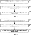
- FIG. 1 is a schematic flowchart of a data transmission method according to an embodiment of the present invention. The method shown in FIG. 1 is performed by a first device, and the first device may be a device in an LAA-LTE system.
- a moment at which a first device sends data is determined according to a candidate moment in a candidate-moment set.
- a corresponding second device that receives the data may also determine, according to the candidate moment in the candidate-moment set, a moment at which the data can be received. That is, the second device may perform a channel detection only at a moment at which the data can be sent and that is specified in a system, and does not need to continually perform the channel detection at other moments. Therefore, the method shown in FIG. 1 can reduce power consumption of the second device during the channel detection.
- the first device may determine the candidate-moment set in multiple manners, and this is not limited in the present invention.
- the candidate-moment set may be preconfigured and stored in the first device.
- the candidate-moment set may be preconfigured and stored in the first device.
- the first device may send the candidate-moment set to another device.
- the candidate-moment set may be determined by the first device.
- the first device may send the candidate-moment set to another device.
- the candidate-moment set may be sent by a third device to the first device and a second device.
- the second device is a device that receives the data sent by the first device.
- the candidate-moment set is determined by the first device according to feedback information sent by the second device.
- the second device is a device that receives the data sent by the first device.
- the candidate-moment set may be flexibly configured.
- the candidate-moment set may be periodical or non-periodical.
- the candidate-moment set may be expressed by using a group of preset moments, or the candidate-moment set may be expressed by using a formula.
- the determining, by the first device, a target candidate moment from the candidate-moment set includes: determining, by the first device, the target candidate moment from the candidate-moment set according to an end moment of a CCA backoff process.
- the sending, by the first device, data to a second device according to the target candidate moment includes: starting, by the first device, to send the data on the channel from the target candidate moment.
- the determining, by the first device, the target candidate moment from the candidate-moment set according to an end moment of a CCA backoff process includes: determining, by the first device, the target candidate moment from the candidate-moment set, where the target candidate moment is equal to or later than the end moment of the CCA backoff process.
- the target candidate moment may be equal to the end moment of the clear channel assessment backoff process. If the candidate-moment set does not include the end moment of the clear channel assessment backoff process, the target candidate moment may be a candidate moment in the candidate-moment set that is later than the end moment of the clear channel assessment backoff process.
- the method further includes: starting, by the first device, to send padding (English: padding) data on the channel from the end moment of the clear channel assessment backoff process; and stopping, by the first device, sending the padding data on the channel from the target candidate moment.
- the target candidate moment is a first candidate moment in the candidate-moment set that is later than the end moment of the clear channel assessment backoff process. In this way, by sending the padding data, the first device may prevent a channel resource from being occupied by another device.
- the method further includes: starting, by the first device, to perform a CCA detection from the end moment of the CCA backoff process; and stopping, by the first device, performing the CCA detection from the target candidate moment, where the target candidate moment is a first candidate moment in the candidate-moment set at which the channel is idle and that is later than the end moment of the CCA backoff process.
- the target candidate moment is a candidate moment later than the end moment of the CCA backoff process, and the channel is idle at the candidate moment.
- the determining, by the first device, a target candidate moment from the candidate-moment set includes: determining, by the first device, a first backoff threshold N min according to the candidate-moment set, where N min is a positive integer; determining, by the first device, an initial backoff value N from [N min , q], where q is a preset backoff threshold of the first device, and q is a positive integer greater than N min ; performing, by the first device, a CCA backoff process according to the initial backoff value N; determining, by the first device, a current backoff value N c ; determining, by the first device, a second moment, where the second moment is a moment at which the current backoff value N c is equal to the first backoff threshold N min ; and determining, by the first device, the target candidate moment from the candidate-moment set, where the target candidate moment is not earlier than the second moment, the target candidate moment is earlier than a third moment, and the third moment
- the sending, by the first device, data on a channel according to the target candidate moment includes: starting, by the first device, to send the data on the channel from the target candidate moment.
- the target candidate moment may be a first candidate moment in the candidate-moment set that is later than the second moment.
- the sending, by the first device, data to a second device on a channel according to the target candidate moment includes: starting, by the first device, to perform a CCA backoff from the target candidate moment; and starting, by the first device, to send the data on the channel from an end moment of the CCA backoff.
- the determining, by a first device, a candidate-moment set includes: determining, by the first device, the candidate-moment set according to a preset moment on the channel.
- the preset moment on the channel is any one of the following moments: a start moment of an orthogonal frequency division multiplexing (English: Orthogonal Frequency Division Multiplexing, "OFDM" for short) symbol on the channel, a moment that corresponds to each 1/K of an OFDM symbol on the channel, a start moment of a timeslot on the channel, a start moment of a data subframe on the channel, a start moment of a data frame on the channel, or a start moment of M sampling periods on the channel, where K is a positive integer greater than 1, and M is a positive integer.
- OFDM Orthogonal Frequency Division Multiplexing
- the first candidate moment in the candidate-moment set is a start moment of a data frame whose system frame number is n, where n is a positive integer or n may be equal to 0.
- Other candidate moments in the candidate-moment set are start moments of the M sampling periods on the channel.
- M may be equal to 560 or 624.
- a value of K may be 2 or 3. That is, each 1/2 or each 1/3 of the OFDM symbol on the channel is used as a candidate moment in the candidate-moment set.
- the candidate moments in the candidate-moment set may be multiple moments of a subframe on the channel.
- Candidate moments in one subframe and a quantity of the candidate moments in one subframe may be related to sampling periods. For example, 30 candidate moments in 576 sampling periods and 24 candidate moments in 560 sampling periods may be preset in one subframe.
- the 30 candidate moments in the 576 sampling periods mean that totally 30 candidate moments are set in the subframe, and each candidate moment is a start moment of one of the 576 sampling periods.
- the 24 candidate moments in the 560 sampling periods mean that totally 24 candidate moments are set in the subframe, and each candidate moment is a start moment of one of the 560 sampling periods. That is, the subframe may totally include 54 candidate moments.
- 30 candidate moments of the 54 candidate moments are start moments of the 576 sampling periods, and 24 candidate moments of the 54 candidate moments are start moments of the 560 sampling periods.
- An arrangement order of the 54 candidate moments is not limited.
- 9 candidate moments in 640 sampling periods and 40 candidate moments in 624 sampling periods may be preset in one subframe. In this case, the subframe totally includes 49 candidate moments. 9 candidate moments of the 49 candidate moments are start moments of the 640 sampling periods, and 40 candidate moments of the 49 candidate moments are start moments of the 624 sampling periods.
- FIG. 2 is a schematic flowchart of a data transmission method according to an embodiment of the present invention.
- the method shown in FIG. 2 is performed by a second device, and the second device may be a device in an LAA-LTE system.
- the second device may determine, according to each candidate moment in the candidate-moment set, the moment at which the data can be received. That is, the second device may perform a channel detection only at a moment at which the data can be sent and that is specified in a system, and does not need to continually perform the channel detection at other moments. Therefore, power consumption of the second device during the channel detection is reduced.
- the data received by the second device may be sent by the first device shown in FIG. 1 .
- the second device may obtain the candidate-moment set in multiple manners, and this is not limited in the present invention.
- the candidate-moment set may be preconfigured and stored in the first device and the second device.
- the candidate-moment set may be preconfigured and stored in the first device.
- the second device may receive the candidate-moment set sent by the first device.
- the candidate-moment set may be determined by the first device.
- the first device may send a sending moment sequence to the second device.
- the second device may determine feedback information used to indicate the candidate-moment set, and send the feedback information to the first device that sends the data.
- the candidate-moment set may be flexibly configured.
- the candidate-moment set may be periodical or non-periodical.
- the candidate-moment set may be expressed by using a group of preset moments, or the candidate-moment set may be expressed by using a formula. This is not limited in present invention.
- the receiving, by the second device, data on a channel according to each candidate moment includes: performing, by the second device, a channel detection on the channel at each candidate moment, so as to receive the data on the channel.
- the receiving, by the second device, data on a channel according to each candidate moment includes: determining, by the second device, an end moment of each CCA detection according to each candidate moment; and performing, by the second device, a channel detection on the channel at the end moment of each CCA detection, so as to receive the data on the channel.
- the determining, by a second device, a candidate-moment set includes: determining, by the second device, the candidate-moment set according to a preset moment on the channel.
- the determining, by a second device, a candidate-moment set includes: determining, by the second device, the candidate-moment set according to a preset moment on the channel.
- the preset moment on the channel is any one of the following moments: a start moment of an orthogonal frequency division multiplexing (English: Orthogonal Frequency Division Multiplexing, "OFDM" for short) symbol on the channel, a moment that corresponds to each 1/K of an OFDM symbol on the channel, a start moment of a timeslot on the channel, a start moment of a data subframe on the channel, a start moment of a data frame on the channel, or a start moment of M sampling periods on the channel, where K is a positive integer greater than 1, and M is a positive integer.
- OFDM Orthogonal Frequency Division Multiplexing
- the first candidate moment in the candidate-moment set is a start moment of a data frame whose system frame number is n, where n is a positive integer or n may be equal to 0.
- Other candidate moments in the candidate-moment set are start moments of the M sampling periods on the channel.
- M may be equal to 560 or 624.
- a value of K may be 2 or 3. That is, each 1/2 or each 1/3 of the OFDM symbol on the channel is used as a candidate moment in the candidate-moment set.
- the candidate moments in the candidate-moment set may be multiple moments of a subframe on the channel.
- Candidate moments in one subframe and a quantity of the candidate moments in one subframe may be related to sampling periods. For example, 30 candidate moments in 576 sampling periods and 24 candidate moments in 560 sampling periods may be preset in one subframe.
- the 30 candidate moments in the 576 sampling periods mean that totally 30 candidate moments are set in the subframe, and each candidate moment is a start moment of one of the 576 sampling periods.
- the 24 candidate moments in the 560 sampling periods mean that totally 24 candidate moments are set in the subframe, and each candidate moment is a start moment of one of the 560 sampling periods. That is, the subframe may totally include 54 candidate moments.
- 30 candidate moments of the 54 candidate moments are start moments of the 576 sampling periods, and 24 candidate moments of the 54 candidate moments are start moments of the 560 sampling periods.
- An arrangement order of the 54 candidate moments is not limited.
- 9 candidate moments in 640 sampling periods and 40 candidate moments in 624 sampling periods may be preset in one subframe. In this case, the subframe totally includes 49 candidate moments. 9 candidate moments of the 49 candidate moments are start moments of the 640 sampling periods, and 40 candidate moments of the 49 candidate moments are start moments of the 624 sampling periods.
- FIG. 3 is a schematic flowchart of a data transmission method according to another embodiment of the present invention.
- a first device performs a CCA backoff and determines an end moment of a CCA backoff process, where the end moment of the CCA backoff process is a moment at which a result of the CCA backoff satisfies a backoff condition.
- a first device performs a CCA backoff includes: The first device determines, according to a CCA, that a channel is occupied. The first device determines an initial backoff value. The first device determines a result of the CCA backoff and determines, according to the result of the CCA backoff, whether a backoff condition is satisfied. If the first device determines, according to the result of the CCA backoff, that the backoff condition is satisfied, the first device completes the CCA backoff. If the first device determines, according to the result of the CCA backoff, that the backoff condition is not satisfied, the first device continues to perform the CCA backoff.
- the first device determines whether the candidate-moment set includes a moment the same as the end moment of the CCA backoff process.
- the first device may determine that the end moment of the CCA backoff process is a target candidate moment. If the first device determines that the candidate-moment set does not include a moment the same as the end moment of the CCA backoff process, the first device may select a target candidate moment from a candidate moment in the candidate-moment set that is later than the end moment of the CCA backoff process.
- the target candidate moment may be a candidate moment later than the end moment of the CCA backoff process.
- the method further includes step 303 and step 304.
- the first device starts, from the end moment of the CCA backoff process, to send padding (English: padding) data by using a channel.
- the first device stops sending the padding data from a target candidate moment, where the target candidate moment is a first candidate moment in the candidate-moment set that is later than the end moment of the CCA backoff process.
- the first device occupies the channel from the end moment of the CCA backoff process. Therefore, the first device may determine that the target candidate moment is the first candidate moment later than the end moment of the clear channel assessment backoff process.
- step 303 and step 304 the first device may occupy the channel, to prevent another device from preempting the channel.
- the method may further include step 305 and step 306.
- the first device starts to perform a CCA detection from the end moment of the CCA backoff process.
- the first device stops performing the CCA detection from the target candidate moment, where the target candidate moment is a first candidate moment in the candidate-moment set at which the channel is idle and that is later than the end moment of the CCA backoff process.
- Step 305 and step 306 may be considered as that after a current backoff value is equal to 0, the first device continues to perform a CCA detection until the first candidate moment at which the channel is idle and that is later than the end moment of the CCA backoff process. That is, if the first device determines that the channel is occupied at the first candidate moment later than the end moment of the CCA backoff process, the first device continues to perform a CCA detection until the first candidate moment at which the channel is idle and that is later than the end moment of the CCA backoff process.
- the first device starts to send data to a second device on the channel from the target candidate moment.
- the second device determines each candidate moment in the candidate-moment set.
- the second device performs a channel detection on the channel at each candidate moment, so as to receive the data on the channel.
- step 308 and step 309 may be performed before or after any one of step 301 to step 307.
- a moment at which a first device sends data is a candidate moment in a preset candidate-moment set.
- a second device also starts to perform a channel detection only at a candidate moment in the candidate-moment set, so as to receive the data.
- the second device can accurately receive the data sent by the first device, without needing to continually perform the channel detection.
- power consumption of the second device during receiving of the data is greatly reduced.
- FIG. 4 is a schematic diagram of a data transmission method according to another embodiment of the present invention. Specifically, a sequence diagram shown in FIG. 4 is a schematic diagram according to an embodiment of the data transmission method shown in FIG. 3 .
- Moments t1, t2, t5, and t6 shown in FIG. 4 are separately four continual candidate moments in a candidate-moment set.
- the four moments t1, t2, t5, and t6 are moments at which data may be sent. Therefore, a second device may perform a channel detection at the four moments, so as to prepare to receive the data.
- a first device starts to perform a CCA backoff from the moment t3.
- a moment t4 is a moment at which a result of the CCA backoff of the first device satisfies a backoff condition.
- the moment t4 is not a candidate moment.
- the first device starts, from the moment t4, to send padding data by using a channel.
- the moment t5 is a candidate moment in the candidate-moment set. Therefore, from the moment t5, the first device stops sending the padding data and starts to send the data on the channel.
- FIG. 5 is a schematic diagram of a data transmission method according to another embodiment of the present invention. Specifically, a sequence diagram shown in FIG. 5 is a schematic diagram according to another embodiment of the data transmission method shown in FIG. 3 .
- Moments t1, t2, t5, and t6 shown in FIG. 5 are separately four continual candidate moments in a candidate-moment set.
- the four moments t1, t2, t5, and t6 are moments at which data may be sent. Therefore, a second device may perform a channel detection at the four moments, so as to prepare to receive the data.
- a first device starts to perform a CCA backoff from the moment t3.
- a moment t4 is a moment at which a result of the CCA backoff of the first device satisfies a backoff condition.
- the moment t4 is not a candidate moment. In this case, the first device starts to perform a CCA detection from the moment t4.
- the first device may start, from the moment t5, to send the data by using the channel. It may be understood that, the CCA detection shown in FIG. 5 refers to all CCA detections from the moment t4 to the moment t5.
- FIG. 6 is a schematic flowchart of a data transmission method according to another embodiment of the present invention.
- step 606 and step 607 may be performed before or after any one of step 601 to step 605.
- a moment at which a first device sends data is a candidate moment in a preset candidate-moment set.
- a second device also starts to perform a channel detection only at a candidate moment in the candidate-moment set, so as to receive the data.
- the second device can accurately receive the data sent by the first device, without needing to continually perform the channel detection.
- power consumption of the second device during receiving of the data is greatly reduced.
- FIG. 7 is a schematic diagram of a data transmission method according to another embodiment of the present invention. Specifically, a sequence diagram shown in FIG. 7 is a schematic diagram according to the data transmission method shown in FIG. 6 .
- Moments t1, t3, and t5 shown in FIG. 7 are three continual candidate moments in a candidate-moment set.
- the three moments t1, t3, and t5 are moments at which data may be sent. Therefore, a second device may perform a channel detection at the three moments, so as to prepare to receive the data.
- a moment t2 is a moment at which a first device starts to perform a CCA backoff.
- a current backoff value N c of the first device is equal to an initial backoff value N.
- a moment t4 is a moment at which the current backoff value N c is equal to N min .
- the first device may start, from a first candidate moment after the moment t4, to send the data by using a channel. In addition, the first device starts to send the data before a result of the CCA backoff becomes that N c is equal to 0.
- FIG. 8 is a schematic flowchart of a data transmission method according to another embodiment of the present invention.
- a moment at which the CCA backoff starts to be performed is determined according to the preset candidate-moment set, and duration of each CCA detection is known. Therefore, the end moment of each CCA detection is also known.
- a start moment at which the first device sends the data is the end moment of the CCA detection. Therefore, the second device may start to listen to a channel resource at the end moment of each CCA detection. In this way, the second device does not need to continually perform a channel detection during a CCA detection. Therefore, power consumption of the second device is reduced.
- FIG. 9 is a schematic diagram of a data transmission method according to another embodiment of the present invention. Specifically, a sequence diagram shown in FIG. 9 is a schematic diagram according to the data transmission method shown in FIG. 8 .
- Moments t1, t3, and t5 shown in FIG. 9 are three continual candidate moments in a candidate-moment set.
- a second device may determine an end moment of each CCA detection according to each candidate moment, and perform a channel detection at the end moment of each CCA detection, so as to receive data.
- a channel resource is occupied.
- the channel resource becomes idle from the moment t2.
- a first device starts to perform a CCA backoff from a first candidate moment (that is, the moment t3) after the moment t2.
- a result of the CCA backoff satisfies a backoff condition.
- the first device starts to send the data from the moment t4.
- FIG. 10 is a structural block diagram of a first device according to an embodiment of the present invention. As shown in FIG. 10 , the first device 1000 includes a first determining unit 1001, a second determining unit 1002, and a sending unit 1003.
- the first determining unit 1001 is configured to determine a candidate-moment set.
- the second determining unit 1002 is configured to determine a target candidate moment from the candidate-moment set determined by the first determining unit 1001.
- the sending unit 1003 is configured to send data on a channel according to the target candidate moment determined by the second determining unit 1002.
- a moment at which the first device 1000 shown in FIG. 10 sends data is determined according to a candidate moment in a candidate-moment set.
- a corresponding device that receives the data may also determine, according to the candidate moment in the candidate-moment set, a moment at which the data can be received. That is, the device that receives the data may perform a channel detection only at a moment at which the data can be sent and that is specified in a system, and does not need to continually perform the channel detection at other moments. According to the first device 1000, power consumption of the device, which receives the data, during the channel detection can be reduced.
- the second determining unit 1002 is specifically configured to determine the target candidate moment from the candidate-moment set according to an end moment of a clear channel assessment CCA backoff process.
- the sending unit 1003 is specifically configured to start to send the data on the channel from the target candidate moment.
- the second determining unit 1002 is specifically configured to determine the target candidate moment from the candidate-moment set, where the target candidate moment is equal to or later than the end moment of the CCA backoff process.
- the sending unit 1003 is further configured to: if the target candidate moment is a candidate moment in the candidate-moment set that is later than the end moment of the CCA backoff process, start to send padding data on the channel from the end moment of the CCA backoff process, and stop sending the padding data on the channel from the target candidate moment, where the target candidate moment is a first candidate moment in the candidate-moment set that is later than the end moment of the CCA backoff process.
- the second determining unit 1002 is further configured to: if the target candidate moment is a candidate moment in the candidate-moment set that is later than the end moment of the CCA backoff process, start to perform a CCA detection from the end moment of the CCA backoff process, and stop performing the CCA detection from the target candidate moment, where the target candidate moment is a first candidate moment in the candidate-moment set at which the channel is idle and that is later than the end moment of the CCA backoff process.
- the second determining unit 1002 is specifically configured to: determine a first backoff threshold N min according to the candidate-moment set, where N min is a positive integer; determine an initial backoff value N from [N min , q], where q is a preset backoff threshold of the first device, and q is a positive integer greater than N min ; perform a clear channel assessment CCA backoff process according to the initial backoff value N; determine a current backoff value N c ; determine a second moment, where the second moment is a moment at which the current backoff value N c is equal to the first backoff threshold N min ; and determine the target candidate moment from the candidate-moment set, where the target candidate moment is not earlier than the second moment, the target candidate moment is earlier than a third moment, and the third moment is a moment at which the current backoff value N c is equal to 0.
- the sending unit 1003 is specifically configured to start to send the data on the channel from the target candidate moment.
- the second determining unit 1002 is further configured to start to perform a clear channel assessment CCA backoff process from the target candidate moment.
- the sending unit 1003 is specifically configured to start to send the data on the channel from an end moment of the CCA backoff process.
- the first determining unit 1001 is specifically configured to determine the candidate-moment set according to a preset moment on the channel.
- the preset moment on the channel is any one of the following moments: a start moment of an orthogonal frequency division multiplexing (English: Orthogonal Frequency Division Multiplexing, "OFDM" for short) symbol on the channel, a moment that corresponds to each 1/K of an OFDM symbol on the channel, a start moment of a timeslot on the channel, a start moment of a data subframe on the channel, a start moment of a data frame on the channel, or a start moment of M sampling periods on the channel, where K is a positive integer greater than 1, and M is a positive integer.
- OFDM Orthogonal Frequency Division Multiplexing
- the first candidate moment in the candidate-moment set is a start moment of a data frame whose system frame number is n, where n is a positive integer or n may be equal to 0.
- Other candidate moments in the candidate-moment set are start moments of the M sampling periods on the channel.
- M may be equal to 560 or 624.
- a value of K may be 2 or 3. That is, each 1/2 or each 1/3 of the OFDM symbol on the channel is used as a candidate moment in the candidate-moment set.
- the candidate moments in the candidate-moment set may be multiple moments of a subframe on the channel.
- Candidate moments in one subframe and a quantity of the candidate moments in one subframe may be related to sampling periods. For example, 30 candidate moments in 576 sampling periods and 24 candidate moments in 560 sampling periods may be preset in one subframe.
- the 30 candidate moments in the 576 sampling periods mean that totally 30 candidate moments are set in the subframe, and each candidate moment is a start moment of one of the 576 sampling periods.
- the 24 candidate moments in the 560 sampling periods mean that totally 24 candidate moments are set in the subframe, and each candidate moment is a start moment of one of the 560 sampling periods. That is, the subframe may totally include 54 candidate moments.
- 30 candidate moments of the 54 candidate moments are start moments of the 576 sampling periods, and 24 candidate moments of the 54 candidate moments are start moments of the 560 sampling periods.
- An arrangement order of the 54 candidate moments is not limited.
- 9 candidate moments in 640 sampling periods and 40 candidate moments in 624 sampling periods may be preset in one subframe. In this case, the subframe totally includes 49 candidate moments. 9 candidate moments of the 49 candidate moments are start moments of the 640 sampling periods, and 40 candidate moments of the 49 candidate moments are start moments of the 624 sampling periods.
- FIG. 11 is a structural block diagram of a second device according to an embodiment of the present invention. As shown in FIG. 11 , the second device 1100 includes a first determining unit 1101, a second determining unit 1102, and a receiving unit 1103.
- the first determining unit 1101 is configured to determine a candidate-moment set.
- the second determining unit 1102 is configured to determine each candidate moment in the candidate-moment set determined by the first determining unit 1101.
- the receiving unit 1103 is configured to receive data on a channel according to each candidate moment determined by the second determining unit 1102.
- the second device 1100 shown in FIG. 11 may determine, according to each candidate moment in the candidate-moment set, the moment at which the data can be received. That is, the second device 1100 may perform a channel detection only at a moment at which the data can be sent and that is specified in a system, and does not need to continually perform the channel detection at other moments. Therefore, power consumption of the second device 1100 during the channel detection is reduced.
- the receiving unit 1103 is specifically configured to perform a channel detection on the channel at each candidate moment, so as to receive the data on the channel.
- the second determining unit 1102 is further configured to determine an end moment of each clear channel assessment CCA detection according to each candidate moment.
- the receiving unit 1103 is specifically configured to perform a channel detection on the channel at the end moment of each CCA detection, so as to receive the data on the channel.
- the first determining unit 1101 is specifically configured to determine the candidate-moment set according to a preset moment on the channel.
- the preset moment on the channel is any one of the following moments: a start moment of an orthogonal frequency division multiplexing (English: Orthogonal Frequency Division Multiplexing, "OFDM" for short) symbol on the channel, a moment that corresponds to each 1/K of an OFDM symbol on the channel, a start moment of a timeslot on the channel, a start moment of a data subframe on the channel, a start moment of a data frame on the channel, or a start moment of M sampling periods on the channel, where K is a positive integer greater than 1, and M is a positive integer.
- OFDM Orthogonal Frequency Division Multiplexing
- the first candidate moment in the candidate-moment set is a start moment of a data frame whose system frame number is n, where n is a positive integer or n may be equal to 0.
- Other candidate moments in the candidate-moment set are start moments of the M sampling periods on the channel.
- M may be equal to 560 or 624.
- a value of K may be 2 or 3. That is, each 1/2 or each 1/3 of the OFDM symbol on the channel is used as a candidate moment in the candidate-moment set.
- the candidate moments in the candidate-moment set may be multiple moments of a subframe on the channel.
- Candidate moments in one subframe and a quantity of the candidate moments in one subframe may be related to sampling periods. For example, 30 candidate moments in 576 sampling periods and 24 candidate moments in 560 sampling periods may be preset in one subframe.
- the 30 candidate moments in the 576 sampling periods mean that totally 30 candidate moments are set in the subframe, and each candidate moment is a start moment of one of the 576 sampling periods.
- the 24 candidate moments in the 560 sampling periods mean that totally 24 candidate moments are set in the subframe, and each candidate moment is a start moment of one of the 560 sampling periods. That is, the subframe may totally include 54 candidate moments.
- 30 candidate moments of the 54 candidate moments are start moments of the 576 sampling periods, and 24 candidate moments of the 54 candidate moments are start moments of the 560 sampling periods.
- An arrangement order of the 54 candidate moments is not limited.
- 9 candidate moments in 640 sampling periods and 40 candidate moments in 624 sampling periods may be preset in one subframe. In this case, the subframe totally includes 49 candidate moments. 9 candidate moments of the 49 candidate moments are start moments of the 640 sampling periods, and 40 candidate moments of the 49 candidate moments are start moments of the 624 sampling periods.
- FIG. 12 is a structural block diagram of a first device according to an embodiment of the present invention. As shown in FIG. 12 , the first device 1200 includes a processor 1201 and a transmitter 1202.
- the processor 1201 is configured to determine a candidate-moment set.
- the processor 1201 is further configured to determine a target candidate moment from the candidate-moment set determined by the processor 1201.
- the transmitter 1202 is configured to send data on a channel according to the target candidate moment determined by the processor 1201.
- a moment at which the first device 1200 shown in FIG. 12 sends data is determined according to a candidate moment in a candidate-moment set.
- a corresponding device that receives the data may also determine, according to the candidate moment in the candidate-moment set, a moment at which the data can be received. That is, the device that receives the data may perform a channel detection only at a moment at which the data can be sent and that is specified in a system, and does not need to continually perform the channel detection at other moments. According to the first device 1200, power consumption of the device, which receives the data, during the channel detection can be reduced.
- the processor 1201 is specifically configured to determine the target candidate moment from the candidate-moment set according to an end moment of a clear channel assessment CCA backoff process.
- the transmitter 1202 is specifically configured to start to send the data on the channel from the target candidate moment.
- the processor 1201 is specifically configured to determine the target candidate moment from the candidate-moment set, where the target candidate moment is equal to or later than the end moment of the CCA backoff process.
- the transmitter 1202 is further configured to: if the target candidate moment is a candidate moment in the candidate-moment set that is later than the end moment of the CCA backoff process, start to send padding data on the channel from the end moment of the CCA backoff process, and stop sending the padding data on the channel from the target candidate moment, where the target candidate moment is a first candidate moment in the candidate-moment set that is later than the end moment of the CCA backoff process.
- the processor 1201 is further configured to: if the target candidate moment is a candidate moment in the candidate-moment set that is later than the end moment of the CCA backoff process, start to perform a CCA detection from the end moment of the CCA backoff process, and stop performing the CCA detection from the target candidate moment, where the target candidate moment is a first candidate moment in the candidate-moment set at which the channel is idle and that is later than the end moment of the CCA backoff process.
- the processor 1201 is specifically configured to: determine a first backoff threshold N min according to the candidate-moment set, where N min is a positive integer; determine an initial backoff value N from [N min , q], where q is a preset backoff threshold of the first device, and q is a positive integer greater than N min; perform a clear channel assessment CCA backoff process according to the initial backoff value N; determine a current backoff value N c ; determines a second moment, where the second moment is a moment at which the current backoff value N c is equal to the first backoff threshold N min ; and determine the target candidate moment from the candidate-moment set, where the target candidate moment is not earlier than the second moment, the target candidate moment is earlier than a third moment, and the third moment is a moment at which the current backoff value N c is equal to 0.
- the transmitter 1202 is specifically configured to start to send the data on the channel from the target candidate moment.
- the processor 1201 is further configured to start to perform a clear channel assessment CCA backoff process from the target candidate moment.
- the transmitter 1202 is specifically configured to start to send the data on the channel from an end moment of the CCA backoff process.
- the processor 1201 is specifically configured to determine the candidate-moment set according to a preset moment on the channel.
- the preset moment on the channel is any one of the following moments: a start moment of an orthogonal frequency division multiplexing (English: Orthogonal Frequency Division Multiplexing, "OFDM" for short) symbol on the channel, a moment that corresponds to each 1/K of an OFDM symbol on the channel, a start moment of a timeslot on the channel, a start moment of a data subframe on the channel, a start moment of a data frame on the channel, or a start moment of M sampling periods on the channel, where K is a positive integer greater than 1, and M is a positive integer.
- OFDM Orthogonal Frequency Division Multiplexing
- the first candidate moment in the candidate-moment set is a start moment of a data frame whose system frame number is n, where n is a positive integer or n may be equal to 0.
- Other candidate moments in the candidate-moment set are start moments of the M sampling periods on the channel.
- M may be equal to 560 or 624.
- a value of K may be 2 or 3. That is, each 1/2 or each 1/3 of the OFDM symbol on the channel is used as a candidate moment in the candidate-moment set.
- the candidate moments in the candidate-moment set may be multiple moments of a subframe on the channel.
- Candidate moments in one subframe and a quantity of the candidate moments in one subframe may be related to sampling periods. For example, 30 candidate moments in 576 sampling periods and 24 candidate moments in 560 sampling periods may be preset in one subframe.
- the 30 candidate moments in the 576 sampling periods mean that totally 30 candidate moments are set in the subframe, and each candidate moment is a start moment of one of the 576 sampling periods.
- the 24 candidate moments in the 560 sampling periods mean that totally 24 candidate moments are set in the subframe, and each candidate moment is a start moment of one of the 560 sampling periods. That is, the subframe may totally include 54 candidate moments.
- 30 candidate moments of the 54 candidate moments are start moments of the 576 sampling periods, and 24 candidate moments of the 54 candidate moments are start moments of the 560 sampling periods.
- An arrangement order of the 54 candidate moments is not limited.
- 9 candidate moments in 640 sampling periods and 40 candidate moments in 624 sampling periods may be preset in one subframe. In this case, the subframe totally includes 49 candidate moments. 9 candidate moments of the 49 candidate moments are start moments of the 640 sampling periods, and 40 candidate moments of the 49 candidate moments are start moments of the 624 sampling periods.
- FIG. 13 is a structural block diagram of a second device according to an embodiment of the present invention. As shown in FIG. 13 , the second device 1300 includes a processor 1301 and a receiver 1302.
- the processor 1301 is configured to determine a candidate-moment set.
- the processor 1301 is further configured to determine each candidate moment in the candidate-moment set determined by the processor 1301.
- the receiver 1302 is configured to receive data on a channel according to each candidate moment determined by the processor 1301.
- the second device 1300 shown in FIG. 13 may determine, according to each candidate moment in the candidate-moment set, the moment at which the data can be received. That is, the second device 1300 may perform a channel detection only at a moment at which the data can be sent and that is specified in a system, and does not need to continually perform the channel detection at other moments. Therefore, power consumption of the second device 1300 during the channel detection is reduced.
- the receiver 1302 is specifically configured to perform a channel detection on the channel at each candidate moment, so as to receive the data on the channel.
- the processor 1301 is further configured to determine an end moment of each clear channel assessment CCA detection according to each candidate moment.
- the receiver 1302 is specifically configured to perform a channel detection on the channel at the end moment of each CCA detection, so as to receive the data on the channel.
- the processor 1301 is specifically configured to determine the candidate-moment set according to a preset moment on the channel.
- the preset moment on the channel is any one of the following moments: a start moment of an orthogonal frequency division multiplexing (English: Orthogonal Frequency Division Multiplexing, "OFDM" for short) symbol on the channel, a moment that corresponds to each 1/K of an OFDM symbol on the channel, a start moment of a timeslot on the channel, a start moment of a data subframe on the channel, a start moment of a data frame on the channel, or a start moment of M sampling periods on the channel, where K is a positive integer greater than 1, and M is a positive integer.
- OFDM Orthogonal Frequency Division Multiplexing
- the first candidate moment in the candidate-moment set is a start moment of a data frame whose system frame number is n, where n is a positive integer or n may be equal to 0.
- Other candidate moments in the candidate-moment set are start moments of the M sampling periods on the channel.
- M may be equal to 560 or 624.
- a value of K may be 2 or 3. That is, each 1/2 or each 1/3 of the OFDM symbol on the channel is used as a candidate moment in the candidate-moment set.
- the candidate moments in the candidate-moment set may be multiple moments of a subframe on the channel.
- Candidate moments in one subframe and a quantity of the candidate moments in one subframe may be related to sampling periods. For example, 30 candidate moments in 576 sampling periods and 24 candidate moments in 560 sampling periods may be preset in one subframe.
- the 30 candidate moments in the 576 sampling periods mean that totally 30 candidate moments are set in the subframe, and each candidate moment is a start moment of one of the 576 sampling periods.
- the 24 candidate moments in the 560 sampling periods mean that totally 24 candidate moments are set in the subframe, and each candidate moment is a start moment of one of the 560 sampling periods. That is, the subframe may totally include 54 candidate moments.
- 30 candidate moments of the 54 candidate moments are start moments of the 576 sampling periods, and 24 candidate moments of the 54 candidate moments are start moments of the 560 sampling periods.
- An arrangement order of the 54 candidate moments is not limited.
- 9 candidate moments in 640 sampling periods and 40 candidate moments in 624 sampling periods may be preset in one subframe. In this case, the subframe totally includes 49 candidate moments. 9 candidate moments of the 49 candidate moments are start moments of the 640 sampling periods, and 40 candidate moments of the 49 candidate moments are start moments of the 624 sampling periods.
- the disclosed system, apparatus, and method may be implemented in other manners.
- the described apparatus embodiment is merely exemplary.
- the unit division is merely logical function division and may be other division in actual implementation.
- a plurality of units or components may be combined or integrated into another system, or some features may be ignored or not performed.
- the displayed or discussed mutual couplings or direct couplings or communication connections may be implemented by using some interfaces.
- the indirect couplings or communication connections between the apparatuses or units may be implemented in electronic, mechanical, or other forms.
- the units described as separate parts may or may not be physically separate, and parts displayed as units may or may not be physical units, may be located in one position, or may be distributed on a plurality of network units. Some or all of the units may be selected according to actual needs to achieve the objectives of the solutions of the embodiments.
- functional units in the embodiments of the present invention may be integrated into one processing unit, or each of the units may exist alone physically, or two or more units are integrated into one unit.
- the functions When the functions are implemented in the form of a software functional unit and sold or used as an independent product, the functions may be stored in a computer-readable storage medium. Based on such an understanding, the technical solutions of the present invention essentially, or the part contributing to the prior art, or a part of the technical solutions may be implemented in a form of a software product.
- the software product is stored in a storage medium and includes several instructions for instructing a computer device (which may be a personal computer, a server, or a network device) or a processor (processor) to perform all or a part of the steps of the methods described in the embodiments of the present invention.
- the foregoing storage medium includes: any medium that can store program code, such as a USB flash drive, a removable hard disk, a read-only memory (ROM, Read-Only Memory), a random access memory (RAM, Random Access Memory), a magnetic disk, or an optical disc.
- program code such as a USB flash drive, a removable hard disk, a read-only memory (ROM, Read-Only Memory), a random access memory (RAM, Random Access Memory), a magnetic disk, or an optical disc.
Landscapes
- Engineering & Computer Science (AREA)
- Computer Networks & Wireless Communication (AREA)
- Signal Processing (AREA)
- Mobile Radio Communication Systems (AREA)
Applications Claiming Priority (1)
| Application Number | Priority Date | Filing Date | Title |
|---|---|---|---|
| PCT/CN2014/090515 WO2016070390A1 (fr) | 2014-11-06 | 2014-11-06 | Procédé et dispositif de transmission de données |
Publications (3)
| Publication Number | Publication Date |
|---|---|
| EP3206442A1 true EP3206442A1 (fr) | 2017-08-16 |
| EP3206442A4 EP3206442A4 (fr) | 2017-10-11 |
| EP3206442B1 EP3206442B1 (fr) | 2019-06-12 |
Family
ID=55908407
Family Applications (1)
| Application Number | Title | Priority Date | Filing Date |
|---|---|---|---|
| EP14905425.6A Active EP3206442B1 (fr) | 2014-11-06 | 2014-11-06 | Procédé et dispositif de transmission de données |
Country Status (6)
| Country | Link |
|---|---|
| US (2) | US10117183B2 (fr) |
| EP (1) | EP3206442B1 (fr) |
| JP (1) | JP6491346B2 (fr) |
| KR (1) | KR101943932B1 (fr) |
| CN (2) | CN106537993B (fr) |
| WO (1) | WO2016070390A1 (fr) |
Families Citing this family (1)
| Publication number | Priority date | Publication date | Assignee | Title |
|---|---|---|---|---|
| CN116017718A (zh) * | 2018-05-16 | 2023-04-25 | 上海朗帛通信技术有限公司 | 一种被用于无线通信的通信节点中的方法和装置 |
Family Cites Families (18)
| Publication number | Priority date | Publication date | Assignee | Title |
|---|---|---|---|---|
| US8050200B2 (en) * | 2006-10-04 | 2011-11-01 | Marvell World Trade Ltd. | Opportunistic 40 MHz mode of transmission in wireless transmitters |
| KR101400835B1 (ko) * | 2008-01-22 | 2014-05-29 | 경희대학교 산학협력단 | 무선 센서 네트워크의 단말 및 그의 데이터 전송 방법 |
| JP5294676B2 (ja) * | 2008-04-02 | 2013-09-18 | 三菱電機株式会社 | 通信制御方法、通信装置およびマルチホップアドホックネットワーク |
| US8982851B2 (en) * | 2009-01-06 | 2015-03-17 | Qualcomm Incorporated | Hearability improvements for reference signals |
| US8767640B2 (en) * | 2009-11-09 | 2014-07-01 | Adeptence, Llc | Method and apparatus for directional centralized contention based period in a wireless communication system |
| EP2456106B1 (fr) * | 2010-11-22 | 2013-11-06 | Sequans Communications | Procédé de recherche de cellule pour canal en liaison descendante d'un système de transmission OFDMA |
| CN102595569B (zh) | 2011-01-14 | 2014-06-25 | 华为技术有限公司 | 载波侦听的方法和系统 |
| CN102281595B (zh) | 2011-06-24 | 2014-08-06 | 华为技术有限公司 | 控制次信道cca的方法、发送设备及接收设备 |
| CN103002471B (zh) * | 2011-09-16 | 2016-03-30 | 华为技术有限公司 | 一种信道探测的方法、装置及系统 |
| EP2618622A1 (fr) * | 2012-01-20 | 2013-07-24 | Alcatel Lucent | Transmission en liaison montante |
| KR20130092133A (ko) * | 2012-02-10 | 2013-08-20 | 한국전자통신연구원 | 무선랜 시스템에서 채널 접근 제어 방법 및 장치 |
| US20130229959A1 (en) * | 2012-03-01 | 2013-09-05 | Nokia Corporation | Method and apparatus for group synchronized channel access with tim segmentation |
| WO2013132135A1 (fr) * | 2012-03-08 | 2013-09-12 | Nokia Corporation | Amélioration de l'efficacité dans un réseau sans fil |
| US9730159B2 (en) | 2012-04-02 | 2017-08-08 | Lg Electronics Inc. | Method and apparatus for accessing channel in WLAN system |
| WO2013187653A1 (fr) * | 2012-06-13 | 2013-12-19 | Kt Corporation | Procédé d'accès à un canal dans un système de réseau local sans fil |
| EP2894908B1 (fr) * | 2012-09-28 | 2019-12-04 | Huawei Technologies Co., Ltd. | Procédé d'ajustement de la puissance, station de base, et équipement utilisateur |
| CN103929824A (zh) * | 2014-03-26 | 2014-07-16 | 中国人民解放军总参谋部第六十三研究所 | 无线网络节点随遇接入动态配置方法 |
| US10009892B2 (en) * | 2015-03-17 | 2018-06-26 | Telefonaktiebolaget L M Ericsson (Publ) | Listen-Before-Talk operation with freeze interval |
-
2014
- 2014-11-06 EP EP14905425.6A patent/EP3206442B1/fr active Active
- 2014-11-06 WO PCT/CN2014/090515 patent/WO2016070390A1/fr not_active Ceased
- 2014-11-06 CN CN201480080820.4A patent/CN106537993B/zh active Active
- 2014-11-06 KR KR1020177014487A patent/KR101943932B1/ko active Active
- 2014-11-06 US US15/524,969 patent/US10117183B2/en active Active
- 2014-11-06 JP JP2017542229A patent/JP6491346B2/ja active Active
- 2014-11-06 CN CN201910253575.7A patent/CN110099432B/zh active Active
-
2018
- 2018-09-24 US US16/139,418 patent/US10405276B2/en active Active
Also Published As
| Publication number | Publication date |
|---|---|
| KR101943932B1 (ko) | 2019-01-30 |
| US10405276B2 (en) | 2019-09-03 |
| CN106537993A (zh) | 2017-03-22 |
| CN106537993B (zh) | 2019-04-19 |
| WO2016070390A1 (fr) | 2016-05-12 |
| US10117183B2 (en) | 2018-10-30 |
| KR20170077205A (ko) | 2017-07-05 |
| JP2017537571A (ja) | 2017-12-14 |
| US20190028969A1 (en) | 2019-01-24 |
| EP3206442A4 (fr) | 2017-10-11 |
| CN110099432A (zh) | 2019-08-06 |
| EP3206442B1 (fr) | 2019-06-12 |
| US20170325166A1 (en) | 2017-11-09 |
| CN110099432B (zh) | 2024-01-09 |
| JP6491346B2 (ja) | 2019-03-27 |
Similar Documents
| Publication | Publication Date | Title |
|---|---|---|
| US10736038B2 (en) | Channel monitoring method and device | |
| US11296915B2 (en) | Reference signal transmission method and user equipment | |
| EP3742787A1 (fr) | Procédé de traitement de signal de mesure d'interférence à distance, station de base et support de stockage | |
| US10645725B2 (en) | Method, apparatus, and system for sending and receiving information | |
| US9635629B2 (en) | Method of performing device-to-device communication between two user equipments | |
| EP3002981B1 (fr) | Procédé de détection d'un signal de dispositif à dispositif, équipement utilisateur et station de base | |
| US20150341975A1 (en) | Method for Transmitting Information, Base Station, and User Equipment | |
| US10405276B2 (en) | Data transmission method and device | |
| US10383154B2 (en) | Signal sending method and device | |
| EP3240319B1 (fr) | Procédés de transmission d'informations | |
| US10798730B2 (en) | Uplink information transmission method, terminal device, and access network device | |
| CN115119260B (en) | Method, device and terminal for determining size of transmission block | |
| EP3240321B1 (fr) | Procédé, dispositif et système de transmission d'informations | |
| CN112153741A (zh) | 一种触发随机接入的方法、终端及网络设备 | |
| EP3217745A1 (fr) | Procédé, dispositif d'accès sans fil, et équipement utilisateur de transmission d'informations | |
| CN115150945A (zh) | Pdcch监听处理方法、监听配置方法及相关设备 |
Legal Events
| Date | Code | Title | Description |
|---|---|---|---|
| STAA | Information on the status of an ep patent application or granted ep patent |
Free format text: STATUS: THE INTERNATIONAL PUBLICATION HAS BEEN MADE |
|
| PUAI | Public reference made under article 153(3) epc to a published international application that has entered the european phase |
Free format text: ORIGINAL CODE: 0009012 |
|
| STAA | Information on the status of an ep patent application or granted ep patent |
Free format text: STATUS: REQUEST FOR EXAMINATION WAS MADE |
|
| 17P | Request for examination filed |
Effective date: 20170511 |
|
| AK | Designated contracting states |
Kind code of ref document: A1 Designated state(s): AL AT BE BG CH CY CZ DE DK EE ES FI FR GB GR HR HU IE IS IT LI LT LU LV MC MK MT NL NO PL PT RO RS SE SI SK SM TR |
|
| AX | Request for extension of the european patent |
Extension state: BA ME |
|
| A4 | Supplementary search report drawn up and despatched |
Effective date: 20170912 |
|
| RIC1 | Information provided on ipc code assigned before grant |
Ipc: H04W 16/14 20090101ALN20170906BHEP Ipc: H04W 84/12 20090101ALN20170906BHEP Ipc: H04W 52/02 20090101AFI20170906BHEP Ipc: H04W 74/08 20090101ALN20170906BHEP |
|
| DAX | Request for extension of the european patent (deleted) | ||
| STAA | Information on the status of an ep patent application or granted ep patent |
Free format text: STATUS: EXAMINATION IS IN PROGRESS |
|
| 17Q | First examination report despatched |
Effective date: 20180803 |
|
| GRAP | Despatch of communication of intention to grant a patent |
Free format text: ORIGINAL CODE: EPIDOSNIGR1 |
|
| STAA | Information on the status of an ep patent application or granted ep patent |
Free format text: STATUS: GRANT OF PATENT IS INTENDED |
|
| RIC1 | Information provided on ipc code assigned before grant |
Ipc: H04W 52/02 20090101AFI20181207BHEP Ipc: H04W 16/14 20090101ALN20181207BHEP Ipc: H04W 84/12 20090101ALN20181207BHEP Ipc: H04W 74/08 20090101ALN20181207BHEP |
|
| INTG | Intention to grant announced |
Effective date: 20190103 |
|
| GRAS | Grant fee paid |
Free format text: ORIGINAL CODE: EPIDOSNIGR3 |
|
| GRAA | (expected) grant |
Free format text: ORIGINAL CODE: 0009210 |
|
| STAA | Information on the status of an ep patent application or granted ep patent |
Free format text: STATUS: THE PATENT HAS BEEN GRANTED |
|
| AK | Designated contracting states |
Kind code of ref document: B1 Designated state(s): AL AT BE BG CH CY CZ DE DK EE ES FI FR GB GR HR HU IE IS IT LI LT LU LV MC MK MT NL NO PL PT RO RS SE SI SK SM TR |
|
| REG | Reference to a national code |
Ref country code: GB Ref legal event code: FG4D |
|
| REG | Reference to a national code |
Ref country code: CH Ref legal event code: EP |
|
| REG | Reference to a national code |
Ref country code: AT Ref legal event code: REF Ref document number: 1144206 Country of ref document: AT Kind code of ref document: T Effective date: 20190615 |
|
| REG | Reference to a national code |
Ref country code: DE Ref legal event code: R096 Ref document number: 602014048458 Country of ref document: DE |
|
| REG | Reference to a national code |
Ref country code: IE Ref legal event code: FG4D |
|
| REG | Reference to a national code |
Ref country code: NL Ref legal event code: FP |
|
| REG | Reference to a national code |
Ref country code: LT Ref legal event code: MG4D |
|
| PG25 | Lapsed in a contracting state [announced via postgrant information from national office to epo] |
Ref country code: HR Free format text: LAPSE BECAUSE OF FAILURE TO SUBMIT A TRANSLATION OF THE DESCRIPTION OR TO PAY THE FEE WITHIN THE PRESCRIBED TIME-LIMIT Effective date: 20190612 Ref country code: SE Free format text: LAPSE BECAUSE OF FAILURE TO SUBMIT A TRANSLATION OF THE DESCRIPTION OR TO PAY THE FEE WITHIN THE PRESCRIBED TIME-LIMIT Effective date: 20190612 Ref country code: AL Free format text: LAPSE BECAUSE OF FAILURE TO SUBMIT A TRANSLATION OF THE DESCRIPTION OR TO PAY THE FEE WITHIN THE PRESCRIBED TIME-LIMIT Effective date: 20190612 Ref country code: FI Free format text: LAPSE BECAUSE OF FAILURE TO SUBMIT A TRANSLATION OF THE DESCRIPTION OR TO PAY THE FEE WITHIN THE PRESCRIBED TIME-LIMIT Effective date: 20190612 Ref country code: NO Free format text: LAPSE BECAUSE OF FAILURE TO SUBMIT A TRANSLATION OF THE DESCRIPTION OR TO PAY THE FEE WITHIN THE PRESCRIBED TIME-LIMIT Effective date: 20190912 Ref country code: LT Free format text: LAPSE BECAUSE OF FAILURE TO SUBMIT A TRANSLATION OF THE DESCRIPTION OR TO PAY THE FEE WITHIN THE PRESCRIBED TIME-LIMIT Effective date: 20190612 |
|
| PG25 | Lapsed in a contracting state [announced via postgrant information from national office to epo] |
Ref country code: GR Free format text: LAPSE BECAUSE OF FAILURE TO SUBMIT A TRANSLATION OF THE DESCRIPTION OR TO PAY THE FEE WITHIN THE PRESCRIBED TIME-LIMIT Effective date: 20190913 Ref country code: BG Free format text: LAPSE BECAUSE OF FAILURE TO SUBMIT A TRANSLATION OF THE DESCRIPTION OR TO PAY THE FEE WITHIN THE PRESCRIBED TIME-LIMIT Effective date: 20190912 Ref country code: RS Free format text: LAPSE BECAUSE OF FAILURE TO SUBMIT A TRANSLATION OF THE DESCRIPTION OR TO PAY THE FEE WITHIN THE PRESCRIBED TIME-LIMIT Effective date: 20190612 Ref country code: LV Free format text: LAPSE BECAUSE OF FAILURE TO SUBMIT A TRANSLATION OF THE DESCRIPTION OR TO PAY THE FEE WITHIN THE PRESCRIBED TIME-LIMIT Effective date: 20190612 |
|
| REG | Reference to a national code |
Ref country code: AT Ref legal event code: MK05 Ref document number: 1144206 Country of ref document: AT Kind code of ref document: T Effective date: 20190612 |
|
| PG25 | Lapsed in a contracting state [announced via postgrant information from national office to epo] |
Ref country code: EE Free format text: LAPSE BECAUSE OF FAILURE TO SUBMIT A TRANSLATION OF THE DESCRIPTION OR TO PAY THE FEE WITHIN THE PRESCRIBED TIME-LIMIT Effective date: 20190612 Ref country code: RO Free format text: LAPSE BECAUSE OF FAILURE TO SUBMIT A TRANSLATION OF THE DESCRIPTION OR TO PAY THE FEE WITHIN THE PRESCRIBED TIME-LIMIT Effective date: 20190612 Ref country code: AT Free format text: LAPSE BECAUSE OF FAILURE TO SUBMIT A TRANSLATION OF THE DESCRIPTION OR TO PAY THE FEE WITHIN THE PRESCRIBED TIME-LIMIT Effective date: 20190612 Ref country code: CZ Free format text: LAPSE BECAUSE OF FAILURE TO SUBMIT A TRANSLATION OF THE DESCRIPTION OR TO PAY THE FEE WITHIN THE PRESCRIBED TIME-LIMIT Effective date: 20190612 Ref country code: SK Free format text: LAPSE BECAUSE OF FAILURE TO SUBMIT A TRANSLATION OF THE DESCRIPTION OR TO PAY THE FEE WITHIN THE PRESCRIBED TIME-LIMIT Effective date: 20190612 Ref country code: PT Free format text: LAPSE BECAUSE OF FAILURE TO SUBMIT A TRANSLATION OF THE DESCRIPTION OR TO PAY THE FEE WITHIN THE PRESCRIBED TIME-LIMIT Effective date: 20191014 |
|
| PG25 | Lapsed in a contracting state [announced via postgrant information from national office to epo] |
Ref country code: IS Free format text: LAPSE BECAUSE OF FAILURE TO SUBMIT A TRANSLATION OF THE DESCRIPTION OR TO PAY THE FEE WITHIN THE PRESCRIBED TIME-LIMIT Effective date: 20191012 Ref country code: SM Free format text: LAPSE BECAUSE OF FAILURE TO SUBMIT A TRANSLATION OF THE DESCRIPTION OR TO PAY THE FEE WITHIN THE PRESCRIBED TIME-LIMIT Effective date: 20190612 Ref country code: ES Free format text: LAPSE BECAUSE OF FAILURE TO SUBMIT A TRANSLATION OF THE DESCRIPTION OR TO PAY THE FEE WITHIN THE PRESCRIBED TIME-LIMIT Effective date: 20190612 |
|
| REG | Reference to a national code |
Ref country code: DE Ref legal event code: R097 Ref document number: 602014048458 Country of ref document: DE |
|
| PG25 | Lapsed in a contracting state [announced via postgrant information from national office to epo] |
Ref country code: TR Free format text: LAPSE BECAUSE OF FAILURE TO SUBMIT A TRANSLATION OF THE DESCRIPTION OR TO PAY THE FEE WITHIN THE PRESCRIBED TIME-LIMIT Effective date: 20190612 |
|
| PLBE | No opposition filed within time limit |
Free format text: ORIGINAL CODE: 0009261 |
|
| STAA | Information on the status of an ep patent application or granted ep patent |
Free format text: STATUS: NO OPPOSITION FILED WITHIN TIME LIMIT |
|
| PG25 | Lapsed in a contracting state [announced via postgrant information from national office to epo] |
Ref country code: DK Free format text: LAPSE BECAUSE OF FAILURE TO SUBMIT A TRANSLATION OF THE DESCRIPTION OR TO PAY THE FEE WITHIN THE PRESCRIBED TIME-LIMIT Effective date: 20190612 Ref country code: PL Free format text: LAPSE BECAUSE OF FAILURE TO SUBMIT A TRANSLATION OF THE DESCRIPTION OR TO PAY THE FEE WITHIN THE PRESCRIBED TIME-LIMIT Effective date: 20190612 |
|
| 26N | No opposition filed |
Effective date: 20200313 |
|
| PG25 | Lapsed in a contracting state [announced via postgrant information from national office to epo] |
Ref country code: IS Free format text: LAPSE BECAUSE OF FAILURE TO SUBMIT A TRANSLATION OF THE DESCRIPTION OR TO PAY THE FEE WITHIN THE PRESCRIBED TIME-LIMIT Effective date: 20200224 Ref country code: SI Free format text: LAPSE BECAUSE OF FAILURE TO SUBMIT A TRANSLATION OF THE DESCRIPTION OR TO PAY THE FEE WITHIN THE PRESCRIBED TIME-LIMIT Effective date: 20190612 |
|
| REG | Reference to a national code |
Ref country code: CH Ref legal event code: PL |
|
| PG2D | Information on lapse in contracting state deleted |
Ref country code: IS |
|
| PG25 | Lapsed in a contracting state [announced via postgrant information from national office to epo] |
Ref country code: CH Free format text: LAPSE BECAUSE OF NON-PAYMENT OF DUE FEES Effective date: 20191130 Ref country code: LU Free format text: LAPSE BECAUSE OF NON-PAYMENT OF DUE FEES Effective date: 20191106 Ref country code: LI Free format text: LAPSE BECAUSE OF NON-PAYMENT OF DUE FEES Effective date: 20191130 Ref country code: MC Free format text: LAPSE BECAUSE OF FAILURE TO SUBMIT A TRANSLATION OF THE DESCRIPTION OR TO PAY THE FEE WITHIN THE PRESCRIBED TIME-LIMIT Effective date: 20190612 |
|
| REG | Reference to a national code |
Ref country code: BE Ref legal event code: MM Effective date: 20191130 |
|
| PG25 | Lapsed in a contracting state [announced via postgrant information from national office to epo] |
Ref country code: IE Free format text: LAPSE BECAUSE OF NON-PAYMENT OF DUE FEES Effective date: 20191106 |
|
| PG25 | Lapsed in a contracting state [announced via postgrant information from national office to epo] |
Ref country code: BE Free format text: LAPSE BECAUSE OF NON-PAYMENT OF DUE FEES Effective date: 20191130 |
|
| PG25 | Lapsed in a contracting state [announced via postgrant information from national office to epo] |
Ref country code: CY Free format text: LAPSE BECAUSE OF FAILURE TO SUBMIT A TRANSLATION OF THE DESCRIPTION OR TO PAY THE FEE WITHIN THE PRESCRIBED TIME-LIMIT Effective date: 20190612 |
|
| PG25 | Lapsed in a contracting state [announced via postgrant information from national office to epo] |
Ref country code: HU Free format text: LAPSE BECAUSE OF FAILURE TO SUBMIT A TRANSLATION OF THE DESCRIPTION OR TO PAY THE FEE WITHIN THE PRESCRIBED TIME-LIMIT; INVALID AB INITIO Effective date: 20141106 Ref country code: MT Free format text: LAPSE BECAUSE OF FAILURE TO SUBMIT A TRANSLATION OF THE DESCRIPTION OR TO PAY THE FEE WITHIN THE PRESCRIBED TIME-LIMIT Effective date: 20190612 |
|
| PG25 | Lapsed in a contracting state [announced via postgrant information from national office to epo] |
Ref country code: MK Free format text: LAPSE BECAUSE OF FAILURE TO SUBMIT A TRANSLATION OF THE DESCRIPTION OR TO PAY THE FEE WITHIN THE PRESCRIBED TIME-LIMIT Effective date: 20190612 |
|
| P01 | Opt-out of the competence of the unified patent court (upc) registered |
Effective date: 20230510 |
|
| PGFP | Annual fee paid to national office [announced via postgrant information from national office to epo] |
Ref country code: GB Payment date: 20250930 Year of fee payment: 12 |
|
| PGFP | Annual fee paid to national office [announced via postgrant information from national office to epo] |
Ref country code: FR Payment date: 20250930 Year of fee payment: 12 |
|
| PGFP | Annual fee paid to national office [announced via postgrant information from national office to epo] |
Ref country code: NL Payment date: 20251003 Year of fee payment: 12 |
|
| PGFP | Annual fee paid to national office [announced via postgrant information from national office to epo] |
Ref country code: DE Payment date: 20250930 Year of fee payment: 12 |
|
| PGFP | Annual fee paid to national office [announced via postgrant information from national office to epo] |
Ref country code: IT Payment date: 20251022 Year of fee payment: 12 |