EP3206457A1 - Terminal relais sans fil, dispositif de réseau central, et procédés correspondants - Google Patents
Terminal relais sans fil, dispositif de réseau central, et procédés correspondants Download PDFInfo
- Publication number
- EP3206457A1 EP3206457A1 EP15849458.3A EP15849458A EP3206457A1 EP 3206457 A1 EP3206457 A1 EP 3206457A1 EP 15849458 A EP15849458 A EP 15849458A EP 3206457 A1 EP3206457 A1 EP 3206457A1
- Authority
- EP
- European Patent Office
- Prior art keywords
- bearer
- radio terminal
- gtp
- relay
- packet
- Prior art date
- Legal status (The legal status is an assumption and is not a legal conclusion. Google has not performed a legal analysis and makes no representation as to the accuracy of the status listed.)
- Withdrawn
Links
Images





Classifications
-
- H—ELECTRICITY
- H04—ELECTRIC COMMUNICATION TECHNIQUE
- H04W—WIRELESS COMMUNICATION NETWORKS
- H04W76/00—Connection management
- H04W76/10—Connection setup
- H04W76/12—Setup of transport tunnels
-
- H—ELECTRICITY
- H04—ELECTRIC COMMUNICATION TECHNIQUE
- H04B—TRANSMISSION
- H04B7/00—Radio transmission systems, i.e. using radiation field
- H04B7/14—Relay systems
- H04B7/15—Active relay systems
- H04B7/155—Ground-based stations
- H04B7/15528—Control of operation parameters of a relay station to exploit the physical medium
- H04B7/15542—Selecting at relay station its transmit and receive resources
-
- H—ELECTRICITY
- H04—ELECTRIC COMMUNICATION TECHNIQUE
- H04W—WIRELESS COMMUNICATION NETWORKS
- H04W28/00—Network traffic management; Network resource management
- H04W28/02—Traffic management, e.g. flow control or congestion control
- H04W28/0252—Traffic management, e.g. flow control or congestion control per individual bearer or channel
-
- H—ELECTRICITY
- H04—ELECTRIC COMMUNICATION TECHNIQUE
- H04W—WIRELESS COMMUNICATION NETWORKS
- H04W80/00—Wireless network protocols or protocol adaptations to wireless operation
- H04W80/02—Data link layer protocols
-
- H—ELECTRICITY
- H04—ELECTRIC COMMUNICATION TECHNIQUE
- H04W—WIRELESS COMMUNICATION NETWORKS
- H04W88/00—Devices specially adapted for wireless communication networks, e.g. terminals, base stations or access point devices
- H04W88/02—Terminal devices
- H04W88/04—Terminal devices adapted for relaying to or from another terminal or user
-
- H—ELECTRICITY
- H04—ELECTRIC COMMUNICATION TECHNIQUE
- H04W—WIRELESS COMMUNICATION NETWORKS
- H04W92/00—Interfaces specially adapted for wireless communication networks
- H04W92/04—Interfaces between hierarchically different network devices
-
- H—ELECTRICITY
- H04—ELECTRIC COMMUNICATION TECHNIQUE
- H04W—WIRELESS COMMUNICATION NETWORKS
- H04W88/00—Devices specially adapted for wireless communication networks, e.g. terminals, base stations or access point devices
- H04W88/08—Access point devices
-
- H—ELECTRICITY
- H04—ELECTRIC COMMUNICATION TECHNIQUE
- H04W—WIRELESS COMMUNICATION NETWORKS
- H04W88/00—Devices specially adapted for wireless communication networks, e.g. terminals, base stations or access point devices
- H04W88/16—Gateway arrangements
-
- H—ELECTRICITY
- H04—ELECTRIC COMMUNICATION TECHNIQUE
- H04W—WIRELESS COMMUNICATION NETWORKS
- H04W92/00—Interfaces specially adapted for wireless communication networks
- H04W92/16—Interfaces between hierarchically similar devices
- H04W92/18—Interfaces between hierarchically similar devices between terminal devices
Definitions
- the present application relates to Proximity Service (ProSe) communication (i.e., inter-terminal direct communication) performed by radio terminals, and more particularly to a user-plane architecture for inter-terminal direct communication.
- ProSe Proximity Service
- the 3GPP Release 12 specifies Proximity-based services (ProSe) (see, for example, Non-patent Literature 1 and 2).
- the ProSe includes ProSe discovery and ProSe direct communication.
- the ProSe discovery identifies that radio terminals capable of performing ProSe direct communication (i.e., ProSe-enabled UEs) are in proximity of each other.
- the ProSe discovery can be performed through a procedure in which a ProSe-enabled UE detects another ProSe-enabled UE by using only capability of a radio communication technology (e.g., Evolved Universal Terrestrial Radio Access (E-UTRA) technology) possessed by these two UEs.
- E-UTRA Evolved Universal Terrestrial Radio Access
- the ProSe discovery can be performed by a radio access network (E-UTRA Network (E-UTRAN)) or a core network (Evolved Packet Core (EPC)).
- E-UTRA Network E
- the ProSe direct communication enables establishment of communication paths between two or more ProSe-enabled UEs that are in direct communication range after the ProSe discovery procedure is performed.
- the ProSe direct communication enables a ProSe-enabled UE to communicate with another ProSe-enabled UE directly without communicating through a base station (eNodeB).
- the ProSe direct communication may be performed by using a radio communication technology that is also used to access a base station (eNodeB) (i.e., E-UTRA technology) or by using a wireless local area network (WLAN) radio technology (i.e., IEEE 802.11 radio technology).
- eNodeB i.e., E-UTRA technology
- WLAN wireless local area network
- a ProSe function in a core network assists the ProSe discovery and the ProSe direct communication.
- the ProSe function is a logical function that is used for network-related operations required for the ProSe.
- the ProSe function provides functionality including, for example, (a) communication with third-party applications (ProSe Application Server), (b) authentication of UEs for ProSe discovery and ProSe direct communication, (c) transmission of configuration information (e.g., designation of radio resources and transmission power) for ProSe discovery and ProSe direct communication to UEs, and (d) provision of EPC-level ProSe discovery.
- the ProSe function may be implemented in one or more network nodes or entities. In this specification, one or more network nodes or entities that implement the ProSe function are referred to as a "ProSe function entity" or a "ProSe function server”.
- 3GPP Release 12 also defines ProSe UE-to-Network Relaying (see, for example, Sections 4.4.3, 4.5.4, and 5.4.4 of Non-patent Literature 2).
- the ProSe UE-to-Network Relay relays unicast traffic (downlink and uplink) between a remote UE and a network (E-UTRAN and EPC). More specifically, the ProSe UE-to-Network Relay attaches to a network as a UE, establishes a PDN connection for communication with a ProSe function entity or another Packet Data Network (PDN), and communicates with the ProSe function entity to start ProSe direct communication.
- PDN Packet Data Network
- the ProSe UE-to-Network Relay executes a discovery procedure with a remote UE, communicates with the remote UE through the inter-terminal direct communication path, and relays unicast traffic (downlink and uplink) between the remote UE and the network.
- IPv4 Internet Protocol version 4
- DHCPv4 Dynamic Host Configuration Protocol Version 4
- NAT Network Address Translation
- the ProSe UE-to-Network Relay operates as a stateless DHCPv6 Relay Agent.
- a UE having the ProSe function and the relay function like the ProSe UE-to-Network Relay, is referred to herein as a "relay UE”, and a UE to which the relay UE provides a relay service is referred to herein as a "remote UE”.
- the ProSe direct communication in 3GPP Release 12 is one example of the inter-terminal direct communication.
- inter-terminal direct communication in a mobile communication network includes the discovery phase and direct communication phase that are assisted by a function or a node (e.g., ProSe function) in the network.
- the inter-terminal direct communication is performed between two or more radio terminals in proximity of each other without communicating through any network node (e.g., a base station).
- the inter-terminal direct communication is also referred to as "device-to-device (D2D) communication" or "peer-to-peer communication".
- D2D device-to-device
- peer-to-peer communication peer-to-peer communication
- EPS Evolved Packet System
- user IP packets for the Remote UE are treated substantially as user IP packets for the Relay UE in the network (E-UTRAN and EPC) and, accordingly, are not distinguished from user IP packets for the Remote UE in the network (E-UTRAN and EPC).
- the user IP packets for the Remote UE include, for example, packets for ProSe control signaling between the Remote UE and the ProSe function entity.
- the ProSe function entity communicates with the EPC (i.e., P-GW) via an SGi reference point, which is a reference point between a PDN Gateway (P-GW) and a PDN.
- the user IP packets for the Remote UE may include user IP packets transmitted from the Remote UE to another PDN (e.g., the Internet) and packets received from another PDN.
- one of the objects to be attained by embodiments disclosed herein is to provide an apparatus, a method, and a program which contribute to achievement of a user-plane architecture (bearer structure) suitable for a scenario in which a remote radio terminal communicates with an external network through an inter-terminal direct communication path with a relay radio terminal, like the ProSe UE-to-Network Relaying in 3GPP Release 12.
- a method performed by a relay radio terminal includes: (a) establishing a first bearer containing a data radio bearer between the relay radio terminal and a base station and also containing a first General Packet Radio System Tunnelling Protocol (GTP) tunnel between the base station and a core network; (b) establishing a second General Packet Radio System Tunnelling Protocol (GTP) tunnel passing through the first bearer; (c) receiving or transmitting a second user packet destined for, or originating from, a remote radio terminal in the second GTP tunnel passing through the first bearer; and (d) transmitting or receiving the second user packet to or from the remote radio terminal via Proximity Service (ProSe) communication.
- GTP General Packet Radio System Tunnelling Protocol
- a method performed by a first transfer node located in a core network includes: (a) establishing a first bearer between the first transfer node and a relay radio terminal, the first bearer containing a first General Packet Radio System Tunnelling Protocol (GTP) tunnel; and (b) transmitting or receiving a first user packet to or from the relay radio terminal through the first bearer, the first user packet containing a payload storing a GTP Protocol Data Unit (GTP PDU) that encapsulates a second user packet with a GTP header of a second GTP tunnel.
- GTP General Packet Radio System Tunnelling Protocol
- the second user packet is destined for, or originates from, a remote radio terminal and is transferred between the remote radio terminal and the relay radio terminal via Proximity Service (ProSe) communication.
- ProSe Proximity Service
- the second GTP tunnel passes through the first bearer and is established between the relay radio terminal and the first transfer node, or between the relay radio terminal and a second transfer node that is different from the first transfer node.
- a relay radio terminal includes a memory and a processor coupled to the memory.
- the processor is adapted to: (a) establish a first bearer containing a data radio bearer between the relay radio terminal and a base station and also containing a first General Packet Radio System Tunnelling Protocol (GTP) tunnel between the base station and a core network; (b) establish a second General Packet Radio System Tunnelling Protocol (GTP) tunnel passing through the first bearer; (c) receive or transmit a second user packet destined for, or originating from, a remote radio terminal in the second GTP tunnel passing through the first bearer; and (d) transmit or receive the second user packet to or from the remote radio terminal via Proximity Service (ProSe) communication.
- GTP General Packet Radio System Tunnelling Protocol
- an apparatus located in a core network includes a memory and a processor coupled to the memory.
- the processor is adapted to: (a) establish a first bearer between the apparatus and a relay radio terminal, the first bearer containing a first General Packet Radio System Tunnelling Protocol (GTP) tunnel; and (b) transmit or receive a first user packet to or from the relay radio terminal through the first bearer, the first user packet containing a payload storing a GTP Protocol Data Unit (GTP PDU) that encapsulates a second user packet with a GTP header of a second GTP tunnel.
- GTP General Packet Radio System Tunnelling Protocol
- the second user packet is destined for, or originates from, a remote radio terminal and is transferred between the remote radio terminal and the relay radio terminal via Proximity Service (ProSe) communication.
- ProSe Proximity Service
- the second GTP tunnel passes through the first bearer and is established between the relay radio terminal and the apparatus, or between the relay radio terminal and a transfer node that is different from the apparatus.
- a program includes instructions (software codes) that, when loaded into a computer, causes the computer to perform the method according to the above-mentioned first or second aspect.
- Embodiments described below are explained using an Evolved Packet System (EPS) as a main target.
- EPS Evolved Packet System
- these embodiments are not limited to being applied to the EPS, and may also be applied to other mobile communication networks or systems, such as 3GPP Universal Mobile Telecommunications System (UMTS), 3GPP2 CDMA2000 system (1xRTT, HRPD (High Rate Packet Data)), Global System for Mobile communications (GSM (Registered Trademark))/General packet radio service (GPRS) system, and WiMAX system.
- UMTS 3GPP Universal Mobile Telecommunications System
- 3GPP2 CDMA2000 system (1xRTT HRPD (High Rate Packet Data)
- GSM Global System for Mobile communications
- GPRS General packet radio service
- WiMAX WiMAX
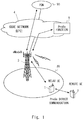
- Fig. 1 shows a configuration example of a radio communication system according to this embodiment.
- Both a relay UE 1 and a Remote UE 2 are UEs capable of providing ProSe (i.e., ProSe-enabled UEs), and they perform ProSe direct communication (inter-terminal direct communication) between them.
- the Relay UE 1 relays unicast traffic (downlink and uplink) between the Remote UE 2 and a network (eNodeB 3 and EPC 4).
- the Relay UE 1 attaches to the EPC 4, establishes a PDN connection for communicating with a ProSe function entity 9, and communicates with the ProSe function entity 9 to start the ProSe direct communication.
- the Relay UE 1 may use a ProSe discovery service provided by the ProSe function entity 9.
- the Relay UE 1 may receive from the ProSe function entity 9 a message indicating permission for the Relay UE 1 to activate ProSe discovery or ProSe direct communication.
- the Relay UE 1 may receive, from the ProSe function entity 9, configuration information (e.g., designation of radio resources and transmission power) for ProSe discovery or ProSe direct communication.
- the Relay UE 1 may further establish a PDN connection for communicating with another Packet Data Network (PDN) 90 that is different from the ProSe function entity 9, and may communicate with the PDN 90.
- PDN Packet Data Network
- the Remote UE 2 communicates with the ProSe function entity 9 or another PDN 90 through the ProSe direct communication path (inter-terminal direct communication path) with the Relay UE 1.
- the Remote UE 2 is located outside of a coverage area (cell) 30 of the eNodeB 3 (i.e., out of coverage).
- the Remote UE 2 may be located inside of the coverage area 30 (i.e., in coverage) and may select the direct communication with the Relay UE 1, instead of the direct communication with the eNodeB 3, based on certain conditions (e.g., selection by a user).
- Fig. 2 shows reference points (PC3 and PC5) regarding ProSe in the radio communication system according to this embodiment, and also shows reference points for the user plane of the EPS that are used for transmitting ProSe control signaling at the PC3 reference point. Each reference point is also called an "interface”.
- User IP packets for the Relay UE 1 include uplink user IP packets originating from the Relay UE 1 and downlink user IP packets destined for the Relay UE 1.
- user IP packets for the Relay UE 1 carry ProSe control signaling and are transferred between the Relay UE 1 and the ProSe function entity 9.
- the PC3 reference point depends on the user plane of the E-UTRAN and the EPC, and accordingly the ProSe control signaling is transferred on this user plane.
- the Relay UE 1 may transmit and receive user IP packets to and from another PDN 90, which is different from the ProSe function entity 9.
- the Relay UE 1 establishes a PDN connection with a PDN including the ProSe function entity 9 to exchange ProSe control signaling with the ProSe function entity 9 through the PC3 reference point.
- One or more EPS bearers regarding the PDN connection between the Relay UE1 and the PDN including the ProSe function entity 9 are established between the Relay UE 1 and a P-GW 6 for the Relay UE 1.
- the P-GW 6 for the Relay UE 1 is associated with the Relay UE 1 and is also associated with the Access Point Name (APN) corresponding to the PDN including the ProSe function entity 9.
- APN Access Point Name
- Each EPS bearer established between the P-GW 6 and the Relay UE 1 consists of: a data radio bearer (DRB) at a Long Term Evolution (LTE)-Uu reference point between the Relay UE 1 and the eNodeB 3; an S1 bearer at an S1-U reference point between the eNodeB 3 and an S-GW 5; and an S5 bearer at an S5 reference point between the S-GW 5 and the P-GW 6.
- DRB data radio bearer
- LTE Long Term Evolution
- the Relay UE 1 communicates with the eNodeB 3 in a radio access network (i.e., U-TRAN) through the LTE-Uu reference point.
- the LTE-Uu reference point is a radio interface and includes signaling radio bearers (SRBs) carrying messages regarding a control connection (i.e., Radio Resource Control (RRC) connection) and data radio bearers (DRBs) carrying downlink and uplink user IP packets.
- SRBs signaling radio bearers
- RRC Radio Resource Control
- DRBs data radio bearers
- the eNodeB 3 communicates with the S-GW 5 for the Relay UE 1 via the S1-U reference point.
- the S1-U reference point uses the GPRS Tunneling Protocol User Plane (GTP-U).
- GTP-U GPRS Tunneling Protocol User Plane
- the eNodeB 3 establishes one or more S1 bearers (i.e., GTP tunnels) with the S-GW 5 at the S1-U reference point and transfers downlink and uplink user IP packets for the Relay UE1 through these S1-U bearers.
- the one or more S1-U bearers are mapped to the one or more DRBs, which are established between the Relay UE 1 and the eNodeB 3, on a one-to-one basis.
- the S-GW 5 for the Relay UE 1 communicates with the P-GW 6 for the Relay UE 1 through the S5 reference point.
- the S5 reference point uses the GTP-U to transfer user IP packets and uses the GTP Control Plane version 2 (GTP-Cv2) to perform management of the GTP tunnel, such as establishment and release of the GTP tunnel.
- GTP-Cv2 GTP Control Plane version 2
- the S-GW 5 establishes one or more S5 bearers (i.e., GTP tunnels) with the P-GW 6 at the S5 reference point and transfers downlink and uplink user IP packets for the Relay UE 1 through these S5 bearers.
- the one or more S5 bearers are mapped to the one or more S1 bearers, which are established between the eNodeB 3 and the S-GW 5, on a one-to-one basis.
- the P-GW 6 for the Relay UE 1 communicates with the ProSe function entity 9 through an SGi reference point. Specifically, the P-GW 6 receives uplink user IP packets, which have been transmitted from the Relay UE 1 and are destined for the ProSe function entity 9, through the S5 bearers (GTP tunnel) between the P-GW 6 and the S-GW 5, and transmits them to the ProSe function entity 9 through the SGi reference point.
- GTP tunnel S5 bearers
- the P-GW 6 receives downlink user IP packets, which have been transmitted from the ProSe function entity 9 and are destined for the Relay UE 1, through the SGi reference point, and transmits them in the S5 bearer (i.e., GTP tunnel) for the Relay UE 1 between the P-GW 6 and the S-GW 5.
- the P-GW 6 may communicate not only with the ProSe function entity 9, but also with another PDN 90, which is not shown in Fig. 2 , through the SGi reference point.
- User IP packets for the Remote UE 2 include uplink user IP packets originating from the Remote UE 2 and downlink user IP packets destined for the Remote UE 2.
- user IP packets for the Remote UE 2 carry ProSe control signaling and are transferred between the Remote UE 2 and the ProSe function entity 9 (i.e., transferred at the PC3 reference point).
- the Remote UE 2 may transmit and receive user IP packets to and from another PDN 90, which is different from the ProSe function entity 9.
- the Remote UE 2 establishes a ProSe direct communication path with the Relay UE 1 to transmit and receive user IP packets (e.g., user IP packets containing ProSe control signaling between the ProSe function entity 9 and the Remote UE 2 on the PC3 reference point).
- the Remote UE 2 may request the Relay UE 1 to provide communication with the ProSe function entity 9.
- the Relay UE 1 has a function of terminating a GTP tunnel to transfer user IP packets for the Remote UE 2.
- the Relay UE 1 according to this embodiment has the S5 reference point with a P-GW 8 for the Remote UE 2, exchanges GTP-Cv2 signaling with the P-GW 8, establishes a GTP tunnel (S5 bearer) to the P-GW 8, and transfers user IP packets for the Remote UE 2 through this GTP tunnel (S5 bearer).
- this GTP tunnel (S5 bearer) between the P-GW 8 for the Remote UE 2 and the Relay UE 1 is established so as to pass through the EPS bearer between the P-GW 6 for the Relay UE 1 and the Relay UE 1 (i.e., the DRB between the Relay UE 1 and the eNodeB 3, the S1 bearer (GTP tunnel) between the eNodeB 3 and the S-GW 5, and the S5 bearer (GTP tunnel) between the S-GW 5 and the P-GW 6).
- the EPS bearer between the P-GW 6 for the Relay UE 1 and the Relay UE 1
- the S1 bearer GTP tunnel
- S5 bearer GTP tunnel
- GTP tunnel packets regarding the GTP tunnel (S5 bearer) between the P-GW 8 for the Remote UE 2 and the Relay UE 1 are transferred through the EPS bearer between the P-GW 6 for the Relay UE 1 and the Relay UE 1. That is, GTP tunnel packets regarding the GTP tunnel between the P-GW 8 and the Relay UE 1 are treated in the same manner as user IP packets for the Relay UE 1 are treated.
- each GTP tunnel packet regarding the GTP tunnel between the P-GW 8 and the Relay UE 1 is an IP packet containing a payload storing a GTP Protocol Data Unit (GTP PDU) that encapsulates a user IP packet for the Remote UE 2 with a GTP header of this GTP tunnel.
- GTP PDU GTP Protocol Data Unit
- the GTP PDU carrying a user IP packet is also referred to as a "GTP-U message" or a "G-PDU".
- the P-GW 8 for the Remote UE 2 communicates with the Relay UE 1 via the S5 reference point, and communicates with the ProSe function entity 9 via the SGi reference point. Specifically, the P-GW 8 receives uplink user IP packets, which have been transmitted from the Remote UE 2 and is destined for the ProSe function entity 9, through the S5 bearer (i.e., GTP tunnel) for the Remote UE 2 between the P-GW 8 and the Relay UE 1, and transmits them to the ProSe function entity 9 through the SGi reference point.
- S5 bearer i.e., GTP tunnel
- the P-GW 8 receives downlink user IP packets, which have been transmitted from the ProSe function entity 9 and is destined for the Remote UE2, through the SGi reference point, and transmits them in the S5 bearer (GTP tunnel) for the Remote UE 2 between the P-GW 8 and the Relay UE 1.
- the P-GW 8 may communicate not only with the ProSe function entity 9, but also with another PDN 90, which is not shown in Fig. 2 , through the SGi reference point.
- the P-GW 8 for the Remote UE 2 may be the same P-GW as the P-GW 6 for the Relay UE 1.
- the APN for the Remote UE 2 to communicate with the ProSe function entity 9 or with another PDN 90 may be associated with the P-GW 6 with which the APN for the Relay UE 1 to communicate with the ProSe function entity 9 or another PDN 90 is associated.
- Fig. 3 is a diagram showing an example of a user-plane architecture (bearer structure) according to this embodiment.
- the Relay UE 1 terminates an S5 bearer (GTP tunnel) 320 for the Remote UE 2.
- the S5 bearer (GTP tunnel) 320 for the Remote UE 2 transfers user IP packets for the Remote UE 2 (i.e., IP flow 340).
- the S5 bearer (GTP tunnel) 320 is established so as to pass through an EPS bearer 300 between the P-GW 6 for the Relay UE 1 and the Relay UE 1.
- GTP tunnel packets of the S5 bearer 320 carrying user IP packets for the Remote UE 2 are transferred through the EPS bearer 300.
- the EPS bearer 300 consists of a DRB 301 between the Relay UE 1 and the eNodeB 3, an S1 bearer 302 between the eNodeB 3 and the S-GW 5, and an S5 bearer 303 between the S-GW 5 and the P-GW 6.
- Fig. 3 shows a transfer of the downlink IP flow 340 from the ProSe function entity 9 to the Remote UE 2
- an uplink IP flow is also transferred through the S5 bearer (GTP tunnel) between the P-GW 8 for the Remote UE 2 and the Relay UE 1.
- Uplink and downlink IP flows between another PDN 90 and the Remote UE 2 may also be transferred through an S5 bearer (GTP tunnel) between the P-GW 8 for the Remote UE 2 and the Relay UE 1, like in Fig. 3 .
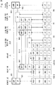
- Fig. 4 shows a protocol stack regarding the PC3 reference point for the Remote UE 2 to communicate with the ProSe function entity 9.
- ProSe control signaling on the PC3 reference point is transferred on the user plane.
- an application layer 401 of the Remote UE 2 communicates with an application layer 402 of the ProSe function entity 9 to exchange ProSe control signaling on the PC3 reference point.
- the application layer 401 of the Remote UE 2 may communicate with an application layer of a node in another PDN 90.
- An IP layer 421 of the Remote UE 2 transmits or receives user IP packets originating from, or destined for, the Remote UE 2 to or from an IP layer 422 of the ProSe function entity 9.
- GTP tunnel S5 bearer
- GTP layer 441 of the Relay UE 1 GTP layer 441 of the Relay UE 1
- GTP layer 442 of the P-GW 8 GTP layer 442 of the P-GW 8 for the Remote UE 2.
- each IP packet (GTP tunnel packet) encapsulating a user IP packet for the Remote UE 2 is further encapsulated in GTP layers of the eNodeB 3, the S-GW 5, and the P-GW 6 so as to be transferred through the EPS bearer between the Relay UE 1 and the P-GW 6 for the Relay UE 1.
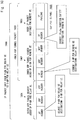
- Fig. 5 shows a configuration example of a downlink IP packet 500 sent from the P-GW 6 for the Relay UE 1 to the S-GW 5 for the Relay UE 1 at the S5 reference point.
- the P-GW 6 for the Relay UE 1 receives a GTP tunnel packet 503 from the P-GW 8 for the Remote UE 2 at the SGi reference point.
- the GTP tunnel packet 503 is an IP packet to be transmitted to the Relay UE 1 from the P-GW 8, and encapsulates a downlink user IP packet 501 destined for the Remote UE 2 with a GTP tunnel header 502.
- the downlink user IP packet 501 is transmitted to the Remote UE 2 by the ProSe function entity 9 or a node in another PDN 90.
- the GTP tunnel header 502 includes a GTP header, a User Datagram Protocol (UDP) header, and an IP header, and is added to the user IP packet 501 by the P-GW 8 for the Remote UE 2.
- a GTP PDU (G-PDU) 505 consists of the GTP header and the user IP packet 501.
- the IP header contained in the GTP tunnel header 502 designates the P-GW 8 for the Remote UE 2 as the source, and designates the Relay UE 1 as the destination.
- the P-GW 6 for the Relay UE 1 generates the downlink IP packet 500 containing the GTP tunnel packet 503 in the payload thereof.
- the P-GW 6 adds, to the GTP tunnel packet 503 (inner GTP tunnel packet), an outer GTP tunnel header 504 including a GTP header, a User Datagram Protocol (UDP) header, and an IP header.
- the IP header in the outer GTP tunnel header 504 designates the P-GW 6 for the Relay UE 1 as the source, and designates the S-GW 5 for the Relay UE 1 as the destination.
- the Relay UE 1 transmits and receives user IP packets for the Remote UE 2 destined for, or originating from, the Remote UE 2 via the ProSe direct communication (inter-terminal direct communication). Further, the Relay UE 1 has a capability of terminating a GTP tunnel.
- the Relay UE 1 is configured to establish a GTP tunnel between the Relay UE 1 and the P-GW 8 for the Remote UE 2 so as to pass through its own EPS bearer (i.e., the EPS bearer between the Relay UE 1 and the P-GW 6 for the Relay UE 1), and transfer user IP packets (e.g., user IP packets carrying ProSe control signaling) for the Remote UE 2 through this GTP tunnel.
- GTP tunnel packets encapsulating user IP packets for the Remote UE 2 are transferred through the EPS bearer of the Relay UE 1 as described above with reference to Figs. 2 to 4 .
- the P-GW 8 for the Remote UE 2 can manage the user-plane IP address of the Remote UE2 and contexts regarding the EPS bearer of the Remote UE 2 (e.g., Tunnel Endpoint ID (TEID) of the S5 bearer, APN, EPS bearer ID, and bearer QoS). This contributes to, for example, the continuity of services for the Remote UE 2.
- TEID Tunnel Endpoint ID
- the P-GW 8 for the Remote UE 2 can modify and reuse the GTP tunnel (e.g., the S5 bearer (GTP tunnel) 320 shown in Fig. 3 ) which has already been established for the Remote UE 2.
- the P-GW 8 for the UE 2 can continue to use, for example, the user-plane IP address of the Remote UE 2, the TEID of the P-GW 8 regarding the S5 bearer, and the APN.
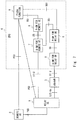
- Fig. 6 is a diagram showing an example of a bearer structure when the Remote UE 2 is out of coverage (i.e., when the Remote UE 2 uses ProSe direct communication with the Relay UE 1) and an example of a bearer structure when the Remote UE 2 is in coverage (i.e., when the Remote UE 2 uses communication with the E-UTRAN (eNodeB 3)).
- eNodeB 3 E-UTRAN
- user IP packets for the Remote UE 2 are transferred through a ProSe direct communication path 601, an S5 bearer (GTP tunnel) 602 between the Relay UE 1 and the P-GW 8 for the Remote UE 2, and an SGi reference point 603 of the P-GW 8.
- the Remote UE 2 when the Remote UE 2 is in coverage, user IP packets for the Remote UE 2 are transferred through, for example, a DRB 621 between the Remote UE 2 and the eNodeB 3, an S1 bearer (GTP tunnel) 622 between the eNodeB 3 and the S-GW 5 for the Relay UE 1, an S5 bearer (GTP tunnel) 623 between the S-GW 5 for the Relay UE 1 and the P-GW 8 for the Remote UE 2, and the SGi reference point 603 of the P-GW 8.
- the S1 bearer (GTP tunnel) 622 may be established in another S-GW, instead of the S-GW 5 for the Relay UE 1. It should be noted, as shown in Fig.
- the P-GW 8 for the Remote UE 2 terminates the S5 bearer (602 and 623) for the Remote UE 2 when the Remote UE 2 is in coverage, as well as when the Remote UE 2 is out of coverage.
- the P-GW 8 for the Remote UE 2 modifies the S5 bearer 602 when the Remote UE 2 is out of coverage, so that the P-GW 8 can obtain the S5 bearer 623 when the Remote UE 2 is in coverage.
- the first embodiment provides an example in which the Relay UE 1 terminates an S5 bearer.
- this embodiment provides an example in which the Relay UE 1 terminates an S1 bearer.
- a configuration example of a radio communication system according to this embodiment is similar to that shown in Fig. 1 described above in the first embodiment.
- Fig. 7 shows reference points (PC3 and PC5) regarding ProSe in the radio communication system according to this embodiment, and also shows reference points of for the user plane of the EPS that are used for transmitting ProSe control signaling at the PC3 reference point.
- Fig. 7 differs from Fig. 2 described above in that the Relay UE 1 has an S1-U reference point with an S-GW 7 for the Remote UE 2 and the P-GW 8 for the Remote UE 2 has an SGi reference point with the S-GW7 for the Remote UE 2.
- the Relay UE 1 exchanges S1-AP signaling with an Mobility Management Entity (MME) (not shown), establishes a GTP tunnel (S1 bearer) with the S-GW 7 for the Remote UE 2, and transfers user IP packets for the Remote UE 2 through this GTP tunnel (S1 bearer).
- MME Mobility Management Entity
- the P-GW 8 for the Remote UE 2 may be the same P-GW as the P-GW 6 for the Relay UE 1.
- the S-GW 7 for the Remote UE 2 may be the same P-GW as the S-GW 5 for the Relay UE 1.
- Fig. 8 is a diagram showing an example of a user-plane architecture (bearer structure) according to this embodiment.
- the Relay UE 1 terminates an S1 bearer (GTP tunnel) 821 for the Remote UE 2.
- the S1 bearer (GTP tunnel) 821 for the Remote UE 2 is connected to an S5 bearer 822 in the S-GW 7 to transfer user IP packets for the Remote UE 2 (i.e., IP flow 840).
- the S1 bearer (GTP tunnel) 820 is established so as to pass through an EPS bearer 800 between the Relay UE 1 and the P-GW 6 for the Relay UE 1.
- GTP tunnel packets of the S1 bearer 820 carrying user IP packets for the Remote UE 2 are transferred through the EPS bearer 800.
- the EPS bearer 800 consists of a DRB 801 between the Relay UE 1 and the eNodeB 3, an S1 bearer between the eNodeB 3 and the S-GW 5, and a S5 bearer (802) between the S-GW 5 and the P-GW 6.
- Fig. 8 shows a transfer of the downlink IP flow 840 from the ProSe function entity 9 to the Remote UE 2
- an uplink IP flow is also transferred through the S1 bearer (GTP tunnel) between the S-GW 7 for the Remote UE 2 and the Relay UE 1.
- Uplink and downlink IP flows between the Remote UE 2 and another PDN 90 may also be transferred through an S5 bearer (GTP tunnel) between the S-GW 7 for the Remote UE 2 and the Relay UE 1, like in Fig. 8 .
- Fig. 9 shows a protocol stack regarding the PC3 reference point for the Remote UE 2 to communicate with the ProSe function entity 9.
- An application layer 901 of the Remote UE 2 communicates with an application layer 902 of the ProSe function entity 9 to exchange ProSe control signaling on the PC3 reference point.
- the application layer 901 of the Remote UE 2 may communicate with an application layer of a node in another PDN 90.
- An IP layer 921 of the Remote UE 2 transmits or receives user IP packets originating from, or destined for, the Remote UE 2 to or from an IP layer 922 of the ProSe function entity 9.
- GTP tunnel S1 bearer
- GTP layer 941 of the Relay UE 1 GTP layer 941 of the Relay UE 1
- GTP layer 942 of the S-GW 7 GTP layer 942 of the S-GW 7 for the Remote UE 2.
- each IP packet (GTP tunnel packet) encapsulating a user IP packet for the Remote UE 2 is further encapsulated in GTP layers of the eNodeB 3, the S-GW 5, and the P-GW 6 so as to be transferred through the EPS bearer between the Relay UE 1 and the P-GW 6 for the Relay UE 1.
- Fig. 10 shows a configuration example of a downlink IP packet 1000 sent from the P-GW 6 for the Relay UE 1 to the S-GW 5 at the S5 reference point.
- the downlink IP packet 1000 includes an outer GTP tunnel header 1004 and an inner GTP tunnel packet 1003.
- the inner GTP tunnel packet 1003 includes an inner GTP tunnel header 1002 and a downlink user IP packet 1001 for the Remote UE 2.
- a GTP PDU (G-PDU) 1005 consists of the GTP header and the user IP packet 1001.
- the configuration of the downlink IP packet 1000 is the same as that of the downlink IP packet 500 shown in Fig. 5 , except that the IP header within the inner GTP tunnel header 1002 designates the S-GW 7 for the Remote UE 2 as the source.
- the Relay UE 1 transfers user IP packets, destined for, or originating from, the Remote UE 2, through the ProSe direct communication (inter-terminal direct communication). Further, the Relay UE 1 has a capability of terminating a GTP tunnel and is configured to establish a GTP tunnel to the S-GW 7 for the Remote UE 2, which passes through its own EPS bearer (i.e., the EPS bearer between the Relay UE 1 and the P-GW 6 for the Relay UE 1), and transfer user IP packets for the Remote UE 2 (e.g., user IP packets carrying ProSe control signaling) in the established GTP tunnel.
- EPS bearer i.e., the EPS bearer between the Relay UE 1 and the P-GW 6 for the Relay UE 1
- GTP tunnel packets each encapsulating a user IP packet for the Remote UE 2, are transferred through the EPS bearer of the Relay UE 1 as described above with reference to Figs. 7 to 9 .
- Such a user-plane architecture can contribute to, for example, the continuity of services for the Remote UE 2, like in the first embodiment.
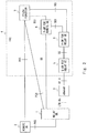
- Fig. 11 shows a configuration example of the Relay UE 1.
- the Relay UE 1 includes an LTE transceiver 11, a ProSe transceiver 12, a processor 13, and a memory 14.
- the LTE transceiver 11 is configured to communicate with the E-UTRAN (eNodeB 3).
- the ProSe transceiver 12 is used for ProSe direct communication (inter-terminal direct communication) with the Remote UE 2.
- the processor 13 loads software (computer program) from the memory 14 and executes this software, thereby performing the operations of the Relay UE 1 as described in the above embodiments.
- the processor 13 may be, for example, a microprocessor, a Micro Processing Unit (MPU), or a Central Processing Unit (CPU).
- the processor 13 may include a plurality of processors.
- the memory 14 consists of a volatile memory and a non-volatile memory.
- the volatile memory is, for example, a Static Random Access Memory (SRAM), a Dynamic RAM (DRAM), or a combination thereof.
- the non-volatile memory is, for example, a Mask Read Only Memory (MROM), a Programmable ROM (PROM), a flash memory, a hard disk drive, or a combination thereof.
- the memory 14 may include a storage located remotely from the processor 13. In this case, the processor 13 may access the memory 14 via an I/O interface (not shown).
- the memory 14 is used to store software modules including a GTP module 15.
- the GTP module 15 includes instructions and data necessary for establishing up a GTP tunnel to the P-GW 8 or S-GW 7 for the Remote UE 2 and for executing processing of transferring user IP packets for the Remote UE 2 through the GTP tunnel.
- the processor 13 loads software modules including the GTP module 15 from the memory 14 and executes these software modules, thereby performing the operations of the Relay UE 1 as described in the above embodiments.
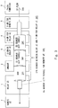
- Fig. 12 shows a configuration example of the P-GW 6 for the Relay UE 1.
- the P-GW 6 includes a network interface 61, a processor 62, and a memory 63.
- the network interface 61 is used to communicate with network nodes (e.g., S-GW 5, P-GW 8, ProSe function entity 9, MME, and Home Subscriber Server (HSS)).
- the network interface 61 may include, for example, a network interface card (NIC) conforming to the IEEE 802.3 series.
- the processor 62 loads software (computer program) from the memory 63 and executes this software, thereby performing the operations of the P-GW 6 as described in the above embodiments.
- the processor 62 may be, for example, a microprocessor, an MPU, or a CPU.
- the processor 62 may include a plurality of processors.
- the memory 63 consists of a volatile memory and a non-volatile memory.
- the volatile memory is, for example, an SRAM, a DRAM, or a combination thereof.
- the non-volatile memory is, for example, an MROM, a PROM, a flash memory, a hard disk drive, or a combination thereof.
- the memory 63 may include a storage that is located physically apart from the processor 62. In this case, the processor 62 may access the memory 63 via the network interface 61 or another I/O interface (not shown).
- the memory 63 is used to store software modules including a GTP module 64.
- the GTP module 64 includes instructions and data for establishing up an S1 bearer (GTP tunnel) to the S-GW 5 and for executing processing of transmitting, in the S1 bearer, GTP tunnel packets received from the P-GW 8 or S-GW 7 for the Remote UE 2 via the SGi reference point.
- the processor 62 loads software modules including the GTP module 64 from the memory 63 and executes these software modules, thereby performing the operations of the P-GW 6 for the Relay UE 1 as described in the above embodiments.
- each of the processors included in the Relay UE 1 and the P-GW 6 executes one or more programs including instructions to cause a computer to perform an algorithm described with reference to the drawings.
- These programs can be stored and provided to a computer using various types of non-transitory computer readable media.
- the non-transitory computer readable media includes various types of tangible storage media.
- non-transitory computer readable media examples include a magnetic recording medium (such as a flexible disk, a magnetic tape, and a hard disk drive), a magneto-optic recording medium (such as a magneto-optic disk), a CD-ROM (Compact Disc Read Only Memory), CD-R, CD-R/W, and a semiconductor memory (such as a mask ROM, a PROM (Programmable ROM), an EPROM (Erasable PROM), a flash ROM, and a RAM (Random Access Memory)).
- these programs can be supplied to computers by using various types of transitory computer readable media. Examples of the transitory computer readable media include an electrical signal, an optical signal, and an electromagnetic wave.
- the transitory computer readable media can be used to supply programs to a computer through a wired communication path such as an electrical wire and an optical fiber, or a wireless communication path.
- the Relay UE 1 may handle GTP-C signaling over the S11 and S5 interfaces, which is traditionally performed by an S-GW, and also handle S1-AP signaling over the S1-MME interface, which is traditionally performed by an eNodeB. Instead, new signaling may be defined for sending, to the Relay UE 1, information about the GTP tunnel (i.e., S5 or S1 bearer) endpoint at the S-GW 7 or P-GW 8 for the Remote UE 2 and for sending, to the S-GW 7 or the P-GW 8, information about the GTP tunnel endpoint at the Relay UE 1. For example, the Relay UE 1 may exchange the GTP tunnel endpoint information by exchanging Non-Access Stratum (NAS) messages with an MME.
- NAS Non-Access Stratum
- UMTS Universal Mobile Telecommunications System
- HRPD High Rate Packet Data
- GSM Global System for Mobile communications
- GPRS General packet radio service
Landscapes
- Engineering & Computer Science (AREA)
- Computer Networks & Wireless Communication (AREA)
- Signal Processing (AREA)
- Mobile Radio Communication Systems (AREA)
Applications Claiming Priority (2)
| Application Number | Priority Date | Filing Date | Title |
|---|---|---|---|
| JP2014206189 | 2014-10-07 | ||
| PCT/JP2015/003574 WO2016056154A1 (fr) | 2014-10-07 | 2015-07-15 | Terminal relais sans fil, dispositif de réseau central, et procédés correspondants |
Publications (2)
| Publication Number | Publication Date |
|---|---|
| EP3206457A1 true EP3206457A1 (fr) | 2017-08-16 |
| EP3206457A4 EP3206457A4 (fr) | 2018-06-27 |
Family
ID=55652802
Family Applications (1)
| Application Number | Title | Priority Date | Filing Date |
|---|---|---|---|
| EP15849458.3A Withdrawn EP3206457A4 (fr) | 2014-10-07 | 2015-07-15 | Terminal relais sans fil, dispositif de réseau central, et procédés correspondants |
Country Status (6)
| Country | Link |
|---|---|
| US (1) | US10505621B2 (fr) |
| EP (1) | EP3206457A4 (fr) |
| JP (1) | JPWO2016056154A1 (fr) |
| KR (1) | KR101896394B1 (fr) |
| CN (1) | CN106797674A (fr) |
| WO (1) | WO2016056154A1 (fr) |
Families Citing this family (13)
| Publication number | Priority date | Publication date | Assignee | Title |
|---|---|---|---|---|
| US10555259B2 (en) * | 2015-03-24 | 2020-02-04 | Lg Electronics Inc. | Method performed by a terminal for performing a communication operation of another terminal in a wireless communication system and terminal using method |
| US10834179B2 (en) * | 2015-03-30 | 2020-11-10 | Telefonaktiebolaget Lm Ericsson (Publ) | Load balancing |
| WO2017028294A1 (fr) * | 2015-08-20 | 2017-02-23 | 华为技术有限公司 | Procédé et appareil de traitement de données |
| US10205507B2 (en) * | 2015-08-28 | 2019-02-12 | Tejas Networks, Ltd. | Relay architecture, relay node, and relay method thereof |
| JPWO2017051503A1 (ja) * | 2015-09-24 | 2018-07-12 | パナソニック インテレクチュアル プロパティ コーポレーション オブ アメリカPanasonic Intellectual Property Corporation of America | 通信システム、リレー端末、リモート端末及び通信制御方法 |
| EP3376788B1 (fr) * | 2015-12-31 | 2019-09-18 | Huawei Technologies Co., Ltd. | Procédé permettant à un équipement d'utilisateur (ue) d'accéder à un réseau, entité de réseau central, station de base, et premier ue |
| WO2018044144A1 (fr) * | 2016-09-05 | 2018-03-08 | 엘지전자(주) | Procédé d'exécution d'une procédure de demande de service dans un système de communication sans fil, et dispositif associé |
| CN109417695B (zh) * | 2017-01-10 | 2020-10-23 | 华为技术有限公司 | 一种通信路径转换方法及设备 |
| CN111480353B (zh) * | 2017-12-18 | 2023-10-27 | 皇家Kpn公司 | 用于在远程ue与电信网络之间建立信令连接的方法和设备 |
| CN110035566B (zh) * | 2018-01-12 | 2023-04-28 | 华为技术有限公司 | 数据传输方法、网络设备及存储介质 |
| JP7173461B2 (ja) * | 2018-06-11 | 2022-11-16 | さくらインターネット株式会社 | ゲートウェイ装置 |
| CN110650550B (zh) * | 2019-09-24 | 2021-05-07 | 展讯通信(上海)有限公司 | 数据传输方法、ue及计算机可读存储介质 |
| EP4162716B1 (fr) * | 2020-07-24 | 2026-02-11 | Apple Inc. | Procédures d'échange de données pour appareils sans fil relais |
Family Cites Families (10)
| Publication number | Priority date | Publication date | Assignee | Title |
|---|---|---|---|---|
| WO2002007461A2 (fr) * | 2000-07-17 | 2002-01-24 | Nokia Corporation | Procedes et systemes d'acheminement d'une signalisation de commande apres transfert d'un reseau ip a commutation par paquets a un reseau cellulaire a commutation de circuits et vice-versa |
| US9160566B2 (en) | 2009-04-10 | 2015-10-13 | Qualcomm Incorporated | QOS mapping for relay nodes |
| KR100968037B1 (ko) * | 2009-04-21 | 2010-07-07 | 엘지전자 주식회사 | 무선 통신 시스템에서 무선 베어러를 관리하는 방법 및 장치 |
| US8588138B2 (en) * | 2009-07-23 | 2013-11-19 | Qualcomm Incorporated | Header compression for relay nodes |
| EP2355608B1 (fr) * | 2009-10-30 | 2016-03-09 | Institute for Imformation Industry | Noeud évolué de donneur, noeud de relais et son procédé de communication |
| CA2773126C (fr) * | 2009-11-02 | 2015-12-29 | Lg Electronics Inc. | Identification de correlation pour acces ip local |
| CN102098725B (zh) * | 2009-12-15 | 2015-07-22 | 中兴通讯股份有限公司 | 一种服务网关与中继终端间传输数据的系统及方法 |
| KR102006512B1 (ko) * | 2011-11-04 | 2019-08-01 | 텔레폰악티에볼라겟엘엠에릭슨(펍) | 피디엔 접속을 확립하고 또한 사용하기 위한 방법 및 장치 |
| CN104066200B (zh) * | 2013-03-21 | 2020-11-06 | 北京三星通信技术研究有限公司 | 一种ue间端到端通信的实现方法及用户设备 |
| US10536213B2 (en) * | 2013-07-08 | 2020-01-14 | Nokia Solutions And Networks Oy | Establishment of packet data network connection via relay user equipment |
-
2015
- 2015-07-15 CN CN201580054585.8A patent/CN106797674A/zh active Pending
- 2015-07-15 EP EP15849458.3A patent/EP3206457A4/fr not_active Withdrawn
- 2015-07-15 JP JP2016552806A patent/JPWO2016056154A1/ja active Pending
- 2015-07-15 KR KR1020177008330A patent/KR101896394B1/ko active Active
- 2015-07-15 US US15/515,708 patent/US10505621B2/en active Active
- 2015-07-15 WO PCT/JP2015/003574 patent/WO2016056154A1/fr not_active Ceased
Also Published As
| Publication number | Publication date |
|---|---|
| US10505621B2 (en) | 2019-12-10 |
| CN106797674A (zh) | 2017-05-31 |
| KR20170048457A (ko) | 2017-05-08 |
| WO2016056154A1 (fr) | 2016-04-14 |
| KR101896394B1 (ko) | 2018-09-10 |
| EP3206457A4 (fr) | 2018-06-27 |
| JPWO2016056154A1 (ja) | 2017-07-27 |
| US20170302360A1 (en) | 2017-10-19 |
Similar Documents
| Publication | Publication Date | Title |
|---|---|---|
| US10505621B2 (en) | Relay radio terminal, core network apparatus, and method therefor | |
| JP6721090B2 (ja) | ユーザー装置(ue)および方法 | |
| US11102826B2 (en) | Terminal device, base station device, MME, and communication control method | |
| TWI587725B (zh) | 於封包行動網路中支援資料傳輸的方法以及其使用者設備、ran節點與使用者平面cn節點 | |
| JP5816743B2 (ja) | セルラネットワークとwlanとを統合したネットワーク状況下での通信の方法 | |
| WO2021236894A1 (fr) | Gestion de connectivité de relais de liaison latérale | |
| CN102652412B (zh) | 一种用于在机器对机器通信系统中进行数据传输的方法及其设备 | |
| TW201735715A (zh) | 用於中繼傳輸的方法和裝置以及中繼終端設備 | |
| CN102187730A (zh) | 用于LTE中的自回传的QoS管理 | |
| TW201701616A (zh) | 用於處理漫遊至經造訪網路中之使用者設備之方法及節點 | |
| KR20140134627A (ko) | 디바이스-투-디바이스 통신 시스템에서 아이피 세션 연속성 시스템 및 방법 | |
| JP2022549953A (ja) | データパケット送信方法および装置 | |
| US10542461B2 (en) | Apparatuses and methods therein for relaying an ongoing data session | |
| CN114631394B (zh) | 一种通信方法及装置 | |
| CN116326168A (zh) | 无线通信中的信令交换方案 | |
| EP3510829B1 (fr) | Contournement de réseaux de données par paquets externes dans une communication mobile à mobile | |
| US12294936B2 (en) | Communicating over a local area network connection between a radio access node and a user equipment relay | |
| US9936402B2 (en) | Methods and systems for managing relays in LTE based communication networks | |
| WO2018084080A1 (fr) | Station de base, passerelle, dispositif, procédé, programme, et support d'enregistrement | |
| KR101665934B1 (ko) | 다중 무선전송기술이 적용된 무선 백홀 시스템에서의 데이터 라우팅 방법 | |
| CN115553054B (zh) | 用于通信的装置和方法 | |
| WO2015144213A1 (fr) | Procédés et nœuds pour une signalisation de réseau améliorée | |
| WO2023184542A1 (fr) | Procédé et appareil de configuration d'informations et système de communication | |
| JP2016005242A (ja) | 無線通信システム、基地局、通信方法、プログラム | |
| JP2019029964A (ja) | 多重無線伝送技術が適用された無線バックホールシステムにおけるデータルーティング方法 |
Legal Events
| Date | Code | Title | Description |
|---|---|---|---|
| PUAI | Public reference made under article 153(3) epc to a published international application that has entered the european phase |
Free format text: ORIGINAL CODE: 0009012 |
|
| 17P | Request for examination filed |
Effective date: 20170505 |
|
| AK | Designated contracting states |
Kind code of ref document: A1 Designated state(s): AL AT BE BG CH CY CZ DE DK EE ES FI FR GB GR HR HU IE IS IT LI LT LU LV MC MK MT NL NO PL PT RO RS SE SI SK SM TR |
|
| AX | Request for extension of the european patent |
Extension state: BA ME |
|
| DAV | Request for validation of the european patent (deleted) | ||
| DAX | Request for extension of the european patent (deleted) | ||
| A4 | Supplementary search report drawn up and despatched |
Effective date: 20180528 |
|
| RIC1 | Information provided on ipc code assigned before grant |
Ipc: H04W 88/04 20090101AFI20180522BHEP Ipc: H04B 7/155 20060101ALI20180522BHEP Ipc: H04W 88/16 20090101ALI20180522BHEP Ipc: H04W 80/02 20090101ALI20180522BHEP Ipc: H04W 92/04 20090101ALI20180522BHEP |
|
| STAA | Information on the status of an ep patent application or granted ep patent |
Free format text: STATUS: THE APPLICATION HAS BEEN WITHDRAWN |
|
| 18W | Application withdrawn |
Effective date: 20180911 |