EP3206458B1 - Procédé, dispositif et système de communication - Google Patents
Procédé, dispositif et système de communication Download PDFInfo
- Publication number
- EP3206458B1 EP3206458B1 EP15848978.1A EP15848978A EP3206458B1 EP 3206458 B1 EP3206458 B1 EP 3206458B1 EP 15848978 A EP15848978 A EP 15848978A EP 3206458 B1 EP3206458 B1 EP 3206458B1
- Authority
- EP
- European Patent Office
- Prior art keywords
- base station
- small base
- data
- user equipment
- configuration information
- Prior art date
- Legal status (The legal status is an assumption and is not a legal conclusion. Google has not performed a legal analysis and makes no representation as to the accuracy of the status listed.)
- Active
Links
Images



Classifications
-
- H—ELECTRICITY
- H04—ELECTRIC COMMUNICATION TECHNIQUE
- H04W—WIRELESS COMMUNICATION NETWORKS
- H04W48/00—Access restriction; Network selection; Access point selection
- H04W48/20—Selecting an access point
-
- H—ELECTRICITY
- H04—ELECTRIC COMMUNICATION TECHNIQUE
- H04W—WIRELESS COMMUNICATION NETWORKS
- H04W8/00—Network data management
- H04W8/02—Processing of mobility data, e.g. registration information at HLR [Home Location Register] or VLR [Visitor Location Register]; Transfer of mobility data, e.g. between HLR, VLR or external networks
-
- H—ELECTRICITY
- H04—ELECTRIC COMMUNICATION TECHNIQUE
- H04W—WIRELESS COMMUNICATION NETWORKS
- H04W8/00—Network data management
- H04W8/26—Network addressing or numbering for mobility support
-
- H—ELECTRICITY
- H04—ELECTRIC COMMUNICATION TECHNIQUE
- H04W—WIRELESS COMMUNICATION NETWORKS
- H04W88/00—Devices specially adapted for wireless communication networks, e.g. terminals, base stations or access point devices
- H04W88/12—Access point controller devices
-
- H—ELECTRICITY
- H04—ELECTRIC COMMUNICATION TECHNIQUE
- H04W—WIRELESS COMMUNICATION NETWORKS
- H04W24/00—Supervisory, monitoring or testing arrangements
- H04W24/02—Arrangements for optimising operational condition
-
- H—ELECTRICITY
- H04—ELECTRIC COMMUNICATION TECHNIQUE
- H04W—WIRELESS COMMUNICATION NETWORKS
- H04W36/00—Hand-off or reselection arrangements
- H04W36/0005—Control or signalling for completing the hand-off
- H04W36/0083—Determination of parameters used for hand-off, e.g. generation or modification of neighbour cell lists
-
- H—ELECTRICITY
- H04—ELECTRIC COMMUNICATION TECHNIQUE
- H04W—WIRELESS COMMUNICATION NETWORKS
- H04W36/00—Hand-off or reselection arrangements
- H04W36/0005—Control or signalling for completing the hand-off
- H04W36/0083—Determination of parameters used for hand-off, e.g. generation or modification of neighbour cell lists
- H04W36/0085—Hand-off measurements
- H04W36/0094—Definition of hand-off measurement parameters
-
- H—ELECTRICITY
- H04—ELECTRIC COMMUNICATION TECHNIQUE
- H04W—WIRELESS COMMUNICATION NETWORKS
- H04W68/00—User notification, e.g. alerting and paging, for incoming communication, change of service or the like
- H04W68/12—Inter-network notification
-
- H—ELECTRICITY
- H04—ELECTRIC COMMUNICATION TECHNIQUE
- H04W—WIRELESS COMMUNICATION NETWORKS
- H04W76/00—Connection management
- H04W76/10—Connection setup
- H04W76/11—Allocation or use of connection identifiers
Definitions
- the present invention relates to the field of communications, and particularly to communication methods in a mobile communication system.
- a document ( EP 2164270 A1 ) relates to a method for configuring transmission bearer under common status, comprising: radio network controller informs via a signaling a base station the transmission bearer identifier corresponding to the CCCH and SRB1 of the cell governed by the base station; the base station obtains the transmission bearer identifier from the signaling, and returns the corresponding transmission bearer identifier in a response message.
- a document ( WO2014/012192 A1 ) relates to a network system with local cluster, central controller, micro base station and macro base station; the network system includes a macro base station and a plurality of micro base stations; the network system further includes: one or more central controllers, configured to provide base station collaboration, resource management, interference and power coordination, or synchronization for the plurality of micro base stations.
- the overall system performance and radio resource utilization have been improved.
- the dual-connectivity architecture still relies upon the existing macro base station, so if there are a large number of small base stations, then both the communication efficiency, and the experiences of the user equipments will be restricted by the architecture, and consequently can not be optimized.
- a user equipment capable of operating at two frequencies can access a high-rate data transmission service, that is, the capability of the user equipment shall be qualified, a macro base station can only manage those small base stations in its coverage area, etc., thus restricting the communication efficiency, and the experiences of the user equipments, so it is desirable to propose a new architecture and communication method so as to address the issues of the connections and the communication efficiency in the case of a large number of small base stations.
- Embodiments of the invention provide communication methods in a mobile communication system, so as to address the issues of the connections and the communication efficiency in the case of a large number of small base stations.
- a communication method includes:
- the first local controller sends the data bearer configuration information to the first local gateway and/or the at least one first small base station, so that the first local gateway establishes the data transmission channel according to the received data bearer configuration information, and further transmits user data, and the first small base station establishes the data transmission channel according to the received data bearer configuration information, and further transmits user data, so the first local controller directly manages the first small station centrally, and controls the first small base station and the first local gateway centrally to establish a data transmission channel, so that when the user equipment needs to transmit user data, then a data transmission channel will be established without involving any macro base station, and there will be no capability of the user equipment to be qualified, thus addressing the issues of the connections and the communication efficiency in the case of a large number of small base stations.
- the method further includes: sending, by the first local controller, broadcast channel configuration information to the first small base station, so that the first small base station issues common control signaling according to the broadcast channel configuration information.
- the method further includes:
- the method further includes:
- the method further includes:
- the method further includes:
- the method further includes:
- a communication method includes:
- the first local controller sends the data bearer configuration information to the first small base station, so that the first small base station establishes the data transmission channel according to the received data bearer configuration information, and further transmits user data, so the first local controller directly manages the first small station centrally, and controls the first small base station centrally to establish a data transmission channel, so that if the user equipment needs to transmit user data, then a data transmission channel will be established without involving any macro base station, and there will be no capability of the user equipment to be qualified, thus addressing the issues of the connections and the communication efficiency in the case of a large number of small base stations.
- the method further includes:
- the method further includes:
- the method further includes:
- the method further includes:
- the method further includes:
- Embodiments of the invention propose a communication method in which a first local controller generates data bearer configuration information for transmitting the user data, upon determining that there is a user equipment for which a data bearer needs to be established; and the first local controller sends the data bearer configuration information to a first local gateway and/or at least one first small base station, so that the network element entity receiving the data bearer configuration information establishes a data transmission channel according to the data bearer configuration information, where the user equipment is hosted by the first local controller and the first local gateway, and the first small base station serves the user equipment.
- the first local controller transmits the data bearer configuration information to the first local gateway and/or the at least one first small base station, the first local gateway establishes a data transmission channel according to the received data bearer configuration information, and further transmits user data, and the first small base station establishes a data transmission channel according to the received data bearer configuration information, and further transmits user data, so the first local controller directly manages the first small stations centrally, and controls the first small base stations and the first local gateway centrally to establish a data transmission channel, so that if the user equipment needs to transmit user data, then a data transmission channel will be established without involving any macro base station, and there will be no capability of the user equipment to be qualified, thus addressing the issues of the connections and the communication efficiency in the case of a large number of small base stations.
- a network architecture in which the communication method according to the embodiments of the invention is performed will be described, and then communication methods for transmitting the user data in the network architecture; controlling an idle user equipment; configuring a protocol stack; switching in a local controller/local gateway a user equipment between cells, and forwarding data while switching the user equipment between the cells; switching across a local controller/local gateway a user equipment between cells, and forwarding data while switching the user equipment between the cells; etc., will be described in that order.
- the network architecture includes small base stations 21, a local gateway 22, a local controller 23, and a core network controller 24, where:
- the local controller 23 and the local gateway 22 are used as a control-plane anchor and a user-plane anchor of the small base stations 21 respectively that are responsible for handling procedures related to the small base stations. From the perspective of the control plane, the small base stations access a core network through the local controller, and are managed by the core network controller as a result (as shown by control-plane data transmission channels in Fig.2 ). From the perspective of the user plane, the small base stations access the core network through the local gateway, or access the Internet directly (as shown by user-plane data transmission channels or local direct data transmission channels in Fig.2 ).
- the local controller 23 and the local gateway 22 can be two functions of an entity, or can be two nodes with interfaces, although the local controller and the local gateway will be described as two nodes with interfaces in the embodiments of the invention by way of an example.
- the local controller 23 generally functions to act as the control-plane anchor of the small base stations to process control-plane signaling related to the small base stations; to terminate and process core network signaling related to the small base stations; to trigger and manage access control signaling related to a user equipment, and to signaling-interact with the user equipment through the small base stations; to manage and coordinate resources of the small base stations, e.g., to manage operating frequencies, power, and other resources of the small base stations, and to control the base station to or not to send common control signaling, etc.; to manage mobility between the small base stations; to manage mobility across the local controller; and to security-manage the small base stations.
- the local gateway 22 generally functions to act as the user-plane anchor of the small base stations; to perform data forwarding and to switch a path while switching between cells; and to security-manage the user plane.
- the communication method according to the embodiments of the invention will be described primarily from the perspectives of the first local controller, the first small base station, and the first local gateway without any loss of generality.
- the first local gateway is controlled by the first local controller; and the second local gateway is controlled by the second local controller; Both user-plane anchors of the first small base station and the second small base station are the first local gateway, and both control-plane anchors of the first small base station and the second small base station are the first local controller, that is, both the first small base station and the second small base station are hosted by the first local gateway and the first local controller; and A user-plane anchor of the third small base station is the second local gateway, and a control-plane anchor of the third small base station is the second local controller, that is, the third small base station is hosted by the second local gateway and the second local controller.
- a first local controller determines that there is a user equipment for which a data bearer needs to be established.
- step 301 when the user equipment needs to establish a data bearer (for data transmission) and the user equipment is in disconnected, then the user equipment notifies the first local controller of a need for interaction, by establishing a Radio Resource Control (RRC) connection with the first local controller, so that the first local controller knows the need for data transmission, and parameter information for data transmission (e.g., a data transmission rate), and further can determine that the user equipment needs to establish a data bearer, and generate bearer configuration information for the user equipment.
- RRC Radio Resource Control
- the first local controller generates data bearer configuration information for transmitting the user data.
- the bearer configuration information includes a user data transmission rate, and optionally data transmission path information, or information about network element nodes, and information about a network, participating in data transmission.
- the bearer configuration information may include the information about the network element nodes, and the information about the network, participating in data transmission, and if default data transmission path information is present and applied in the first local gateway or the first small base station, then the bearer configuration information may not include the information about the network element nodes, and the information about the network, participating in data transmission.
- the first local controller sends the data bearer configuration information to a first local gateway and at least one first small base station.
- the data bearer configuration information is sent to the at least one first small base station in this step 303.
- the first local controller may alternatively send the data bearer configuration information to only the first local gateway, and at this time, the first local gateway can establish a data transmission channel using the data bearer configuration information; or the first local controller may alternatively send the data bearer configuration information to only the at least one first small base station, and at this time, the first small base station receiving the bearer configuration information can establish a data transmission channel using the data bearer configuration information.
- the first local gateway and the at least one first small base station receive the data bearer configuration information.
- the first local gateway and the at least one first small base station establish data transmission channels according to the data bearer configuration information, where the user equipment is hosted by the first local controller and the first local gateway, and the first small base station serves the user equipment.
- the first local gateway transmits user data over the established data transmission channel
- the first small base station transmits user data over the established data transmission channel
- the first small base station establishes a data transmission channel according to the received data bearer configuration information as follows: the first small base station establishes a data transmission channel with the Internet upon determining that user data are to be transmitted directly over the Internet, according to the received data bearer configuration information.
- the first small base station determines that user data are to be transmitted directly over the Internet here refers to the determination that the first small base station is connected directly with the Internet.
- the first small base station establishes a data transmission channel with the first local gateway upon determining that the first local gateway participates in transmission of user data, according to the received data bearer configuration information.
- the first local gateway establishes a data transmission channel according to the received data bearer configuration information as follows: the first local gateway determines the at least one small base station to participate in transmission of user data, according to the received data bearer configuration information; and
- the first local gateway establishes a data transmission channel with the determined at least one small base station
- first small base station is hosted by the first local gateway and the first local controller.
- the first local gateway further establishes a data transmission channel according to the received data bearer configuration information as follows: the first local gateway establishes a data transmission channel with the Internet upon determining that user data are to be transmitted directly over the Internet, according to the received data bearer configuration information.
- the first local gateway determines that user data are to be transmitted directly over the Internet here refers to the determination that the first local gateway is connected directly with the Internet.
- the first local gateway establishes a data transmission channel with a core network upon determining that the core network participates in transmission of user data, according to the received data bearer configuration information.
- the first local gateway establishes a data transmission channel with at least one second small base station upon determining that the at least one second small base station participates in transmission of user data, according to the received data bearer configuration information; and The first local gateway establishes a data transmission channel with a second local gateway upon determining that the second local gateway participates in transmission of user data, according to the received data bearer configuration information, so that the first local gateway transmits user data of a first user equipment to the second user equipment through the second local gateway, and receives user data, transmitted by the second user equipment to the first user equipment, through the second local gateway; Where the second small base station is hosted by the first local gateway and the first local controller, the first user equipment is hosted by the first local gateway, and the second user equipment is hosted by the second local gateway.
- the data transmission channels established by the first local gateway and the first small base station under the control of the first local controller include the following five data transmission channels:
- the first data transmission channel is a common data transmission channel
- the second to fifth data transmission channels are local direct data transmission channels established under the control of the first local controller to optimize the data transmission channel; and once the local direct data transmission channels are established, a delay in transmission of user data will be greatly shortened, consumed network resources will be reduced, and the communication efficiency, and the experience of a user will be improved.
- a small base station typically has a small coverage area, and may operate at a high frequency, and the small base station is primarily configured to improve the transmission rate of the connected user equipment so as to enhance the transmission rate at a hot spot, so the small base station can simply control the mobility and residing of the idle user equipment for which no large-bandwidth and high-rate transmission is required.
- the idle user equipment may reside on a part of the small base stations, or may reside on a macro base station, as controlled by the local controller, and corresponding implementations thereof will be introduced below respectively.
- the first small base station receives the broadcast channel configuration information sent by the first local controller; and In the step 403, the first small base station issues common control signaling according to the broadcast channel configuration information, so that the user equipment covered by the first small base station resides on the first small base station according to the common control signaling.
- the common control signaling issued by the first small base station can include a cell identifier, so that the user equipment resides, where the cell identifier can be the identifier of the first small base station (assigned separately for each small base station), or can be a cell identifier common to a plurality of small base stations (the plurality of small base stations share the cell identifier).
- the user equipment is allowed as such to reside on a part of the small base stations, so that the user equipment can be connected rapidly at the frequencies of the small base station to enjoy a high-rate data service.
- the frequencies of the small base stations may span a large bandwidth, and there are a large number of nodes, so in order to lower an overhead of network-side common signaling, and also the complexity of measuring and processing at the user equipment, a part of the frequencies, and a part of the small base stations can be controlled by the first local controller to admit the residing user equipment.
- the user equipment will be allowed to reside at one or two of the frequencies, and only a user equipment in connection state can be allowed to access the other frequencies; and since there is such a close distance between the small base stations, at the frequency the user equipment is allowed to reside, that there is significant interference and an intersection between their coverage areas, not all the small base stations at the frequency where the user equipment is allowed to reside may admit the residing user equipment, but a part of them may allow the user equipment to reside, or a part of them may send common control signaling to be sensed by the user equipment, and the others may simply keep silent over a time-frequency resource over which the common control signaling is sent, for the purpose of saving energy and lowering interference, where the small base stations sending the common control signaling are controlled collectively by the local controller to thereby guarantee some continuity of their coverage areas.
- the first local controller can further send the same common control signaling to these first small base stations, for example, all the cell identifiers, system information, etc., are the same, first small base stations at the same frequency send the same broadcast information over the same time-frequency resource, and a plurality of first small base stations apply the same cell parameter, so that the plurality of first small base stations constitute a cell with a large coverage area where the user equipment may reside. If the user equipment resides in the coverage area of this series of first small base stations with continuous coverage areas, then the user equipment will equivalently reside on the macro base station with a large coverage area, thus lowering the complexity and the overhead.
- the same signaling over the same resource comes from the different first small base stations, thus further enhancing the effect of diversity reception by the user equipment, and improving the signal to noise ratio and the quality of receiving the common signaling.
- the different user equipments are served over different small base station resources (which can be included in small base station configuration information), or the same user equipment is served over a plurality of small base station resources, so that the utilization of spectrums can be improved to some extent using the cell splitting technology where the number of base stations is increased.
- the user equipment resides on the macro base station: Generally the macro base station has a larger coverage area than a small base station, and if the user equipment resides on the macro base station, then a signaling overhead, a measurement overhead, etc., for residing can be saved. Accordingly there is such a network deployment pattern that the macro base station is responsible for an idle user equipment to reside, and only a connected user equipment can access a resource of the small base station; and in this case, there is an interface to be configured between the macro base station, and the local controller/gateway of the small base station, so that they can negotiate about an usage of the frequency resource of the small base station, and other configuration information of the small base station by the user equipment, switching of the user equipment, etc.
- CSG Closed Subscriber Group
- the user equipment resides at the frequency of the macro base station, and only when the user needs to transmit data, then the macro base station negotiates via the interface with the local controller, and switches the user equipment to operate at the frequency of the small base station.
- the macro base station sends a small base station configuration information request, including a data transmission demand of the user equipment, to the first local controller;
- the first local controller allocates at least one piece of small base station configuration information for the user equipment in response to the data transmission demand, where the small base station configuration information carries user data of the user equipment;
- the first local controller sends control signaling including the small base station configuration information to the macro base station, and the first small base station participating in transmission of the user data;
- the macro base station sends the small base station configuration information to the user equipment; and
- the first small base station provides the user equipment with a data transmission service according to the small base station configuration information.
- Fig.6A it is a schematic diagram of a control-plane protocol stack
- Fig.6B it is a schematic diagram of a user-plane protocol stack.
- both the Packet Data Convergence Protocol (PDCP) layer and the Internet Protocol (IP) are located in a central node (a local controller/gateway), and three protocol layers including the Radio Link Control (RLC), Media Access Control (MAC), and Physical (PHY) layers are represented in dotted box in the small base station in the following four protocol stack configuration modes:
- PDCP Packet Data Convergence Protocol
- IP Internet Protocol
- RLC Radio Link Control
- MAC Media Access Control
- PHY Physical
- the protocol stack is configured in such one of the four modes above that is determined as a function of the network condition, and the performance of the backhaul link between the small base station and the local gateway, and then the small base station is configured with that mode.
- the local controller different architectures of the protocol stack can be allowed to be configured in the local controller.
- the user equipment it needs to know which one of the protocol stack modes above is applied to its current serving small base station, where this information can be carried in configuration signaling sent by the local controller/local gateway to the user equipment.
- the RRC entity and the PDCP entity are located in the central node all the time, so both the control function and the signaling procedure of the user equipment are performed by the local controller, and security-related functions are also performed by the central node.
- the PDCP entity is located in the central node all the time, so user-plane security functions are handled collectively by the central node. The security of transmission over one or more air interface links between the central node and the user equipment is guaranteed by the end-to-end PDCP entities all the time.
- the bearer configuration information includes such protocol stack configuration information configured by the first local controller for the first small base station that includes any one of the four protocol stack configuration modes above.
- the method further includes:
- the user equipment is moving between small stations controlled by the first local controller/local gateway, then the user equipment is switched between the cells generally in the following steps:
- the measurement result of the user equipment refers to a link quality measurement report measured by the user equipment for the first small base station, and a link quality measurement report of the measuring user equipment for the small base station adjacent to the first small base station;
- the measurement result of the small base station refers to a link quality measurement report measured by the first small base station for the user equipment, and a link quality measurement report measured by the small base station adjacent to the first small base station for the user equipment; and
- the local controller makes a decision about switching the serving small base station, according to the received link quality measurement report (which optionally can further include a general load condition of the small base station adjacent to the first small base station), and if it decides to switch the serving small base station, then the user equipment can be reconfigured as appropriate, so that when configuration information in the first small base station for the user equipment is the same as configuration information in the at least one second small base station, to which the user equipment needs to be switched, for the user equipment, then no signaling can be sent to the user equipment, but the user equipment can simply transmit as it is;
- the controlling signaling including the reconfiguration information is issued on the first small base station, and Reconfiguration Complete signaling returned by the user equipment is sent on the second small base station.
- the configuration information of the first small base station for the user equipment, and the configuration information of the at least one second small base station, to which the user equipment needs to be switched, for the user equipment can include the protocol stack configuration information;
- protocol stack of the first small base station is configured so that:
- the data is forwarded as follows:
- step B2 after the first small base station receives the first data forwarding control signaling from the first local controller, if there is a direct data channel established between the first small base station and the second small base station, then first forwarded data is forwarded to the second small base station over the direct data channel; and if there is no direct data channel established between the first small base station and the second small base station, then first forwarded data is forwarded to the first local gateway, and the first local gateway forwards the first forwarded data to the second small base station; Where the first forwarded data are determined by the first small base station according to a transmission mode of the user data; and The first forwarded data include non-transmitted user data buffered in the first small base station, or non-transmitted user data, and transmitted user data for which no acknowledgement message is received, buffered in the first small base station.
- the forwarded data are determined in two transmission modes of the user data including an Unacknowledged Mode (UM) and an Acknowledged Mode (AM) as described below respectively:
- UM Unacknowledged Mode
- AM Acknowledged Mode
- the user equipment starts to operate for transmitting and receiving data normal with the second small base station.
- the user equipment can have a number of serving small base stations serving it concurrently, but these serving small base stations shall be hosted by the same local controller/local gateway.
- switching across a control area may be considered, that is, the user equipment may be switched from the current local controller to another local controller and the user equipment may be served by a small base station controlled by the another local controller.
- the user equipment is not allowed to be served by two local controllers due to a complex procedure and interaction, so across-area switching is generally collective switching between sets of serving small base stations, that is, the user equipment is switched from a set 1 of serving small base stations to a set 2 of serving small base stations.
- the user equipment is switched between the cells across the local controller/local gateway generally in the following steps:
- the data are forwarded as follows:
- the transmission mode of the user data is the AM mode
- all the user data, which have not been received correctly by the opposite end, as determined by the first local gateway according to the state information of the PDCP entity can be transmitted to the second local gateway, and all the non-transmitted data, and the data for which no positive ARQ acknowledgement is obtained can also be forwarded to the second local gateway in sequence; and if the transmission mode of the user data is the UM mode, then all the non-transmitted data, and optionally the data for which no positive acknowledgement is obtained can be forwarded to the second local gateway in sequence.
- embodiments of the invention further provide a first local controller, a first small base station, and a first local gateway, and since the first local controller, the first small base station, and the first local gateway address the problem under a similar principle to the communication methods above, reference can be made to the implementations of the methods above for implementations of the first local controller, the first small base station, and the first local gateway, and a repeated description thereof will be omitted here.
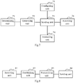
- FIG.7 it illustrates a first local controller according to an embodiment of the invention, which includes:
- the sending unit 73 is further configured to send broadcast channel configuration information to the first small base station, so that the first small base station issues common control signaling according to the broadcast channel configuration information.
- the first local controller further includes:
- the first local controller further includes:
- the first local controller further includes:
- the first local controller further includes:
- the sending unit 73 is further configured, when the user equipment transmitting the user data is switched from the first small base station to a second small base station hosted by the first local controller and the first local gateway, to send first data forwarding control signaling to the first small base station, so that when there is no direct data channel established between the first small base station and the second small base station, to forward first forwarded data to the first local gateway, so that the first local gateway forwards the first forwarded data to the second small base station, and when there is a direct data channel established between the first small base station and the second small base station, to forward first forwarded data to the second small base station over the direct data channel; and when the user equipment transmitting the user data is switched from the first small base station to a third small base station hosted by a second local controller and a second local gateway, to send second data forwarding control signaling to the first small base station, so that when there is no direct data channel established between the first small base station and the third small base station, to forward first forwarded data to the first local gateway, so that the first local gateway
- the sending unit 73 is further configured, when the user equipment transmitting the user data is switched from the first small base station to a third small base station hosted by a second local controller and a second local gateway, to send third data forwarding control signaling to the first local gateway, so that the first local gateway forwards second forwarded data to the second local gateway, and the second local gateway forwards the second forwarded data to the third small base station; Where the second forwarded data are determined by the first local gateway according to a transmission mode of the user data; and The second forwarded data include at least non-transmitted user data buffered in the first local gateway.
- FIG.8 it illustrates a first small base station according to an embodiment of the invention, which is hosted by a first local controller, and which includes:
- the first small base station is hosted by a first local gateway; and
- the establishing unit 82 is configured to establish a data transmission channel with the Internet upon determining that user data are to be transmitted directly over the Internet, according to the received data bearer configuration information; to establish a data transmission channel with the first local gateway upon determining that the first local gateway participates in transmission of user data, according to the received data bearer configuration information.
- the receiving unit 81 is further configured to receive broadcast channel configuration information sent by the first local controller; and
- the first small base station further includes:
- a sending unit 84 is configured to issue common control signaling according to the broadcast channel configuration information, so that the user equipment covered by the first small base station resides on the first small base station according to the common control signaling.
- the receiving unit 81 is further configured to receive control signaling, including small base station configuration information, sent by the first local controller, and to provide the user equipment with a data transmission service according to the small base station configuration information, where the small base station configuration information is obtained by the first local controller as a result of interacting with a macro base station; and the user equipment is located in an intersection of a coverage area by the macro base station, and a coverage area by the first small base station, and resides on the macro base station when the user equipment is idle.
- control signaling including small base station configuration information, sent by the first local controller
- the user equipment with a data transmission service according to the small base station configuration information, where the small base station configuration information is obtained by the first local controller as a result of interacting with a macro base station; and the user equipment is located in an intersection of a coverage area by the macro base station, and a coverage area by the first small base station, and resides on the macro base station when the user equipment is idle.
- the data bearer configuration information includes protocol stack configuration information of the first small base station.
- the receiving unit 81 is further configured to process the user data according to the received protocol stack configuration information before the transmitting unit transmits the user data over the established data transmission channel; and
- the transmitting unit 83 is configured to transmit the processed user data over the data transmission channel established between the first small base station and the first local gateway; Where the protocol stack configuration information of the first small base station is configured for the first small base station by the first local controller according to a network condition, and the performance of a backhaul link between the first small base station and the first local gateway; and
- the protocol stack configuration information is configured in any one of the following modes:
- the first small base station further includes:
- the first small base station further includes:
- the first small base station further includes a data forwarding unit (not illustrated) configured, when the user equipment transmitting the user data is switched from the first small base station to a second small base station hosted by the first local controller and a first local gateway, after the receiving unit receives first data forwarding control signaling of the first local controller, when there is a direct data channel established between the first small base station and the second small base station, to forward first forwarded data to the second small base station over the direct data channel; and when there is no direct data channel established between the first small base station and the second small base station, to forward first forwarded data to the first local gateway, so that the first local gateway forwards the first forwarded data to the second small base station; and
- the user equipment transmitting the user data is switched from the first small base station to a third small base station hosted by a second local controller and a second local gateway, after the receiving unit receives second data forwarding control signaling of the first local controller, when there is a direct data channel established between the first small base station and the third small base station, to forward first
- FIG.9 it illustrates a first local gateway according to an embodiment of the invention, which includes:
- the establishing unit 92 is configured to determine at least one first small base station to participate in transmission of user data, according to the received data bearer configuration information; and to establish the data transmission channel with the determined at least one first small base station; Where the first small base station is hosted by the first local gateway and the first local controller.
- the establishing unit 92 is further configured to establish a data transmission channel with the Internet upon determining that user data are to be transmitted directly over the Internet, according to the received data bearer configuration information; to establish a data transmission channel with a core network upon determining that the core network participates in transmission of user data, according to the received data bearer configuration information; to establish a data transmission channel with at least one second small base station upon determining that the at least one second small base station participates in transmission of user data, according to the received data bearer configuration information; to establish a data transmission channel with a second local gateway upon determining that the second local gateway participates in transmission of user data, according to the received data bearer configuration information, so that the first local gateway transmits user equipment of a first user equipment to a second user equipment through the second local gateway, and receives user data, transmitted by the second user equipment to the first user equipment, through the second local gateway; Where the second small base station is hosted by the first local gateway and the first local controller, the first user equipment is hosted by the first local gateway, and the second user user equipment
- the data bearer configuration information includes protocol stack configuration information of the respective first small base stations; and the first local gateway further includes:
- the first local gateway further includes:
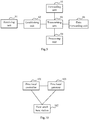
- FIG.10 it illustrates a communication system according to an embodiment of the invention, which includes a first local controller 101, a first small base station 102, and a first local gateway 103, where:
- FIG.11 it illustrates a schematic structural diagram of another first local controller according to an embodiment of the invention, which includes a processor 1100, a transceiver 1101, and a memory 1102, all of which communicate with each other via a bus interface, where:
- the processor 1100 is configured to read program in the memory 1102, and to further perform the processes of:
- the processor 1100 is configured to read the program in the memory 1102, and to further perform the process of: Sending broadcast channel configuration information to the first small base station through the transceiver 1101, so that the first small base station issues common control signaling according to the broadcast channel configuration information.
- the processor 1100 is configured to read the program in the memory 1102, and to further perform the processes of: When the user equipment residing on a macro base station is switched from an idle state to a connected state, and needs to transmit user data through the first small base station, then interacting with the macro base station through the transceiver 1101, and obtaining small base station configuration information for carrying the user data of the user equipment; and sending control signaling including the small base station configuration information to the first small base station through the transceiver 1101, so that the first small base station provides the user equipment with a data transmission service according to the small base station configuration information.
- the processor 1100 is configured to read the program in the memory 1102, and to further perform the processes of: Configuring the first small base station with protocol stack configuration information according to a network condition, and the performance of a backhaul link between the first small base station and the first local gateway, and carrying the protocol stack configuration information configured for the first small base station, in the data bearer configuration information, and sending the data bearer configuration information to the first local gateway through the transceiver 1101, so that the first local gateway processes user data received from the first small base station according to the protocol stack configuration information of the first small base station; carrying the protocol stack configuration information configured for the first small base station, in the data bearer configuration information, and sending the data bearer configuration information to the first small base station through the transceiver 1101, so that the first small base station processes user data according to the received protocol stack configuration information; and carrying the protocol stack configuration information configured for the respective first small base stations, in the data bearer configuration information, and sending the data bearer configuration information to the first local gateway through the transceiver 1101; carrying the protocol stack configuration
- the processor 1100 is configured to read the program in the memory 1102, and to further perform the processes of: Receiving a link quality measurement report through the transceiver 1101; and upon determining that the user equipment needs to be switched to at least one second small base station hosted by the first local controller, according to the received link quality measurement report, when the configuration information in the first small base station for the user equipment is not the same as configuration information in the at least one second small base station, to which the user equipment needs to be switched, for the user equipment, then sending control signaling including reconfiguration information to the user equipment through the at least one first small base station through the transceiver 1101, sending a switching instruction to the first small base station serving the user equipment through the transceiver 1101, so that the first small base station serving the user equipment stops serving the user equipment, and sending a switching instruction and the reconfiguration information to the second small base station to which the user equipment needs to be switched, so that the second small base station to which the user equipment needs to be switched starts to serve the user equipment; where the link quality measurement report includes either or both
- the processor 1100 is configured to read the program in the memory 1102, and to further perform the processes of: Receiving a link quality measurement report through the transceiver 1101; sending switching request signaling to a second local controller through the transceiver 1101 upon determining that that the user equipment needs to be switched to at least one third small base station hosted by the second local controller, according to the received link quality measurement report; receiving switching acknowledgment signaling, including configuration information configured for the user equipment, sent by the second local controller, through the transceiver 1101; and sending the received switching acknowledgment signaling including the configuration information configured for the user equipment to the user equipment through the at least one first small base station; where the link quality measurement report includes either or both of the following instances: a first instance includes a link quality measurement report measured by the user equipment for the first small base station, and a link quality measurement report measured by the user equipment for a small base station adjacent to the first small base station, and a second instance includes a link quality measurement report measured by the first small base station for the user equipment, and a link quality
- processor 1100 is configured to read the program in the memory 1102, and to further perform the processes of:
- the processor 1100 is configured to read the program in the memory 1102, and to further perform the processes of:
- the user equipment transmitting the user data is switched from the first small base station to a third small base station hosted by a second local controller and a second local gateway, then sending third data forwarding control signaling to the first local gateway through the transceiver 1101, so that the first local gateway forwards second forwarded data to the second local gateway, and the second local gateway forwards the second forwarded data to the third small base station; where the second forwarded data are determined by the first local gateway according to a transmission mode of the user data; and the second forwarded data include at least non-transmitted user data buffered in the first local gateway.
- the bus architecture can include any number of interconnected buses and bridges and particularly link together one or more processors represented by the processor 1100, and a memory represented by the memory 1102.
- the bus architecture can further link together various other circuits, e.g., peripheral devices, a voltage stabilizer, a power management circuit, etc., and all these circuits are well known in the art, so a further description thereof will be omitted in this context.
- the bus interface serves as an interface.
- the transceiver 1101 can include a number of elements including a transmitter and a receiver serving as elements configured to communicate with various other devices over a transmission medium.
- the processor 1100 is responsible for managing the bus architecture and performing other normal processes, and the memory 1102 can store data for use by the processor 1100 in performing the operations.
- FIG.12 it illustrates a schematic structural diagram of another first small base station according to an embodiment of the invention, which includes a processor 1200, a transceiver 1201, and a memory 1202, all of which communicate with each other via a bus interface, where:
- the processor 1200 is configured to read program in the memory 1202, and to further perform the processes of:
- the processor 1200 is configured to read the program in the memory 1202, and to further perform the process of: Establishing a data transmission channel with the Internet upon determining that user data are to be transmitted directly over the Internet, according to the received data bearer configuration information; establishing a data transmission channel with a first local gateway upon determining that the first local gateway participates in transmission of user data, according to the received data bearer configuration information; where the first small base station is hosted by the first local gateway.
- the processor 1200 is configured to read the program in the memory 1202, and to further perform the process of: Receiving broadcast channel configuration information sent by the first local controller through the transceiver 1201; and issuing common control signaling according to the broadcast channel configuration information, so that the user equipment covered by the first small base station resides on the first small base station according to the common control signaling.
- the processor 1200 is configured to read the program in the memory 1202, and to further perform the process of: Receiving control signaling, including small base station configuration information, sent by the first local controller, through the transceiver 1201, where the small base station configuration information is obtained by the first local controller as a result of interacting with a macro base station; and providing the user equipment with a data transmission service according to the small base station configuration information, where the user equipment is located in an intersection of a coverage area by the macro base station, and a coverage area by the first small base station, and resides on the macro base station when the user equipment is idle.
- Receiving control signaling including small base station configuration information, sent by the first local controller, through the transceiver 1201, where the small base station configuration information is obtained by the first local controller as a result of interacting with a macro base station
- the user equipment is located in an intersection of a coverage area by the macro base station, and a coverage area by the first small base station, and resides on the macro base station when the user equipment is idle.
- the data bearer configuration information includes protocol stack configuration information of the first small base station; and the processor 1200 is configured to read the program in the memory 1202, and to further perform the process of: Before transmitting the user data over the established data transmission channel, processing the user data according to the protocol stack configuration information received through the transceiver 1201; and transmitting the processed user data over the data transmission channel established with the first local gateway; where the protocol stack configuration information of the first small base station is configured for the first small base station by the first local controller according to a network condition, and the performance of a backhaul link between the first small base station and the first local gateway; and the protocol stack configuration information is configured in any one of the following modes: in a first mode, the Physical (PHY) layer, the Media Access Control (MAC) layer, the Radio Link Control (RLC) layer, and the Packet Data Convergence Protocol (PDCP) layer are located in the first local gateway; in a second mode, PHY is located in the first small base station, and MAC, RLC, and PDCP are located
- the data bearer configuration information includes protocol stack configuration information of the first small base station; and the processor 1200 is configured to read the program in the memory 1202, and to further perform the process of: Sending a link quality measurement report to the first local controller through the transceiver 1201; receiving controlling signaling including reconfiguration information, and a switching instruction, from the first local controller through the transceiver 1201; and sending the received control signaling including the reconfiguration information to the user equipment, so that the user equipment is switched to a second small base station; and the first small base station stops serving the user equipment, according to the switching instruction, where the control signaling including the reconfiguration information, and the switching instruction is issued by the first local controller, upon determining that the user equipment needs to be switched to at least one second small base station hosted by the first local controller, according to the received link quality measurement report, when the configuration information in the first small base station for the user equipment is not the same as configuration information in the at least one second small base station, to which the user equipment needs to be switched, for the user equipment; where the link quality measurement
- the data bearer configuration information includes protocol stack configuration information of the first small base station; and the processor 1200 is configured to read the program in the memory 1202, and to further perform the process of: Sending a link quality measurement report to the first local controller through the transceiver 1201; receiving switching acknowledgement signaling, including configuration information configured for the user equipment, from a second local controller through the first local controller; sending the received switching acknowledgement signaling including the reconfiguration information to the user equipment through the transceiver 1201, so that the user equipment is switched to a third small base station; and stopping serving the user equipment, according to the switching acknowledgement signaling; where the switching acknowledgement signaling is sent by the second local controller upon reception of a switching request of the first local controller to switch the user equipment to at least one third small base station hosted by the second local controller, and the third small base station is hosted by the second local controller; and the link quality measurement report includes either or both of the following instances: a first instance includes a link quality measurement report measured by the user equipment for the first small base station, and a link quality measurement
- the data bearer configuration information includes protocol stack configuration information of the first small base station; and the processor 1200 is configured to read the program in the memory 1202, and to further perform the process of: If the user equipment transmitting the user data is switched from the first small base station to a second small base station hosted by the first local controller and a first local gateway, after receiving first data forwarding control signaling of the first local controller through the transceiver 1201, if there is a direct data channel established between the first small base station and the second small base station, then forwarding first forwarded data to the second small base station over the direct data channel; and if there is no direct data channel established between the first small base station and the second small base station, then forwarding first forwarded data to the first local gateway through the transceiver 1201, so that the first local gateway forwards the first forwarded data to the second small base station; and if the user equipment transmitting the user data is switched from the first small base station to a third small base station hosted by a second local controller and a second local gateway, after receiving second data forwarding
- the bus architecture can include any number of interconnected buses and bridges and particularly link together one or more processors represented by the processor 1200, and a memory represented by the memory 1202.
- the bus architecture can further link together various other circuits, e.g., peripheral devices, a voltage stabilizer, a power management circuit, etc., and all these circuits are well known in the art, so a further description thereof will be omitted in this context.
- the bus interface serves as an interface.
- the transceiver 1201 can include a number of elements including a transmitter and a receiver serving as elements configured to communicate with various other devices over a transmission medium.
- the processor 1200 is responsible for managing the bus architecture and performing other normal processes, and the memory 1202 can store data for use by the processor 1200 in performing the operations.
- FIG.13 it illustrates a schematic structural diagram of another first local gateway according to an embodiment of the invention, which includes a processor 1300, a transceiver 1301, and a memory 1302, all of which communicate with each other via a bus interface, where:
- the processor 1300 is configured to read program in the memory 1302, and to further perform the processes of:
- the processor 1300 is configured to read the program in the memory 1302, and to further perform the process of: Determining at least one first small base station to participate in transmission of user data, according to the received data bearer configuration information; and establishing the data transmission channel with the determined at least one first small base station; where the first small base station is hosted by the first local gateway and the first local controller.
- the processor 1300 is configured to read the program in the memory 1302, and to further perform the processes of: Establishing a data transmission channel with the Internet upon determining that user data are to be transmitted directly over the Internet, according to the received data bearer configuration information; establishing a data transmission channel with a core network upon determining that the core network participates in transmission of user data, according to the received data bearer configuration information; establishing a data transmission channel with at least one second small base station upon determining that the at least one second small base station participates in transmission of user data, according to the received data bearer configuration information; establishing a data transmission channel with a second local gateway upon determining that the second local gateway participates in transmission of user data, according to the received data bearer configuration information, so that the first local gateway transmits user equipment of a first user equipment to a second user equipment through the second local gateway, and receives user data, transmitted by the second user equipment to the first user equipment, through the second local gateway; where the second small base station is hosted by the first local gateway and the first local controller, the first
- the data bearer configuration information includes protocol stack configuration information of the respective first small base stations; and the processor 1300 is configured to read the program in the memory 1302, and to further perform the processes of: Before transmitting the user data over the established data transmission channel, and after receiving the user data of the first small base station through the transceiver 1301, processing the user data according to the protocol stack configuration information of the first small base station; and transmitting the processed user data over the data transmission channel established with the at least one first small base station; where the protocol stack configuration information of the first small base station is configured for the first small base station by the first local controller according to a network condition, and the performance of a backhaul link between the first small base station and the first local gateway; and the protocol stack configuration information is configured in any one of the following modes: in a first mode, the Physical (PHY) layer, the Media Access Control (MAC) layer, the Radio Link Control (RLC) layer, and the Packet Data Convergence Protocol (PDCP) layer are located in the first local gateway; in a second mode, PHY
- the data bearer configuration information includes protocol stack configuration information of the respective first small base stations; and the processor 1300 is configured to read the program in the memory 1302, and to further perform the processes of: When the user equipment transmitting the user data is switched from the first small base station to a second small base station hosted by the first local controller and the first local gateway, then forwarding first forwarded data forwarded by the first small base station to the second small base station through the transceiver 1301; and when the user equipment transmitting the user data is switched from the first small base station to a third small base station hosted by a second local controller and a second local gateway, then forwarding first forwarded data forwarded by the first small base station to the second local gateway through the transceiver 1301, so that the second local gateway sends the received first forwarded data to the third small base station; where the first forwarded data are determined by the first small base station according to a transmission mode of the user data; and the first forwarded data include non-transmitted user data buffered in the first small base station, or non-transmitted user data
- the processor 1300 is configured to read the program in the memory 1302, and to further perform the processes of: When the user equipment transmitting the user data is switched from the first small base station to a third small base station hosted by a second local controller and a second local gateway, then receiving third data forwarded control signaling from the first local controller through the transceiver 1301; and forwarding second forwarded data to the second local gateway through the transceiver 1301, so that the second local gateway sends the received second forwarded data to the third small base station, where the second forwarded data are determined by the first local gateway according to a transmission mode of the user data; and the second forwarded data includes at least non-transmitted user data buffered in the first local gateway.
- the bus architecture can include any number of interconnected buses and bridges and particularly link together one or more processors represented by the processor 1300, and a memory represented by the memory 1302.
- the bus architecture can further link together various other circuits, e.g., peripheral devices, a voltage stabilizer, a power management circuit, etc., and all these circuits are well known in the art, so a further description thereof will be omitted in this context.
- the bus interface serves as an interface.
- the transceiver 1301 can include a number of elements including a transmitter and a receiver serving as elements configured to communicate with various other devices over a transmission medium.
- the processor 1300 is responsible for managing the bus architecture and performing other normal processes, and the memory 1302 can store data for use by the processor 1300 in performing the operations.
- the embodiments of the invention can be embodied as a method, a system or a computer program product, even if not explicitly claimed in the claims. Therefore the invention can be embodied in the form of an all-hardware embodiment, an all-software embodiment or an embodiment of software and hardware in combination. Furthermore the invention can be embodied in the form of a computer program product embodied in one or more computer useable storage mediums (including but not limited to a disk memory, an optical memory, etc.) in which computer useable program codes are contained.
- These computer program instructions can also be stored into a computer readable memory capable of directing the computer or the other programmable data processing device to operate in a specific manner so that the instructions stored in the computer readable memory create an article of manufacture including instruction means which perform the functions specified in the flow(s) of the flow chart and/or the block(s) of the block diagram.
- These computer program instructions can also be loaded onto the computer or the other programmable data processing device so that a series of operational steps are performed on the computer or the other programmable data processing device to create a computer implemented process so that the instructions executed on the computer or the other programmable device provide steps for performing the functions specified in the flow(s) of the flow chart and/or the block(s) of the block diagram.
Landscapes
- Engineering & Computer Science (AREA)
- Computer Networks & Wireless Communication (AREA)
- Signal Processing (AREA)
- Databases & Information Systems (AREA)
- Computer Security & Cryptography (AREA)
- Mobile Radio Communication Systems (AREA)
Claims (13)
- Procédé de communication, comprenant :la détermination, par un premier dispositif de commande local (101), qu'il y a un équipement utilisateur pour lequel une porteuse de données doit être établie ;la génération, par le premier dispositif de commande local (101), d'informations de configuration de porteuse de données pour transmettre les données d'utilisateur ; etl'envoi, par le premier dispositif de commande local (101), des informations de configuration de porteuse de données à une première passerelle locale (103) et/ou au moins une première petite station de base (102), de sorte qu'une entité d'élément de réseau recevant les informations de configuration de porteuse de données établisse un canal de transmission de données selon les informations de configuration de porteuse de données, dans lequel l'équipement utilisateur est attribué au premier dispositif de commande local (101) et à la première passerelle locale (103), et la première petite station de base (102) dessert l'équipement utilisateur ;le procédé comprenant en outre : la configuration, par le premier dispositif de commande local (101), de la première petite station de base (102) avec des informations de configuration de pile de protocoles selon un état de réseau, et une performance d'une liaison terrestre entre la première petite station de base (102) et la première passerelle locale (103) ; etl'envoi, par le premier dispositif de commande local (101), des informations de configuration de porteuse de données à la première passerelle locale (103) comprend :l'acheminement, par le premier dispositif de commande local (101), des informations de configuration de pile de protocoles configurées pour la première petite station de base (102), dans les informations de configuration de porteuse de données, et l'envoi des informations de configuration de porteuse de données à la première passerelle locale (103), de sorte que la première passerelle locale (103) traite des données d'utilisateur reçues en provenance de la première petite station de base (102) selon les informations de configuration de pile de protocoles de la première petite station de base (102) ; oul'envoi, par le premier dispositif de commande local (101), des informations de configuration de porteuse de données à l'au moins une première petite station de base (102) comprend :l'acheminement, par le premier dispositif de commande local (101), des informations de configuration de pile de protocoles configurées pour la première petite station de base (102), dans les informations de configuration de porteuse de données, et l'envoi des informations de configuration de porteuse de données à la première petite station de base (102), de sorte que la première petite station de base (102) traite des données d'utilisateur selon les informations de configuration de pile de protocoles reçues ; oul'envoi, par le premier dispositif de commande local (101), des informations de configuration de porteuse de données à la première passerelle locale (103) et à l'au moins une première petite station de base (102) comprend :l'acheminement, par le premier dispositif de commande local (101), des informations de configuration de pile de protocoles configurées pour les premières petites stations de base (102) respectives, dans les informations de configuration de porteuse de données, et l'envoi des informations de configuration de porteuse de données à la première passerelle locale (103), et l'acheminement des informations de configuration de pile de protocoles configurées pour les premières petites stations de base (102), dans les informations de configuration de porteuse de données, et l'envoi des informations de configuration de porteuse de données à la première petite station de base (102), de sorte que les premières petites stations de base (102) traitent des données d'utilisateur selon les informations de configuration de pile de protocoles reçues, et la première passerelle locale (103) traite des données d'utilisateur reçues en provenance des premières petites stations de base (102) selon les informations de configuration de pile de protocoles des premières petites stations de base (102) ;dans lequel les informations de configuration de pile de protocoles sont configurées selon l'un quelconque des modes suivants :dans un premier mode, une couche physique, PHY, une couche de contrôle d'accès au support, MAC, une couche de commande de liaison radio, RLC, et une couche de protocole de convergence de données par paquets, PDCP, sont situées dans la première passerelle locale (103) ;dans un deuxième mode, la couche PHY est située dans la première petite station de base (102), et les couches MAC, RLC et PDCP sont situées dans la première passerelle locale (103) ;dans un troisième mode, les couches PHY et MAC sont situées dans la première petite station de base (102), et les couches RLC et PDCP sont situées dans la première passerelle locale (103) ; etdans un quatrième mode, les couches PHY, MAC et RLC sont situées dans la première petite station de base (102), et la couche PDCP est située dans la première passerelle locale (103) ;dans lequel le premier dispositif de commande local (101) et la première passerelle locale (103) sont configurés pour servir d'ancre de plan de commande et d'ancre de plan utilisateur de la première petite station de base (102) ; à partir d'une perspective du plan de commande, la première petite station de base (102) accède à un réseau d'infrastructure par le biais du premier dispositif de commande local (101) ; à partir d'une perspective du plan utilisateur, la première petite station de base (102) accède au réseau d'infrastructure par le biais de la première passerelle locale (103), ou accède directement à Internet.
- Procédé selon la revendication 1, comprenant en outre :
l'envoi, par le premier dispositif de commande local (101), d'informations de configuration de canal de radiodiffusion à la première petite station de base (102), de sorte que la première petite station de base (102) émette une signalisation de commande commune selon les informations de configuration de canal de radiodiffusion. - Procédé selon la revendication 1, comprenant en outre :lorsque l'équipement utilisateur résidant sur une macro station de base est commuté d'un état inactif à un état connecté, et doit transmettre des données d'utilisateur par le biais de la première petite station de base (102), alors l'interaction, par le premier dispositif de commande local (101), avec la macro station de base, et l'obtention d'informations de configuration de petite station de base pour acheminer les données d'utilisateur de l'équipement utilisateur ; etl'envoi, par le premier dispositif de commande local (101), d'une signalisation de commande comprenant les informations de configuration de petite station de base à la première petite station de base (102), de sorte que la première petite station de base (102) fournisse à l'équipement utilisateur un service de transmission de données selon les informations de configuration de petite station de base.
- Procédé selon la revendication 1, comprenant en outre :la réception, par le premier dispositif de commande local (101), d'un rapport de mesure de qualité de liaison ; etlors de la détermination, par le premier dispositif de commande local (101), que l'équipement utilisateur doit être commuté à au moins une deuxième petite station de base attribuée au premier dispositif de commande local (101), selon le rapport de mesure de qualité de liaison reçu, lorsque les informations de configuration dans la première petite station de base (102) pour l'équipement utilisateur ne sont pas les mêmes que des informations de configuration dans l'au moins une deuxième petite station de base, à laquelle l'équipement utilisateur doit être commuté, pour l'équipement utilisateur, alors l'envoi d'une signalisation de commande comprenant des informations de reconfiguration à l'équipement utilisateur par le biais de l'au moins une première petite station de base (102) ; etl'envoi d'une instruction de commutation à la première petite station de base (102) desservant l'équipement utilisateur, de sorte que la première petite station de base (102) desservant l'équipement utilisateur arrête de desservir l'équipement utilisateur, et l'envoi d'une instruction de commutation et des informations de reconfiguration à la deuxième petite station de base à laquelle l'équipement utilisateur doit être commuté, de sorte que la deuxième petite station de base à laquelle l'équipement utilisateur doit être commuté commence à desservir l'équipement utilisateur ;dans lequel le rapport de mesure de qualité de liaison comprend l'une ou l'autre ou les deux des instances suivantes :une première instance comprend un rapport de mesure de qualité de liaison mesuré par un équipement utilisateur pour la première petite station de base (102), et un rapport de mesure de qualité de liaison mesuré par un équipement utilisateur pour une petite station de base adjacente à la première petite station de base (102), et une seconde instance comprend un rapport de mesure de qualité de liaison mesuré par la première petite station de base (102) pour l'équipement utilisateur, et un rapport de mesure de qualité de liaison mesuré par une petite station de base adjacente à la première petite station de base (102) pour l'équipement utilisateur ; etles informations de reconfiguration sont déterminées par le premier dispositif de commande local (101) selon les informations de configuration de l'équipement utilisateur dans la deuxième petite station de base.
- Procédé selon la revendication 1, comprenant en outre :la réception, par le premier dispositif de commande local (101), d'un rapport de mesure de qualité de liaison ;l'envoi, par le premier dispositif de commande local (101), d'une signalisation de demande de commutation à un second dispositif de commande local lors de la détermination que l'équipement utilisateur doit être commuté à au moins une troisième petite station de base attribuée au second dispositif de commande local, selon le rapport de mesure de qualité de liaison reçu ;la réception, par le premier dispositif de commande local (101), d'une signalisation d'accusé de réception de commutation, comprenant des informations de configuration configurées pour l'équipement utilisateur, envoyée par le second dispositif de commande local ; etl'envoi, par le premier dispositif de commande local (101), de la signalisation d'accusé de réception de commutation reçue comprenant les informations de configuration configurées pour l'équipement utilisateur à l'équipement utilisateur par le biais de l'au moins une première petite station de base (101) ;dans lequel le rapport de mesure de qualité de liaison comprend l'une ou l'autre ou les deux instances suivantes :une première instance comprend un rapport de mesure de qualité de liaison mesuré par l'équipement utilisateur pour la première petite station de base (102), et un rapport de mesure de qualité de liaison mesuré par l'équipement utilisateur pour une petite station de base adjacente à la première petite station de base (102), etune seconde instance comprend un rapport de mesure de qualité de liaison mesuré par la première petite station de base (102) pour l'équipement utilisateur, et une mesure de qualité de liaison mesurée par une petite station de base adjacente à la première petite station de base (102) pour l'équipement utilisateur.
- Procédé selon la revendication 1, dans lequel, lorsque l'équipement utilisateur transmettant les données d'utilisateur est commuté de la première petite station de base (102) à une deuxième petite station de base attribuée au premier dispositif de commande local (101) et à la première passerelle locale (103), alors le procédé comprend en outre :l'envoi, par le premier dispositif de commande local (101), d'une première signalisation de commande de réacheminement de données à la première petite station de base (102), de sorte que lorsqu'il n'y a pas de canal de liaison directe établi entre la première petite station de base (102) et la deuxième petite station de base, alors le réacheminement de premières données réacheminées à la première passerelle locale (103), de sorte que la première passerelle locale (103) réachemine les premières données réacheminées à la deuxième petite station de base, et lorsqu'il y a un canal de liaison directe établi entre la première petite station de base (102) et la deuxième petite station de base, alors le réacheminement de premières données réacheminées à la deuxième petite station de base sur le canal de liaison directe ; oulorsque l'équipement utilisateur transmettant les données d'utilisateur est commuté de la première petite station de base (102) à une troisième petite station de base attribuée au second dispositif de commande local et à une seconde passerelle locale, alors le procédé comprend en outre :l'envoi, par le premier dispositif de commande local (101), d'une deuxième signalisation de commande de réacheminement de données à la première petite station de base (102), de sorte que lorsqu'il n'y a pas de canal de liaison directe établi entre la première petite station de base (102) et la troisième petite station de base, alors le réacheminement de premières données réacheminées à la première passerelle locale (103), de sorte que la première passerelle locale (103) réachemine les premières données réacheminées à la troisième petite station de base par le biais de la seconde passerelle locale, et lorsqu'il y a un canal de liaison directe établi entre la première petite station de base (102) etla troisième petite station de base, alors le réacheminement de premières données réacheminées à la troisième petite station de base sur le canal de liaison directe ;dans lequel les premières données réacheminées sont déterminées par la première petite station de base (102) selon un mode de transmission des données d'utilisateur ;et
les premières données réacheminées comprennent des données d'utilisateur non transmises mises en mémoire tampon dans la première petite station de base (102), ou des données d'utilisateur non transmises, et des données d'utilisateur transmises pour lesquelles aucun message d'accusé de réception n'est reçu, mises en mémoire tampon dans la première petite station de base (102). - Procédé selon la revendication 1, dans lequel, lorsque l'équipement utilisateur transmettant les données d'utilisateur est commuté de la première petite station de base (102) à une troisième petite station de base attribuée à un second dispositif de commande local et à une seconde passerelle locale, alors le procédé comprend en outre :l'envoi, par le premier dispositif de commande local (101), d'une troisième signalisation de commande de réacheminement de données à la première passerelle locale (103), de sorte que la première passerelle locale (103) réachemine des secondes données réacheminées à la seconde passerelle locale, et la seconde passerelle locale réachemine les secondes données réacheminées à la troisième petite station de base ;dans lequel les secondes données réacheminées sont déterminées par la première passerelle locale (103) selon un mode de transmission des données d'utilisateur ; etles secondes données réacheminées comprennent au moins des données d'utilisateur non transmises mises en mémoire tampon dans la première passerelle locale (103).
- Procédé de communication, comprenant :la réception, par une première petite station de base (102), d'informations de configuration de porteuse de données pour transmettre des données d'utilisateur, en provenance d'un premier dispositif de commande local (101) ;l'établissement, par la première petite station de base (102), d'un canal de transmission de données selon les informations de configuration de porteuse de données reçues ; etla transmission, par la première petite station de base (102), des données d'utilisateur sur le canal de transmission de données établi ;dans lequel la première petite station de base (102) est attribuée au premier dispositif de commande local (101) ;dans lequel l'établissement, par la première petite station de base (102), du canal de transmission de données selon les informations de configuration de porteuse de données reçues comprend :l'établissement, par la première petite station de base (102), d'un canal de transmission de données avec Internet lors de la détermination que des données d'utilisateur doivent être transmises directement par Internet, selon les informations de configuration de porteuse de données reçues ;l'établissement, par la première petite station de base (102), d'un canal de transmission de données avec une première passerelle locale (103) lors de la détermination que la première passerelle locale (103) participe à la transmission de données d'utilisateur, selon les informations de configuration de porteuse de données reçues ;dans lequel la première petite station de base (102) est attribuée à la première passerelle locale (103) ;dans lequel les informations de configuration de porteuse de données comprennent des informations de configuration de pile de protocoles de la première petite station de base (102) ; et avant que la première petite station de base (102) transmette les données d'utilisateur sur le canal de transmission de données établi, le procédé comprend en outre :le traitement, par la première petite station de base (102), des données d'utilisateur selon les informations de configuration de pile de protocoles reçues ; etla transmission, par la première petite station de base (102), des données d'utilisateur sur le canal de transmission de données établi comprend :la transmission, par la première petite station de base (102), des données d'utilisateur traitées sur le canal de transmission de données établi entre la première petite station de base (102) et la première passerelle locale (103) ;dans lequel les informations de configuration de pile de protocoles de la première petite station de base (102) sont configurées pour la première petite station de base (102) par le premier dispositif de commande local (101) selon un état de réseau, et une performance d'une liaison terrestre entre la première petite station de base (102) et la première passerelle locale (103) ;et
les informations de configuration de pile de protocoles sont configurées selon l'un quelconque des modes suivants :dans un premier mode, une couche physique, PHY, une couche de contrôle d'accès au support, MAC, une couche de commande de liaison radio, RLC, et une couche de protocole de convergence de données par paquets, PDCP, sont situées dans la première passerelle locale (103) ;dans un deuxième mode, la couche PHY est située dans la première petite station de base (102), et les couches MAC, RLC et PDCP sont situées dans la première passerelle locale (103) ;dans un troisième mode, les couches PHY et MAC sont situées dans la première petite station de base (102), et les couches RLC et PDCP sont situées dans la première passerelle locale (103) ; etdans un quatrième mode, les couches PHY, MAC et RLC sont situées dans la première petite station de base (102), et la couche PDCP est située dans la première passerelle locale (103) ;dans lequel le premier dispositif de commande local (101) et la première passerelle locale (103) sont configurés pour servir d'ancre de plan de commande et d'ancre de plan utilisateur de la première petite station de base (102) ; à partir d'une perspective du plan de commande, la première petite station de base (102) accède à un réseau d'infrastructure par le biais du premier dispositif de commande local (101) ; à partir d'une perspective du plan utilisateur, la première petite station de base (102) accède au réseau d'infrastructure par le biais de la première passerelle locale (103), ou accède directement à Internet. - Procédé selon la revendication 8, comprenant en outre :la réception, par la première petite station de base (102), d'informations de configuration de canal de radiodiffusion envoyées par le premier dispositif de commande local (101) ; etl'émission, par la première petite station de base (102), d'une signalisation de commande commune selon les informations de configuration de canal de radiodiffusion, de sorte que l'équipement utilisateur couvert par la première petite station de base (102) réside sur la première petite station de base (102) selon la signalisation de commande commune.
- Procédé selon la revendication 8, comprenant en outre :la réception, par la première petite station de base (102), d'une signalisation de commande, comprenant des informations de configuration de petite station de base, envoyée par le premier dispositif de commande local (101), dans lequel les informations de configuration de petite station de base sont obtenues par le premier dispositif de commande local (101) suite à une interaction avec une macro station de base ; etla fourniture, par la première petite station de base (102), à l'équipement utilisateur d'un service de transmission de données selon les informations de configuration de petite station de base, dans lequel l'équipement utilisateur est situé à une intersection d'une zone de couverture par la macro station de base, et d'une zone de couverture par la première petite station de base (102), et réside sur la macro station de base lorsque l'équipement utilisateur est inactif.
- Procédé selon la revendication 8, comprenant en outre :l'envoi, par la première petite station de base (102), d'un rapport de mesure de qualité de liaison au premier dispositif de commande local (101) ;la réception, par la première petite station de base (102), d'une signalisation de commande comprenant des informations de reconfiguration, et une instruction de commutation, en provenance du premier dispositif de commande local (101) ;l'envoi, par la première petite station de base (102), de la signalisation de commande reçue comprenant les informations de reconfiguration à l'équipement utilisateur, de sorte que l'équipement utilisateur soit commuté à une deuxième petite station de base ; etl'arrêt, par la première petite station de base (102), de la desserte de l'équipement utilisateur, selon l'instruction de commutation ;dans lequel la signalisation de commande comprend les informations de reconfiguration, et l'instruction de commutation est émise par le premier dispositif de commande local (101), lors de la détermination que l'équipement utilisateur doit être commuté à au moins une deuxième petite station de base attribuée au premier dispositif de commande local (101), selon le rapport de mesure de qualité de liaison reçu, lorsque les informations de configuration dans la première petite station de base (102) pour l'équipement utilisateur ne sont pas les mêmes que des informations de configuration dans l'au moins une deuxième petite station de base, à laquelle l'équipement utilisateur doit être commuté, pour l'équipement utilisateur ;le rapport de mesure de qualité de liaison comprend l'une ou l'autre ou les deux instances suivantes :une première instance comprend un rapport de mesure de qualité de liaison mesuré par l'équipement utilisateur pour la première petite station de base (102), et un rapport de mesure de qualité de liaison mesuré par l'équipement utilisateur pour une petite station de base adjacente à la première petite station de base (102), et une seconde instance comprend un rapport de mesure de qualité de liaison mesuré par la première petite station de base (102) pour l'équipement utilisateur, et un rapport de mesure de qualité de liaison mesuré par une petite station de base adjacente à la première petite station de base (102) pour l'équipement utilisateur ; etles informations de reconfiguration sont déterminées par le premier dispositif de commande local (101) selon des informations de configuration de l'équipement utilisateur dans une troisième petite station de base.
- Procédé selon la revendication 8, comprenant en outre :l'envoi, par la première petite station de base (102), d'un rapport de mesure de qualité de liaison au premier dispositif de commande local (101) ;la réception, par la première petite station de base (102), d'une signalisation d'accusé de réception de commutation, comprenant des informations de configuration configurées pour l'équipement utilisateur, en provenance d'un second dispositif de commande local par le biais du premier dispositif de commande local (101) ;l'envoi, par la première petite station de base (102), de la signalisation d'accusé de réception de commutation reçue comprenant les informations de reconfiguration à l'équipement utilisateur, de sorte que l'équipement utilisateur soit commuté à une troisième petite station de base ; etl'arrêt, par la première petite station de base (102), de la desserte de l'équipement utilisateur, selon la signalisation d'accusé de réception de commutation ;dans lequel la signalisation d'accusé de réception de commutation est envoyée par le second dispositif de commande local lors de la réception d'une demande de commutation du premier dispositif de commande local (101) pour commuter l'équipement utilisateur à au moins une troisième petite station de base, et la troisième petite station de base est attribuée au second dispositif de commande local ; etle rapport de mesure de qualité de liaison comprend l'une ou l'autre ou les deux instances suivantes :une première instance comprend un rapport de mesure de qualité de liaison mesuré par l'équipement utilisateur pour la première petite station de base (102), et un rapport de mesure de qualité de liaison mesuré par l'équipement utilisateur pour une petite station de base adjacente à la première petite station de base (102), etune seconde instance comprend un rapport de mesure de qualité de liaison mesuré par la première petite station de base (102) pour l'équipement utilisateur, et un rapport de mesure de qualité de liaison mesuré par une petite station de base adjacente à la première petite station de base (102) pour l'équipement utilisateur.
- Procédé selon la revendication 8, dans lequel, lorsque l'équipement utilisateur transmettant les données d'utilisateur est commuté de la première petite station de base (102) à une deuxième petite station de base attribuée au premier dispositif de commande local (101) et à une première passerelle locale (103), alors le procédé comprend en outre :après que la première petite station de base (102) reçoit une première signalisation de commande de réacheminement de données du premier dispositif de commande local (101), lorsqu'il y a un canal de liaison directe établi entre la première petite station de base (102) et la deuxième petite station de base, alors le réacheminement de premières données réacheminées à la deuxième petite station de base sur le canal de liaison directe ; etlorsqu'il n'y a pas de canal de liaison directe établi entre la première petite station de base (102) et la deuxième petite station de base, alors le réacheminement de premières données réacheminées à la première passerelle locale (103), de sorte que la première passerelle locale (103) réachemine les premières données réacheminées à la deuxième petite station de base ;lorsque l'équipement utilisateur transmettant les données d'utilisateur est commuté de la première petite station de base (102) à une troisième petite station de base attribuée à un second dispositif de commande local et à une seconde passerelle locale, alors le procédé comprend en outre :après que la première petite station de base (102) reçoit une deuxième signalisation de commande de réacheminement de données du premier dispositif de commande local (101), lorsqu'il y a un canal de liaison directe établi entre la première petite station de base (102) et la troisième petite station de base, alors le réacheminement de premières données réacheminées à la troisième petite station de base sur le canal de liaison directe ; etlorsqu'il n'y a pas de canal de liaison directe établi entre la première petite station de base (102) et la troisième petite station de base, alors le réacheminement des premières données réacheminées à la première passerelle locale (103), de sorte que la première passerelle locale (103) réachemine les premières données réacheminées à la troisième petite station de base par le biais de la seconde passerelle locale ;dans lequel les premières données réacheminées sont déterminées par la première petite station de base (102) selon un mode de transmission des données d'utilisateur ;et
les premières données réacheminées comprennent des données d'utilisateur non transmises mises en mémoire tampon dans la première petite station de base (102), ou des données d'utilisateur non transmises, et des données d'utilisateur transmises pour lesquelles aucun message d'accusé de réception n'est reçu, mises en mémoire tampon dans la première petite station de base (102).
Applications Claiming Priority (2)
| Application Number | Priority Date | Filing Date | Title |
|---|---|---|---|
| CN201410536365.6A CN105578513B (zh) | 2014-10-11 | 2014-10-11 | 一种通信方法、设备及系统 |
| PCT/CN2015/091058 WO2016054984A2 (fr) | 2014-10-11 | 2015-09-29 | Procédé, dispositif et système de communication |
Publications (3)
| Publication Number | Publication Date |
|---|---|
| EP3206458A2 EP3206458A2 (fr) | 2017-08-16 |
| EP3206458A4 EP3206458A4 (fr) | 2017-09-27 |
| EP3206458B1 true EP3206458B1 (fr) | 2019-08-21 |
Family
ID=55653908
Family Applications (1)
| Application Number | Title | Priority Date | Filing Date |
|---|---|---|---|
| EP15848978.1A Active EP3206458B1 (fr) | 2014-10-11 | 2015-09-29 | Procédé, dispositif et système de communication |
Country Status (4)
| Country | Link |
|---|---|
| US (1) | US10383049B2 (fr) |
| EP (1) | EP3206458B1 (fr) |
| CN (1) | CN105578513B (fr) |
| WO (1) | WO2016054984A2 (fr) |
Families Citing this family (10)
| Publication number | Priority date | Publication date | Assignee | Title |
|---|---|---|---|---|
| WO2016068765A1 (fr) * | 2014-10-30 | 2016-05-06 | Telefonaktiebolaget L M Ericsson (Publ) | Premier nœud et procédés associés pour commander une puissance de transmission d'un deuxième nœud |
| CN108282868B (zh) * | 2017-01-05 | 2023-07-18 | 中兴通讯股份有限公司 | 控制信令配置方法及装置 |
| CN107404749B (zh) * | 2017-06-30 | 2020-05-08 | 上海华为技术有限公司 | 一种通信连接方法及基站 |
| CN107181827A (zh) * | 2017-07-28 | 2017-09-19 | 湖南中车时代通信信号有限公司 | 一种用于铁路网络的通信控制的方法及网关 |
| US11057791B2 (en) | 2018-10-30 | 2021-07-06 | At&T Intellectual Property I, L.P. | Configuration and reconfiguration of aggregated backhaul bearers in a multi-hop integrated access backhaul network for 5G or other next generation network |
| US10958511B2 (en) | 2018-11-01 | 2021-03-23 | At&T Intellectual Property I, L.P. | Integrated access backhaul network architecture to support bearer aggregation for 5G or other next generation network |
| CN111404633B (zh) * | 2019-01-03 | 2021-10-26 | 华为技术有限公司 | 一种选择传输模式的方法及设备 |
| US11102835B1 (en) * | 2020-04-07 | 2021-08-24 | Sprint Spectrum L.P. | Use of MU-MIMO grouping efficiency as a basis to control configuration of dual-connectivity service |
| CN112311649B (zh) * | 2020-11-03 | 2022-11-22 | 优刻得科技股份有限公司 | Pe设备的动态灾备方法、系统、设备、介质和混合云系统 |
| CN113068228B (zh) * | 2021-03-18 | 2022-11-15 | 几维通信技术(深圳)有限公司 | 基于融合网关的远洋移动通信方法 |
Family Cites Families (8)
| Publication number | Priority date | Publication date | Assignee | Title |
|---|---|---|---|---|
| CN101690381A (zh) * | 2007-04-16 | 2010-03-31 | 艾利森电话股份有限公司 | 用于在网络之间交换小区信息的方法 |
| CN101188801B (zh) * | 2007-06-20 | 2010-09-01 | 中兴通讯股份有限公司 | 公共状态下配置传输承载的方法 |
| EP2512171B1 (fr) * | 2011-04-14 | 2014-08-13 | Alcatel Lucent | Procédé de gestion de l'état de micro-stations de base en suivant les variations des exigences de trafic et dispositif contrôleur correspondant |
| JP5785517B2 (ja) * | 2012-04-19 | 2015-09-30 | 株式会社Nttドコモ | 無線通信システムおよびネットワーク |
| CN104429111B (zh) * | 2012-07-20 | 2019-02-19 | 华为技术有限公司 | 具有本地集群、中央控制器、微基站和宏基站的网络系统 |
| CN111225386B (zh) * | 2012-12-20 | 2023-07-18 | 北京三星通信技术研究有限公司 | 小小区通信的方法、系统及其设备 |
| MX353577B (es) * | 2012-12-28 | 2018-01-19 | Nec Corp | Sistema de radiocomunicación, estación base, estación móvil, método de control de comunicación, y medio legible por computadora. |
| WO2015115749A1 (fr) * | 2014-01-31 | 2015-08-06 | Lg Electronics Inc. | Procédé de notification pour système communication d2d et dispositif associé |
-
2014
- 2014-10-11 CN CN201410536365.6A patent/CN105578513B/zh active Active
-
2015
- 2015-09-29 US US15/518,238 patent/US10383049B2/en active Active
- 2015-09-29 EP EP15848978.1A patent/EP3206458B1/fr active Active
- 2015-09-29 WO PCT/CN2015/091058 patent/WO2016054984A2/fr not_active Ceased
Non-Patent Citations (1)
| Title |
|---|
| None * |
Also Published As
| Publication number | Publication date |
|---|---|
| US20170311251A1 (en) | 2017-10-26 |
| EP3206458A4 (fr) | 2017-09-27 |
| EP3206458A2 (fr) | 2017-08-16 |
| WO2016054984A3 (fr) | 2016-06-02 |
| CN105578513A (zh) | 2016-05-11 |
| US10383049B2 (en) | 2019-08-13 |
| WO2016054984A2 (fr) | 2016-04-14 |
| CN105578513B (zh) | 2019-02-12 |
Similar Documents
| Publication | Publication Date | Title |
|---|---|---|
| US10383049B2 (en) | Communications method, device, and system | |
| CN115245039B (zh) | 对侧链路中继服务的服务质量支持 | |
| US11546811B2 (en) | Method for establishing a fronthaul interface, method for performing access for a UE, method and apparatus for performing a handover for a UE, data forwarding method, user equipment and base station | |
| RU2713442C1 (ru) | Система и способ переключения сот | |
| JP6348517B2 (ja) | ロングタームエボリューション無線アクセスネットワーク | |
| WO2020030165A1 (fr) | Procédé et appareil de transmission de données, et procédé et appareil de commutation de service | |
| WO2022082601A1 (fr) | Procédé et appareil de mobilité entre donneurs | |
| JP2012525720A (ja) | モバイルネットワーク、無線アクセスノード、リレー装置を含むシステム、およびその方法 | |
| TWI568282B (zh) | Configuration method and device for working mode of data forwarding device | |
| US9668244B2 (en) | Radio resource management method, macro base station, and low-power node | |
| EP2921025A1 (fr) | Procédé de communication de dispositif à dispositif et procédé de commande correspondant | |
| US12063591B2 (en) | Method and apparatus for relay utilizing sidelink in wireless communication system | |
| CN116419339A (zh) | 通信方法、装置及系统 | |
| US20240388975A1 (en) | Method and apparatus for inter-central unit (cu) handover of integrated access and backhaul (iab) node in wireless communication system | |
| US20240121686A1 (en) | Handover technique for time-sensitive networking | |
| US11051213B2 (en) | Core network node and method therein for obtaining a decision of a CN/RAN endpoint pair for user plane session in a radio communications network | |
| CN115004778B (zh) | 辅小区-用户设备切换 | |
| Zhou et al. | Multipath tcp for user cooperation in wireless networks | |
| WO2023242781A1 (fr) | Procédés et nœuds pour mobilité de nœud iab avec cu d'ancrage | |
| WO2016188388A1 (fr) | Procédé pour mettre en œuvre une gestion de qualité de service | |
| CN119155768A (zh) | 通信方法及相关装置 | |
| CN119967501A (zh) | 一种终端移动性管理方法、装置、电子设备和计算机程序产品 |
Legal Events
| Date | Code | Title | Description |
|---|---|---|---|
| STAA | Information on the status of an ep patent application or granted ep patent |
Free format text: STATUS: THE INTERNATIONAL PUBLICATION HAS BEEN MADE |
|
| PUAI | Public reference made under article 153(3) epc to a published international application that has entered the european phase |
Free format text: ORIGINAL CODE: 0009012 |
|
| STAA | Information on the status of an ep patent application or granted ep patent |
Free format text: STATUS: REQUEST FOR EXAMINATION WAS MADE |
|
| 17P | Request for examination filed |
Effective date: 20170504 |
|
| AK | Designated contracting states |
Kind code of ref document: A2 Designated state(s): AL AT BE BG CH CY CZ DE DK EE ES FI FR GB GR HR HU IE IS IT LI LT LU LV MC MK MT NL NO PL PT RO RS SE SI SK SM TR |
|
| AX | Request for extension of the european patent |
Extension state: BA ME |
|
| A4 | Supplementary search report drawn up and despatched |
Effective date: 20170825 |
|
| RIC1 | Information provided on ipc code assigned before grant |
Ipc: H04W 88/16 20090101ALI20170821BHEP Ipc: H04W 88/12 20090101AFI20170821BHEP Ipc: H04W 88/08 20090101ALI20170821BHEP |
|
| DAV | Request for validation of the european patent (deleted) | ||
| DAX | Request for extension of the european patent (deleted) | ||
| STAA | Information on the status of an ep patent application or granted ep patent |
Free format text: STATUS: EXAMINATION IS IN PROGRESS |
|
| 17Q | First examination report despatched |
Effective date: 20181102 |
|
| GRAP | Despatch of communication of intention to grant a patent |
Free format text: ORIGINAL CODE: EPIDOSNIGR1 |
|
| STAA | Information on the status of an ep patent application or granted ep patent |
Free format text: STATUS: GRANT OF PATENT IS INTENDED |
|
| INTG | Intention to grant announced |
Effective date: 20190507 |
|
| GRAS | Grant fee paid |
Free format text: ORIGINAL CODE: EPIDOSNIGR3 |
|
| GRAA | (expected) grant |
Free format text: ORIGINAL CODE: 0009210 |
|
| STAA | Information on the status of an ep patent application or granted ep patent |
Free format text: STATUS: THE PATENT HAS BEEN GRANTED |
|
| AK | Designated contracting states |
Kind code of ref document: B1 Designated state(s): AL AT BE BG CH CY CZ DE DK EE ES FI FR GB GR HR HU IE IS IT LI LT LU LV MC MK MT NL NO PL PT RO RS SE SI SK SM TR |
|
| REG | Reference to a national code |
Ref country code: GB Ref legal event code: FG4D |
|
| REG | Reference to a national code |
Ref country code: CH Ref legal event code: EP |
|
| REG | Reference to a national code |
Ref country code: DE Ref legal event code: R096 Ref document number: 602015036459 Country of ref document: DE |
|
| REG | Reference to a national code |
Ref country code: AT Ref legal event code: REF Ref document number: 1171218 Country of ref document: AT Kind code of ref document: T Effective date: 20190915 |
|
| REG | Reference to a national code |
Ref country code: IE Ref legal event code: FG4D |
|
| REG | Reference to a national code |
Ref country code: LT Ref legal event code: MG4D |
|
| REG | Reference to a national code |
Ref country code: NL Ref legal event code: MP Effective date: 20190821 |
|
| PG25 | Lapsed in a contracting state [announced via postgrant information from national office to epo] |
Ref country code: NO Free format text: LAPSE BECAUSE OF FAILURE TO SUBMIT A TRANSLATION OF THE DESCRIPTION OR TO PAY THE FEE WITHIN THE PRESCRIBED TIME-LIMIT Effective date: 20191121 Ref country code: NL Free format text: LAPSE BECAUSE OF FAILURE TO SUBMIT A TRANSLATION OF THE DESCRIPTION OR TO PAY THE FEE WITHIN THE PRESCRIBED TIME-LIMIT Effective date: 20190821 Ref country code: LT Free format text: LAPSE BECAUSE OF FAILURE TO SUBMIT A TRANSLATION OF THE DESCRIPTION OR TO PAY THE FEE WITHIN THE PRESCRIBED TIME-LIMIT Effective date: 20190821 Ref country code: BG Free format text: LAPSE BECAUSE OF FAILURE TO SUBMIT A TRANSLATION OF THE DESCRIPTION OR TO PAY THE FEE WITHIN THE PRESCRIBED TIME-LIMIT Effective date: 20191121 Ref country code: SE Free format text: LAPSE BECAUSE OF FAILURE TO SUBMIT A TRANSLATION OF THE DESCRIPTION OR TO PAY THE FEE WITHIN THE PRESCRIBED TIME-LIMIT Effective date: 20190821 Ref country code: PT Free format text: LAPSE BECAUSE OF FAILURE TO SUBMIT A TRANSLATION OF THE DESCRIPTION OR TO PAY THE FEE WITHIN THE PRESCRIBED TIME-LIMIT Effective date: 20191223 Ref country code: HR Free format text: LAPSE BECAUSE OF FAILURE TO SUBMIT A TRANSLATION OF THE DESCRIPTION OR TO PAY THE FEE WITHIN THE PRESCRIBED TIME-LIMIT Effective date: 20190821 Ref country code: FI Free format text: LAPSE BECAUSE OF FAILURE TO SUBMIT A TRANSLATION OF THE DESCRIPTION OR TO PAY THE FEE WITHIN THE PRESCRIBED TIME-LIMIT Effective date: 20190821 |
|
| PG25 | Lapsed in a contracting state [announced via postgrant information from national office to epo] |
Ref country code: RS Free format text: LAPSE BECAUSE OF FAILURE TO SUBMIT A TRANSLATION OF THE DESCRIPTION OR TO PAY THE FEE WITHIN THE PRESCRIBED TIME-LIMIT Effective date: 20190821 Ref country code: AL Free format text: LAPSE BECAUSE OF FAILURE TO SUBMIT A TRANSLATION OF THE DESCRIPTION OR TO PAY THE FEE WITHIN THE PRESCRIBED TIME-LIMIT Effective date: 20190821 Ref country code: IS Free format text: LAPSE BECAUSE OF FAILURE TO SUBMIT A TRANSLATION OF THE DESCRIPTION OR TO PAY THE FEE WITHIN THE PRESCRIBED TIME-LIMIT Effective date: 20191221 Ref country code: GR Free format text: LAPSE BECAUSE OF FAILURE TO SUBMIT A TRANSLATION OF THE DESCRIPTION OR TO PAY THE FEE WITHIN THE PRESCRIBED TIME-LIMIT Effective date: 20191122 Ref country code: LV Free format text: LAPSE BECAUSE OF FAILURE TO SUBMIT A TRANSLATION OF THE DESCRIPTION OR TO PAY THE FEE WITHIN THE PRESCRIBED TIME-LIMIT Effective date: 20190821 Ref country code: ES Free format text: LAPSE BECAUSE OF FAILURE TO SUBMIT A TRANSLATION OF THE DESCRIPTION OR TO PAY THE FEE WITHIN THE PRESCRIBED TIME-LIMIT Effective date: 20190821 |
|
| REG | Reference to a national code |
Ref country code: AT Ref legal event code: MK05 Ref document number: 1171218 Country of ref document: AT Kind code of ref document: T Effective date: 20190821 |
|
| PG25 | Lapsed in a contracting state [announced via postgrant information from national office to epo] |
Ref country code: TR Free format text: LAPSE BECAUSE OF FAILURE TO SUBMIT A TRANSLATION OF THE DESCRIPTION OR TO PAY THE FEE WITHIN THE PRESCRIBED TIME-LIMIT Effective date: 20190821 |
|
| PG25 | Lapsed in a contracting state [announced via postgrant information from national office to epo] |
Ref country code: DK Free format text: LAPSE BECAUSE OF FAILURE TO SUBMIT A TRANSLATION OF THE DESCRIPTION OR TO PAY THE FEE WITHIN THE PRESCRIBED TIME-LIMIT Effective date: 20190821 Ref country code: RO Free format text: LAPSE BECAUSE OF FAILURE TO SUBMIT A TRANSLATION OF THE DESCRIPTION OR TO PAY THE FEE WITHIN THE PRESCRIBED TIME-LIMIT Effective date: 20190821 Ref country code: AT Free format text: LAPSE BECAUSE OF FAILURE TO SUBMIT A TRANSLATION OF THE DESCRIPTION OR TO PAY THE FEE WITHIN THE PRESCRIBED TIME-LIMIT Effective date: 20190821 Ref country code: PL Free format text: LAPSE BECAUSE OF FAILURE TO SUBMIT A TRANSLATION OF THE DESCRIPTION OR TO PAY THE FEE WITHIN THE PRESCRIBED TIME-LIMIT Effective date: 20190821 Ref country code: EE Free format text: LAPSE BECAUSE OF FAILURE TO SUBMIT A TRANSLATION OF THE DESCRIPTION OR TO PAY THE FEE WITHIN THE PRESCRIBED TIME-LIMIT Effective date: 20190821 Ref country code: IT Free format text: LAPSE BECAUSE OF FAILURE TO SUBMIT A TRANSLATION OF THE DESCRIPTION OR TO PAY THE FEE WITHIN THE PRESCRIBED TIME-LIMIT Effective date: 20190821 |
|
| PG25 | Lapsed in a contracting state [announced via postgrant information from national office to epo] |
Ref country code: CZ Free format text: LAPSE BECAUSE OF FAILURE TO SUBMIT A TRANSLATION OF THE DESCRIPTION OR TO PAY THE FEE WITHIN THE PRESCRIBED TIME-LIMIT Effective date: 20190821 Ref country code: IS Free format text: LAPSE BECAUSE OF FAILURE TO SUBMIT A TRANSLATION OF THE DESCRIPTION OR TO PAY THE FEE WITHIN THE PRESCRIBED TIME-LIMIT Effective date: 20200224 Ref country code: MC Free format text: LAPSE BECAUSE OF FAILURE TO SUBMIT A TRANSLATION OF THE DESCRIPTION OR TO PAY THE FEE WITHIN THE PRESCRIBED TIME-LIMIT Effective date: 20190821 Ref country code: SM Free format text: LAPSE BECAUSE OF FAILURE TO SUBMIT A TRANSLATION OF THE DESCRIPTION OR TO PAY THE FEE WITHIN THE PRESCRIBED TIME-LIMIT Effective date: 20190821 Ref country code: SK Free format text: LAPSE BECAUSE OF FAILURE TO SUBMIT A TRANSLATION OF THE DESCRIPTION OR TO PAY THE FEE WITHIN THE PRESCRIBED TIME-LIMIT Effective date: 20190821 |
|
| REG | Reference to a national code |
Ref country code: CH Ref legal event code: PL |
|
| REG | Reference to a national code |
Ref country code: DE Ref legal event code: R097 Ref document number: 602015036459 Country of ref document: DE |
|
| PLBE | No opposition filed within time limit |
Free format text: ORIGINAL CODE: 0009261 |
|
| STAA | Information on the status of an ep patent application or granted ep patent |
Free format text: STATUS: NO OPPOSITION FILED WITHIN TIME LIMIT |
|
| PG2D | Information on lapse in contracting state deleted |
Ref country code: IS |
|
| PG25 | Lapsed in a contracting state [announced via postgrant information from national office to epo] |
Ref country code: LU Free format text: LAPSE BECAUSE OF NON-PAYMENT OF DUE FEES Effective date: 20190929 Ref country code: LI Free format text: LAPSE BECAUSE OF NON-PAYMENT OF DUE FEES Effective date: 20190930 Ref country code: IE Free format text: LAPSE BECAUSE OF NON-PAYMENT OF DUE FEES Effective date: 20190929 Ref country code: CH Free format text: LAPSE BECAUSE OF NON-PAYMENT OF DUE FEES Effective date: 20190930 |
|
| REG | Reference to a national code |
Ref country code: BE Ref legal event code: MM Effective date: 20190930 |
|
| 26N | No opposition filed |
Effective date: 20200603 |
|
| PG25 | Lapsed in a contracting state [announced via postgrant information from national office to epo] |
Ref country code: BE Free format text: LAPSE BECAUSE OF NON-PAYMENT OF DUE FEES Effective date: 20190930 Ref country code: SI Free format text: LAPSE BECAUSE OF FAILURE TO SUBMIT A TRANSLATION OF THE DESCRIPTION OR TO PAY THE FEE WITHIN THE PRESCRIBED TIME-LIMIT Effective date: 20190821 |
|
| PG25 | Lapsed in a contracting state [announced via postgrant information from national office to epo] |
Ref country code: CY Free format text: LAPSE BECAUSE OF FAILURE TO SUBMIT A TRANSLATION OF THE DESCRIPTION OR TO PAY THE FEE WITHIN THE PRESCRIBED TIME-LIMIT Effective date: 20190821 |
|
| PG25 | Lapsed in a contracting state [announced via postgrant information from national office to epo] |
Ref country code: MT Free format text: LAPSE BECAUSE OF FAILURE TO SUBMIT A TRANSLATION OF THE DESCRIPTION OR TO PAY THE FEE WITHIN THE PRESCRIBED TIME-LIMIT Effective date: 20190821 Ref country code: HU Free format text: LAPSE BECAUSE OF FAILURE TO SUBMIT A TRANSLATION OF THE DESCRIPTION OR TO PAY THE FEE WITHIN THE PRESCRIBED TIME-LIMIT; INVALID AB INITIO Effective date: 20150929 |
|
| REG | Reference to a national code |
Ref country code: DE Ref legal event code: R081 Ref document number: 602015036459 Country of ref document: DE Owner name: DATANG MOBILE COMMUNICATIONS EQUIPMENT CO., LT, CN Free format text: FORMER OWNER: CHINA ACADEMY OF TELECOMMUNICATIONS TECHNOLOGY, BEIJING, CN |
|
| REG | Reference to a national code |
Ref country code: GB Ref legal event code: 732E Free format text: REGISTERED BETWEEN 20211007 AND 20211013 |
|
| PG25 | Lapsed in a contracting state [announced via postgrant information from national office to epo] |
Ref country code: MK Free format text: LAPSE BECAUSE OF FAILURE TO SUBMIT A TRANSLATION OF THE DESCRIPTION OR TO PAY THE FEE WITHIN THE PRESCRIBED TIME-LIMIT Effective date: 20190821 |
|
| P01 | Opt-out of the competence of the unified patent court (upc) registered |
Effective date: 20230512 |
|
| PGFP | Annual fee paid to national office [announced via postgrant information from national office to epo] |
Ref country code: DE Payment date: 20250919 Year of fee payment: 11 |
|
| PGFP | Annual fee paid to national office [announced via postgrant information from national office to epo] |
Ref country code: GB Payment date: 20250919 Year of fee payment: 11 |
|
| PGFP | Annual fee paid to national office [announced via postgrant information from national office to epo] |
Ref country code: FR Payment date: 20250922 Year of fee payment: 11 |