EP3206628B1 - Interklappenimplantat für eine mitralklappe - Google Patents
Interklappenimplantat für eine mitralklappe Download PDFInfo
- Publication number
- EP3206628B1 EP3206628B1 EP15787023.9A EP15787023A EP3206628B1 EP 3206628 B1 EP3206628 B1 EP 3206628B1 EP 15787023 A EP15787023 A EP 15787023A EP 3206628 B1 EP3206628 B1 EP 3206628B1
- Authority
- EP
- European Patent Office
- Prior art keywords
- implant
- hoop
- branches
- membrane
- base portion
- Prior art date
- Legal status (The legal status is an assumption and is not a legal conclusion. Google has not performed a legal analysis and makes no representation as to the accuracy of the status listed.)
- Not-in-force
Links
- 239000007943 implant Substances 0.000 title claims description 79
- 210000004115 mitral valve Anatomy 0.000 title claims description 14
- 239000012528 membrane Substances 0.000 claims description 37
- 238000004873 anchoring Methods 0.000 claims description 25
- 230000002861 ventricular Effects 0.000 claims description 14
- QNRATNLHPGXHMA-XZHTYLCXSA-N (r)-(6-ethoxyquinolin-4-yl)-[(2s,4s,5r)-5-ethyl-1-azabicyclo[2.2.2]octan-2-yl]methanol;hydrochloride Chemical compound Cl.C([C@H]([C@H](C1)CC)C2)CN1[C@@H]2[C@H](O)C1=CC=NC2=CC=C(OCC)C=C21 QNRATNLHPGXHMA-XZHTYLCXSA-N 0.000 claims description 4
- 239000000463 material Substances 0.000 claims description 4
- 230000008602 contraction Effects 0.000 claims description 3
- 210000004379 membrane Anatomy 0.000 description 28
- 239000008280 blood Substances 0.000 description 8
- 210000004369 blood Anatomy 0.000 description 8
- 230000017531 blood circulation Effects 0.000 description 4
- 210000005240 left ventricle Anatomy 0.000 description 3
- 229910000838 Al alloy Inorganic materials 0.000 description 2
- 206010067171 Regurgitation Diseases 0.000 description 2
- 229910001069 Ti alloy Inorganic materials 0.000 description 2
- 239000004411 aluminium Substances 0.000 description 2
- XAGFODPZIPBFFR-UHFFFAOYSA-N aluminium Chemical compound [Al] XAGFODPZIPBFFR-UHFFFAOYSA-N 0.000 description 2
- 239000004744 fabric Substances 0.000 description 2
- 230000002452 interceptive effect Effects 0.000 description 2
- 238000000034 method Methods 0.000 description 2
- 229910001000 nickel titanium Inorganic materials 0.000 description 2
- HLXZNVUGXRDIFK-UHFFFAOYSA-N nickel titanium Chemical compound [Ti].[Ti].[Ti].[Ti].[Ti].[Ti].[Ti].[Ti].[Ti].[Ti].[Ti].[Ni].[Ni].[Ni].[Ni].[Ni].[Ni].[Ni].[Ni].[Ni].[Ni].[Ni].[Ni].[Ni].[Ni] HLXZNVUGXRDIFK-UHFFFAOYSA-N 0.000 description 2
- 210000003516 pericardium Anatomy 0.000 description 2
- 229920000728 polyester Polymers 0.000 description 2
- 206010000060 Abdominal distension Diseases 0.000 description 1
- 206010061216 Infarction Diseases 0.000 description 1
- 230000002308 calcification Effects 0.000 description 1
- 230000007574 infarction Effects 0.000 description 1
- 239000005445 natural material Substances 0.000 description 1
- 239000012781 shape memory material Substances 0.000 description 1
- 229920002994 synthetic fiber Polymers 0.000 description 1
Images


Classifications
-
- A—HUMAN NECESSITIES
- A61—MEDICAL OR VETERINARY SCIENCE; HYGIENE
- A61F—FILTERS IMPLANTABLE INTO BLOOD VESSELS; PROSTHESES; DEVICES PROVIDING PATENCY TO, OR PREVENTING COLLAPSING OF, TUBULAR STRUCTURES OF THE BODY, e.g. STENTS; ORTHOPAEDIC, NURSING OR CONTRACEPTIVE DEVICES; FOMENTATION; TREATMENT OR PROTECTION OF EYES OR EARS; BANDAGES, DRESSINGS OR ABSORBENT PADS; FIRST-AID KITS
- A61F2/00—Filters implantable into blood vessels; Prostheses, i.e. artificial substitutes or replacements for parts of the body; Appliances for connecting them with the body; Devices providing patency to, or preventing collapsing of, tubular structures of the body, e.g. stents
- A61F2/02—Prostheses implantable into the body
- A61F2/24—Heart valves ; Vascular valves, e.g. venous valves; Heart implants, e.g. passive devices for improving the function of the native valve or the heart muscle; Transmyocardial revascularisation [TMR] devices; Valves implantable in the body
- A61F2/2442—Annuloplasty rings or inserts for correcting the valve shape; Implants for improving the function of a native heart valve
- A61F2/246—Devices for obstructing a leak through a native valve in a closed condition
-
- A—HUMAN NECESSITIES
- A61—MEDICAL OR VETERINARY SCIENCE; HYGIENE
- A61F—FILTERS IMPLANTABLE INTO BLOOD VESSELS; PROSTHESES; DEVICES PROVIDING PATENCY TO, OR PREVENTING COLLAPSING OF, TUBULAR STRUCTURES OF THE BODY, e.g. STENTS; ORTHOPAEDIC, NURSING OR CONTRACEPTIVE DEVICES; FOMENTATION; TREATMENT OR PROTECTION OF EYES OR EARS; BANDAGES, DRESSINGS OR ABSORBENT PADS; FIRST-AID KITS
- A61F2210/00—Particular material properties of prostheses classified in groups A61F2/00 - A61F2/26 or A61F2/82 or A61F9/00 or A61F11/00 or subgroups thereof
- A61F2210/0014—Particular material properties of prostheses classified in groups A61F2/00 - A61F2/26 or A61F2/82 or A61F9/00 or A61F11/00 or subgroups thereof using shape memory or superelastic materials, e.g. nitinol
-
- A—HUMAN NECESSITIES
- A61—MEDICAL OR VETERINARY SCIENCE; HYGIENE
- A61F—FILTERS IMPLANTABLE INTO BLOOD VESSELS; PROSTHESES; DEVICES PROVIDING PATENCY TO, OR PREVENTING COLLAPSING OF, TUBULAR STRUCTURES OF THE BODY, e.g. STENTS; ORTHOPAEDIC, NURSING OR CONTRACEPTIVE DEVICES; FOMENTATION; TREATMENT OR PROTECTION OF EYES OR EARS; BANDAGES, DRESSINGS OR ABSORBENT PADS; FIRST-AID KITS
- A61F2220/00—Fixations or connections for prostheses classified in groups A61F2/00 - A61F2/26 or A61F2/82 or A61F9/00 or A61F11/00 or subgroups thereof
- A61F2220/0008—Fixation appliances for connecting prostheses to the body
- A61F2220/0016—Fixation appliances for connecting prostheses to the body with sharp anchoring protrusions, e.g. barbs, pins, spikes
-
- A—HUMAN NECESSITIES
- A61—MEDICAL OR VETERINARY SCIENCE; HYGIENE
- A61F—FILTERS IMPLANTABLE INTO BLOOD VESSELS; PROSTHESES; DEVICES PROVIDING PATENCY TO, OR PREVENTING COLLAPSING OF, TUBULAR STRUCTURES OF THE BODY, e.g. STENTS; ORTHOPAEDIC, NURSING OR CONTRACEPTIVE DEVICES; FOMENTATION; TREATMENT OR PROTECTION OF EYES OR EARS; BANDAGES, DRESSINGS OR ABSORBENT PADS; FIRST-AID KITS
- A61F2220/00—Fixations or connections for prostheses classified in groups A61F2/00 - A61F2/26 or A61F2/82 or A61F9/00 or A61F11/00 or subgroups thereof
- A61F2220/0025—Connections or couplings between prosthetic parts, e.g. between modular parts; Connecting elements
- A61F2220/0075—Connections or couplings between prosthetic parts, e.g. between modular parts; Connecting elements sutured, ligatured or stitched, retained or tied with a rope, string, thread, wire or cable
Definitions
- the present invention relates to an intervalvular implant for a mitral valve.
- the mitral valve of a heart located between the left auricle and the left ventricle, may exhibit a loss of the seal of the two valvulae which it comprises, leading to regurgitation of the blood in the auricle during ventricular systole.
- This loss of seal frequently results from a loss of mobility of one of the two valvulae, following calcification of this valvula, distention of the mitral annulus, or infarction having led to damaging of the left ventricle.
- An existing implant notably has a structure formed by a frame and by a membrane covering this frame.
- the object of the present invention is to find a remedy to the whole of these drawbacks.
- valve prosthesis comprising a frame base and a trestle that spans across and above the frame base, this trestle supporting a leaflet assembly comprising two mobile leaflet members that assume different complementing orientations in response to blood flow.
- the frame base is sized and configured to engage a generally circular shape of a native valve annulus. The outer edges of leaflet members are free of attachment to the frame base.
- This device is intended to replace the native leaflets. It fails to achieve the object above-mentioned.
- the implant according to the invention has a structure formed with a frame and a membrane covering this frame;
- the implant once it is set into place on a mitral valve, will occupy the intervalvular space, said membrane portions extending along the edges of the valvulae.
- this implant has a relative longitudinal flexibility allowing it to more or less adapt to the shape of the intervalvular space to be filled.
- the pressurized blood from the auricle presses on the membrane portions and brings them into said recessed shape; the implant then has a shape relatively reduced in width, not interfering with the blood flow from the auricle to the ventricle.
- the sac formed by the membrane on the ventricular side receives pressurized blood bringing said membrane portions into said convex shape; this shape allows the implants to perfectly fill the intervalvular space resulting from the faulty operation of one of the two valvulae and to form effective supporting surfaces for these valvulae, so assisting the latter.
- the ends of the branches have tilted portions and/or the connecting areas are tilted or have tilted portions so as to shift said base portion on the ventricular side of the implant relatively to surfaces through which said anchoring portions are intended to come into contact with the annulus of the valve.
- the implant according to this embodiment is intended to be set into place below a mitral valve, notably by a transapical approach, and said anchoring portions are intended to be connected to the annulus of the valve in two diametrically opposite points of this annulus.
- the aforementioned shift allows said membrane portions to in majority extend into the intervalvular space so that the free edges of the valvulae easily bear upon them.
- ventricular side of the implant refers to the side of the implant found on the side of the ventricle once this implant is set into place on a valve.
- said connecting areas and said anchoring portions substantially extend in the extension of said base portion, so that this base portion is located in a plane close to the one in which extend the surfaces through which said anchoring portions are intended to come into contact with the annulus of the valve.
- the implant according to this embodiment is intended to be set into place on the auricular side of the valve, through a transeptal approach, and said anchoring portions are intended to be connected to the annulus of the valve at the commissures of the valvulae.
- the free edges of the valvulae then however have more limited contact surfaces with said faces of the membrane.
- Said branches may be positioned symmetrically relatively to a longitudinal median plane of the implant, so that said base portion has an oval or rhombic shape.
- the convex or protruding sides of said branches, resulting from said curved or chevron shape of these branches, may also be turned towards a same side of the implant, ensuring that said base portion has a general curved shape, substantially adapted to the curvature exhibited by the space delimited by the mitral valvulae (this curvature is often designated as a mitral "smile").
- Said hoop is preferably located in the median longitudinal plane of the implant. It is also preferably located in a plane substantially perpendicular to the plane in which extends said base portion.
- This anchoring portion may notably have a hole for receiving a tie for anchoring the implant to the mitral annulus.
- This hole may be oblong, notably with its length positioned perpendicularly to the length of the implant, in order to allow adjustment of the position of the implant relatively to the valve.
- the membrane may extend on the whole of the portion of the implant along which extends the hoop, or on only part of this portion.
- This membrane may possibly pass below the hoop and be connected to this hoop notably by a suture. However preferably, this membrane passes around the hoop by bearing against it.
- Said branches and/or said hoop may have a circular or non-circular, notably square or rectangular, cross-section.
- the frame may notably be in an elastically deformable material, allowing it to adopt a deformed configuration, with transverse contraction, in which it is able to be placed in a delivery catheter, and a normal expansion configuration, in which it is implanted.
- the elastically deformable material may notably be a shape memory material such as an aluminium and titanium alloy known under the usual name of Nitinol.
- Said membrane may further be in a synthetic material, notably in a polyester fabric; it may also be in a natural material such as animal pericardium.
- connection of this membrane to the frame may be achieved by any suitable means, notably by a suture.
- the membrane, when it surrounds the hoop, may be only connected to said branches without being connected to the hoop; preferably it is connected both to said branches and this hoop.
- the implant 1 has a central portion extending between the valvulae 101 and two end portions allowing it to be anchored to the annulus 102 of the valve 100, and has a structure formed by a frame and by a membrane covering the central portion of this frame.
- Figs. 1 and 2 show the frame 2 of the implant 1 according to a first embodiment.
- This frame 2 has an elongated base portion 5, connecting areas 6, anchoring portions 7 and a hoop 8. It is in an aluminium and titanium alloy known under the usual name of Nitinol.
- the base portion 5 is formed by two curved branches 10 positioned along general directions parallel to each other and symmetrically with respect to a longitudinal median plane of the implant 1.
- the median portions of these branches are located at a longer distance from each other than the end portions of these branches, so that said base portion 5 has a stretched oval shape.
- This base portion 5 extends in a plane substantially perpendicular to the longitudinal median plane of the implant 1.
- the median portion of a branch 10 may be considered as extending over about the median third of the branch 10, and therefore each end portion may be considered as extending over about one third of the length of the branch 10.
- the connecting areas 6 substantially extend at this line L. They may slightly extend obliquely relatively to this line, like in the illustrated example, each area 6 having a height which increases from its end connected to the base portion 5 to its end connected to the anchoring portion 7.
- Each anchoring portion 7 forms a surface intended to bear against the mitral annulus 102 and is pierced with a hole 11 intended to receive a tie 55 for anchoring to this annulus (see Figs. 4 to 8 ).
- the hoop 8 extends in the longitudinal median plane of the implant 1, from one connecting area 6 to the other, and above the line L. It has a median portion extending parallel to the median portions of the branches 10 and two lateral tilted portions connected to the areas 6. Said median portion of the hoop 8 represents about half of the length of this hoop (this length is considered to be in a straight line from one area 6 to the other).
- the membrane 3 which the implant 1 also comprises is in a flexible material such as a polyester fabric or animal pericardium, and has a sealed structure towards the flow of the blood through it. As shown in Figs. 8 to 11 , it extends from one branch 10 to the other, passing around the hoop 8, without being stretched between these branches and this hoop.
- the two lateral portions 3a which it forms on both sides of the implant 1 are able to adopt either of the recessed shape, outwardly concave, visible in Fig. 10 , or the rounded shape, outwardly convex visible in Fig. 11 .
- the membrane 3 In the longitudinal plane, the membrane 3 essentially extends around the aforementioned median portion of the hoop 8 and the corresponding portions of the branches 10, as visible in Fig. 8 .
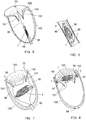
- a catheter 50 is introduced into the left ventricle 103 through the apical area of this ventricle, and a catheter 51 of smaller diameter is engaged into this catheter 50 as far as below the mitral annulus 102.
- a rod 52 with a perforation tip is engaged through this catheter 51 and is used for perforating the mitral annulus 102 in two diametrically opposite locations of the valve 100.
- the catheter 51 After withdrawal of the rod 52, the catheter 51 is engaged through one of the perforations made and a tie 55 with deployable branches, connected to a thread 56, is then pushed into this catheter 51 as far as beyond the perforation, so that the branches of this tie are deployed beyond the annulus 102 (see Fig. 4 ). Traction on the thread 56 gives the possibility of bringing these branches of the tie 55 so that they bear against the annulus (see Fig. 5 ).
- a second tie 55 and a second thread 56 are set into place in the same way in the second perforation (both of these ties 55 and threads 56 are visible in Figs. 7 and 8 ).
- the implant 1 in the contracted state is pushed into the catheter 50 (see Fig. 5 ), with one of these anchoring portions 7 engaged on a thread 56 and the other anchoring portion 7 engaged on the other thread 56 as visible in Fig. 6 .
- the implant is then released from the catheter 50 (see Fig. 7 ) and is pushed on the threads 56 by means of catheters, until its central portion, i.e. the portion covered by the membrane 3, is engaged between the valvulae 101, as shown in Fig. 8 , and that its anchoring portions 7 will come into contact with the mitral annulus 102.
- Each anchoring portion 7 is then attached to the mitral annulus 102 by a known technique, notably by means of washers 57 able to slide on the threads 56 and be clip-fastened on the ties 55 (see Fig. 8 ).
- the threads 56 are then cut by means of a rod with a sharp cutting edge, of a known type, slipped into the catheter 50.
- the implant 1 once it is set into place on the mitral valve 100, will occupy the intervalvular space and said portions 3a of the membrane 3 extending along the edges of the valvulae 101.
- the implant 1 By means of its frame 2, only formed at this membrane 3, by the branches 10 and by the hoop 8, the implant 1 has a longitudinal relative flexibility allowing it to adapt to the shape of the intervalvular space to be filled. In this way, it is perfectly efficient for restoring the seal of the valve 100.
- the pressurized blood from the auricle presses on the portions 3a of the membrane 3 and that brings them into the hollow outwardly concave shape, visible in Fig. 10 ; the implant 1 then has a shape relatively reduced in width, not interfering with the flow of the blood from the auricle to the ventricle.
- the sac formed by the membrane on the ventricular side receives pressurized blood, bringing said portions 3a of the membrane 3 into the convex shape visible in Fig. 11 ; this shape allows the implant 1 to perfectly fill the intervalvular space resulting from the faulty operation of one of the two valvulae 101 and to form efficient supporting surfaces for these valvulae.
- a plug 58 is implanted on the ventricle 103 so as to close the apical orifice made for letting through the catheter 50, see Fig. 8 .
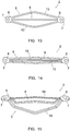
- Figs. 12 and 13 illustrate an implant 1 similar to the one described above but intended to be implanted on the auricular side of the valve 100, via a trans-septal approach.
- the already described elements or parts, which are again found on this implant are designated with the same numerical references.
- the connecting areas 6 and the anchoring portions 7 substantially extend in the extension of the base portion 5, so that the implant 1 is substantially planar outside the hoop 8.
- the anchoring portions 7 are then intended to be connected to the annulus 102 at the commissures of the valvulae 101.
- the branches 10 have a shape, not a stretched oval shape but a chevron shape, giving the base portion a rhombic shape.
- These branches 10 and the hoop 8 are further, also as example, with a rectangular cross-section.
- Fig. 14 shows the frame 2 in the longitudinal contraction state which it adopts when it is placed in the catheter 50.
- Fig. 15 shows a third possible embodiment of the frame 2, with also the use of the same numerical references for designating the already described elements or parts.
- the base portion 5 is formed with chevron-shaped branches 10 therefore having a rhombic shape, and is shifted on the ventricular side of the implant 1, in the same way as described earlier.
- the hoop 8 has a small height as compared with the faces of the anchoring portions 7 intended to come into contact with the annulus 102 of the valve 100, so that the membrane 3 is located sufficiently low in the intervalvular space, and therefore closer to the area for setting the valvulae 101.
- the invention provides an intervalvular implant for a mitral valve having aforementioned determining advantages as compared with homologous implants of the prior art.
Landscapes
- Health & Medical Sciences (AREA)
- Cardiology (AREA)
- Oral & Maxillofacial Surgery (AREA)
- Transplantation (AREA)
- Engineering & Computer Science (AREA)
- Biomedical Technology (AREA)
- Heart & Thoracic Surgery (AREA)
- Vascular Medicine (AREA)
- Life Sciences & Earth Sciences (AREA)
- Animal Behavior & Ethology (AREA)
- General Health & Medical Sciences (AREA)
- Public Health (AREA)
- Veterinary Medicine (AREA)
- Prostheses (AREA)
Claims (13)
- Intervalvuläres Implantat (1) für eine Mitralklappe (100), wobei das Implantat (1) eine Struktur hat, die durch einen Rahmen (2) und durch eine Membran (3) gebildet ist, die diesen Rahmen bedeckt; wobei der Rahmen (2) einen Basisabschnitt (5) und einen Bogen (8) hat, und wobei die Membran (3) mit diesem Bogen (8) verbunden ist;
dadurch gekennzeichnet, dass:- - der Basisabschnitt (5) länglich ist und durch zwei gebogene oder chevronförmige Zweige (10) gebildet ist, wobei diese Zweige (10) mittlere Abschnitte haben, die voneinander entfernt sind, und Endabschnitte, die beim Nähern zueinander laufen und mit Verbindungsbereichen (6) verbunden sind, die an den Längsenden des Basisabschnitts (5) liegen; wobei dieser längliche Basisabschnitt (5) eine Breite hat, die sich vom mittleren Abschnitt eines Zweiges (10) bis zum mittleren Abschnitt des anderen Zweiges (10) erstreckt, und eine Länge, die sich von einem Verbindungsbereich (6) bis zum anderen Verbindungsbereich (6) erstreckt, und so länglich ist, dass die Länge drei- bis achtfach größer als die Breite ist;- der Rahmen (2) Verankerungsabschnitte (7) aufweist, die mit diesen Verbindungsbereichen (6) verbunden sind, so dass das Implantat (1) an dem Ring der Mitralklappe in zwei voneinander beabstandeten Punkten des Ringes, insbesondere einander gegenüber, verankert werden kann;- der Bogen (8) longitudinal ist und sich von einem Verbindungsbereich (6) zu dem anderen erstreckt;- die Membran (3) flexibel ist und sich von einem Zweig (10) zum anderen erstreckt, während sie in der Nähe des Bogens verläuft, wobei diese Membran mit den Zweigen (10) verbunden ist, ohne zwischen diesen Zweigen (10) und diesem Bogen (8) gestreckt zu sein, so dass die beiden seitlichen Abschnitte (3a) der Membran (3), die dadurch auf beiden Seiten des Implantats gebildet sind, entweder eine konkave Form, nach außen konvex, oder eine vertiefte Form, nach außen konkav annehmen können. - Implantat (1) nach Anspruch 1, dadurch gekennzeichnet, dass die Enden der Zweige (10) gekippte Abschnitte aufweisen und/oder die Verbindungsbereiche (6) gekippt sind oder gekippte Abschnitte aufweisen, um den Basisabschnitt (5) auf der ventrikulären Seite des Implantats (1) relativ zu Oberflächen zu verschieben, durch die die Verankerungsabschnitte (7) dazu vorgesehen sind, mit dem Ring der Klappe in Kontakt zu kommen.
- Implantat (1) nach Anspruch 1, dadurch gekennzeichnet, dass sich die Verbindungsbereiche (6) und die Verankerungsabschnitte (7) im Wesentlichen in der Verlängerung des Basisabschnitts (5) erstrecken, so dass sich dieser Basisabschnitt (5) in einer Ebene nahe derjenigen Ebene befindet, in der sich die Oberflächen erstrecken, durch die die Verankerungsabschnitte (7) dazu vorgesehen sind, mit dem Ring der Klappe in Kontakt zu kommen.
- Implantat (1) nach Anspruch 1-3, dadurch gekennzeichnet, dass die Zweige (10) symmetrisch relativ zu einer longitudinalen Mittelebene des Implantats positioniert sind, so dass der Basisabschnitt (5) eine ovale oder rautenförmige Form aufweist.
- Implantat (1) nach Anspruch 1-3, dadurch gekennzeichnet, dass die konvexen oder hervorstehenden Seiten der Zweige, die sich aus der gekrümmten oder chevronförmigen Form dieser Zweige ergeben, ebenfalls in Richtung derselben Seite des Implantats gedreht sind, wodurch sichergestellt wird, dass der Basisabschnitt eine allgemeine gekrümmte Form aufweist, die im Wesentlichen an die Krümmung angepasst ist, die durch den Raum, der durch die Mitralklappen begrenzt ist, dargestellt wird.
- Implantat (1) nach Anspruch 1-5, dadurch gekennzeichnet, dass sich der Bogen (8) in der mittleren Längsebene des Implantats befindet.
- Implantat (1) nach Anspruch 1-6, dadurch gekennzeichnet, dass der Bogen (8) in einer Ebene angeordnet ist, die im Wesentlichen senkrecht zu der Ebene ist, in der sich der Basisabschnitt (5) erstreckt.
- Implantat (1) nach Anspruch 1-7, dadurch gekennzeichnet, dass jeder Verankerungsabschnitt ein Loch zum Aufnehmen eines Bandes (55) zum Verankern des Implantats (1) am mitralen Ring aufweist, wobei dieses Loch länglich ist mit seiner Länge senkrecht zur Länge des Implantats positioniert.
- Implantat (1) nach Anspruch 1-8, dadurch gekennzeichnet, dass sich die Membran (3) entlang des gesamten Abschnitts des Implantats (1) erstreckt, entlang dessen sich der Bogen (8) erstreckt, oder nur an einem Teil dieses Abschnitts.
- Implantat (1) nach Anspruch 1-9, dadurch gekennzeichnet, dass diese Membran (3) um den Bogen (8) herumläuft, wodurch sie gegen ihn drückt.
- Implantat (1) nach Anspruch 1-10, dadurch gekennzeichnet, dass die Membran (3) nur mit den Zweigen (10) verbunden ist, ohne mit dem Bogen (8) verbunden zu sein.
- Implantat (1) nach Anspruch 1-10, dadurch gekennzeichnet, dass die Membran (3) sowohl mit den Zweigen (10) als auch mit dem Bogen (8) verbunden ist.
- Implantat (1) nach Anspruch 1-12, dadurch gekennzeichnet, dass der Rahmen (2) in einem elastisch verformbaren Material ist, das es ihm ermöglicht, eine verformte Konfiguration mit Querkontraktion, in der er in einen Einführungskatheter (50) eingesetzt werden kann, und eine normale Dehnungskonfiguration, in der er implantiert wird, anzunehmen.
Applications Claiming Priority (2)
| Application Number | Priority Date | Filing Date | Title |
|---|---|---|---|
| FR1459917A FR3027212A1 (fr) | 2014-10-16 | 2014-10-16 | Implant intervalvulaire pour valve mitrale |
| PCT/IB2015/057786 WO2016059533A1 (en) | 2014-10-16 | 2015-10-12 | Intervalvular implant for a mitral valve |
Publications (2)
| Publication Number | Publication Date |
|---|---|
| EP3206628A1 EP3206628A1 (de) | 2017-08-23 |
| EP3206628B1 true EP3206628B1 (de) | 2018-12-12 |
Family
ID=51987402
Family Applications (1)
| Application Number | Title | Priority Date | Filing Date |
|---|---|---|---|
| EP15787023.9A Not-in-force EP3206628B1 (de) | 2014-10-16 | 2015-10-12 | Interklappenimplantat für eine mitralklappe |
Country Status (4)
| Country | Link |
|---|---|
| US (1) | US10639154B2 (de) |
| EP (1) | EP3206628B1 (de) |
| FR (1) | FR3027212A1 (de) |
| WO (1) | WO2016059533A1 (de) |
Cited By (17)
| Publication number | Priority date | Publication date | Assignee | Title |
|---|---|---|---|---|
| US10856984B2 (en) | 2017-08-25 | 2020-12-08 | Neovasc Tiara Inc. | Sequentially deployed transcatheter mitral valve prosthesis |
| US11311376B2 (en) | 2019-06-20 | 2022-04-26 | Neovase Tiara Inc. | Low profile prosthetic mitral valve |
| US11357622B2 (en) | 2016-01-29 | 2022-06-14 | Neovase Tiara Inc. | Prosthetic valve for avoiding obstruction of outflow |
| US11389291B2 (en) | 2013-04-04 | 2022-07-19 | Neovase Tiara Inc. | Methods and apparatus for delivering a prosthetic valve to a beating heart |
| US11389294B2 (en) | 2012-05-30 | 2022-07-19 | Neovasc Tiara Inc. | Methods and apparatus for loading a prosthesis onto a delivery system |
| US11399940B2 (en) | 2018-02-08 | 2022-08-02 | Invalve Therapeutics, Inc. | Methods, apparatus and devices to treat heart valves |
| US11413139B2 (en) | 2011-11-23 | 2022-08-16 | Neovasc Tiara Inc. | Sequentially deployed transcatheter mitral valve prosthesis |
| US11419720B2 (en) | 2010-05-05 | 2022-08-23 | Neovasc Tiara Inc. | Transcatheter mitral valve prosthesis |
| US11464631B2 (en) | 2016-11-21 | 2022-10-11 | Neovasc Tiara Inc. | Methods and systems for rapid retraction of a transcatheter heart valve delivery system |
| US11491006B2 (en) | 2019-04-10 | 2022-11-08 | Neovasc Tiara Inc. | Prosthetic valve with natural blood flow |
| US11497602B2 (en) | 2012-02-14 | 2022-11-15 | Neovasc Tiara Inc. | Methods and apparatus for engaging a valve prosthesis with tissue |
| US11602429B2 (en) | 2019-04-01 | 2023-03-14 | Neovasc Tiara Inc. | Controllably deployable prosthetic valve |
| US11737872B2 (en) | 2018-11-08 | 2023-08-29 | Neovasc Tiara Inc. | Ventricular deployment of a transcatheter mitral valve prosthesis |
| US11779742B2 (en) | 2019-05-20 | 2023-10-10 | Neovasc Tiara Inc. | Introducer with hemostasis mechanism |
| US11998447B2 (en) | 2019-03-08 | 2024-06-04 | Neovasc Tiara Inc. | Retrievable prosthesis delivery system |
| US12109111B2 (en) | 2015-12-15 | 2024-10-08 | Neovasc Tiara Inc. | Transseptal delivery system |
| US12611302B2 (en) | 2017-04-18 | 2026-04-28 | Twelve, Inc. | Prosthetic heart valve device and associated systems and methods |
Families Citing this family (39)
| Publication number | Priority date | Publication date | Assignee | Title |
|---|---|---|---|---|
| JP5219518B2 (ja) | 2004-12-09 | 2013-06-26 | ザ ファウンドリー, エルエルシー | 大動脈弁修復 |
| US11013599B2 (en) | 2008-04-16 | 2021-05-25 | Heart Repair Technologies, Inc. | Percutaneous transvalvular intraannular band for mitral valve repair |
| US11083579B2 (en) | 2008-04-16 | 2021-08-10 | Heart Repair Technologies, Inc. | Transvalvular intraanular band and chordae cutting for ischemic and dilated cardiomyopathy |
| CA3035048C (en) | 2010-12-23 | 2021-05-04 | Mark Deem | System for mitral valve repair and replacement |
| CN107496054B (zh) | 2011-06-21 | 2020-03-03 | 托尔福公司 | 人工心脏瓣膜装置及相关系统和方法 |
| US11202704B2 (en) | 2011-10-19 | 2021-12-21 | Twelve, Inc. | Prosthetic heart valve devices, prosthetic mitral valves and associated systems and methods |
| JP6151705B2 (ja) | 2011-10-19 | 2017-06-21 | トゥエルヴ, インコーポレイテッド | 心臓弁置換のためのデバイス、システムおよび方法 |
| US9763780B2 (en) | 2011-10-19 | 2017-09-19 | Twelve, Inc. | Devices, systems and methods for heart valve replacement |
| US10016271B2 (en) | 2011-10-19 | 2018-07-10 | Twelve, Inc. | Prosthetic heart valve devices, prosthetic mitral valves and associated systems and methods |
| US9655722B2 (en) | 2011-10-19 | 2017-05-23 | Twelve, Inc. | Prosthetic heart valve devices, prosthetic mitral valves and associated systems and methods |
| US9039757B2 (en) | 2011-10-19 | 2015-05-26 | Twelve, Inc. | Prosthetic heart valve devices, prosthetic mitral valves and associated systems and methods |
| US9579198B2 (en) | 2012-03-01 | 2017-02-28 | Twelve, Inc. | Hydraulic delivery systems for prosthetic heart valve devices and associated methods |
| EP2999435B1 (de) | 2013-05-20 | 2022-12-21 | Twelve, Inc. | Implantierbare herzklappenvorrichtungen, mitralklappenreparaturvorrichtungen sowie entsprechende systeme |
| EP3200726B1 (de) | 2014-09-29 | 2023-07-05 | The Provost, Fellows, Foundation Scholars, & the other members of Board, of the College of the Holy & Undiv. Trinity of Queen Elizabeth near Dublin | Vorrichtung zur herzklappenbehandlung |
| CN107920895B (zh) | 2015-08-21 | 2020-06-26 | 托尔福公司 | 可植入心脏瓣膜装置、二尖瓣修复装置以及相关系统和方法 |
| US11833034B2 (en) | 2016-01-13 | 2023-12-05 | Shifamed Holdings, Llc | Prosthetic cardiac valve devices, systems, and methods |
| CN116172753A (zh) | 2016-04-29 | 2023-05-30 | 美敦力瓦斯科尔勒公司 | 具有带系绳的锚定件的假体心脏瓣膜设备以及相关联的系统和方法 |
| WO2018119304A1 (en) | 2016-12-22 | 2018-06-28 | Heart Repair Technologies, Inc. | Percutaneous delivery systems for anchoring an implant in a cardiac valve annulus |
| US10575950B2 (en) | 2017-04-18 | 2020-03-03 | Twelve, Inc. | Hydraulic systems for delivering prosthetic heart valve devices and associated methods |
| US10433961B2 (en) | 2017-04-18 | 2019-10-08 | Twelve, Inc. | Delivery systems with tethers for prosthetic heart valve devices and associated methods |
| US10792151B2 (en) | 2017-05-11 | 2020-10-06 | Twelve, Inc. | Delivery systems for delivering prosthetic heart valve devices and associated methods |
| US10646338B2 (en) | 2017-06-02 | 2020-05-12 | Twelve, Inc. | Delivery systems with telescoping capsules for deploying prosthetic heart valve devices and associated methods |
| US10709591B2 (en) | 2017-06-06 | 2020-07-14 | Twelve, Inc. | Crimping device and method for loading stents and prosthetic heart valves |
| US10786352B2 (en) | 2017-07-06 | 2020-09-29 | Twelve, Inc. | Prosthetic heart valve devices and associated systems and methods |
| US10729541B2 (en) | 2017-07-06 | 2020-08-04 | Twelve, Inc. | Prosthetic heart valve devices and associated systems and methods |
| JP7300455B2 (ja) | 2018-02-09 | 2023-06-29 | ザ プロボースト,フェローズ,ファンデーション スカラーズ,アンド ジ アザー メンバーズ オブ ボード,オブ ザ カレッジ オブ ザ ホーリー アンド アンディバイデッド トリニティ オブ クイーン エリザベス ニア ダブリン | 心臓弁療法デバイス |
| DE102018107354A1 (de) | 2018-03-28 | 2019-10-02 | Siempelkamp Maschinen- Und Anlagenbau Gmbh | Streuvorrichtung |
| JP7421546B2 (ja) | 2018-08-21 | 2024-01-24 | シファメド・ホールディングス・エルエルシー | 人工心弁デバイス、システム、および方法 |
| US10912644B2 (en) | 2018-10-05 | 2021-02-09 | Shifamed Holdings, Llc | Prosthetic cardiac valve devices, systems, and methods |
| US10945844B2 (en) * | 2018-10-10 | 2021-03-16 | Edwards Lifesciences Corporation | Heart valve sealing devices and delivery devices therefor |
| JP7489975B2 (ja) | 2018-10-19 | 2024-05-24 | シファメド・ホールディングス・エルエルシー | 調整可能な医療デバイス |
| EP3923869A4 (de) | 2019-02-11 | 2022-11-09 | Heart Repair Technologies, Inc. | Perkutane verabreichungssysteme zur verankerung eines implantats in einem herzklappenring |
| EP4505968A3 (de) | 2019-03-19 | 2025-05-07 | Shifamed Holdings, LLC | Herzklappenprothesenvorrichtungen, systeme |
| CA3148739A1 (en) | 2019-08-05 | 2021-02-11 | Croivalve Ltd. | Apparatus and methods for treating a defective cardiac valve |
| EP4203860A4 (de) | 2020-08-31 | 2024-10-09 | Shifamed Holdings, LLC | Prothesenklappeneinführungssystem |
| JP7835754B2 (ja) | 2020-12-04 | 2026-03-25 | シファメド・ホールディングス・エルエルシー | 張り出し人工心弁送達デバイスおよびシステム |
| WO2022183159A1 (en) | 2021-02-26 | 2022-09-01 | Heart Repair Technologies, Inc. | Transvalvular intraannular implant for valve repair |
| US12201521B2 (en) | 2021-03-22 | 2025-01-21 | Shifamed Holdings, Llc | Anchor position verification for prosthetic cardiac valve devices |
| WO2024044110A1 (en) * | 2022-08-22 | 2024-02-29 | Heart Repair Technologies, Inc. | Transvalvular intraannular implant for valve repair |
Family Cites Families (44)
| Publication number | Priority date | Publication date | Assignee | Title |
|---|---|---|---|---|
| NL143127B (nl) * | 1969-02-04 | 1974-09-16 | Rhone Poulenc Sa | Versterkingsorgaan voor een defecte hartklep. |
| ATE21330T1 (de) | 1982-01-20 | 1986-08-15 | Martin Morris Black | Kuenstliche herzklappen. |
| US5213575A (en) | 1990-03-20 | 1993-05-25 | Scotti Daniel M | Two-piece retrievable catheter forming straight and T-shape configurations |
| US5147391A (en) | 1990-04-11 | 1992-09-15 | Carbomedics, Inc. | Bioprosthetic heart valve with semi-permeable commissure posts and deformable leaflets |
| DK124690D0 (da) | 1990-05-18 | 1990-05-18 | Henning Rud Andersen | Klapprotes til implantering i kroppen for erstatning af naturlig klap samt kateter til brug ved implantering af en saadan klapprotese |
| US5376114A (en) | 1992-10-30 | 1994-12-27 | Jarvik; Robert | Cannula pumps for temporary cardiac support and methods of their application and use |
| US5830239A (en) | 1995-11-15 | 1998-11-03 | Medtronic, Inc. | Natural tissue heart valve fixation apparatus and method |
| EP0850607A1 (de) | 1996-12-31 | 1998-07-01 | Cordis Corporation | Klappenprothese zur Implantation in Körperkanälen |
| JP4162270B2 (ja) | 1997-06-27 | 2008-10-08 | ザ トラスティーズ オブ コロンビア ユニバーシティー イン ザ シティー オブ ニューヨーク | 循環弁修復のための装置 |
| JP2002518131A (ja) | 1998-06-24 | 2002-06-25 | サルザー カーボメディクス インコーポレイテッド | 変化してリーフレット上の最大負荷圧力の位置および大きさに影響を及ぼす心臓弁リーフレット連結構造 |
| US6626899B2 (en) | 1999-06-25 | 2003-09-30 | Nidus Medical, Llc | Apparatus and methods for treating tissue |
| DE60134625D1 (de) | 2000-01-27 | 2008-08-14 | 3F Therapeutics Inc | Herzklappenprothese |
| US20050222489A1 (en) | 2003-10-01 | 2005-10-06 | Ample Medical, Inc. | Devices, systems, and methods for reshaping a heart valve annulus, including the use of a bridge implant |
| WO2004030568A2 (en) | 2002-10-01 | 2004-04-15 | Ample Medical, Inc. | Device and method for repairing a native heart valve leaflet |
| US6461382B1 (en) | 2000-09-22 | 2002-10-08 | Edwards Lifesciences Corporation | Flexible heart valve having moveable commissures |
| US6764510B2 (en) | 2002-01-09 | 2004-07-20 | Myocor, Inc. | Devices and methods for heart valve treatment |
| DE60325634D1 (de) * | 2002-10-01 | 2009-02-12 | Ample Medical Inc | Vorrichtungen und systeme zur umformung eines herzklappen-annulus |
| WO2004032796A2 (en) | 2002-10-10 | 2004-04-22 | The Cleveland Clinic Foundation | Method and apparatus for replacing a mitral valve with a stentless bioprosthetic valve |
| US7404824B1 (en) | 2002-11-15 | 2008-07-29 | Advanced Cardiovascular Systems, Inc. | Valve aptation assist device |
| US7399315B2 (en) | 2003-03-18 | 2008-07-15 | Edwards Lifescience Corporation | Minimally-invasive heart valve with cusp positioners |
| US20050143689A1 (en) | 2003-08-17 | 2005-06-30 | Ramsey Maynard Iii | Internal compression tourniquet catheter system and method for wound track navigation and hemorrhage control |
| US7381219B2 (en) | 2003-12-23 | 2008-06-03 | Sadra Medical, Inc. | Low profile heart valve and delivery system |
| US20050228495A1 (en) * | 2004-01-15 | 2005-10-13 | Macoviak John A | Suspended heart valve devices, systems, and methods for supplementing, repairing, or replacing a native heart valve |
| JP2008513060A (ja) | 2004-09-14 | 2008-05-01 | エドワーズ ライフサイエンシーズ アーゲー | 心臓弁逆流の処置のためのデバイスおよび方法 |
| US7717955B2 (en) | 2005-02-28 | 2010-05-18 | Medtronic, Inc. | Conformable prosthesis for implanting two-piece heart valves and methods for using them |
| US7914569B2 (en) | 2005-05-13 | 2011-03-29 | Medtronics Corevalve Llc | Heart valve prosthesis and methods of manufacture and use |
| WO2007130881A2 (en) | 2006-04-29 | 2007-11-15 | Arbor Surgical Technologies, Inc. | Multiple component prosthetic heart valve assemblies and apparatus and methods for delivering them |
| US20080033541A1 (en) | 2006-08-02 | 2008-02-07 | Daniel Gelbart | Artificial mitral valve |
| US20080249618A1 (en) | 2007-04-09 | 2008-10-09 | Medtronic Vascular, Inc. | Repair of Incompetent Heart Valves by Interstitial Implantation of Space Occupying Materials or Devices |
| US8114154B2 (en) | 2007-09-07 | 2012-02-14 | Sorin Biomedica Cardio S.R.L. | Fluid-filled delivery system for in situ deployment of cardiac valve prostheses |
| WO2010102131A1 (en) | 2009-03-04 | 2010-09-10 | The United States Of America As Represented By The Secretary, Department Of Health And Human Services | Tensioning device and methods for use |
| EP2408399B1 (de) | 2009-03-17 | 2023-11-01 | Mitrassist Medical Ltd. | Herzklappenprothese mit faltbarer klappe |
| US20110022165A1 (en) | 2009-07-23 | 2011-01-27 | Edwards Lifesciences Corporation | Introducer for prosthetic heart valve |
| US9730790B2 (en) | 2009-09-29 | 2017-08-15 | Edwards Lifesciences Cardiaq Llc | Replacement valve and method |
| EP2496181B1 (de) | 2009-11-02 | 2017-08-30 | Symetis SA | Aortenbioprothese und freisetzungssysteme dafür |
| CA2784499C (en) | 2009-12-15 | 2017-04-18 | Edwards Lifesciences Corporation | Expansion device for treatment of vascular passageways |
| US8657872B2 (en) | 2010-07-19 | 2014-02-25 | Jacques Seguin | Cardiac valve repair system and methods of use |
| US8888843B2 (en) | 2011-01-28 | 2014-11-18 | Middle Peak Medical, Inc. | Device, system, and method for transcatheter treatment of valve regurgitation |
| US9011523B2 (en) * | 2011-06-20 | 2015-04-21 | Jacques Seguin | Prosthetic leaflet assembly for repairing a defective cardiac valve and methods of using the same |
| US9549817B2 (en) | 2011-09-22 | 2017-01-24 | Transmural Systems Llc | Devices, systems and methods for repairing lumenal systems |
| WO2013076724A2 (en) * | 2011-11-21 | 2013-05-30 | Mor Research Applications Ltd. | Device for placement in the tricuspid annulus |
| DE102012010798A1 (de) | 2012-06-01 | 2013-12-05 | Universität Duisburg-Essen | Implantierbare Vorrichtung zur Verbesserung oder Behebung einer Herzklappeninsuffizienz |
| US10166098B2 (en) | 2013-10-25 | 2019-01-01 | Middle Peak Medical, Inc. | Systems and methods for transcatheter treatment of valve regurgitation |
| US9629720B2 (en) | 2015-05-04 | 2017-04-25 | Jacques Seguin | Apparatus and methods for treating cardiac valve regurgitation |
-
2014
- 2014-10-16 FR FR1459917A patent/FR3027212A1/fr not_active Withdrawn
-
2015
- 2015-10-12 EP EP15787023.9A patent/EP3206628B1/de not_active Not-in-force
- 2015-10-12 US US15/519,078 patent/US10639154B2/en not_active Expired - Fee Related
- 2015-10-12 WO PCT/IB2015/057786 patent/WO2016059533A1/en not_active Ceased
Non-Patent Citations (1)
| Title |
|---|
| None * |
Cited By (28)
| Publication number | Priority date | Publication date | Assignee | Title |
|---|---|---|---|---|
| US12611303B2 (en) | 2010-05-05 | 2026-04-28 | Neovasc Tiara Inc. | Transcatheter mitral valve prosthesis |
| US11419720B2 (en) | 2010-05-05 | 2022-08-23 | Neovasc Tiara Inc. | Transcatheter mitral valve prosthesis |
| US12053369B2 (en) | 2011-11-23 | 2024-08-06 | Neovasc Tiara Inc. | Sequentially deployed transcatheter mitral valve prosthesis |
| US11413139B2 (en) | 2011-11-23 | 2022-08-16 | Neovasc Tiara Inc. | Sequentially deployed transcatheter mitral valve prosthesis |
| US11497602B2 (en) | 2012-02-14 | 2022-11-15 | Neovasc Tiara Inc. | Methods and apparatus for engaging a valve prosthesis with tissue |
| US12138159B2 (en) | 2012-02-14 | 2024-11-12 | Neovasc Tiara Inc. | Methods and apparatus for engaging a valve prosthesis with tissue |
| US11389294B2 (en) | 2012-05-30 | 2022-07-19 | Neovasc Tiara Inc. | Methods and apparatus for loading a prosthesis onto a delivery system |
| US11617650B2 (en) | 2012-05-30 | 2023-04-04 | Neovasc Tiara Inc. | Methods and apparatus for loading a prosthesis onto a delivery system |
| US11389291B2 (en) | 2013-04-04 | 2022-07-19 | Neovase Tiara Inc. | Methods and apparatus for delivering a prosthetic valve to a beating heart |
| US12109111B2 (en) | 2015-12-15 | 2024-10-08 | Neovasc Tiara Inc. | Transseptal delivery system |
| US12193932B2 (en) | 2016-01-29 | 2025-01-14 | Neovasc Tiara Inc. | Prosthetic valve for avoiding obstruction of outflow |
| US11357622B2 (en) | 2016-01-29 | 2022-06-14 | Neovase Tiara Inc. | Prosthetic valve for avoiding obstruction of outflow |
| US11464631B2 (en) | 2016-11-21 | 2022-10-11 | Neovasc Tiara Inc. | Methods and systems for rapid retraction of a transcatheter heart valve delivery system |
| US12201524B2 (en) | 2016-11-21 | 2025-01-21 | Neovasc Tiara Inc. | Methods and systems for rapid retraction of a transcatheter heart valve delivery system |
| US12611302B2 (en) | 2017-04-18 | 2026-04-28 | Twelve, Inc. | Prosthetic heart valve device and associated systems and methods |
| US11793640B2 (en) | 2017-08-25 | 2023-10-24 | Neovasc Tiara Inc. | Sequentially deployed transcatheter mitral valve prosthesis |
| US10856984B2 (en) | 2017-08-25 | 2020-12-08 | Neovasc Tiara Inc. | Sequentially deployed transcatheter mitral valve prosthesis |
| US11399940B2 (en) | 2018-02-08 | 2022-08-02 | Invalve Therapeutics, Inc. | Methods, apparatus and devices to treat heart valves |
| US11559401B2 (en) | 2018-02-08 | 2023-01-24 | Invalve Therapeutics, Inc. | Methods, apparatus and devices to treat heart valves |
| US12514706B2 (en) | 2018-02-08 | 2026-01-06 | Invalve Therapeutics, Inc. | Methods, apparatus and devices to treat heart valves |
| US11737872B2 (en) | 2018-11-08 | 2023-08-29 | Neovasc Tiara Inc. | Ventricular deployment of a transcatheter mitral valve prosthesis |
| US11998447B2 (en) | 2019-03-08 | 2024-06-04 | Neovasc Tiara Inc. | Retrievable prosthesis delivery system |
| US11602429B2 (en) | 2019-04-01 | 2023-03-14 | Neovasc Tiara Inc. | Controllably deployable prosthetic valve |
| US12036117B2 (en) | 2019-04-10 | 2024-07-16 | Neovasc Tiara Inc. | Prosthetic valve with natural blood flow |
| US11491006B2 (en) | 2019-04-10 | 2022-11-08 | Neovasc Tiara Inc. | Prosthetic valve with natural blood flow |
| US11779742B2 (en) | 2019-05-20 | 2023-10-10 | Neovasc Tiara Inc. | Introducer with hemostasis mechanism |
| US11931254B2 (en) | 2019-06-20 | 2024-03-19 | Neovasc Tiara Inc. | Low profile prosthetic mitral valve |
| US11311376B2 (en) | 2019-06-20 | 2022-04-26 | Neovase Tiara Inc. | Low profile prosthetic mitral valve |
Also Published As
| Publication number | Publication date |
|---|---|
| EP3206628A1 (de) | 2017-08-23 |
| US10639154B2 (en) | 2020-05-05 |
| US20170224477A1 (en) | 2017-08-10 |
| FR3027212A1 (fr) | 2016-04-22 |
| WO2016059533A1 (en) | 2016-04-21 |
Similar Documents
| Publication | Publication Date | Title |
|---|---|---|
| EP3206628B1 (de) | Interklappenimplantat für eine mitralklappe | |
| US12427015B2 (en) | Prosthetic valve and deployment system | |
| US20250143877A1 (en) | Method of implanting a spacer body in a mitral valve | |
| ES3061170T3 (en) | Heart valve sealing devices and delivery devices therefor | |
| US10779936B2 (en) | Percutaneously-deployable prosthetic tricuspid valve | |
| ES2964127T3 (es) | Armazón de comisura flexible | |
| JP6625060B2 (ja) | 経カテーテル式人工弁 | |
| CN106572909B (zh) | 具有缝线夹的环体环 | |
| EP3782585B1 (de) | Künstliche mitralklappe und verankerungsvorrichtung | |
| JP6630282B2 (ja) | 経カテーテル式人工弁 | |
| US9358105B2 (en) | Support device for heart valve prostheses | |
| EP2484309B1 (de) | Herzklappenprothese | |
| US20180133011A1 (en) | Implant for treating a biological valve | |
| JP2016506794A5 (de) | ||
| US20200163768A1 (en) | Systems and methods for treating regurgitating cardiac valves | |
| US12011352B2 (en) | Apparatuses and methods for at least partially supporting a valve leaflet of a regurgitant heart valve | |
| ITUB20159281A1 (it) | Dispositivo per il trattamento percutaneo dell?insufficienza tricuspidale funzionale | |
| HK40049152A (en) | Prosthetic mitral valve and anchoring device |
Legal Events
| Date | Code | Title | Description |
|---|---|---|---|
| STAA | Information on the status of an ep patent application or granted ep patent |
Free format text: STATUS: THE INTERNATIONAL PUBLICATION HAS BEEN MADE |
|
| PUAI | Public reference made under article 153(3) epc to a published international application that has entered the european phase |
Free format text: ORIGINAL CODE: 0009012 |
|
| STAA | Information on the status of an ep patent application or granted ep patent |
Free format text: STATUS: REQUEST FOR EXAMINATION WAS MADE |
|
| 17P | Request for examination filed |
Effective date: 20170414 |
|
| AK | Designated contracting states |
Kind code of ref document: A1 Designated state(s): AL AT BE BG CH CY CZ DE DK EE ES FI FR GB GR HR HU IE IS IT LI LT LU LV MC MK MT NL NO PL PT RO RS SE SI SK SM TR |
|
| AX | Request for extension of the european patent |
Extension state: BA ME |
|
| DAV | Request for validation of the european patent (deleted) | ||
| DAX | Request for extension of the european patent (deleted) | ||
| STAA | Information on the status of an ep patent application or granted ep patent |
Free format text: STATUS: EXAMINATION IS IN PROGRESS |
|
| 17Q | First examination report despatched |
Effective date: 20180202 |
|
| GRAP | Despatch of communication of intention to grant a patent |
Free format text: ORIGINAL CODE: EPIDOSNIGR1 |
|
| STAA | Information on the status of an ep patent application or granted ep patent |
Free format text: STATUS: GRANT OF PATENT IS INTENDED |
|
| INTG | Intention to grant announced |
Effective date: 20180613 |
|
| GRAS | Grant fee paid |
Free format text: ORIGINAL CODE: EPIDOSNIGR3 |
|
| GRAA | (expected) grant |
Free format text: ORIGINAL CODE: 0009210 |
|
| STAA | Information on the status of an ep patent application or granted ep patent |
Free format text: STATUS: THE PATENT HAS BEEN GRANTED |
|
| RAP1 | Party data changed (applicant data changed or rights of an application transferred) |
Owner name: SEGUIN, JACQUES |
|
| RIN1 | Information on inventor provided before grant (corrected) |
Inventor name: SEGUIN, JACQUES |
|
| AK | Designated contracting states |
Kind code of ref document: B1 Designated state(s): AL AT BE BG CH CY CZ DE DK EE ES FI FR GB GR HR HU IE IS IT LI LT LU LV MC MK MT NL NO PL PT RO RS SE SI SK SM TR |
|
| REG | Reference to a national code |
Ref country code: GB Ref legal event code: FG4D |
|
| REG | Reference to a national code |
Ref country code: CH Ref legal event code: EP |
|
| REG | Reference to a national code |
Ref country code: AT Ref legal event code: REF Ref document number: 1075009 Country of ref document: AT Kind code of ref document: T Effective date: 20181215 |
|
| REG | Reference to a national code |
Ref country code: DE Ref legal event code: R096 Ref document number: 602015021540 Country of ref document: DE |
|
| REG | Reference to a national code |
Ref country code: IE Ref legal event code: FG4D |
|
| REG | Reference to a national code |
Ref country code: NL Ref legal event code: FP |
|
| REG | Reference to a national code |
Ref country code: LT Ref legal event code: MG4D |
|
| PG25 | Lapsed in a contracting state [announced via postgrant information from national office to epo] |
Ref country code: LV Free format text: LAPSE BECAUSE OF FAILURE TO SUBMIT A TRANSLATION OF THE DESCRIPTION OR TO PAY THE FEE WITHIN THE PRESCRIBED TIME-LIMIT Effective date: 20181212 Ref country code: FI Free format text: LAPSE BECAUSE OF FAILURE TO SUBMIT A TRANSLATION OF THE DESCRIPTION OR TO PAY THE FEE WITHIN THE PRESCRIBED TIME-LIMIT Effective date: 20181212 Ref country code: BG Free format text: LAPSE BECAUSE OF FAILURE TO SUBMIT A TRANSLATION OF THE DESCRIPTION OR TO PAY THE FEE WITHIN THE PRESCRIBED TIME-LIMIT Effective date: 20190312 Ref country code: NO Free format text: LAPSE BECAUSE OF FAILURE TO SUBMIT A TRANSLATION OF THE DESCRIPTION OR TO PAY THE FEE WITHIN THE PRESCRIBED TIME-LIMIT Effective date: 20190312 Ref country code: LT Free format text: LAPSE BECAUSE OF FAILURE TO SUBMIT A TRANSLATION OF THE DESCRIPTION OR TO PAY THE FEE WITHIN THE PRESCRIBED TIME-LIMIT Effective date: 20181212 Ref country code: HR Free format text: LAPSE BECAUSE OF FAILURE TO SUBMIT A TRANSLATION OF THE DESCRIPTION OR TO PAY THE FEE WITHIN THE PRESCRIBED TIME-LIMIT Effective date: 20181212 |
|
| REG | Reference to a national code |
Ref country code: AT Ref legal event code: MK05 Ref document number: 1075009 Country of ref document: AT Kind code of ref document: T Effective date: 20181212 |
|
| PG25 | Lapsed in a contracting state [announced via postgrant information from national office to epo] |
Ref country code: GR Free format text: LAPSE BECAUSE OF FAILURE TO SUBMIT A TRANSLATION OF THE DESCRIPTION OR TO PAY THE FEE WITHIN THE PRESCRIBED TIME-LIMIT Effective date: 20190313 Ref country code: RS Free format text: LAPSE BECAUSE OF FAILURE TO SUBMIT A TRANSLATION OF THE DESCRIPTION OR TO PAY THE FEE WITHIN THE PRESCRIBED TIME-LIMIT Effective date: 20181212 Ref country code: SE Free format text: LAPSE BECAUSE OF FAILURE TO SUBMIT A TRANSLATION OF THE DESCRIPTION OR TO PAY THE FEE WITHIN THE PRESCRIBED TIME-LIMIT Effective date: 20181212 Ref country code: AL Free format text: LAPSE BECAUSE OF FAILURE TO SUBMIT A TRANSLATION OF THE DESCRIPTION OR TO PAY THE FEE WITHIN THE PRESCRIBED TIME-LIMIT Effective date: 20181212 |
|
| PG25 | Lapsed in a contracting state [announced via postgrant information from national office to epo] |
Ref country code: ES Free format text: LAPSE BECAUSE OF FAILURE TO SUBMIT A TRANSLATION OF THE DESCRIPTION OR TO PAY THE FEE WITHIN THE PRESCRIBED TIME-LIMIT Effective date: 20181212 Ref country code: PT Free format text: LAPSE BECAUSE OF FAILURE TO SUBMIT A TRANSLATION OF THE DESCRIPTION OR TO PAY THE FEE WITHIN THE PRESCRIBED TIME-LIMIT Effective date: 20190412 Ref country code: CZ Free format text: LAPSE BECAUSE OF FAILURE TO SUBMIT A TRANSLATION OF THE DESCRIPTION OR TO PAY THE FEE WITHIN THE PRESCRIBED TIME-LIMIT Effective date: 20181212 Ref country code: PL Free format text: LAPSE BECAUSE OF FAILURE TO SUBMIT A TRANSLATION OF THE DESCRIPTION OR TO PAY THE FEE WITHIN THE PRESCRIBED TIME-LIMIT Effective date: 20181212 Ref country code: IT Free format text: LAPSE BECAUSE OF FAILURE TO SUBMIT A TRANSLATION OF THE DESCRIPTION OR TO PAY THE FEE WITHIN THE PRESCRIBED TIME-LIMIT Effective date: 20181212 |
|
| PG25 | Lapsed in a contracting state [announced via postgrant information from national office to epo] |
Ref country code: IS Free format text: LAPSE BECAUSE OF FAILURE TO SUBMIT A TRANSLATION OF THE DESCRIPTION OR TO PAY THE FEE WITHIN THE PRESCRIBED TIME-LIMIT Effective date: 20190412 Ref country code: SK Free format text: LAPSE BECAUSE OF FAILURE TO SUBMIT A TRANSLATION OF THE DESCRIPTION OR TO PAY THE FEE WITHIN THE PRESCRIBED TIME-LIMIT Effective date: 20181212 Ref country code: SM Free format text: LAPSE BECAUSE OF FAILURE TO SUBMIT A TRANSLATION OF THE DESCRIPTION OR TO PAY THE FEE WITHIN THE PRESCRIBED TIME-LIMIT Effective date: 20181212 Ref country code: EE Free format text: LAPSE BECAUSE OF FAILURE TO SUBMIT A TRANSLATION OF THE DESCRIPTION OR TO PAY THE FEE WITHIN THE PRESCRIBED TIME-LIMIT Effective date: 20181212 Ref country code: RO Free format text: LAPSE BECAUSE OF FAILURE TO SUBMIT A TRANSLATION OF THE DESCRIPTION OR TO PAY THE FEE WITHIN THE PRESCRIBED TIME-LIMIT Effective date: 20181212 |
|
| REG | Reference to a national code |
Ref country code: DE Ref legal event code: R097 Ref document number: 602015021540 Country of ref document: DE |
|
| PLBE | No opposition filed within time limit |
Free format text: ORIGINAL CODE: 0009261 |
|
| STAA | Information on the status of an ep patent application or granted ep patent |
Free format text: STATUS: NO OPPOSITION FILED WITHIN TIME LIMIT |
|
| PG25 | Lapsed in a contracting state [announced via postgrant information from national office to epo] |
Ref country code: SI Free format text: LAPSE BECAUSE OF FAILURE TO SUBMIT A TRANSLATION OF THE DESCRIPTION OR TO PAY THE FEE WITHIN THE PRESCRIBED TIME-LIMIT Effective date: 20181212 Ref country code: DK Free format text: LAPSE BECAUSE OF FAILURE TO SUBMIT A TRANSLATION OF THE DESCRIPTION OR TO PAY THE FEE WITHIN THE PRESCRIBED TIME-LIMIT Effective date: 20181212 Ref country code: AT Free format text: LAPSE BECAUSE OF FAILURE TO SUBMIT A TRANSLATION OF THE DESCRIPTION OR TO PAY THE FEE WITHIN THE PRESCRIBED TIME-LIMIT Effective date: 20181212 |
|
| 26N | No opposition filed |
Effective date: 20190913 |
|
| PG25 | Lapsed in a contracting state [announced via postgrant information from national office to epo] |
Ref country code: TR Free format text: LAPSE BECAUSE OF FAILURE TO SUBMIT A TRANSLATION OF THE DESCRIPTION OR TO PAY THE FEE WITHIN THE PRESCRIBED TIME-LIMIT Effective date: 20181212 |
|
| PGFP | Annual fee paid to national office [announced via postgrant information from national office to epo] |
Ref country code: CH Payment date: 20191125 Year of fee payment: 5 |
|
| PG25 | Lapsed in a contracting state [announced via postgrant information from national office to epo] |
Ref country code: MC Free format text: LAPSE BECAUSE OF FAILURE TO SUBMIT A TRANSLATION OF THE DESCRIPTION OR TO PAY THE FEE WITHIN THE PRESCRIBED TIME-LIMIT Effective date: 20181212 |
|
| PG25 | Lapsed in a contracting state [announced via postgrant information from national office to epo] |
Ref country code: IE Free format text: LAPSE BECAUSE OF NON-PAYMENT OF DUE FEES Effective date: 20191012 |
|
| PGFP | Annual fee paid to national office [announced via postgrant information from national office to epo] |
Ref country code: NL Payment date: 20201028 Year of fee payment: 6 Ref country code: LU Payment date: 20201021 Year of fee payment: 6 |
|
| PGFP | Annual fee paid to national office [announced via postgrant information from national office to epo] |
Ref country code: GB Payment date: 20201022 Year of fee payment: 6 Ref country code: FR Payment date: 20201030 Year of fee payment: 6 Ref country code: DE Payment date: 20201022 Year of fee payment: 6 |
|
| PGFP | Annual fee paid to national office [announced via postgrant information from national office to epo] |
Ref country code: BE Payment date: 20201028 Year of fee payment: 6 |
|
| PG25 | Lapsed in a contracting state [announced via postgrant information from national office to epo] |
Ref country code: CY Free format text: LAPSE BECAUSE OF FAILURE TO SUBMIT A TRANSLATION OF THE DESCRIPTION OR TO PAY THE FEE WITHIN THE PRESCRIBED TIME-LIMIT Effective date: 20181212 |
|
| REG | Reference to a national code |
Ref country code: CH Ref legal event code: PL |
|
| PG25 | Lapsed in a contracting state [announced via postgrant information from national office to epo] |
Ref country code: HU Free format text: LAPSE BECAUSE OF FAILURE TO SUBMIT A TRANSLATION OF THE DESCRIPTION OR TO PAY THE FEE WITHIN THE PRESCRIBED TIME-LIMIT; INVALID AB INITIO Effective date: 20151012 Ref country code: MT Free format text: LAPSE BECAUSE OF FAILURE TO SUBMIT A TRANSLATION OF THE DESCRIPTION OR TO PAY THE FEE WITHIN THE PRESCRIBED TIME-LIMIT Effective date: 20181212 |
|
| PG25 | Lapsed in a contracting state [announced via postgrant information from national office to epo] |
Ref country code: LI Free format text: LAPSE BECAUSE OF NON-PAYMENT OF DUE FEES Effective date: 20201031 Ref country code: CH Free format text: LAPSE BECAUSE OF NON-PAYMENT OF DUE FEES Effective date: 20201031 |
|
| REG | Reference to a national code |
Ref country code: DE Ref legal event code: R119 Ref document number: 602015021540 Country of ref document: DE |
|
| REG | Reference to a national code |
Ref country code: NL Ref legal event code: MM Effective date: 20211101 |
|
| REG | Reference to a national code |
Ref country code: BE Ref legal event code: MM Effective date: 20211031 |
|
| GBPC | Gb: european patent ceased through non-payment of renewal fee |
Effective date: 20211012 |
|
| PG25 | Lapsed in a contracting state [announced via postgrant information from national office to epo] |
Ref country code: MK Free format text: LAPSE BECAUSE OF FAILURE TO SUBMIT A TRANSLATION OF THE DESCRIPTION OR TO PAY THE FEE WITHIN THE PRESCRIBED TIME-LIMIT Effective date: 20181212 |
|
| PG25 | Lapsed in a contracting state [announced via postgrant information from national office to epo] |
Ref country code: NL Free format text: LAPSE BECAUSE OF NON-PAYMENT OF DUE FEES Effective date: 20211101 Ref country code: LU Free format text: LAPSE BECAUSE OF NON-PAYMENT OF DUE FEES Effective date: 20211012 Ref country code: GB Free format text: LAPSE BECAUSE OF NON-PAYMENT OF DUE FEES Effective date: 20211012 Ref country code: DE Free format text: LAPSE BECAUSE OF NON-PAYMENT OF DUE FEES Effective date: 20220503 Ref country code: BE Free format text: LAPSE BECAUSE OF NON-PAYMENT OF DUE FEES Effective date: 20211031 |
|
| PG25 | Lapsed in a contracting state [announced via postgrant information from national office to epo] |
Ref country code: FR Free format text: LAPSE BECAUSE OF NON-PAYMENT OF DUE FEES Effective date: 20211031 |