EP3206731B1 - Commande d'aspiration variable - Google Patents
Commande d'aspiration variable Download PDFInfo
- Publication number
- EP3206731B1 EP3206731B1 EP15790280.0A EP15790280A EP3206731B1 EP 3206731 B1 EP3206731 B1 EP 3206731B1 EP 15790280 A EP15790280 A EP 15790280A EP 3206731 B1 EP3206731 B1 EP 3206731B1
- Authority
- EP
- European Patent Office
- Prior art keywords
- handle
- seal
- shaft
- channel
- suction
- Prior art date
- Legal status (The legal status is an assumption and is not a legal conclusion. Google has not performed a legal analysis and makes no representation as to the accuracy of the status listed.)
- Active
Links
Images



Classifications
-
- A—HUMAN NECESSITIES
- A61—MEDICAL OR VETERINARY SCIENCE; HYGIENE
- A61M—DEVICES FOR INTRODUCING MEDIA INTO, OR ONTO, THE BODY; DEVICES FOR TRANSDUCING BODY MEDIA OR FOR TAKING MEDIA FROM THE BODY; DEVICES FOR PRODUCING OR ENDING SLEEP OR STUPOR
- A61M1/00—Suction or pumping devices for medical purposes; Devices for carrying-off, for treatment of, or for carrying-over, body-liquids; Drainage systems
- A61M1/71—Suction drainage systems
- A61M1/74—Suction control
- A61M1/743—Suction control by changing the cross-section of the line, e.g. flow regulating valves
-
- A—HUMAN NECESSITIES
- A61—MEDICAL OR VETERINARY SCIENCE; HYGIENE
- A61M—DEVICES FOR INTRODUCING MEDIA INTO, OR ONTO, THE BODY; DEVICES FOR TRANSDUCING BODY MEDIA OR FOR TAKING MEDIA FROM THE BODY; DEVICES FOR PRODUCING OR ENDING SLEEP OR STUPOR
- A61M1/00—Suction or pumping devices for medical purposes; Devices for carrying-off, for treatment of, or for carrying-over, body-liquids; Drainage systems
- A61M1/71—Suction drainage systems
- A61M1/76—Handpieces
-
- A—HUMAN NECESSITIES
- A61—MEDICAL OR VETERINARY SCIENCE; HYGIENE
- A61B—DIAGNOSIS; SURGERY; IDENTIFICATION
- A61B17/00—Surgical instruments, devices or methods
- A61B17/22—Implements for squeezing-off ulcers or the like on inner organs of the body; Implements for scraping-out cavities of body organs, e.g. bones; for invasive removal or destruction of calculus using mechanical vibrations; for removing obstructions in blood vessels, not otherwise provided for
- A61B17/225—Implements for squeezing-off ulcers or the like on inner organs of the body; Implements for scraping-out cavities of body organs, e.g. bones; for invasive removal or destruction of calculus using mechanical vibrations; for removing obstructions in blood vessels, not otherwise provided for for extracorporeal shock wave lithotripsy [ESWL], e.g. by using ultrasonic waves
-
- A—HUMAN NECESSITIES
- A61—MEDICAL OR VETERINARY SCIENCE; HYGIENE
- A61B—DIAGNOSIS; SURGERY; IDENTIFICATION
- A61B17/00—Surgical instruments, devices or methods
- A61B17/22—Implements for squeezing-off ulcers or the like on inner organs of the body; Implements for scraping-out cavities of body organs, e.g. bones; for invasive removal or destruction of calculus using mechanical vibrations; for removing obstructions in blood vessels, not otherwise provided for
- A61B2017/22079—Implements for squeezing-off ulcers or the like on inner organs of the body; Implements for scraping-out cavities of body organs, e.g. bones; for invasive removal or destruction of calculus using mechanical vibrations; for removing obstructions in blood vessels, not otherwise provided for with suction of debris
Definitions
- the exemplary and non-limiting embodiments relate generally to a medical instrument and, more particularly, to a medical instrument having a suction control.
- Some medical instruments such as a lithotripter for example, provide suction to remove fluids and debris from inside a patient.
- US 6,193,672 discloses a lavage for suction and removal of body tissues in a patient, comprising a shield formed to include an opening, a cannula defining a cannula interior, the cannula having proximal end and a distal end. The distal end is insertable and positionable in a patient's body.
- the cannula defines a cannula opening to permit access to the cannula interior for the capture of body tissue in the cannula interior.
- the cannula is positioned to lie in the opening formed in the shield.
- An instrument is coupled to the cannula.
- a shield actuator is adapted to be engaged by a user, the shield actuator being coupled to the shield to move the shield relative to the cannula between a first position covering the instrument and a second position exposing the instrument.
- a valve is connected to the cannula for independent actuation to control irrigation and vacuum within the cannula.
- the cannula and valve are integrated into a rigid structure to be held in a user's hand and the valve and shield actuator are operable by the hand of the user that moves the rigidly coupled valve and cannula.
- an example embodiment is provided in an apparatus comprising a housing forming a handle and a shaft, where the shaft extends from the handle, where the housing defines a suction channel from a distal end of the shaft and through the handle; an electrical conductor extending from, the handle through the shaft to the distal end of the shaft; and a suction control valve connected to the suction channel at the handle.
- the suction control valve comprises a valve body having a first channel and a second channel connected to the first channel, where the first channel forms a portion of the suction channel, and where the second channel has a recessed seat at an entrance to the second channel; a valve barrel rotatably connected to the valve body, where the valve barrel comprises a rotatable ring surrounding the valve body and forming a portion of the housing, and wherein the ring comprises an orifice configured to be rotated into and out of registration with an end of the second channel as the ring is rotated about the valve body; and a seal configured to be aligned with the second channel at times the valve barrel is rotated to an open position and to a closed position, the seal comprising a first end and an opposite second end, the first end of the seal is received at the recessed seat, the seal comprising an opening extending from the first end of the seal to the opposite second end of the seal.
- an example embodiment in an apparatus comprising a housing forming a handle and a shaft, where the shaft extends from the handle, where the housing defines a suction channel from a distal end of the shaft and through the handle; an electrical conductor extending from the handle through the shaft to the distal end of the shaft; and a suction control valve connected to the suction channel at the handle.
- the suction control valve comprises an air inlet control value comprising a ring rotatably connected to the handle about a center axis of rotation which is aligned with a longitudinal axis of the handle, the ring comprising an orifice.
- the air inlet control valve also comprises a second channel having a recessed seat at an entrance to the second channel; and a seal configured to be aligned with the second channel at times the ring is rotated to an open position and to a closed position, the seal comprising a first end and an opposite second end, the first end of the seal is received at the recessed seat, the seal comprising an opening extending from the first end of the seal to the opposite second end of the seal.
- an example embodiment is provided in an apparatus comprising a housing forming a handle and a shaft, where the shaft extends from the handle, where the housing defines a suction channel from a distal end of the shaft and through the handle; an electrical conductor extending from the handle through the shaft to the distal end of the shaft; and a suction control valve connected to the suction channel at the handle.
- the suction control valve comprises an air inlet valve member rotatably connected to the handle, where the air inlet valve member comprises an air metering orifice, where the air inlet valve member is configured to rotate the air metering orifice relative to an entrance into an air inlet hole connected to the suction channel to vary suction in the suction channel in the shaft, and where the air metering orifice and/or the entrance to the air inlet hole comprises a non-circular cross section.
- the entrance having a recessed seat;
- the suction control valve also comprises a seal configured to be aligned with the second channel at times the ring is rotated to an open position and to a closed position, the seal comprising a first end and an opposite second end, the first end of the seal is received at the recessed seat, the seal comprising an opening extending from the first end of the seal to the opposite second end of the seal.
- an example method comprises providing a housing of an apparatus with a handle and a shaft, where the shaft extends from the handle, where the housing defines a suction channel from a distal end of the shaft and through the handle; providing an electrical conductor through the handle and to the distal end of the shaft; and connecting a valve barrel to a valve body in the handle, where the valve barrel comprises a rotatable ring extending around the handle and forming a portion of the housing, and wherein the ring comprises an aperture configured to be rotated into and out of registration with an air inlet orifice of the valve body as the ring is rotated about the valve body, the air inlet orifice having a recessed seat; and providing a seal configured to be aligned with the air inlet orifice of the valve body at times the valve barrel is rotated to an open position and to a closed position, the seal comprising a first end and an opposite second end, the first end of the seal is received at the recessed seat, the seal comprising an opening extending
- FIG. 1 there is shown a schematic diagram of a powered surgical instrument system 10 incorporating features of an example embodiment.
- a powered surgical instrument system 10 incorporating features of an example embodiment.
- the features will be described with reference to the example embodiments shown in the drawings, it should be understood that features can be embodied in many alternate forms of embodiments.
- any suitable size, shape or type of elements or materials could be used.
- the powered surgical instrument system 10 includes an apparatus 12, a vacuum or suction source 16, a control unit 18, and a power source 20 such as from a wall outlet for example.
- the suction source 16 may be an external suction source such as provided by attachment to a facility suction outlet provided on a wall.
- the apparatus 12 is a lithotriptor (a device used to crush or fragment a calculus in lithotripsy).
- the apparatus 12 generally comprises a housing 24 which at least partially forms a handle 26 and a shaft 28.
- the shaft 28 extends from the handle 26 in a general cantilever fashion.
- the apparatus 12 has a suction channel 30 which extends through the handle 26 and to the distal end 32 of the shaft 28.
- a rear end 34 of the suction channel 30 is configured to have a suction tube 36 connected thereto.
- the suction tube 36 connects the suction channel 30 to the suction source 16.
- the electrical conductor 22 also extends through the handle 24 and shaft towards the distal end 32.
- a liquid and/or gas fluid source (not shown) may be connected to an endoscope or access sheath (not shown) used by the user/physician during a procedure to provide fluid proximate a location of the distal end 32 of the apparatus 12.
- the apparatus 12 includes an adjustable suction control valve or air inlet valve 38.
- the valve 38 generally comprises a valve body 40 and a valve barrel or actuator 42.
- the valve body 40 is attached, fixedly and stationarily, by fasteners (not shown) to a member 44 of the housing 24.
- the valve barrel 42 is rotatably connected to the valve body 40.
- the valve could comprise a valve stem as the valve actuator which projects into the valve body.
- the valve body 40 is a one piece member comprising a first channel 46, a second channel 48, fastener holes 50, an electrical conductor hole 52, a front projection 54 and a rear projection 56.
- the first channel 46 forms part of the suction channel 30.
- the first channel 46 extends through the front and rear projections 54, 56.
- the rear projection 56 forms the rear end 34 of the suction channel 30.
- the second channel 48 intersects the first channel 46, and extends to a lateral side of the valve body 40.
- This example embodiment shows the valve body with only one second channel 48.
- two or more second channels 48 could be provided, such as located at different radial angles about the center longitudinal axis of the valve body for example.
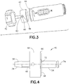
- a recessed seat 58 is located at an entrance to the second channel 48 which has a seal 60 therein (see Fig. 3 ).
- the seal 60 has a hole 62 therethrough.
- the valve body 40 has a main section 64 which has a ledge 66 at a front end 68.
- the ledge 66 is sized and shaped to receive an inwardly extending rim 70 (see Fig. 8 ) of the valve barrel 42.
- the front end 68 also includes a recess 72 extending radially inwardly from the ledge 66.
- the recess 72 has an angle relative to the longitudinal centerline 74 of the valve body 40 of about 45 degrees. However, in alternate embodiments the angle might be more or less than 45 degrees. For example, the angle could be about 60 degrees.
- the valve barrel 42 generally comprises a ring or ring shaped member 76.
- the ring 76 has an orifice 78 therethrough between an outer lateral side 80 and an inner side 82 at a center aperture 84 of the ring 76.
- the ring 76 has a single orifice 78 in this example.
- the ring could comprise two or more orifices, such as located at different radial angles about the centerline of the aperture 84.
- the outer lateral side 80 comprises projections or ridges 86, and recessed areas 88 between the projections 86.
- the entrance into the orifice 78 is located at one of the recessed areas 88 between two of the projections 86.
- the projections 86 provide raised areas for a user's thumb to contact.
- the projections or ridges 86 make rotating the valve barrel 42 about the valve body 40 easier for the user without the user's thumb slipping off the ring 76.
- the rim 70 of the valve barrel 42 is located at the ledge 66 of the valve body 40.
- the rim 70 is rotatably captured between the valve body 40 and the member 44.
- the inner side 82 of the ring 76 in addition to the rim 70, includes an inwardly extending projection 90.
- the projection 90 is located in the recess 72 of the valve body 40.
- the projection 90 is smaller than the recess 72 such that the valve barrel 42 is rotatable about the valve body 40.
- the projection 90 is able to contact opposite sides of the recess 72 to limit axial rotation of the valve barrel about the valve body.
- the projection 90 and the recess 72 function as a rotational limiter to limit axial rotation of the valve barrel 42 about the valve body 40 to a predetermined angle of rotation, such as an angle of between 30-90 degrees for example.
- the orifice 78 in this example has an entrance with a generally non-circular cross sectional shape.
- the shape in this example, comprises a first section 92 with a general circular cross section and a second section 94 with a general non-circular cross section.
- the second section 94 has a general slot shape with a tapered end 96.
- more or less than two sections may be provided, and different shapes other than those shown in this example may be provided.
- the orifice 78 forms an air inlet hole for the entrance into the second channel 48.
- the shape of the orifice 78 is used to vary suction in the suction channel 46; particularly at the entrance into the suction channel at the distal end 32 of the shaft 28.
- the valve barrel 42 is rotatable on the valve body 40 between a first fully closed position of the valve and a second fully open position of the valve.
- the fully closed position comprises the valve barrel 42 completely covering the entrance to the second channel 48 with no portion of the orifice 78 registered with the entrance to the second channel 48.
- the seal 60 seals the entrance to the second channel 48 with the ring 76.
- the fully open position of the valve comprises the first section 92 of the orifice 78 being aligned with the entrance to the second channel 48 such that the ring 76 does not substantially block air from entering the second channel 48.
- the cross sectional size and shape of the first section 92 of the orifice 78 is about the same cross sectional size and shape as the second channel 48. Air flowing into the suction channel 30 from the valve 38 reduces the suction at the entrance to the suction channel 30 at the distal end 32 of the shaft 28.
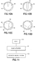
- the valve 38 in this example embodiment, has a plurality of intermediate partially open positions between the fully closed position and the fully open position. Referring also to Figs. 10A-10D , examples of some of the intermediate partially open positions are shown. Based upon the position of the valve barrel relative to the valve body, the aperture through the orifice and the entrance to the second channel 48 changes to vary the amount of air which can enter the second channel 48 through the valve barrel. For example, the size of the aperture increases through the examples of Figs. 10A through 10D .
- the valve 38 may be used to provide a suction control design which uses ingression of air through the side of the handle in order to reduce the vacuum or suction pressure.
- the suction control ring has an orifice geometry that restricts air flow, therefore, allowing the suction flow to be throttled and not simply set to ON or OFF.
- the functional use of features as described herein is to allow a physician to meter the suction during a procedure, and not simply have suction either ON or OFF.
- an example embodiment of the apparatus may comprise a lock 100 and a biasing system 102 connected to the actuator 42 of the valve 38.
- the lock 100 may be configured to lock the position of the actuator 42 relative to the valve body 40.
- the lock 100 may be a user actuated lock for example.
- the lock 100 may be configured to help prevent the position of the valve 38 from inadvertently changing.
- the biasing system 102 may comprise a spring, for example, which is adapted to bias the actuator 42 at a predetermined position relative to the valve body 40.
- the spring could bias the actuator 42 at a position on the handle 26 for the valve 38 to have a fully open position.
- valve 38 would be biased by the biasing system 102 to the fully open position, but the user could manually move the actuator 42 to a fully closed or partially closed position, and then lock the actuator 42 at that position by means of the lock 100.
- the biasing system may maintain the air metering orifice in an open position and the locking member may be used to hold the position of the valve actuator at a desired rotation.
- the lock 100 and/or the biasing system 102 might not be provided.
- An example embodiment may be provide in an apparatus comprising a housing forming a handle and a shaft, where the shaft extends from the handle, where the housing defines a suction channel from a distal end of the shaft and through the handle; an electrical conductor extending from the handle through the shaft to the distal end of the shaft; and a suction control valve connected to the suction channel at the handle.
- the suction control valve comprises a valve body having a first channel and a second channel connected to the first channel, where the first channel forms a portion of the suction channel; and a valve barrel rotatably connected to the valve body, where the valve barrel comprises a rotatable ring extending around the handle and forming a portion of the housing, and wherein the ring comprises an orifice configured to be rotated into and out of registration with an end of the second channel as the ring is rotated about the valve body.
- the orifice may comprise a non-circular cross section.
- the orifice may comprise a first section with a general circular cross section and a second section with general non-circular cross section.
- the ring may be rotatably connected to the handle about a center axis of rotation which is aligned with a longitudinal axis of the handle.
- the ring may comprise ridges extending from an exterior side of the ring, and where the orifice is located between two of the ridges.
- the valve body may comprise a projection extending out of a rear end of the handle, where the first channel extends through the projection, and where the projection is configured to have a suction tube mounted thereon.
- the valve body may comprise a through hole having the electrical conductor extend therethrough.
- the ring may be located around a rear end of the handle.
- the suction control valve may comprise a fully open position, a fully closed position, and at least one partially open position.
- the at least one partially open position may comprise multiple partially open positions to allow a user to variably adjust an amount of air entering the suction channel and thereby vary the suction at the distal end of the shaft.
- the valve barrel may be configured to be moved by a thumb of a hand of a user as the user is grasping the housing at the handle with the hand.
- An example embodiment may be provide in an apparatus comprising a housing forming a handle and a shaft, where the shaft extends from the handle, where the housing defines a suction channel from a distal end of the shaft and through the handle; an electrical conductor extending from the handle through the shaft to the distal end of the shaft; and a suction control valve connected to the suction channel at the handle, where the suction control valve comprises an air inlet control value comprising a ring rotatably connected to the handle about a center axis of rotation which is aligned with a longitudinal axis of the handle.
- An example embodiment may be provide in an apparatus comprising a housing forming a handle and a shaft, where the shaft extends from the handle, where the housing defines a suction channel from a distal end of the shaft and through the handle; an electrical conductor extending from the handle through the shaft to the distal end of the shaft; and a suction control valve connected to the suction channel at the handle, where the suction control valve comprises an air inlet valve member rotatably connected to the handle, where the air inlet valve member comprises an air metering orifice, where the air inlet valve member is configured to rotate the air metering orifice relative to an entrance into an air inlet hole connected to the suction channel to vary suction in the suction channel in the shaft, and where the air metering orifice and/or the entrance to the air inlet hole comprises a non-circular cross section.
- An example method may comprise providing a housing of an apparatus with a handle and a shaft, where the shaft extends from the handle, where the housing defines a suction channel from a distal end of the shaft and through the handle; providing an electrical conductor through the handle and to the distal end of the shaft; and connecting a valve barrel to a valve body in the handle, where the valve barrel comprises a rotatable ring extending around the handle and forming a portion of the housing, and wherein - the ring comprises an aperture configured to be rotated into and out of registration with an air inlet orifice of the valve body as the ring is rotated about the valve body.
- An example method may comprise providing suction in a suction channel extending through a handle and shaft of a medical instrument; and rotating a ring on the handle to vary the suction in the shaft of the medical instrument, where the ring comprises an air metering orifice, where the ring is configured to rotate the air metering orifice relative to an entrance into an air inlet hole connected to the suction channel at the handle to vary suction in the suction channel in the shaft, and where the air metering orifice and/or the entrance to the air inlet hole comprises a non-circular cross section.
Landscapes
- Health & Medical Sciences (AREA)
- Heart & Thoracic Surgery (AREA)
- Life Sciences & Earth Sciences (AREA)
- Animal Behavior & Ethology (AREA)
- Vascular Medicine (AREA)
- Veterinary Medicine (AREA)
- Public Health (AREA)
- Engineering & Computer Science (AREA)
- Biomedical Technology (AREA)
- General Health & Medical Sciences (AREA)
- Anesthesiology (AREA)
- Hematology (AREA)
- Surgery (AREA)
- Molecular Biology (AREA)
- Medical Informatics (AREA)
- Nuclear Medicine, Radiotherapy & Molecular Imaging (AREA)
- Orthopedic Medicine & Surgery (AREA)
- Endoscopes (AREA)
- Surgical Instruments (AREA)
- External Artificial Organs (AREA)
Claims (14)
- Appareil (72) comprenant :un boîtier (24) formant une poignée (26) et un arbre (28), l'arbre s'étend à partir de la poignée, et le boîtier définit un canal d'aspiration (30) à partir d'une extrémité distale (32) de l'arbre et à travers la poignée ;un conducteur électrique (22) s'étendant à partir de la poignée à travers la tige jusqu'à l'extrémité distale de la tige ; etune soupape de commande d'aspiration (38) connectée au canal d'aspiration au niveau de la poignée, la soupape de commande d'aspiration comprend :un corps de soupape (40) ayant un premier canal (46) et un second canal (48) connecté au premier canal, le premier canal forme une partie du canal d'aspiration, le second canal ayant un siège encastré (58) au niveau d'une entrée dans le second canal,un barillet de soupape (42) relié en rotation au corps de soupape, le barillet de soupape comprend un anneau rotatif (76) entourant le corps de soupape et formant une partie du boîtier, l'anneau comprend un orifice (78) configuré pour être tourné dans et hors de l'alignement avec une extrémité du second canal lorsque l'anneau tourne autour du corps de valve ; etun joint d'étanchéité (60) configuré pour être aligné avec le second canal lorsque le barillet de soupape est tourné vers une position ouverte et vers une position fermée, le joint d'étanchéité comprenant une première extrémité et une seconde extrémité opposée, la première extrémité du joint d'étanchéité est reçue au niveau du siège encastré, le joint d'étanchéité comprend une ouverture (62) s'étendant de la première extrémité du joint d'étanchéité à la seconde extrémité opposée du joint d'étanchéité.
- Appareil selon la revendication 1, dans lequel l'orifice a une première section (92) avec une section transversale générale circulaire et une seconde section (94) avec une section transversale générale non circulaire.
- Appareil selon la revendication 1, dans lequel la bague est reliée en rotation à la poignée autour d'un axe central de rotation qui est aligné avec un axe longitudinal de la poignée.
- Appareil selon la revendication 1, dans lequel l'anneau comprend des arêtes (86) s'étendant à partir d'un côté extérieur de l'anneau et dans lequel l'orifice est situé entre deux des arêtes.
- Appareil selon la revendication 1, dans lequel le corps de soupape comprend une saillie (56) s'étendant hors d'une extrémité arrière de la poignée, dans lequel le premier canal s'étend à travers la saillie, et dans lequel la saillie est configurée pour avoir un tube d'aspiration monté sur elle.
- Appareil selon la revendication 1, dans lequel le corps de soupape comprend un trou traversant (52) ayant le conducteur électrique se prolongeant à travers celui-ci.
- Appareil selon la revendication 1, dans lequel l'anneau est situé autour d'une extrémité arrière (34) de la poignée.
- Appareil selon la revendication 1, dans lequel la soupape de commande d'aspiration comprend une position complètement ouverte, une position complètement fermée et au moins une position partiellement ouverte.
- Appareil selon la revendication 8, dans lequel ladite au moins une position partiellement ouverte comprend de multiples positions partiellement ouvertes pour permettre à un utilisateur d'ajuster de manière variable une quantité d'air entrant dans le canal d'aspiration et ainsi faire varier l'aspiration au niveau de l'extrémité distale de la tige.
- Appareil selon la revendication 1, dans lequel le barillet de soupape est configuré pour être déplacé par le pouce d'une main d'un utilisateur lorsque l'utilisateur saisit le boîtier au niveau de la poignée avec la main.
- Appareil selon la revendication 1, comprenant en outre un verrou (100) configuré pour verrouiller le barillet de soupape à une position prédéterminée, et un système de sollicitation (102) configuré pour solliciter le barillet de soupape à une position prédéterminée.
- Appareil (12) comprenant :un boîtier (24) formant une poignée (26) et une tige (28), la tige s'étend à partir de la poignée, le boîtier définit un canal d'aspiration (30) à partir d'une extrémité distale (32) de la tige et à travers la poignée ;un conducteur électrique (22) s'étendant de la poignée à travers la tige jusqu'à l'extrémité distale de la tige ; etune soupape de commande d'aspiration (38) connectée au canal d'aspiration au niveau de la poignée, la soupape de commande d'aspiration comprend :une soupape de commande d'entrée d'air comprenant un anneau (76) relié en rotation à la poignée autour d'un axe central de rotation qui est aligné avec un axe longitudinal de la poignée, l'anneau comprenant un orifice (78) ;un second canal (48) ayant un siège encastré (58) au niveau de l'entrée du second canal ; etun joint d'étanchéité (60) configuré pour être aligné avec le second canal lorsque l'anneau est tourné vers une position ouverte et vers une position fermée, le joint d'étanchéité comprenant une première extrémité et une seconde extrémité opposée, la première extrémité du joint d'étanchéité est reçue au niveau du siège encastré, le joint d'étanchéité comprenant une ouverture (62) s'étendant de la première extrémité du joint d'étanchéité à la seconde extrémité opposée du joint d'étanchéité.
- Appareil (12) comprenant :un boîtier (24) formant une poignée (26) et une tige (28), la tige s'étend à partir de la poignée, et le boîtier définit un canal d'aspiration (30) à partir d'une extrémité distale (32) de la tige et à travers la poignée,un conducteur électrique (22) s'étendant de la poignée à travers la tige jusqu'à l'extrémité distale de la tige ; etune soupape de commande d'aspiration (38) connectée au canal d'aspiration au niveau de la poignée, la soupape de commande d'aspiration comprend :un élément de soupape d'entrée d'air (42) connecté en rotation à la poignée, l'élément de soupape d'entrée d'air comprend un orifice de dosage d'air (18), l'élément de soupape d'entrée d'air est configuré pour faire tourner l'orifice de dosage d'air par rapport à une entrée dans un trou d'entrée d'air (48) connecté au canal d'aspiration pour faire varier l'aspiration dans le canal d'aspiration de la tige, l'orifice de dosage d'air et / ou l'entrée du trou d'entrée d'air comprend une section transversale non circulaire, l'entrée ayant un siège encastré (58) ; etun joint d'étanchéité (60) configuré pour être aligné avec le trou d'entrée d'air lorsque l'élément de soupape d'entrée d'air est tourné vers une position ouverte et vers une position fermée, le joint d'étanchéité comprenant une première extrémité et une seconde extrémité opposée, la première extrémité du joint d'étanchéité est reçue au niveau du siège encastré, le joint d'étanchéité comprenant une ouverture (62) s'étendant de la première extrémité du joint d'étanchéité à la seconde extrémité opposée du joint d'étanchéité.
- Procédé comprenant les étapes consistant à :fournir un boîtier (24) d'un appareil avec une poignée (26) et un arbre (28), l'arbre s'étend depuis la poignée, et le boîtier définit un canal d'aspiration (30) à partir d'une extrémité distale (32) de l'arbre et à travers la poignée,fournir un conducteur électrique (22) à travers la poignée et jusqu'à l'extrémité distale de la tige ;relier un barillet de soupape (42) à un corps de soupape (40) dans la poignée, dans lequel le barillet de soupape comprend un anneau rotatif (16) s'étendant autour de la poignée et formant une partie du boîtier, l'anneau comprend une ouverture (78) configurée pour tourner dans et hors de l'alignement avec un orifice d'entrée d'air du corps de la soupape lorsque l'anneau tourne autour du corps de soupape, l'orifice d'entrée d'air ayant un siège encastré (58) ; etfournir un joint d'étanchéité (60) configuré pour être aligné avec l'orifice d'entrée d'air du corps de soupape lorsque le corps de soupape est tourné vers une position ouverte et vers une position fermée, le joint d'étanchéité comprenant une première extrémité et une seconde extrémité opposée, la première extrémité du joint d'étanchéité est reçue au niveau du siège encastré, le joint d'étanchéité comprenant une ouverture (62) s'étendant de la première extrémité du joint d'étanchéité à la seconde extrémité opposée du joint d'étanchéité.
Priority Applications (1)
| Application Number | Priority Date | Filing Date | Title |
|---|---|---|---|
| EP20155706.3A EP3679960B1 (fr) | 2014-10-16 | 2015-10-12 | Commande d'aspiration variable |
Applications Claiming Priority (2)
| Application Number | Priority Date | Filing Date | Title |
|---|---|---|---|
| US201462064555P | 2014-10-16 | 2014-10-16 | |
| PCT/IB2015/057799 WO2016059538A2 (fr) | 2014-10-16 | 2015-10-12 | Commande d'aspiration variable |
Related Child Applications (2)
| Application Number | Title | Priority Date | Filing Date |
|---|---|---|---|
| EP20155706.3A Division EP3679960B1 (fr) | 2014-10-16 | 2015-10-12 | Commande d'aspiration variable |
| EP20155706.3A Division-Into EP3679960B1 (fr) | 2014-10-16 | 2015-10-12 | Commande d'aspiration variable |
Publications (2)
| Publication Number | Publication Date |
|---|---|
| EP3206731A2 EP3206731A2 (fr) | 2017-08-23 |
| EP3206731B1 true EP3206731B1 (fr) | 2020-06-17 |
Family
ID=54396924
Family Applications (2)
| Application Number | Title | Priority Date | Filing Date |
|---|---|---|---|
| EP20155706.3A Active EP3679960B1 (fr) | 2014-10-16 | 2015-10-12 | Commande d'aspiration variable |
| EP15790280.0A Active EP3206731B1 (fr) | 2014-10-16 | 2015-10-12 | Commande d'aspiration variable |
Family Applications Before (1)
| Application Number | Title | Priority Date | Filing Date |
|---|---|---|---|
| EP20155706.3A Active EP3679960B1 (fr) | 2014-10-16 | 2015-10-12 | Commande d'aspiration variable |
Country Status (6)
| Country | Link |
|---|---|
| US (2) | US10166036B2 (fr) |
| EP (2) | EP3679960B1 (fr) |
| JP (1) | JP6758288B2 (fr) |
| CN (2) | CN110947037B (fr) |
| ES (1) | ES2807619T3 (fr) |
| WO (1) | WO2016059538A2 (fr) |
Cited By (1)
| Publication number | Priority date | Publication date | Assignee | Title |
|---|---|---|---|---|
| US11607484B2 (en) | 2014-10-16 | 2023-03-21 | Gyrus Acmi, Inc. | Variable suction control |
Families Citing this family (3)
| Publication number | Priority date | Publication date | Assignee | Title |
|---|---|---|---|---|
| EP4537867A3 (fr) | 2022-03-02 | 2025-05-21 | Calyxo, Inc. | Système de traitement de calculs rénaux |
| US20240108412A1 (en) | 2022-09-29 | 2024-04-04 | Calyxo, Inc. | Tool guiding device for kidney stone treatment apparatus |
| US20240315533A1 (en) * | 2023-03-24 | 2024-09-26 | Boston Scientific Scimed Inc. | Remote user interface for an endoscope |
Family Cites Families (25)
| Publication number | Priority date | Publication date | Assignee | Title |
|---|---|---|---|---|
| US1313105A (en) * | 1919-08-12 | Faucet | ||
| US3039463A (en) * | 1960-05-09 | 1962-06-19 | Jr James W Dickey | Gastric suction control device |
| US3395705A (en) * | 1965-10-18 | 1968-08-06 | American Hospital Supply Corp | Medical suction apparatus |
| US4595127A (en) | 1984-05-21 | 1986-06-17 | Stoody William R | Self-contained fluid pump aerosol dispenser |
| US4925450A (en) * | 1987-03-20 | 1990-05-15 | The Cooper Companies, Inc. | Surgical aspirator cannula |
| US5019054A (en) * | 1989-11-06 | 1991-05-28 | Mectra Labs, Inc. | Medical device valving mechanism |
| DE9200393U1 (de) * | 1992-01-15 | 1992-03-05 | Ethicon GmbH & Co KG, 2000 Norderstedt | Saug-/Spülvorrichtung für chirurgische Zwecke |
| US5241990A (en) * | 1992-07-10 | 1993-09-07 | Inlet Medical, Inc. | Irrigation/aspiration valve and probe for laparoscopy |
| US6193672B1 (en) | 1993-05-11 | 2001-02-27 | Mectra Labs, Inc. | Lavage |
| US5492527A (en) | 1994-09-09 | 1996-02-20 | Linvatec Corporation | Arthroscopic shaver with rotatable collet and slide aspiration control valve |
| US5830214A (en) * | 1994-11-08 | 1998-11-03 | Heartport, Inc. | Fluid-evacuating electrosurgical device |
| US6129701A (en) * | 1998-11-19 | 2000-10-10 | Sound Surgical Technologies, Llc | Vented aspirator and method |
| JP3609290B2 (ja) * | 1999-06-24 | 2005-01-12 | アロカ株式会社 | 超音波手術器 |
| US6436067B1 (en) | 1999-12-03 | 2002-08-20 | Stryker Corporation | Powered surgical handpiece with suction conduit including a stepped valve to regulate flow through the suction conduit |
| US7682333B2 (en) * | 2002-01-15 | 2010-03-23 | Stryker Corporation | Powered surgical handpiece with precision suction control |
| US6875198B2 (en) * | 2002-05-15 | 2005-04-05 | Kevin T. Foley | Surgical suction regulator valve |
| US9504521B2 (en) * | 2005-03-17 | 2016-11-29 | Stryker Corporation | Surgical tool arrangement |
| US8641728B2 (en) * | 2005-06-13 | 2014-02-04 | Ethicon Endo-Surgery, Inc. | Attachment apparatus for coupling with an endoscope |
| US20080177251A1 (en) * | 2007-01-22 | 2008-07-24 | George Lee | Suction Structure Used For Surgial Operation |
| US7938794B2 (en) * | 2007-05-04 | 2011-05-10 | Sscor, Inc. | Airway suction spoon |
| JP2009006026A (ja) * | 2007-06-29 | 2009-01-15 | Emi Kamijo | 鼻汁吸引補助器 |
| CN102947630B (zh) * | 2010-04-30 | 2015-01-21 | 阿斯顿约翰逊公司 | 用于真空排水系统的真空控制阀门 |
| US20130298540A1 (en) | 2012-05-08 | 2013-11-14 | Essam Tawfik Marcus | Closed-cycle hydro-jet thruster |
| US9351622B2 (en) * | 2012-09-04 | 2016-05-31 | Sapphire Scientific Inc. | Fluid extracting device with shaped head and associated systems and methods of use and manufacture |
| US10166036B2 (en) | 2014-10-16 | 2019-01-01 | Gyrus Acmi, Inc. | Variable suction control |
-
2015
- 2015-09-25 US US14/865,253 patent/US10166036B2/en active Active
- 2015-10-12 CN CN201911234211.0A patent/CN110947037B/zh active Active
- 2015-10-12 JP JP2017520413A patent/JP6758288B2/ja active Active
- 2015-10-12 EP EP20155706.3A patent/EP3679960B1/fr active Active
- 2015-10-12 EP EP15790280.0A patent/EP3206731B1/fr active Active
- 2015-10-12 ES ES15790280T patent/ES2807619T3/es active Active
- 2015-10-12 CN CN201580068189.0A patent/CN107106738B/zh active Active
- 2015-10-12 WO PCT/IB2015/057799 patent/WO2016059538A2/fr not_active Ceased
-
2018
- 2018-12-28 US US16/234,794 patent/US11607484B2/en active Active
Non-Patent Citations (1)
| Title |
|---|
| None * |
Cited By (1)
| Publication number | Priority date | Publication date | Assignee | Title |
|---|---|---|---|---|
| US11607484B2 (en) | 2014-10-16 | 2023-03-21 | Gyrus Acmi, Inc. | Variable suction control |
Also Published As
| Publication number | Publication date |
|---|---|
| JP6758288B2 (ja) | 2020-09-23 |
| JP2017531508A (ja) | 2017-10-26 |
| US10166036B2 (en) | 2019-01-01 |
| ES2807619T3 (es) | 2021-02-23 |
| WO2016059538A2 (fr) | 2016-04-21 |
| EP3679960B1 (fr) | 2025-12-03 |
| CN110947037A (zh) | 2020-04-03 |
| CN110947037B (zh) | 2022-07-08 |
| WO2016059538A3 (fr) | 2016-06-23 |
| US20190133621A1 (en) | 2019-05-09 |
| CN107106738A (zh) | 2017-08-29 |
| EP3679960A3 (fr) | 2020-09-16 |
| CN107106738B (zh) | 2020-01-17 |
| US11607484B2 (en) | 2023-03-21 |
| WO2016059538A4 (fr) | 2016-08-04 |
| US20160106450A1 (en) | 2016-04-21 |
| EP3206731A2 (fr) | 2017-08-23 |
| EP3679960A2 (fr) | 2020-07-15 |
Similar Documents
| Publication | Publication Date | Title |
|---|---|---|
| EP1991288B1 (fr) | Dispositif d'aspiration endoscopique | |
| US20230157521A1 (en) | Medical valve | |
| US11607484B2 (en) | Variable suction control | |
| JP5599824B2 (ja) | 脳腫瘍の外科的除去のためのシステム | |
| JP5866421B2 (ja) | 遠位吸引機能付き外科用切削器具 | |
| CN109152591B (zh) | 具有带握把的切割组件的外科手术器械 | |
| EP4464272B1 (fr) | Ensemble de coupe et ensemble d'entraînement pour un instrument chirurgical | |
| AU2015335613A1 (en) | Suction device for surgical instruments | |
| US9636131B2 (en) | Surgical tool arrangement and surgical cutting accessory for use therewith | |
| EP3281591B1 (fr) | Organe de coupe rotatif de sinuplastie entraîné par turbine | |
| US11793600B2 (en) | Retractable stylet declog mechanism |
Legal Events
| Date | Code | Title | Description |
|---|---|---|---|
| STAA | Information on the status of an ep patent application or granted ep patent |
Free format text: STATUS: THE INTERNATIONAL PUBLICATION HAS BEEN MADE |
|
| PUAI | Public reference made under article 153(3) epc to a published international application that has entered the european phase |
Free format text: ORIGINAL CODE: 0009012 |
|
| STAA | Information on the status of an ep patent application or granted ep patent |
Free format text: STATUS: REQUEST FOR EXAMINATION WAS MADE |
|
| 17P | Request for examination filed |
Effective date: 20170427 |
|
| AK | Designated contracting states |
Kind code of ref document: A2 Designated state(s): AL AT BE BG CH CY CZ DE DK EE ES FI FR GB GR HR HU IE IS IT LI LT LU LV MC MK MT NL NO PL PT RO RS SE SI SK SM TR |
|
| AX | Request for extension of the european patent |
Extension state: BA ME |
|
| DAV | Request for validation of the european patent (deleted) | ||
| DAX | Request for extension of the european patent (deleted) | ||
| STAA | Information on the status of an ep patent application or granted ep patent |
Free format text: STATUS: EXAMINATION IS IN PROGRESS |
|
| 17Q | First examination report despatched |
Effective date: 20181029 |
|
| GRAP | Despatch of communication of intention to grant a patent |
Free format text: ORIGINAL CODE: EPIDOSNIGR1 |
|
| STAA | Information on the status of an ep patent application or granted ep patent |
Free format text: STATUS: GRANT OF PATENT IS INTENDED |
|
| INTG | Intention to grant announced |
Effective date: 20191120 |
|
| GRAS | Grant fee paid |
Free format text: ORIGINAL CODE: EPIDOSNIGR3 |
|
| GRAJ | Information related to disapproval of communication of intention to grant by the applicant or resumption of examination proceedings by the epo deleted |
Free format text: ORIGINAL CODE: EPIDOSDIGR1 |
|
| GRAL | Information related to payment of fee for publishing/printing deleted |
Free format text: ORIGINAL CODE: EPIDOSDIGR3 |
|
| STAA | Information on the status of an ep patent application or granted ep patent |
Free format text: STATUS: EXAMINATION IS IN PROGRESS |
|
| INTC | Intention to grant announced (deleted) | ||
| GRAR | Information related to intention to grant a patent recorded |
Free format text: ORIGINAL CODE: EPIDOSNIGR71 |
|
| STAA | Information on the status of an ep patent application or granted ep patent |
Free format text: STATUS: GRANT OF PATENT IS INTENDED |
|
| GRAA | (expected) grant |
Free format text: ORIGINAL CODE: 0009210 |
|
| STAA | Information on the status of an ep patent application or granted ep patent |
Free format text: STATUS: THE PATENT HAS BEEN GRANTED |
|
| INTG | Intention to grant announced |
Effective date: 20200507 |
|
| AK | Designated contracting states |
Kind code of ref document: B1 Designated state(s): AL AT BE BG CH CY CZ DE DK EE ES FI FR GB GR HR HU IE IS IT LI LT LU LV MC MK MT NL NO PL PT RO RS SE SI SK SM TR |
|
| REG | Reference to a national code |
Ref country code: GB Ref legal event code: FG4D |
|
| REG | Reference to a national code |
Ref country code: CH Ref legal event code: EP |
|
| REG | Reference to a national code |
Ref country code: IE Ref legal event code: FG4D |
|
| REG | Reference to a national code |
Ref country code: DE Ref legal event code: R096 Ref document number: 602015054443 Country of ref document: DE |
|
| REG | Reference to a national code |
Ref country code: AT Ref legal event code: REF Ref document number: 1280544 Country of ref document: AT Kind code of ref document: T Effective date: 20200715 |
|
| PG25 | Lapsed in a contracting state [announced via postgrant information from national office to epo] |
Ref country code: NO Free format text: LAPSE BECAUSE OF FAILURE TO SUBMIT A TRANSLATION OF THE DESCRIPTION OR TO PAY THE FEE WITHIN THE PRESCRIBED TIME-LIMIT Effective date: 20200917 Ref country code: GR Free format text: LAPSE BECAUSE OF FAILURE TO SUBMIT A TRANSLATION OF THE DESCRIPTION OR TO PAY THE FEE WITHIN THE PRESCRIBED TIME-LIMIT Effective date: 20200918 Ref country code: LT Free format text: LAPSE BECAUSE OF FAILURE TO SUBMIT A TRANSLATION OF THE DESCRIPTION OR TO PAY THE FEE WITHIN THE PRESCRIBED TIME-LIMIT Effective date: 20200617 Ref country code: SE Free format text: LAPSE BECAUSE OF FAILURE TO SUBMIT A TRANSLATION OF THE DESCRIPTION OR TO PAY THE FEE WITHIN THE PRESCRIBED TIME-LIMIT Effective date: 20200617 Ref country code: FI Free format text: LAPSE BECAUSE OF FAILURE TO SUBMIT A TRANSLATION OF THE DESCRIPTION OR TO PAY THE FEE WITHIN THE PRESCRIBED TIME-LIMIT Effective date: 20200617 |
|
| REG | Reference to a national code |
Ref country code: LT Ref legal event code: MG4D |
|
| REG | Reference to a national code |
Ref country code: NL Ref legal event code: MP Effective date: 20200617 |
|
| PG25 | Lapsed in a contracting state [announced via postgrant information from national office to epo] |
Ref country code: HR Free format text: LAPSE BECAUSE OF FAILURE TO SUBMIT A TRANSLATION OF THE DESCRIPTION OR TO PAY THE FEE WITHIN THE PRESCRIBED TIME-LIMIT Effective date: 20200617 Ref country code: LV Free format text: LAPSE BECAUSE OF FAILURE TO SUBMIT A TRANSLATION OF THE DESCRIPTION OR TO PAY THE FEE WITHIN THE PRESCRIBED TIME-LIMIT Effective date: 20200617 Ref country code: BG Free format text: LAPSE BECAUSE OF FAILURE TO SUBMIT A TRANSLATION OF THE DESCRIPTION OR TO PAY THE FEE WITHIN THE PRESCRIBED TIME-LIMIT Effective date: 20200917 Ref country code: RS Free format text: LAPSE BECAUSE OF FAILURE TO SUBMIT A TRANSLATION OF THE DESCRIPTION OR TO PAY THE FEE WITHIN THE PRESCRIBED TIME-LIMIT Effective date: 20200617 |
|
| REG | Reference to a national code |
Ref country code: AT Ref legal event code: MK05 Ref document number: 1280544 Country of ref document: AT Kind code of ref document: T Effective date: 20200617 |
|
| PG25 | Lapsed in a contracting state [announced via postgrant information from national office to epo] |
Ref country code: AL Free format text: LAPSE BECAUSE OF FAILURE TO SUBMIT A TRANSLATION OF THE DESCRIPTION OR TO PAY THE FEE WITHIN THE PRESCRIBED TIME-LIMIT Effective date: 20200617 Ref country code: NL Free format text: LAPSE BECAUSE OF FAILURE TO SUBMIT A TRANSLATION OF THE DESCRIPTION OR TO PAY THE FEE WITHIN THE PRESCRIBED TIME-LIMIT Effective date: 20200617 |
|
| PG25 | Lapsed in a contracting state [announced via postgrant information from national office to epo] |
Ref country code: CZ Free format text: LAPSE BECAUSE OF FAILURE TO SUBMIT A TRANSLATION OF THE DESCRIPTION OR TO PAY THE FEE WITHIN THE PRESCRIBED TIME-LIMIT Effective date: 20200617 Ref country code: RO Free format text: LAPSE BECAUSE OF FAILURE TO SUBMIT A TRANSLATION OF THE DESCRIPTION OR TO PAY THE FEE WITHIN THE PRESCRIBED TIME-LIMIT Effective date: 20200617 Ref country code: PT Free format text: LAPSE BECAUSE OF FAILURE TO SUBMIT A TRANSLATION OF THE DESCRIPTION OR TO PAY THE FEE WITHIN THE PRESCRIBED TIME-LIMIT Effective date: 20201019 Ref country code: EE Free format text: LAPSE BECAUSE OF FAILURE TO SUBMIT A TRANSLATION OF THE DESCRIPTION OR TO PAY THE FEE WITHIN THE PRESCRIBED TIME-LIMIT Effective date: 20200617 Ref country code: SM Free format text: LAPSE BECAUSE OF FAILURE TO SUBMIT A TRANSLATION OF THE DESCRIPTION OR TO PAY THE FEE WITHIN THE PRESCRIBED TIME-LIMIT Effective date: 20200617 Ref country code: AT Free format text: LAPSE BECAUSE OF FAILURE TO SUBMIT A TRANSLATION OF THE DESCRIPTION OR TO PAY THE FEE WITHIN THE PRESCRIBED TIME-LIMIT Effective date: 20200617 |
|
| REG | Reference to a national code |
Ref country code: ES Ref legal event code: FG2A Ref document number: 2807619 Country of ref document: ES Kind code of ref document: T3 Effective date: 20210223 |
|
| PG25 | Lapsed in a contracting state [announced via postgrant information from national office to epo] |
Ref country code: SK Free format text: LAPSE BECAUSE OF FAILURE TO SUBMIT A TRANSLATION OF THE DESCRIPTION OR TO PAY THE FEE WITHIN THE PRESCRIBED TIME-LIMIT Effective date: 20200617 Ref country code: PL Free format text: LAPSE BECAUSE OF FAILURE TO SUBMIT A TRANSLATION OF THE DESCRIPTION OR TO PAY THE FEE WITHIN THE PRESCRIBED TIME-LIMIT Effective date: 20200617 Ref country code: IS Free format text: LAPSE BECAUSE OF FAILURE TO SUBMIT A TRANSLATION OF THE DESCRIPTION OR TO PAY THE FEE WITHIN THE PRESCRIBED TIME-LIMIT Effective date: 20201017 |
|
| REG | Reference to a national code |
Ref country code: DE Ref legal event code: R097 Ref document number: 602015054443 Country of ref document: DE |
|
| PLBE | No opposition filed within time limit |
Free format text: ORIGINAL CODE: 0009261 |
|
| STAA | Information on the status of an ep patent application or granted ep patent |
Free format text: STATUS: NO OPPOSITION FILED WITHIN TIME LIMIT |
|
| PG25 | Lapsed in a contracting state [announced via postgrant information from national office to epo] |
Ref country code: DK Free format text: LAPSE BECAUSE OF FAILURE TO SUBMIT A TRANSLATION OF THE DESCRIPTION OR TO PAY THE FEE WITHIN THE PRESCRIBED TIME-LIMIT Effective date: 20200617 |
|
| 26N | No opposition filed |
Effective date: 20210318 |
|
| PG25 | Lapsed in a contracting state [announced via postgrant information from national office to epo] |
Ref country code: SI Free format text: LAPSE BECAUSE OF FAILURE TO SUBMIT A TRANSLATION OF THE DESCRIPTION OR TO PAY THE FEE WITHIN THE PRESCRIBED TIME-LIMIT Effective date: 20200617 |
|
| REG | Reference to a national code |
Ref country code: CH Ref legal event code: PL |
|
| PG25 | Lapsed in a contracting state [announced via postgrant information from national office to epo] |
Ref country code: LU Free format text: LAPSE BECAUSE OF NON-PAYMENT OF DUE FEES Effective date: 20201012 Ref country code: MC Free format text: LAPSE BECAUSE OF FAILURE TO SUBMIT A TRANSLATION OF THE DESCRIPTION OR TO PAY THE FEE WITHIN THE PRESCRIBED TIME-LIMIT Effective date: 20200617 |
|
| REG | Reference to a national code |
Ref country code: BE Ref legal event code: MM Effective date: 20201031 |
|
| PG25 | Lapsed in a contracting state [announced via postgrant information from national office to epo] |
Ref country code: BE Free format text: LAPSE BECAUSE OF NON-PAYMENT OF DUE FEES Effective date: 20201031 Ref country code: CH Free format text: LAPSE BECAUSE OF NON-PAYMENT OF DUE FEES Effective date: 20201031 Ref country code: LI Free format text: LAPSE BECAUSE OF NON-PAYMENT OF DUE FEES Effective date: 20201031 |
|
| PG25 | Lapsed in a contracting state [announced via postgrant information from national office to epo] |
Ref country code: IE Free format text: LAPSE BECAUSE OF NON-PAYMENT OF DUE FEES Effective date: 20201012 |
|
| PG25 | Lapsed in a contracting state [announced via postgrant information from national office to epo] |
Ref country code: TR Free format text: LAPSE BECAUSE OF FAILURE TO SUBMIT A TRANSLATION OF THE DESCRIPTION OR TO PAY THE FEE WITHIN THE PRESCRIBED TIME-LIMIT Effective date: 20200617 Ref country code: MT Free format text: LAPSE BECAUSE OF FAILURE TO SUBMIT A TRANSLATION OF THE DESCRIPTION OR TO PAY THE FEE WITHIN THE PRESCRIBED TIME-LIMIT Effective date: 20200617 Ref country code: CY Free format text: LAPSE BECAUSE OF FAILURE TO SUBMIT A TRANSLATION OF THE DESCRIPTION OR TO PAY THE FEE WITHIN THE PRESCRIBED TIME-LIMIT Effective date: 20200617 |
|
| PG25 | Lapsed in a contracting state [announced via postgrant information from national office to epo] |
Ref country code: MK Free format text: LAPSE BECAUSE OF FAILURE TO SUBMIT A TRANSLATION OF THE DESCRIPTION OR TO PAY THE FEE WITHIN THE PRESCRIBED TIME-LIMIT Effective date: 20200617 |
|
| P01 | Opt-out of the competence of the unified patent court (upc) registered |
Effective date: 20230518 |
|
| PGFP | Annual fee paid to national office [announced via postgrant information from national office to epo] |
Ref country code: DE Payment date: 20251029 Year of fee payment: 11 |
|
| PGFP | Annual fee paid to national office [announced via postgrant information from national office to epo] |
Ref country code: GB Payment date: 20251027 Year of fee payment: 11 |
|
| PGFP | Annual fee paid to national office [announced via postgrant information from national office to epo] |
Ref country code: IT Payment date: 20251021 Year of fee payment: 11 |
|
| PGFP | Annual fee paid to national office [announced via postgrant information from national office to epo] |
Ref country code: FR Payment date: 20251027 Year of fee payment: 11 |
|
| PGFP | Annual fee paid to national office [announced via postgrant information from national office to epo] |
Ref country code: ES Payment date: 20251103 Year of fee payment: 11 |