EP3206811B1 - Procédé de production d'un arbre creux profilé pour arbre de direction télescopique d'un véhicule automobile - Google Patents
Procédé de production d'un arbre creux profilé pour arbre de direction télescopique d'un véhicule automobile Download PDFInfo
- Publication number
- EP3206811B1 EP3206811B1 EP15747433.9A EP15747433A EP3206811B1 EP 3206811 B1 EP3206811 B1 EP 3206811B1 EP 15747433 A EP15747433 A EP 15747433A EP 3206811 B1 EP3206811 B1 EP 3206811B1
- Authority
- EP
- European Patent Office
- Prior art keywords
- hollow shaft
- shaft
- profile
- groove
- roller
- Prior art date
- Legal status (The legal status is an assumption and is not a legal conclusion. Google has not performed a legal analysis and makes no representation as to the accuracy of the status listed.)
- Active
Links
Images

Classifications
-
- B—PERFORMING OPERATIONS; TRANSPORTING
- B62—LAND VEHICLES FOR TRAVELLING OTHERWISE THAN ON RAILS
- B62D—MOTOR VEHICLES; TRAILERS
- B62D1/00—Steering controls, i.e. means for initiating a change of direction of the vehicle
- B62D1/02—Steering controls, i.e. means for initiating a change of direction of the vehicle vehicle-mounted
- B62D1/16—Steering columns
-
- F—MECHANICAL ENGINEERING; LIGHTING; HEATING; WEAPONS; BLASTING
- F16—ENGINEERING ELEMENTS AND UNITS; GENERAL MEASURES FOR PRODUCING AND MAINTAINING EFFECTIVE FUNCTIONING OF MACHINES OR INSTALLATIONS; THERMAL INSULATION IN GENERAL
- F16C—SHAFTS; FLEXIBLE SHAFTS; ELEMENTS OR CRANKSHAFT MECHANISMS; ROTARY BODIES OTHER THAN GEARING ELEMENTS; BEARINGS
- F16C3/00—Shafts; Axles; Cranks; Eccentrics
- F16C3/02—Shafts; Axles
- F16C3/03—Shafts; Axles telescopic
-
- B—PERFORMING OPERATIONS; TRANSPORTING
- B21—MECHANICAL METAL-WORKING WITHOUT ESSENTIALLY REMOVING MATERIAL; PUNCHING METAL
- B21D—WORKING OR PROCESSING OF SHEET METAL OR METAL TUBES, RODS OR PROFILES WITHOUT ESSENTIALLY REMOVING MATERIAL; PUNCHING METAL
- B21D15/00—Corrugating tubes
- B21D15/02—Corrugating tubes longitudinally
-
- B—PERFORMING OPERATIONS; TRANSPORTING
- B21—MECHANICAL METAL-WORKING WITHOUT ESSENTIALLY REMOVING MATERIAL; PUNCHING METAL
- B21D—WORKING OR PROCESSING OF SHEET METAL OR METAL TUBES, RODS OR PROFILES WITHOUT ESSENTIALLY REMOVING MATERIAL; PUNCHING METAL
- B21D17/00—Forming single grooves in sheet metal or tubular or hollow articles
- B21D17/04—Forming single grooves in sheet metal or tubular or hollow articles by rolling
-
- B—PERFORMING OPERATIONS; TRANSPORTING
- B21—MECHANICAL METAL-WORKING WITHOUT ESSENTIALLY REMOVING MATERIAL; PUNCHING METAL
- B21H—MAKING PARTICULAR METAL OBJECTS BY ROLLING, e.g. SCREWS, WHEELS, RINGS, BARRELS, BALLS
- B21H1/00—Making articles shaped as bodies of revolution
- B21H1/18—Making articles shaped as bodies of revolution cylinders, e.g. rolled transversely cross-rolling
- B21H1/20—Making articles shaped as bodies of revolution cylinders, e.g. rolled transversely cross-rolling rolled longitudinally
-
- B—PERFORMING OPERATIONS; TRANSPORTING
- B21—MECHANICAL METAL-WORKING WITHOUT ESSENTIALLY REMOVING MATERIAL; PUNCHING METAL
- B21H—MAKING PARTICULAR METAL OBJECTS BY ROLLING, e.g. SCREWS, WHEELS, RINGS, BARRELS, BALLS
- B21H7/00—Making articles not provided for in the preceding groups, e.g. agricultural tools, dinner forks, knives, spoons
- B21H7/18—Making articles not provided for in the preceding groups, e.g. agricultural tools, dinner forks, knives, spoons grooved pins; Rolling grooves, e.g. oil grooves, in articles
- B21H7/187—Rolling helical or rectilinear grooves
-
- B—PERFORMING OPERATIONS; TRANSPORTING
- B21—MECHANICAL METAL-WORKING WITHOUT ESSENTIALLY REMOVING MATERIAL; PUNCHING METAL
- B21K—MAKING FORGED OR PRESSED METAL PRODUCTS, e.g. HORSE-SHOES, RIVETS, BOLTS OR WHEELS
- B21K1/00—Making machine elements
- B21K1/06—Making machine elements axles or shafts
- B21K1/063—Making machine elements axles or shafts hollow
-
- F—MECHANICAL ENGINEERING; LIGHTING; HEATING; WEAPONS; BLASTING
- F16—ENGINEERING ELEMENTS AND UNITS; GENERAL MEASURES FOR PRODUCING AND MAINTAINING EFFECTIVE FUNCTIONING OF MACHINES OR INSTALLATIONS; THERMAL INSULATION IN GENERAL
- F16D—COUPLINGS FOR TRANSMITTING ROTATION; CLUTCHES; BRAKES
- F16D3/00—Yielding couplings, i.e. with means permitting movement between the connected parts during the drive
- F16D3/02—Yielding couplings, i.e. with means permitting movement between the connected parts during the drive adapted to specific functions
- F16D3/06—Yielding couplings, i.e. with means permitting movement between the connected parts during the drive adapted to specific functions specially adapted to allow axial displacement
-
- F—MECHANICAL ENGINEERING; LIGHTING; HEATING; WEAPONS; BLASTING
- F16—ENGINEERING ELEMENTS AND UNITS; GENERAL MEASURES FOR PRODUCING AND MAINTAINING EFFECTIVE FUNCTIONING OF MACHINES OR INSTALLATIONS; THERMAL INSULATION IN GENERAL
- F16C—SHAFTS; FLEXIBLE SHAFTS; ELEMENTS OR CRANKSHAFT MECHANISMS; ROTARY BODIES OTHER THAN GEARING ELEMENTS; BEARINGS
- F16C2326/00—Articles relating to transporting
- F16C2326/20—Land vehicles
- F16C2326/24—Steering systems, e.g. steering rods or columns
-
- F—MECHANICAL ENGINEERING; LIGHTING; HEATING; WEAPONS; BLASTING
- F16—ENGINEERING ELEMENTS AND UNITS; GENERAL MEASURES FOR PRODUCING AND MAINTAINING EFFECTIVE FUNCTIONING OF MACHINES OR INSTALLATIONS; THERMAL INSULATION IN GENERAL
- F16D—COUPLINGS FOR TRANSMITTING ROTATION; CLUTCHES; BRAKES
- F16D2250/00—Manufacturing; Assembly
-
- F—MECHANICAL ENGINEERING; LIGHTING; HEATING; WEAPONS; BLASTING
- F16—ENGINEERING ELEMENTS AND UNITS; GENERAL MEASURES FOR PRODUCING AND MAINTAINING EFFECTIVE FUNCTIONING OF MACHINES OR INSTALLATIONS; THERMAL INSULATION IN GENERAL
- F16D—COUPLINGS FOR TRANSMITTING ROTATION; CLUTCHES; BRAKES
- F16D3/00—Yielding couplings, i.e. with means permitting movement between the connected parts during the drive
- F16D3/16—Universal joints in which flexibility is produced by means of pivots or sliding or rolling connecting parts
- F16D3/26—Hooke's joints or other joints with an equivalent intermediate member to which each coupling part is pivotally or slidably connected
- F16D3/38—Hooke's joints or other joints with an equivalent intermediate member to which each coupling part is pivotally or slidably connected with a single intermediate member with trunnions or bearings arranged on two axes perpendicular to one another
- F16D3/40—Hooke's joints or other joints with an equivalent intermediate member to which each coupling part is pivotally or slidably connected with a single intermediate member with trunnions or bearings arranged on two axes perpendicular to one another with intermediate member provided with two pairs of outwardly-directed trunnions on intersecting axes
Definitions
- the present invention relates to a method for producing a profiled hollow shaft for a telescopic steering shaft of a motor vehicle, comprising the provision of a hollow shaft to be machined as well as a profile mandrel and a roller head having at least one roller, the profile mandrel for producing a groove in the hollow shaft first in the hollow shaft is introduced and then the hollow shaft is moved relative to the roller head.
- Telescopic steering shafts in motor vehicles on the one hand enable the steering column to be adjusted, and on the other hand they are intended to prevent the steering shaft from moving further into the interior of the passenger compartment in the event of a crash and leading to injuries to the occupants. This is usually achieved by providing two mutually telescopic shafts or hollow shafts, which together form a steering shaft. Furthermore, adjustment of the steering wheel position in the longitudinal direction can be achieved due to the telescopability.
- the hollow shafts are provided with profiles which correspond to one another and which on the one hand enable displacement in the longitudinal direction and on the other hand to transmit a torque.
- the profiles must be easy to move and play against each other, it is particularly important to avoid twisting or kinking.
- hollow shafts with high wall thicknesses are conventionally used.
- step-by-step machining is generally carried out, the hollow shafts first being pushed onto a profile mandrel. Molding tools, such as rollers, then act on the outer peripheral surfaces of hollow shafts.
- the hollow shaft can be adapted to the profile of the profile mandrel, and on the other hand a corresponding profile can be created on the outer peripheral surface. Due to the high material thickness of the hollow shafts and the associated high rolling forces, the profiling of the hollow shafts is generally only gradual, with the material flowing.
- the molds work in the longitudinal and circumferential direction step by step over the hollow shaft and thus create the desired profile.
- the step-by-step generation of the profiling of the hollow shafts leads to high cycle times, which drive up the manufacturing costs of the profiled hollow shafts.
- the CH 579427 A5 shows for example a method for manufacturing a tubular, straight inner and outer profile.
- the disadvantage of this solution is the continuous workpiece rotation, which results in long cycle times.
- a method for producing a profiled hollow shaft for a telescopic steering shaft of a motor vehicle comprises the provision of a hollow shaft to be machined and a profile mandrel and a roller head having at least one roller, the profile mandrel first of all creating a groove in the hollow shaft in the hollow shaft is introduced and then the hollow shaft is moved relative to the roller head.
- a groove is formed to form a groove Movement of the hollow shaft relative to the roller head only in the direction of the longitudinal axis of the hollow shaft.
- the roller of the roller head preferably has a defined and, at least for the production cycle, unchangeable radial distance from the hollow shaft.
- the hollow shaft comprises an outer circumferential surface with an outer diameter, the radial distance of the roller being less than the outer diameter of the hollow shafts.
- the method enables simplified production, in particular for coarse tooth shapes on hollow shafts. Since the hollow shaft only has to be moved in the direction of its longitudinal axis relative to the rolling head in order to form a groove in the hollow shaft, the machining can readily be carried out in the cold rolling process.
- the profile mandrel is moved together with the hollow shaft and the movement of the profile mandrel and the hollow shaft relative to the roller head occurs exclusively in the direction of the longitudinal axis of the hollow shaft.
- the at least one groove with a groove length is produced on the hollow shaft by a forward stroke movement of the hollow shaft relative to the roller head along the groove length, the roller of the roller head rolling on the hollow shaft in the longitudinal direction.
- the continuous forward stroke movement is understood to mean a relative movement of the hollow shaft relative to the roller head over the entire groove length without a reversal of direction.
- the movement is preferably carried out at a constant speed or with a defined speed profile.
- the groove on the hollow shaft is produced by a continuous forward stroke movement, it is sufficient that the hollow shaft is moved once in the longitudinal direction relative to the roller head and in particular the roller of the roller head.
- the roller acts with a force on the hollow shaft to form the groove on it. Accordingly, the machining time required to create a groove on the hollow shaft can be reduced. Since the roller of the roller head rolls on the hollow shaft only in the direction of the longitudinal axis, there is a simple relative movement between the hollow shaft and the roller head, which does not require any complex coordination.
- At least one groove on the hollow shaft can preferably be produced by a double stroke movement of the hollow shaft relative to the roller head.
- This has the advantage that no additional movements are required to separate the hollow shaft together with the mandrel from the roller head or to move it out of the latter.
- the hollow shaft is brought into contact with the roll of the rolling head together with the mandrel by a preliminary stroke movement relative to the rolling head, and a groove is produced in the direction of the longitudinal axis of the hollow shaft in the hollow shaft.
- the pre-stroke movement ends when the desired groove length is reached.
- a return stroke movement in which the hollow shaft moves together with the profile mandrel in the opposite direction of the preliminary stroke movement relatively in the direction of the longitudinal axis of the hollow shaft.
- the groove created during the preliminary stroke movement is rolled again by the roller of the roller head.
- the hollow shaft is finally withdrawn relative to the roller head.
- the contact between the roller of the roller head and the hollow shaft can be separated. Accordingly, a rolling process for creating a groove in the hollow shaft can be completed. This is particularly advantageous if the groove length is less than the length of the hollow shaft or in other words if the groove is only partially formed on the hollow shaft.
- all the grooves present in the hollow shaft are produced by a common work step with a continuous forward stroke movement.
- a separate roller is preferably provided in the rolling head, the rollers for producing the grooves simultaneously rolling on the hollow shaft.
- the entire forming process for producing the grooves in the hollow shaft can be carried out by means of an axial relative movement of the profile mandrel and the hollow shaft relative to the rollers of the roller head. This results in a significant time saving, so that significantly shorter cycle times for profiling the hollow shaft or for forming the grooves in the hollow shaft are possible compared to conventional manufacturing processes.
- a simultaneous formation of the grooves to be produced in the hollow shaft with a symmetrical arrangement of the grooves in the hollow shaft can lead to an essentially symmetrical force effect of the rollers of the roller head in the radial direction on the hollow shaft or the profile mandrel.
- This is particularly advantageous for the design of the roller head.
- a symmetrical progression of forces means that there are fewer requirements for the supporting effect of the individual components of the roller head.
- the symmetrical course of forces considerably reduces the moments that occur in a bearing of the roller head, which can lead to a reduction in the design and manufacturing costs of the roller head.
- a symmetrical force effect also has a positive effect on the properties of the profiled hollow shaft.
- the hollow shaft experiences even bending processes during cold forming, so that even grooves are created on the hollow shaft.
- the result is a symmetrical body of revolution with a homogeneous material distribution.
- a method for producing a telescopic steering shaft for a motor vehicle wherein an inner hollow shaft with its groove profile is inserted into an outer hollow shaft with a groove profile, the groove profile of the outer hollow shaft being in a continuous forward stroke movement along the longitudinal axis of the steering shaft by means of at least one roller is calibrated to the groove profile of the inner hollow shaft.
- the groove profile of the outer hollow shaft clings to the groove profile of the inner hollow shaft.
- the nestling minimizes the existing play between the inner and outer hollow shaft, so that a low-play and smoothly telescopic steering shaft can be provided.
- a profile mandrel can preferably be inserted into the inner hollow shaft, the profile mandrel serving for the inner support and thus counteracting an undesired deformation of the inner and outer hollow shaft.
- the at least one roller calibrates the grooves of the outer hollow shaft, the inner and outer hollow shaft are telescoped against one another in their longitudinal direction. This can preferably be done in an oscillating manner so that a back and forth movement is carried out. Experiments have shown that this oscillating movement leads to a further minimization of the game. It has also been shown that a lubricant present between the inner hollow shaft and the outer hollow shaft is optimally distributed.
- a plastic sleeve which is arranged between the hollow shafts after the hollow shaft has been inserted is applied to the inner hollow shaft before the inner hollow shaft is inserted into the outer hollow shaft, the three components being calibrated with respect to one another.
- the plastic sleeve enables better sliding properties while telescoping the steering shaft.
- a particularly low-backlash and torsionally rigid steering shaft can be provided on account of the reduction in play in the groove profile of the outer hollow shaft.
- the present invention is also achieved by a steering shaft with the features of claim 8. Advantageous refinements result from the subclaims.
- a steering shaft for a motor vehicle which comprises an inner shaft and an outer shaft, which are arranged coaxially to one another and are telescopic against one another, the inner shaft and the outer shaft having a profile of mutually corresponding grooves.
- at least one of the two shafts of the steering shaft is produced by the above-mentioned method.
- this steering shaft can be designed as a steering intermediate shaft, wherein this steering intermediate shaft comprises at least one universal joint, or as a steering spindle, such a steering spindle being rotatably mounted in a steering column and comprising a coupling section for connecting a steering wheel.
- a flank angle ⁇ of the grooves in the outer shaft and / or the inner shaft and the flank angle ⁇ of a profile head of an internal toothing of the outer shaft and / or the inner shaft is 45 ° to 75 °, preferably 55 ° to 65 ° and particularly preferably 60 °.
- the angle ⁇ corresponds to the angle of the two tooth flanks of a tooth of an internal toothing of the outer shaft.
- Two opposite tooth flanks of an external toothing of the inner shaft have the same angle ⁇ .
- the opposite tooth flanks also form the side walls of one in the inner shaft generated groove. This makes it possible for a tooth of the inner toothing of the outer shaft to correspond to a groove of the outer toothing of the inner shaft.
- a flank angle ⁇ of 45 ° to 75 ° enables the inner shaft and the outer shaft to be positively engaged for torque transmission and at the same time are displaceable in the direction of the longitudinal axis of the steering shaft.
- the flank angle ⁇ from 45 ° to 75 ° further enables the inner shaft and the outer shaft to transmit torsional forces acting on the steering shaft and, at the same time, the risk of the inner shaft wedging with the outer shaft due to the springback of the flanks, which leads to an impairment of the displaceability to one another in the longitudinal direction can be kept low.
- Investigations have shown that a preferred flank angle ⁇ of 55 ° to 65 ° provides improved results with regard to the susceptibility to tolerance of the inner and outer shaft, which can be telescoped relative to one another, and the torsional rigidity.
- An angle with the value of 60 ° was determined as the optimal flank angle ⁇ . This optimal flank angle showed little play between the inner and outer shaft and high torsional rigidity.
- the ratio of the difference between an inner diameter of a profile head of an external toothing and an inner diameter of a groove bottom of an internal toothing of the inner shaft and / or the outer shaft to a material thickness of the inner shaft and / or the outer shaft is between 1 and 4.
- the ratio is preferably between 1.5 and 3.5 and particularly preferably between 2 and 3, since ideal conditions for the introduction of the grooves according to the above-mentioned method are present.
- a minimum wall thickness of the inner shaft and / or the outer shaft which is 25% of the difference between the inner diameter of a tooth of the outer toothing and the inner diameter of a tooth of the inner toothing of the inner shaft and / or the outer wave is not to be undercut.
- the inner shaft and / or the outer shaft has an at least partially circular-cylindrical or a polygonal hollow cross-sectional profile before the introduction of the at least one groove, based on the shaft longitudinal axis.
- the hollow cross section is preferably a triple or quadruple.
- a sleeve with a profile is arranged between the inner shaft and the outer shaft, which corresponds to the profile of the inner shaft and the profile of the outer shaft.
- the sleeve contributes to the fact that the play between the contact surfaces of the inner shaft and the outer shaft can be reduced or prevented.
- the sleeve can allow smooth movement of the inner shaft relative to the outer shaft. Accordingly, the sleeve can allow the steering shaft to be adjusted to a low and constant level of force.
- the sleeve is made of plastic. This makes it possible to easily and quickly adapt the inner profile of the sleeve and the outer profile of the sleeve to the profile of the inner shaft and the outer shaft in order to achieve a longitudinal displacement of the steering shaft with a defined force level. Furthermore, a sleeve made of plastic enables a reduction in the Noise formation when using the steering shaft.
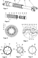
- a steering shaft 10 can be seen for a motor vehicle.
- the steering shaft 10 has an outer shaft 20 and an inner shaft 30, which are telescopic against each other are.
- the outer shaft 20 has a fork 21, which forms part of a universal joint (not shown), in order to integrate the steering shaft 10 in a steering train.
- the inner shaft 30 also has a fork 31 at an outer end, which fork forms part of a universal joint (not shown) in order to integrate the steering shaft 10 into the steering train.
- the outer shaft 20 and the inner shaft 30 are hollow shafts, which are made of a steel with good forming properties.
- the outer shaft 20 and the inner shaft 30 can also be made of aluminum alloys, stainless steel and the like.
- Figures 1 and 2 it can be seen that the outer shaft 20 is profiled in the region which serves to receive the inner shaft 30.
- the outer shaft 20 in this area has grooves 22 which run in the axial direction of the outer shaft 20.
- the grooves 22 with a groove length I on the outer circumferential surface 27 of the outer shaft 20 form an internal toothing on the inner circumferential surface 28 of the outer shaft 20.
- Figure 2 it can be seen that an end section of the inner shaft 30, which is inserted into the outer shaft 20 in an operating state, has an external toothing which corresponds to the internal toothing of the outer shaft 20.
- the external toothing of the inner shaft 30 is formed by grooves 32 on an outer peripheral surface 37 of the inner shaft 30.
- a sleeve 40 is arranged on the external toothing of the inner shaft 30, which sleeve corresponds to both the external toothing of the inner shaft 30 and the internal toothing of the outer shaft 20.
- the sleeve 40 is press-fitted onto the inner shaft 30 so that the sleeve 40 can move together with the inner shaft 30 relative to the outer shaft 20 therein.
- the sleeve 40 is axially fixed on the inner shaft 30 by caulking.
- a sliding seat is provided between the inner shaft 30 or the sleeve 40 and the outer shaft 20, which allows the length of the steering shaft 10 to be adjusted to a very low and constant level of force.
- Figures 3 and 4 cross-sectional views through the steering shaft 10 can be seen.
- the profile of the outer shaft 20 corresponds to the profile of the sleeve 40 or the inner shaft 30.
- the groove 22 hits of the outer shaft 20 onto the groove 42 of the sleeve 40 or the groove 32 of the inner shaft 30.
- the flanks 26, 46, 36 adjoining the grooves 22, 42, 32 each extend, as in FIGS Figures 5 and 6 shown, from the groove bottom each at the same angle. From this follows, as in Figure 4 shown that the flanks 26, 36, 46 of the outer shaft, the sleeve and the inner shaft run almost parallel to one another and the force flow between the inner shaft 30 and the outer shaft 20 takes place only via the flanks 26, 36, 46. In the area outside the flanks 26, 36, 46 there is no force-transmitting contact between the inner shaft 30, the sleeve 40 and the outer shaft 20.
- a profile head 44 of the sleeve 40 is adjacent to an inner peripheral surface of the profile head 24 of the outer shaft 20.
- a profile head 34 of the inner shaft 30 in turn adjoins the inner peripheral surface of the profile head 44.
- the outer shaft 20 Due to the corresponding profiles of the outer shaft 20, the sleeve 40 and the inner shaft 30, the outer shaft 20 is indirectly engaged with the inner shaft 30 via the sleeve 40. It is thus possible for a torque transmission to be provided between the outer shaft 20 and the inner shaft 30.
- FIGS 5, 6 and 7 separately show the profile cross sections of the outer shaft 20, the inner shaft 30 and the sleeve 40.
- Figures 5 and 6 an inner diameter of the profile heads D1, an inner diameter of the grooves D2 and a flank angle ⁇ can be found.
- the ratio of the difference between the inside diameter of the profile heads D1 and the inside diameter of the grooves D2 to a material thickness b should be between 1 and 4, preferably between 1.5 and 3.5 and particularly preferably between 2 and 3 .
- FIGS 8 and 9 show a roller head 50 for producing the outer shaft described above.
- the roller head for producing the inner shaft described above has an analogous structure to the roller head 50 for producing the outer shaft.
- the roller head 50 has eight rollers 52 which are arranged in a star shape around a roller axis.
- the rollers 52 are each arranged at an angle of 45 ° to one another.
- Each roller 52 is supported by two bearing jaws 56.
- the two bearing jaws 56 of a roller 52 are connected to one another via a roller bearing foot 58.
- the roller bearing foot 58 has bores 59 for attachment to a frame of the roller head 50.
- a profile mandrel 60 can be seen, which is arranged in the middle of the eight rollers 52.
- a gap is provided between the profile mandrel 60 and the rollers 52, so that the profile mandrel 60 can be moved along the rolling axis without the rollers 52 rolling on the profile mandrel 60.
- the roller head can also have one, two, three, four, five, six, seven, nine, ten, eleven, twelve or more rollers 52 which are circumferentially spaced apart at a corresponding angle.
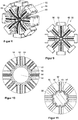
- FIG. 10 An enlarged view of the profile mandrel 60 can be seen, a gap being provided between the profile mandrel 60 and the rollers 52, which gap corresponds to the profile of a shaft to be produced by means of the rolling head 50.
- rollers 52 are profiled and have a roller center profile 53 and a roller edge profile 54.
- the diameter of the roller center profile 53 is larger than the diameter of the roller edge profile 54.
- the rollers 52 and the profile mandrel 60 are arranged with respect to one another such that a roller center profile 53 corresponds to a groove 62 of the profile mandrel 60.
- the roller edge profiles 54 correspond to the profile heads 64 of the profile mandrel 60.
- FIG 11 A cross-section of a detailed view of a rolling head 50 can be seen, the rollers 52 being in contact with an outer shaft 20 which is pushed onto the profile mandrel 60.
- the outer shaft 20 is cold rolled so that the outer shaft 20 takes on the profile of the profile mandrel 60 on its inner peripheral surface and is formed on its outer peripheral surface by the rollers 52 and in particular the roller profile.
- roller center profile 53 corresponds to the groove 52 of the profile mandrel
- the material of the outer shaft 20 is pressed into the groove 62 of the profile mandrel 60 by the roller center profile 53.
- the roller edge profiles 54 roll or roll on the profile heads 24 of the outer shaft 20, which intensifies the force acting on the rollers 52 on the outer shaft 20 and improves the internal toothing of the outer shaft 20 allows.
- the inner shaft of a steering shaft can also be manufactured by means of a roller head described.
- Figures 12 to 14 show the sequence of movements of a double stroke movement for profiling the outer shaft 20. These are cross-sectional views, each showing two opposing rollers 52, a profile mandrel 60 being arranged between the rollers 52, on which an outer shaft 20 is pushed.
- Figure 12 shows a preliminary stroke movement of the profile mandrel 60.
- the profile mandrel 60 is moved relative to the rollers 52. There is no contact between the profile mandrel 60 and the rollers 52, so that the rollers 52 remain in a rest position.
- the outer shaft 20 pushed onto the profile mandrel 60 is in Figure 12 not yet in contact with the rollers 52.
- the in Figure 14 return stroke movement shown.
- the profile mandrel 60 and the outer shaft 20 move together in relation to the forward stroke movement in the opposite direction. There is still contact between the outer shaft 20 and the rollers 52, so that the rollers 52 also rotate in the opposite direction during the return stroke movement.
- the return stroke movement can be maintained until the outer shaft 20 and the profile mandrel 60 have left the roller head 50.
- the return stroke movement can be followed by a new forward stroke movement, for example to improve the quality of the profile of the outer shaft.
- Figure 15 shows a sectional view of the outer shaft 20 and a roller 52, wherein the outer shaft 20 is relative to the roller 52 at a reversal point of the forward stroke movement to the return stroke movement.
- the grooves 22 have the groove length I.
- the roller 52 is continuously rolled along the groove length I from the free end of the shaft 20 to the end of the groove 22. Subsequently, the roller 52 is continuously rolled back from the reversal point at the end of the groove length I. In this way, the complex pipe geometry is created with a very simple rolling process.
Landscapes
- Engineering & Computer Science (AREA)
- Mechanical Engineering (AREA)
- General Engineering & Computer Science (AREA)
- Life Sciences & Earth Sciences (AREA)
- Agronomy & Crop Science (AREA)
- Chemical & Material Sciences (AREA)
- Combustion & Propulsion (AREA)
- Transportation (AREA)
- Ocean & Marine Engineering (AREA)
- Steering Controls (AREA)
- Shafts, Cranks, Connecting Bars, And Related Bearings (AREA)
Claims (7)
- Procédé de production d'un arbre creux profilé pour un arbre de direction télescopique (10) d'un véhicule automobile, comprenant la fourniture d'un arbre creux à usiner ainsi que d'un mandrin profilé (60) et d'une tête de roulage (50) présentant au moins un rouleau (52), le mandrin profilé (60), pour produire une rainure (22, 32) dans l'arbre creux, étant d'abord introduit dans l'arbre creux et ensuite l'arbre creux étant déplacé par rapport à la tête de roulage (50), caractérisé en ce que
pour réaliser une rainure (22, 32), un déplacement de l'arbre creux par rapport à la tête de roulage (50) s'effectue exclusivement dans la direction de l'axe longitudinal de l'arbre creux. - Procédé selon la revendication 1, caractérisé en ce que le mandrin profilé (60) est déplacé conjointement avec l'arbre creux et le déplacement du mandrin profilé (60) et de l'arbre creux par rapport à la tête de roulage (50) s'effectue exclusivement dans la direction de l'axe longitudinal de l'arbre creux.
- Procédé selon l'une quelconque des revendications précédentes, caractérisé en ce que la production de l'au moins une rainure (22, 32) s'effectue avec une longueur de rainure (1) sur l'arbre creux par un mouvement de précourse continu de l'arbre creux par rapport à la tête de roulage (50) le long de la longueur de rainure (1), le rouleau (52) de la tête de roulage (50) roulant sur l'arbre creux dans la direction longitudinale.
- Procédé selon l'une quelconque des revendications précédentes, caractérisé en ce qu'ensuite, l'arbre creux est retiré par rapport à la tête de roulage (50) .
- Procédé selon l'une quelconque des revendications précédentes, caractérisé en ce que la production de toutes les rainures présentes dans l'arbre creux (22, 24, 32, 34) s'effectue dans une étape de travail commune avec un mouvement de précourse continu.
- Procédé de fabrication d'un arbre de direction télescopique (10) pour un véhicule automobile, caractérisé en ce qu'un arbre creux intérieur est introduit avec son profil de rainure dans un arbre creux extérieur avec un profil de rainure, le profil de rainure de l'arbre creux extérieur étant calibré au profil de rainure de l'arbre creux intérieur au moyen d'au moins un rouleau (50) dans un déplacement de précourse continu le long de l'axe longitudinal de l'arbre de direction.
- Procédé selon la revendication 6, caractérisé en ce qu'avant l'introduction de l'arbre creux intérieur dans l'arbre creux extérieur, une douille en plastique est appliquée sur l'arbre creux intérieur, laquelle est disposée entre les arbres creux après l'introduction de l'arbre creux, les trois composants étant calibrés les uns aux autres.
Applications Claiming Priority (2)
| Application Number | Priority Date | Filing Date | Title |
|---|---|---|---|
| DE102014115140 | 2014-10-17 | ||
| PCT/EP2015/067613 WO2016058723A1 (fr) | 2014-10-17 | 2015-07-31 | Arbre de direction et procédé de production d'un arbre creux profilé pour arbre de direction télescopique d'un véhicule automobile |
Publications (2)
| Publication Number | Publication Date |
|---|---|
| EP3206811A1 EP3206811A1 (fr) | 2017-08-23 |
| EP3206811B1 true EP3206811B1 (fr) | 2020-04-22 |
Family
ID=53783710
Family Applications (1)
| Application Number | Title | Priority Date | Filing Date |
|---|---|---|---|
| EP15747433.9A Active EP3206811B1 (fr) | 2014-10-17 | 2015-07-31 | Procédé de production d'un arbre creux profilé pour arbre de direction télescopique d'un véhicule automobile |
Country Status (5)
| Country | Link |
|---|---|
| US (1) | US10948008B2 (fr) |
| EP (1) | EP3206811B1 (fr) |
| CN (1) | CN107074265A (fr) |
| ES (1) | ES2805098T3 (fr) |
| WO (1) | WO2016058723A1 (fr) |
Families Citing this family (14)
| Publication number | Priority date | Publication date | Assignee | Title |
|---|---|---|---|---|
| DE102016114970A1 (de) * | 2016-08-11 | 2018-02-15 | Thyssenkrupp Ag | Lenkwelle für ein Kraftfahrzeug |
| DE102016215023B4 (de) * | 2016-08-11 | 2023-02-02 | Thyssenkrupp Ag | Verfahren zur Herstellung einer längenveränderbaren Lenkwelle und längenveränderbare Lenkwelle |
| CN108246941A (zh) * | 2016-12-29 | 2018-07-06 | 财团法人金属工业研究发展中心 | 齿轮的成型装置及其制造方法 |
| DE102017114534A1 (de) | 2017-06-29 | 2019-01-03 | Thyssenkrupp Ag | Lenkwelle für ein Kraftfahrzeug und Verfahren zum Herstellen |
| FR3070459B1 (fr) * | 2017-08-30 | 2020-02-21 | Robert Bosch Automotive Steering Vendome | Arbre intermediaire telescopique pour transmission de direction et son procede de fabrication |
| US11009078B2 (en) * | 2018-04-24 | 2021-05-18 | Textron Innovations Inc. | Compressible driveshaft |
| KR102174259B1 (ko) * | 2018-09-28 | 2020-11-04 | 일진제강(주) | 업세팅 공법을 이용한 중공 드라이브 샤프트 및 이의 제조 방법 |
| DE102018127098B3 (de) * | 2018-10-30 | 2019-11-21 | Thyssenkrupp Ag | Lenkwelle für eine Lenksäule eines Kraftfahrzeugs und Lenksäule für ein Kraftfahrzeug |
| DE102019207525A1 (de) * | 2019-05-22 | 2020-11-26 | Thyssenkrupp Ag | Lenksäule für ein Kraftfahrzeug |
| US11591003B2 (en) | 2020-10-01 | 2023-02-28 | Thyssenkrupp Presta Ag | Stowable steering column |
| US11318981B1 (en) | 2020-10-29 | 2022-05-03 | Thyssenkrupp Presta Ag | Stowable steering column |
| CN112588859A (zh) * | 2020-11-30 | 2021-04-02 | 思睿观通科技(江苏)有限公司 | 一种金属制品成型设备 |
| CN114810845A (zh) * | 2022-04-28 | 2022-07-29 | 洛阳轴承研究所有限公司 | 一种可实现传动侧向间隙自消除的花键传动装置 |
| CN115013451A (zh) * | 2022-06-27 | 2022-09-06 | 诸暨市双普机械有限公司 | 一种用于座驾式抹光机的万向连轴器 |
Family Cites Families (38)
| Publication number | Priority date | Publication date | Assignee | Title |
|---|---|---|---|---|
| US531170A (en) * | 1894-12-18 | Emil h | ||
| US473020A (en) * | 1892-04-19 | Method of corrugating pipes | ||
| US10569A (en) * | 1854-02-28 | jackson | ||
| US14551A (en) * | 1856-04-01 | Seamless metal tubes | ||
| US1605828A (en) * | 1926-11-02 | Pluting machine | ||
| US838569A (en) * | 1906-05-21 | 1906-12-18 | Isaac W Numan | Corrugating-machine. |
| US890526A (en) * | 1906-12-18 | 1908-06-09 | Union Metal Post Company | Corrugating-machine. |
| US1638481A (en) * | 1926-09-09 | 1927-08-09 | Union Metal Mfg Co | Fluting machine |
| US2367226A (en) * | 1940-05-10 | 1945-01-16 | Foster Wheeler Corp | Apparatus for producing extended surface tubular members |
| GB914329A (fr) | 1958-01-13 | |||
| FR1331015A (fr) * | 1962-08-03 | 1963-06-28 | élément tubulaire de transmission à cannelures axiales et son procédé d'exécution | |
| US3330145A (en) * | 1964-10-05 | 1967-07-11 | Straza Ind | Machine and method for tapering rodlike tubular workpieces |
| GB1142837A (en) * | 1966-11-09 | 1969-02-12 | Exnii Metallorezh Stankov | Improvements in or relating to pressure heads |
| JPS4834663B1 (fr) * | 1968-06-26 | 1973-10-23 | ||
| DE2017709A1 (de) | 1970-04-14 | 1971-11-04 | Zahnradfabrik Friedrichshafen Ag, 7990 Friedrichshafen | Werkzeug zum Einrollen von Längsnuten in zylindrische Werkstücke |
| CH579427A5 (fr) | 1975-02-24 | 1976-09-15 | Grob Ernst Fa | |
| IT1129074B (it) | 1980-04-16 | 1986-06-04 | Metalli Ind Spa | Apparecchiatura per formare a punta l estremita di un tubo metallico mediante un operazione di trafilatura |
| JPS577317A (en) * | 1980-06-17 | 1982-01-14 | Sumitomo Light Metal Ind Ltd | Manufacture of grooved pipe |
| AT372314B (de) | 1981-07-03 | 1983-09-26 | Supervis Ets | Lenkspindel fuer lenkvorrichtungen bei kraftfahrzeugen |
| JPS5835023A (ja) * | 1981-08-26 | 1983-03-01 | Masaru Onishi | 管材の溝部形成方法 |
| GB8605769D0 (en) | 1986-03-08 | 1986-04-16 | Brd Co Ltd | Propeller shaft for motor vehicle |
| CH675840A5 (fr) * | 1988-10-05 | 1990-11-15 | Grob Ernst Fa | |
| US4995252A (en) * | 1989-03-06 | 1991-02-26 | Carrier Corporation | Method and apparatus for internally enhancing heat exchanger tubing |
| US5231859A (en) * | 1992-03-03 | 1993-08-03 | Trimble House Corporation | Fluting machine |
| US5765419A (en) * | 1994-06-25 | 1998-06-16 | Ernst Grob Ag | Method and apparatus for a rolling of hollow articles |
| JPH10314837A (ja) * | 1997-03-12 | 1998-12-02 | Nisshin Steel Co Ltd | 螺旋状異形管及びその成形方法並びに成形装置 |
| JPH1190510A (ja) * | 1997-09-19 | 1999-04-06 | Plant Engineering Yoshida Kinen Kk | 線材の圧延装置 |
| US6754943B1 (en) * | 1998-12-31 | 2004-06-29 | Torque-Traction Technologies, Inc. | Method of manufacturing an axially collapsible driveshaft assembly |
| US6705949B2 (en) | 2001-08-27 | 2004-03-16 | Visteon Global Technologies, Inc. | Shaft spline having a straight side tooth profile |
| DE10317506C5 (de) | 2003-04-16 | 2008-05-15 | Daimler Ag | Verfahren zum Herstellen eines hohlen Werkstücks und nach dem Verfahren hergestelltes hohles Werkstück |
| CA2557640C (fr) * | 2004-02-19 | 2012-04-24 | Ernst Grob Ag | Profil de dent d'un arbre cannele |
| WO2005094293A2 (fr) * | 2004-03-26 | 2005-10-13 | Victaulic Company Of America | Outil a molettes servant a realiser des rainures dans des tuyaux |
| CA2573677C (fr) | 2004-07-12 | 2012-03-20 | Packless Metal Hose, Inc. | Procede et appareil de formation d'une conduite modifiee |
| JP2007032681A (ja) * | 2005-07-26 | 2007-02-08 | Jtekt Corp | 伸縮自在シャフトおよび車両操舵用伸縮自在シャフト |
| US8113027B2 (en) * | 2008-04-23 | 2012-02-14 | Illinois Tool Works Inc. | Method and device for the manufacture of multiple grooved wire |
| DE102008049825B4 (de) * | 2008-10-01 | 2017-04-06 | Thyssenkrupp Presta Aktiengesellschaft | Gleithülse |
| DE102014017407A1 (de) * | 2014-11-26 | 2016-06-02 | Thyssenkrupp Ag | Verfahren zur Herstellung einer profilierten Hohlwelle für eine teleskopierbare Lenkwelle und teleskopierbare Lenkwelle |
| US20170058940A1 (en) * | 2015-08-26 | 2017-03-02 | Neapco Drivelines, Llc | Radial pilot for slip-in-tube driveshaft |
-
2015
- 2015-07-31 US US15/519,751 patent/US10948008B2/en active Active
- 2015-07-31 ES ES15747433T patent/ES2805098T3/es active Active
- 2015-07-31 CN CN201580055953.0A patent/CN107074265A/zh active Pending
- 2015-07-31 WO PCT/EP2015/067613 patent/WO2016058723A1/fr not_active Ceased
- 2015-07-31 EP EP15747433.9A patent/EP3206811B1/fr active Active
Non-Patent Citations (1)
| Title |
|---|
| None * |
Also Published As
| Publication number | Publication date |
|---|---|
| ES2805098T3 (es) | 2021-02-10 |
| EP3206811A1 (fr) | 2017-08-23 |
| WO2016058723A1 (fr) | 2016-04-21 |
| US10948008B2 (en) | 2021-03-16 |
| US20170241472A1 (en) | 2017-08-24 |
| CN107074265A (zh) | 2017-08-18 |
Similar Documents
| Publication | Publication Date | Title |
|---|---|---|
| EP3206811B1 (fr) | Procédé de production d'un arbre creux profilé pour arbre de direction télescopique d'un véhicule automobile | |
| EP2467231B1 (fr) | Procédé de fabrication d'un élément de colonne de direction formant une section d'une colonne de direction | |
| WO2016082969A1 (fr) | Procédé de fabrication d'un arbre creux profilé pour un arbre de direction télescopique et arbre de direction télescopique | |
| EP1989011B1 (fr) | Procede de fabrication d'une piece de colonne de direction et colonne de direction dotee de cette piece de colonne de direction | |
| DE102009045857A1 (de) | Verfahren zur Herstellung einer Spindel für einen Spindeltrieb, Wälzgewindetrieb mit einer solchen Spindel und Verwendung des Wälzgewindetriebs | |
| WO2018024701A1 (fr) | Procédé de fabrication d'un élément d'une colonne de direction et colonne de direction de véhicule automobile | |
| EP3496993B1 (fr) | Procédé de manufacture d'un arbre de direction ajustable en longueur et un axe de direction ajustable en longueur | |
| EP2731850B1 (fr) | Pignon de direction pour un système de direction et procédé pour sa fabrication | |
| DE3874636T2 (de) | Verfahren und vorrichtung zum formen durch haemmern eines wellenrohres und seine anwendung bei rohren der automobilindustrie. | |
| EP1356891B1 (fr) | Procédé de fabrication de manchons coulissants pour boítes de vitesses | |
| DE102012112890B3 (de) | Lenksäule für ein Kraftfahrzeug | |
| EP2167254B1 (fr) | Procédé de fabrication d'un moyeu selon un procédé d'emboutissage au moyen d'au moins un cylindre d'emboutissage rotatif | |
| EP4306263A1 (fr) | Procédé de fabrication d'une tige coulissante pour une direction de véhicule automobile | |
| EP3840898A1 (fr) | Colonne de direction pour véhicule et procédé pour sa fabrication | |
| DE10317506C5 (de) | Verfahren zum Herstellen eines hohlen Werkstücks und nach dem Verfahren hergestelltes hohles Werkstück | |
| DE102008045728C5 (de) | Walzstange | |
| DE102020203101A1 (de) | Verfahren zur Herstellung eines Lenkwellenteils einer Lenkwelle für ein Kraftfahrzeug, Verfahren zur Herstellung einer Lenkwelle für ein Kraftfahrzeug, Lenkwellenteil für eine Lenkwelle für ein Kraftfahrzeug, Lenkwelle für ein Kraftfahrzeug und Lenksäule für ein Kraftfahrzeug | |
| DE3822640C2 (fr) | ||
| DE102021201652A1 (de) | Verfahren zur Herstellung einer Zahnstange für ein Lenkgetriebe eines Kraftfahrzeugs, Zahnstange für ein Lenkgetriebe eines Kraftfahrzeugs und Lenkgetriebe für ein Kraftfahrzeug | |
| DE102004014506B4 (de) | Verfahren zur Herstellung eines Teleskopmechanismus | |
| CH670782A5 (fr) | ||
| EP4323132B1 (fr) | Procédé de production d'un composant avec un profil de denture, et outil | |
| EP2780126B1 (fr) | Procédé et dispositif de fabrication de profils dotés d'une déformation variable selon la position et orientée en longueur | |
| DE102006048304A1 (de) | Lenkgetriebe für ein Fahrzeug | |
| DE102004018209A1 (de) | Welle mit einem als Außen-N-Rund ausgebildeten Befestigungsabschnitt und Verfahren zur Herstellung solch einer Welle |
Legal Events
| Date | Code | Title | Description |
|---|---|---|---|
| STAA | Information on the status of an ep patent application or granted ep patent |
Free format text: STATUS: THE INTERNATIONAL PUBLICATION HAS BEEN MADE |
|
| PUAI | Public reference made under article 153(3) epc to a published international application that has entered the european phase |
Free format text: ORIGINAL CODE: 0009012 |
|
| STAA | Information on the status of an ep patent application or granted ep patent |
Free format text: STATUS: REQUEST FOR EXAMINATION WAS MADE |
|
| 17P | Request for examination filed |
Effective date: 20170328 |
|
| AK | Designated contracting states |
Kind code of ref document: A1 Designated state(s): AL AT BE BG CH CY CZ DE DK EE ES FI FR GB GR HR HU IE IS IT LI LT LU LV MC MK MT NL NO PL PT RO RS SE SI SK SM TR |
|
| AX | Request for extension of the european patent |
Extension state: BA ME |
|
| DAV | Request for validation of the european patent (deleted) | ||
| DAX | Request for extension of the european patent (deleted) | ||
| GRAP | Despatch of communication of intention to grant a patent |
Free format text: ORIGINAL CODE: EPIDOSNIGR1 |
|
| STAA | Information on the status of an ep patent application or granted ep patent |
Free format text: STATUS: GRANT OF PATENT IS INTENDED |
|
| INTG | Intention to grant announced |
Effective date: 20200103 |
|
| RAP1 | Party data changed (applicant data changed or rights of an application transferred) |
Owner name: THYSSENKRUPP PRESTA AG Owner name: THYSSENKRUPP AG |
|
| RIN1 | Information on inventor provided before grant (corrected) |
Inventor name: WALSER, MICHAEL |
|
| GRAS | Grant fee paid |
Free format text: ORIGINAL CODE: EPIDOSNIGR3 |
|
| GRAA | (expected) grant |
Free format text: ORIGINAL CODE: 0009210 |
|
| STAA | Information on the status of an ep patent application or granted ep patent |
Free format text: STATUS: THE PATENT HAS BEEN GRANTED |
|
| AK | Designated contracting states |
Kind code of ref document: B1 Designated state(s): AL AT BE BG CH CY CZ DE DK EE ES FI FR GB GR HR HU IE IS IT LI LT LU LV MC MK MT NL NO PL PT RO RS SE SI SK SM TR |
|
| REG | Reference to a national code |
Ref country code: CH Ref legal event code: EP |
|
| REG | Reference to a national code |
Ref country code: IE Ref legal event code: FG4D Free format text: LANGUAGE OF EP DOCUMENT: GERMAN |
|
| REG | Reference to a national code |
Ref country code: DE Ref legal event code: R096 Ref document number: 502015012364 Country of ref document: DE |
|
| REG | Reference to a national code |
Ref country code: AT Ref legal event code: REF Ref document number: 1259407 Country of ref document: AT Kind code of ref document: T Effective date: 20200515 |
|
| REG | Reference to a national code |
Ref country code: LT Ref legal event code: MG4D |
|
| REG | Reference to a national code |
Ref country code: NL Ref legal event code: MP Effective date: 20200422 |
|
| PG25 | Lapsed in a contracting state [announced via postgrant information from national office to epo] |
Ref country code: NL Free format text: LAPSE BECAUSE OF FAILURE TO SUBMIT A TRANSLATION OF THE DESCRIPTION OR TO PAY THE FEE WITHIN THE PRESCRIBED TIME-LIMIT Effective date: 20200422 Ref country code: NO Free format text: LAPSE BECAUSE OF FAILURE TO SUBMIT A TRANSLATION OF THE DESCRIPTION OR TO PAY THE FEE WITHIN THE PRESCRIBED TIME-LIMIT Effective date: 20200722 Ref country code: GR Free format text: LAPSE BECAUSE OF FAILURE TO SUBMIT A TRANSLATION OF THE DESCRIPTION OR TO PAY THE FEE WITHIN THE PRESCRIBED TIME-LIMIT Effective date: 20200723 Ref country code: PT Free format text: LAPSE BECAUSE OF FAILURE TO SUBMIT A TRANSLATION OF THE DESCRIPTION OR TO PAY THE FEE WITHIN THE PRESCRIBED TIME-LIMIT Effective date: 20200824 Ref country code: LT Free format text: LAPSE BECAUSE OF FAILURE TO SUBMIT A TRANSLATION OF THE DESCRIPTION OR TO PAY THE FEE WITHIN THE PRESCRIBED TIME-LIMIT Effective date: 20200422 Ref country code: FI Free format text: LAPSE BECAUSE OF FAILURE TO SUBMIT A TRANSLATION OF THE DESCRIPTION OR TO PAY THE FEE WITHIN THE PRESCRIBED TIME-LIMIT Effective date: 20200422 Ref country code: IS Free format text: LAPSE BECAUSE OF FAILURE TO SUBMIT A TRANSLATION OF THE DESCRIPTION OR TO PAY THE FEE WITHIN THE PRESCRIBED TIME-LIMIT Effective date: 20200822 Ref country code: SE Free format text: LAPSE BECAUSE OF FAILURE TO SUBMIT A TRANSLATION OF THE DESCRIPTION OR TO PAY THE FEE WITHIN THE PRESCRIBED TIME-LIMIT Effective date: 20200422 |
|
| PG25 | Lapsed in a contracting state [announced via postgrant information from national office to epo] |
Ref country code: BG Free format text: LAPSE BECAUSE OF FAILURE TO SUBMIT A TRANSLATION OF THE DESCRIPTION OR TO PAY THE FEE WITHIN THE PRESCRIBED TIME-LIMIT Effective date: 20200722 Ref country code: RS Free format text: LAPSE BECAUSE OF FAILURE TO SUBMIT A TRANSLATION OF THE DESCRIPTION OR TO PAY THE FEE WITHIN THE PRESCRIBED TIME-LIMIT Effective date: 20200422 Ref country code: LV Free format text: LAPSE BECAUSE OF FAILURE TO SUBMIT A TRANSLATION OF THE DESCRIPTION OR TO PAY THE FEE WITHIN THE PRESCRIBED TIME-LIMIT Effective date: 20200422 Ref country code: HR Free format text: LAPSE BECAUSE OF FAILURE TO SUBMIT A TRANSLATION OF THE DESCRIPTION OR TO PAY THE FEE WITHIN THE PRESCRIBED TIME-LIMIT Effective date: 20200422 |
|
| PG25 | Lapsed in a contracting state [announced via postgrant information from national office to epo] |
Ref country code: AL Free format text: LAPSE BECAUSE OF FAILURE TO SUBMIT A TRANSLATION OF THE DESCRIPTION OR TO PAY THE FEE WITHIN THE PRESCRIBED TIME-LIMIT Effective date: 20200422 |
|
| REG | Reference to a national code |
Ref country code: DE Ref legal event code: R097 Ref document number: 502015012364 Country of ref document: DE |
|
| PG25 | Lapsed in a contracting state [announced via postgrant information from national office to epo] |
Ref country code: SM Free format text: LAPSE BECAUSE OF FAILURE TO SUBMIT A TRANSLATION OF THE DESCRIPTION OR TO PAY THE FEE WITHIN THE PRESCRIBED TIME-LIMIT Effective date: 20200422 Ref country code: DK Free format text: LAPSE BECAUSE OF FAILURE TO SUBMIT A TRANSLATION OF THE DESCRIPTION OR TO PAY THE FEE WITHIN THE PRESCRIBED TIME-LIMIT Effective date: 20200422 Ref country code: RO Free format text: LAPSE BECAUSE OF FAILURE TO SUBMIT A TRANSLATION OF THE DESCRIPTION OR TO PAY THE FEE WITHIN THE PRESCRIBED TIME-LIMIT Effective date: 20200422 Ref country code: EE Free format text: LAPSE BECAUSE OF FAILURE TO SUBMIT A TRANSLATION OF THE DESCRIPTION OR TO PAY THE FEE WITHIN THE PRESCRIBED TIME-LIMIT Effective date: 20200422 |
|
| REG | Reference to a national code |
Ref country code: ES Ref legal event code: FG2A Ref document number: 2805098 Country of ref document: ES Kind code of ref document: T3 Effective date: 20210210 |
|
| PG25 | Lapsed in a contracting state [announced via postgrant information from national office to epo] |
Ref country code: PL Free format text: LAPSE BECAUSE OF FAILURE TO SUBMIT A TRANSLATION OF THE DESCRIPTION OR TO PAY THE FEE WITHIN THE PRESCRIBED TIME-LIMIT Effective date: 20200422 Ref country code: MC Free format text: LAPSE BECAUSE OF FAILURE TO SUBMIT A TRANSLATION OF THE DESCRIPTION OR TO PAY THE FEE WITHIN THE PRESCRIBED TIME-LIMIT Effective date: 20200422 Ref country code: SK Free format text: LAPSE BECAUSE OF FAILURE TO SUBMIT A TRANSLATION OF THE DESCRIPTION OR TO PAY THE FEE WITHIN THE PRESCRIBED TIME-LIMIT Effective date: 20200422 |
|
| PLBE | No opposition filed within time limit |
Free format text: ORIGINAL CODE: 0009261 |
|
| REG | Reference to a national code |
Ref country code: CH Ref legal event code: PL |
|
| STAA | Information on the status of an ep patent application or granted ep patent |
Free format text: STATUS: NO OPPOSITION FILED WITHIN TIME LIMIT |
|
| 26N | No opposition filed |
Effective date: 20210125 |
|
| REG | Reference to a national code |
Ref country code: BE Ref legal event code: MM Effective date: 20200731 |
|
| PG25 | Lapsed in a contracting state [announced via postgrant information from national office to epo] |
Ref country code: LI Free format text: LAPSE BECAUSE OF NON-PAYMENT OF DUE FEES Effective date: 20200731 Ref country code: LU Free format text: LAPSE BECAUSE OF NON-PAYMENT OF DUE FEES Effective date: 20200731 Ref country code: CH Free format text: LAPSE BECAUSE OF NON-PAYMENT OF DUE FEES Effective date: 20200731 |
|
| PG25 | Lapsed in a contracting state [announced via postgrant information from national office to epo] |
Ref country code: BE Free format text: LAPSE BECAUSE OF NON-PAYMENT OF DUE FEES Effective date: 20200731 Ref country code: SI Free format text: LAPSE BECAUSE OF FAILURE TO SUBMIT A TRANSLATION OF THE DESCRIPTION OR TO PAY THE FEE WITHIN THE PRESCRIBED TIME-LIMIT Effective date: 20200422 |
|
| PG25 | Lapsed in a contracting state [announced via postgrant information from national office to epo] |
Ref country code: IE Free format text: LAPSE BECAUSE OF NON-PAYMENT OF DUE FEES Effective date: 20200731 |
|
| REG | Reference to a national code |
Ref country code: AT Ref legal event code: MM01 Ref document number: 1259407 Country of ref document: AT Kind code of ref document: T Effective date: 20200731 |
|
| PG25 | Lapsed in a contracting state [announced via postgrant information from national office to epo] |
Ref country code: AT Free format text: LAPSE BECAUSE OF NON-PAYMENT OF DUE FEES Effective date: 20200731 |
|
| PG25 | Lapsed in a contracting state [announced via postgrant information from national office to epo] |
Ref country code: TR Free format text: LAPSE BECAUSE OF FAILURE TO SUBMIT A TRANSLATION OF THE DESCRIPTION OR TO PAY THE FEE WITHIN THE PRESCRIBED TIME-LIMIT Effective date: 20200422 Ref country code: MT Free format text: LAPSE BECAUSE OF FAILURE TO SUBMIT A TRANSLATION OF THE DESCRIPTION OR TO PAY THE FEE WITHIN THE PRESCRIBED TIME-LIMIT Effective date: 20200422 Ref country code: CY Free format text: LAPSE BECAUSE OF FAILURE TO SUBMIT A TRANSLATION OF THE DESCRIPTION OR TO PAY THE FEE WITHIN THE PRESCRIBED TIME-LIMIT Effective date: 20200422 |
|
| PG25 | Lapsed in a contracting state [announced via postgrant information from national office to epo] |
Ref country code: MK Free format text: LAPSE BECAUSE OF FAILURE TO SUBMIT A TRANSLATION OF THE DESCRIPTION OR TO PAY THE FEE WITHIN THE PRESCRIBED TIME-LIMIT Effective date: 20200422 |
|
| REG | Reference to a national code |
Ref country code: DE Ref legal event code: R084 Ref document number: 502015012364 Country of ref document: DE |
|
| PGFP | Annual fee paid to national office [announced via postgrant information from national office to epo] |
Ref country code: IT Payment date: 20220726 Year of fee payment: 8 Ref country code: ES Payment date: 20220928 Year of fee payment: 8 Ref country code: CZ Payment date: 20220728 Year of fee payment: 8 |
|
| PG25 | Lapsed in a contracting state [announced via postgrant information from national office to epo] |
Ref country code: CZ Free format text: LAPSE BECAUSE OF NON-PAYMENT OF DUE FEES Effective date: 20230731 |
|
| PG25 | Lapsed in a contracting state [announced via postgrant information from national office to epo] |
Ref country code: IT Free format text: LAPSE BECAUSE OF NON-PAYMENT OF DUE FEES Effective date: 20230731 |
|
| REG | Reference to a national code |
Ref country code: ES Ref legal event code: FD2A Effective date: 20240903 |
|
| PG25 | Lapsed in a contracting state [announced via postgrant information from national office to epo] |
Ref country code: ES Free format text: LAPSE BECAUSE OF NON-PAYMENT OF DUE FEES Effective date: 20230801 |
|
| PG25 | Lapsed in a contracting state [announced via postgrant information from national office to epo] |
Ref country code: ES Free format text: LAPSE BECAUSE OF NON-PAYMENT OF DUE FEES Effective date: 20230801 |
|
| PGFP | Annual fee paid to national office [announced via postgrant information from national office to epo] |
Ref country code: DE Payment date: 20250722 Year of fee payment: 11 |
|
| PGFP | Annual fee paid to national office [announced via postgrant information from national office to epo] |
Ref country code: GB Payment date: 20250722 Year of fee payment: 11 |
|
| PGFP | Annual fee paid to national office [announced via postgrant information from national office to epo] |
Ref country code: FR Payment date: 20250725 Year of fee payment: 11 |