EP3206885B1 - Sicherheitselement für ein sicherheitsdokument - Google Patents
Sicherheitselement für ein sicherheitsdokument Download PDFInfo
- Publication number
- EP3206885B1 EP3206885B1 EP15784595.9A EP15784595A EP3206885B1 EP 3206885 B1 EP3206885 B1 EP 3206885B1 EP 15784595 A EP15784595 A EP 15784595A EP 3206885 B1 EP3206885 B1 EP 3206885B1
- Authority
- EP
- European Patent Office
- Prior art keywords
- layer
- security
- pattern
- masking layer
- notably
- Prior art date
- Legal status (The legal status is an assumption and is not a legal conclusion. Google has not performed a legal analysis and makes no representation as to the accuracy of the status listed.)
- Revoked
Links
Images

Classifications
-
- B—PERFORMING OPERATIONS; TRANSPORTING
- B42—BOOKBINDING; ALBUMS; FILES; SPECIAL PRINTED MATTER
- B42D—BOOKS; BOOK COVERS; LOOSE LEAVES; PRINTED MATTER CHARACTERISED BY IDENTIFICATION OR SECURITY FEATURES; PRINTED MATTER OF SPECIAL FORMAT OR STYLE NOT OTHERWISE PROVIDED FOR; DEVICES FOR USE THEREWITH AND NOT OTHERWISE PROVIDED FOR; MOVABLE-STRIP WRITING OR READING APPARATUS
- B42D25/00—Information-bearing cards or sheet-like structures characterised by identification or security features; Manufacture thereof
- B42D25/30—Identification or security features, e.g. for preventing forgery
- B42D25/36—Identification or security features, e.g. for preventing forgery comprising special materials
- B42D25/373—Metallic materials
-
- B—PERFORMING OPERATIONS; TRANSPORTING
- B42—BOOKBINDING; ALBUMS; FILES; SPECIAL PRINTED MATTER
- B42D—BOOKS; BOOK COVERS; LOOSE LEAVES; PRINTED MATTER CHARACTERISED BY IDENTIFICATION OR SECURITY FEATURES; PRINTED MATTER OF SPECIAL FORMAT OR STYLE NOT OTHERWISE PROVIDED FOR; DEVICES FOR USE THEREWITH AND NOT OTHERWISE PROVIDED FOR; MOVABLE-STRIP WRITING OR READING APPARATUS
- B42D25/00—Information-bearing cards or sheet-like structures characterised by identification or security features; Manufacture thereof
- B42D25/30—Identification or security features, e.g. for preventing forgery
- B42D25/351—Translucent or partly translucent parts, e.g. windows
-
- B—PERFORMING OPERATIONS; TRANSPORTING
- B42—BOOKBINDING; ALBUMS; FILES; SPECIAL PRINTED MATTER
- B42D—BOOKS; BOOK COVERS; LOOSE LEAVES; PRINTED MATTER CHARACTERISED BY IDENTIFICATION OR SECURITY FEATURES; PRINTED MATTER OF SPECIAL FORMAT OR STYLE NOT OTHERWISE PROVIDED FOR; DEVICES FOR USE THEREWITH AND NOT OTHERWISE PROVIDED FOR; MOVABLE-STRIP WRITING OR READING APPARATUS
- B42D25/00—Information-bearing cards or sheet-like structures characterised by identification or security features; Manufacture thereof
- B42D25/30—Identification or security features, e.g. for preventing forgery
- B42D25/355—Security threads
-
- B—PERFORMING OPERATIONS; TRANSPORTING
- B42—BOOKBINDING; ALBUMS; FILES; SPECIAL PRINTED MATTER
- B42D—BOOKS; BOOK COVERS; LOOSE LEAVES; PRINTED MATTER CHARACTERISED BY IDENTIFICATION OR SECURITY FEATURES; PRINTED MATTER OF SPECIAL FORMAT OR STYLE NOT OTHERWISE PROVIDED FOR; DEVICES FOR USE THEREWITH AND NOT OTHERWISE PROVIDED FOR; MOVABLE-STRIP WRITING OR READING APPARATUS
- B42D25/00—Information-bearing cards or sheet-like structures characterised by identification or security features; Manufacture thereof
- B42D25/30—Identification or security features, e.g. for preventing forgery
- B42D25/36—Identification or security features, e.g. for preventing forgery comprising special materials
- B42D25/369—Magnetised or magnetisable materials
-
- B—PERFORMING OPERATIONS; TRANSPORTING
- B42—BOOKBINDING; ALBUMS; FILES; SPECIAL PRINTED MATTER
- B42D—BOOKS; BOOK COVERS; LOOSE LEAVES; PRINTED MATTER CHARACTERISED BY IDENTIFICATION OR SECURITY FEATURES; PRINTED MATTER OF SPECIAL FORMAT OR STYLE NOT OTHERWISE PROVIDED FOR; DEVICES FOR USE THEREWITH AND NOT OTHERWISE PROVIDED FOR; MOVABLE-STRIP WRITING OR READING APPARATUS
- B42D25/00—Information-bearing cards or sheet-like structures characterised by identification or security features; Manufacture thereof
- B42D25/30—Identification or security features, e.g. for preventing forgery
- B42D25/36—Identification or security features, e.g. for preventing forgery comprising special materials
- B42D25/378—Special inks
-
- B—PERFORMING OPERATIONS; TRANSPORTING
- B42—BOOKBINDING; ALBUMS; FILES; SPECIAL PRINTED MATTER
- B42D—BOOKS; BOOK COVERS; LOOSE LEAVES; PRINTED MATTER CHARACTERISED BY IDENTIFICATION OR SECURITY FEATURES; PRINTED MATTER OF SPECIAL FORMAT OR STYLE NOT OTHERWISE PROVIDED FOR; DEVICES FOR USE THEREWITH AND NOT OTHERWISE PROVIDED FOR; MOVABLE-STRIP WRITING OR READING APPARATUS
- B42D25/00—Information-bearing cards or sheet-like structures characterised by identification or security features; Manufacture thereof
- B42D25/30—Identification or security features, e.g. for preventing forgery
- B42D25/36—Identification or security features, e.g. for preventing forgery comprising special materials
- B42D25/378—Special inks
- B42D25/387—Special inks absorbing or reflecting ultraviolet light
Definitions
- the present invention relates to security elements for secure documents.
- the invention relates more particularly to security elements comprising an at least partially transparent support and security structures carried by this support to reveal patterns when the element is observed in transmitted light or in reflection.
- security element security wires constituted by a strip of a transparent thermoplastic material coated on one face with at least one metal deposit with openings formed by demetallization, showing patterns when the element is observed in transmitted light, such security is also called CLEARTEXT.
- WO 2009/053673 discloses such a security feature.
- This document describes a security thread comprising a support provided with an openwork opaque metal layer defining a pattern, this layer being coated with a diffusing layer deposited in the form of a pattern.
- the appearance of the wire is substantially the same as in the absence of a diffusing layer.
- the pattern of the diffusing layer may appear.
- the diffusing layer comprises magnetic particles
- the magnetic signal is relatively weak because the concentration of magnetic particles must be low to maintain the invisibility in transmitted light of the diffusing layer and thus not to disturb the observation in transmitted light of the CLEARTEXT.
- the patent application US 2012/0025514 relates to a security element comprising two separate superimposed patterns.
- the security element comprises an at least partially transparent substrate, on the front and back of which appear first and second marks in the form of metallizations and / or prints, the first marks mainly being superimposed on the second marks, the first and second marks respectively forming first and second distinct patterns on their respective faces, the degree of visibility of the second marks varying with the angle of observation of the front of the security element.
- WO 2009/149831 discloses a security element comprising at least one multilayer structure, which can create interference, consisting of at least one reflective layer comprising holes, at least one partial transmission layer comprising at least one patterned hole and at least one layer dielectric disposed between these two layers.
- WO 2013/050140 describes a security element comprising a coating made of a material having an optically variable effect and comprising empty spaces detectable in transmitted light, the security element comprising a substrate and a partial layer with empty spaces.
- the partial layer is formed of an opaque coating which has light absorption properties on the side facing the coating made of the material with optically variable effect.
- the partial opaque layer has a metallic tint on the side opposite that which faces the coating made of the material having an optically variable effect.
- the partially opaque coating consists of a metallic layer absorbing light and a reflective metallic layer.
- Requirement WO 99/04983 relates to a security element for protecting objects, comprising at least one magnetic layer that can be tested mechanically and at least one other layer comprising a partially transparent layer in the visual spectral range The partially transparent layer is arranged on the magnetic layer so as to cover the latter.
- the invention aims to further improve the security elements, in order to provide in particular a visible effect in transmitted light and a distinct effect visible in reflection, without excessively complicating their manufacture.
- the object of the invention is therefore, according to a first of its aspects, a security element for a secure document as defined in claim 1.
- the invention makes it possible to have at least one item of information, in particular said second pattern, visible on only one side of the element, in reflected light, in particular on the back side thanks to the pattern layer.
- the invention makes it possible to achieve, if desired, level 1 security revealing to the naked eye and in white light different patterns in transmitted light and in reflection.
- a non-diffusing and non-opaque pattern layer is advantageous in that it makes it possible to obtain a visual contrast showing a pattern in reflected light, while retaining a relatively transparent appearance in transmitted light, not disturbing excessively the visibility of the visible pattern in transmitted light.
- the non-diffusing pattern layer is preferably formed from an impression of a dye ink, in particular devoid of particulate charges the size of which is greater than 50 nm, preferably totally devoid of particulate charges.
- the non-diffusing pattern layer is formed from a semi-transparent metal deposit.
- the size of the particulate charges is in particular the size D 90 , for example in number, and it is preferably the largest dimension.
- the element can comprise a magnetic layer covered at least partially by the masking layer.
- This magnetic layer can be discontinuous.
- the element may include a metallic intermediate layer between the masking layer and the magnetic layer, making it possible to further reduce the visibility in reflected light of the magnetic layer, the intermediate layer preferably being formed of a reflective metal.
- the metallic intermediate layer can be discontinuous.
- the first structure can be formed of a metal layer selectively present on the substrate, in particular with openings defining the first pattern (s).
- the masking layer is diffusing, and includes a pigment filler.
- the masking layer then comprises a mixture of at least two nanometric charges with different refractive indices.
- the masking layer can be white.
- the masking layer is semi-transparent metallic, in particular thin metallic and / or woven metallic.
- the masking layer can extend continuously.
- the masking layer can cover more than 50% of the face of the support that it covers, better more than 75%, even better 100%.
- the pattern layer can cover less than 100% of the masking layer, better still less than 50%.
- the first and second structures are preferably arranged on opposite faces of the support.
- the pattern layer may be substantially transparent to UV radiation at 365 nm, which makes it possible not to affect the way in which one or more possible additional security means, carried by the security element or the document, react.
- the support may include, in particular be constituted by, a film of transparent thermoplastic material, preferably PET.
- the element can be in the form of a security thread.
- the different appearance of the front and back sides can facilitate the manufacture of documents incorporating the element, constituting a visual reference very easy to discern during the insertion of the element and its control.
- At least partially transparent support it should be understood that there is at least one region of the support which is sufficiently transparent or translucent for the first pattern of light transmitted through the security element to be observed.
- non-opaque masking layer By “non-opaque masking layer”, it should be understood that the layer allows white light to pass under certain observation conditions at least, with a transmission factor preferably of at least 10%, better still at least 20%. measured according to ISO 15368. We also speak of semi-transparency.
- non-diffusing pattern layer has a transmittance measured according to ISO standard 15368 using a goniospectrophotometer equal to 0 at an angle different from 0 ° ⁇ 2 ° and different from 0 at an angle equal to 0 ° ⁇ 2 °.
- the semi-transparent nature of the masking layer can be independent of the angle of observation, which is for example the case for a deposit of metal of homogeneous but very thin thickness or the use of a pigment layer having a sufficiently low pigment concentration.
- the security element is in particular a security thread, a film, for example a foil or a lamination film, or a patch. It is preferably a safety thread.
- the invention also relates to a secure document incorporating a security element according to the invention.
- Said secure document is for example a means of payment, such as a bank note, a payment card, a check or a restaurant ticket, an identity document, such as an identity card, a visa, a passport or driving license, a card, in particular an access card, a lottery ticket, a transport ticket or an entry ticket to cultural or sporting events, a loyalty card, a service card, a card subscription, a playing or collecting card, a voucher or a voucher.
- It is preferably a document comprising a fibrous layer, in particular when the security element is a security thread.
- the security element is introduced into the document secured in bulk or in window (s), and preferably extends in window (s).
- the security element is a film, for example a foil or a lamination film, or a patch, it is applied to the surface of the secure document.
- the element can be integrated into the document substrate.
- the presence of the masking layer, visible on the back, in particular when white or metallic, can reduce the visibility of the element outside any windows of the document, when the latter is observed on the back side.
- the security element may or may not extend from one edge of the document to the other.
- the element and / or the document may include one or more other additional security elements as defined below.
- additional security elements some are detectable by eye, in daylight or in artificial light, without the use of a particular device.
- These additional security elements include, for example colored fibers or boards, printed or metallized wires totally or partially. These additional security elements are said to be first level.
- Additional security features are only detectable using a relatively simple device, such as an ultraviolet (UV) or infrared (IR) emitting lamp.
- UV ultraviolet
- IR infrared
- additional security elements include for example fibers, boards, strips, threads or particles. These security elements may or may not be visible to the naked eye, being for example luminescent under the lighting of a Wood lamp emitting at a wavelength of 365 nm. These security elements are said to be second level.
- Additional security elements require a more sophisticated device for their detection. These security elements are for example capable of generating a specific signal when they are subjected, simultaneously or not, to one or more sources of external excitation. Automatic signal detection allows the document to be authenticated, if necessary.
- additional security elements include, for example, tracers in the form of active materials, particles or fibers, capable of generating a specific signal when these tracers are subjected to optronic, electrical, magnetic or electromagnetic excitation. These additional security elements are said to be third level.
- the additional security element or elements present within the security element according to the invention and / or of the document may have first, second or third level security characteristics.
- Another subject of the invention is, according to another of its aspects, a method of authenticating a secure document as defined in claim 14. The observation can be carried out through a window of the document.
- This description also discloses a method of manufacturing a secure document as defined above, in which the security element according to the invention is incorporated in window (s) or on the surface.
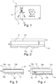
- FIG. 1 We have represented on the figure 1 an example of a secure document 1 in accordance with an example of implementation of the invention, for example a bank note.
- Document 1 comprises a substrate 2, preferably made of paper, formed of one or more fibrous jets, which incorporates a security element 10 according to the invention, in the form of a wire (“thread” in English) in the example considered. .
- the security element 10 comprises a support 11 made of thermoplastic material, which ensures the mechanical resistance of the wire.
- This support 11 is for example made of transparent thermoplastic material such as PET or polyester.
- the thickness e of the support 11 ranges, for example, from 2 to 30 ⁇ m and the width w of the element 10 from 1 to 30 mm, and preferably from 4 to 10 mm.
- the support 11 can also be an adhesive layer in the case of a foil for example.
- the security element 10 may comprise on the front a first security structure 12, which may be of various construction, and for example comprise an openwork metal layer, as in the examples of figures 3 and 4 .
- the element 10 can include, as illustrated on the figures 2 to 4 a second security structure comprising a masking layer 14 externally covered by a pattern layer 15.
- this layer may include one or more solid regions 12a and one or more openings 12b.
- the aperture (s) 12b are visible in light transmitted through a window 3 of the document 1 and then define one or more first patterns M1 as illustrated on the figure 5 for example.
- the patterns M1 are for example alphanumeric patterns, or representations of various subjects such as characters, animals, plants, landscapes or monuments.
- the patterns M1 can be found elsewhere on document 1, for example being printed on the substrate or being for example a watermark.
- metallization and / or demetallization means any process comprising at least one metallization or demetallization step. It is in particular a process of selective metallization or a process of metallization then selective demetallization. Preferably, it is a metallization process then selective demetallization.
- selective metallization or “selective demetallization” means respectively a metallization or a non-total demetallization, that is to say which does not take place over the entire surface of the support and thus makes it possible to form at least one pattern.
- the first pattern is formed by printing a metallized ink, in particular metallic.
- the pattern (s) M1 can also be raster images, giving an impression of relief thanks to a shading effect.
- the openings 12b have sizes and a distribution suitable for creating such images.
- the layer 12 can thus form a recognizable image, the subject of which is for example present elsewhere on the document.
- the layer 12 preferably comprises a metallization, it can also include printed patterns, in positive or negative writing, for example with a metallic, magnetic or electrically conductive ink.
- the layer 12 may include a diffusing ink.
- the metal of layer 12 is for example aluminum, copper, tin, gold, nickel, chromium, silver, one of their alloys or one of their mixtures.
- the layer 12 can allow less than 10% of the white light to pass through the solid regions 12a.
- Layer 12 can be colored, in particular with a dye, for example an azo compound.
- the first safety structure 12 can also be produced differently
- the first security structure 12 is constituted by a lenticular network covered or covering a metallization or an impression having openings, which will be visible in transmitted light.
- the first safety structure 12 is constituted by a multilayer interference structure formed by deposition, in particular by a PVD technique, of thin layers of different refractive indices, this interference structure being covered by or covering a metallization or a print with openwork.
- the first security structure 12 is a reflection hologram, the reflective layer of which is perforated.
- the first security structure may also comprise a layer comprising magnetic platelet particles oriented so as to have an opacity which varies with the angle of observation.
- the figure 7 shows an example of such a structure.
- the layer of oriented particles 12c can be covered by an opaque printing having openings 12b.
- the first structure 12 is a diffraction grating 12a which does not cover the entire front face of the support 11.
- This grating can have a two-layer structure, with an embossed layer and a reflective layer.
- the figure 9 shows a variant in which the first structure 12 comprises a layer of cholesteric liquid crystals 12c and an underlying absorbent layer 12a, dark in color, in particular black, with openings 12b.
- the masking layer 14 may not cover the entire corresponding face 11a of the support 11 and have one or more solid regions and one or more openings. Preferably, however, the masking layer 14 completely covers the face 11a.
- the masking layer 14 is non-opaque.
- the semi-transparency of the masking layer 14 may be due to the non-opaque nature of the material of the layer 14.
- composition of the masking layer 14 can be adjusted as a function of the color (L *, a *, b *) of the substrate 2 of document 1, in particular so as to have substantially the same color.
- the masking layer 14 is diffusing and based on pigment (s) dispersed preferably in a binder.
- the masking layer 14 comprises a mixture of at least two charges, in particular nanometric, with different refractive indices.
- the Applicant considers that the mixture of said at least two nanometric charges of different refractive indices makes it possible to amplify the diffusion phenomenon because the nanometric charge of lower refractive index refracts little by little the incident light which travels then a larger optical path and penetrates more within the layer, while the nanometric charge of higher refractive index increases the number of diffusions within the layer. This results in significant penetration and significant diffusion of light within the layer, thereby allowing the layer to mask the underlying structure in reflection without the layer being opaque, which would impair the visibility of the safety element in transmitted light.
- the masking layer 14 may be in the form of a single masking layer, as illustrated, comprising said aforementioned mixture of at least two nanometric fillers.
- At least one of the nanometric fillers comprises colloidal silica (silicon dioxide), in particular pyrogenic, better consists of colloidal fumed silica.
- a nanometric filler comprising silica is advantageous because it has the advantage of not absorbing UV radiation useful for luminescence, which makes it possible to produce the security element with one or more luminescent layers, in particular fluorescent under UV.
- One of the nanometric fillers of the mixture can be present in a mass quantity of between 20 and 80%, better between 30 and 70%, even better between 40 and 60% relative to the mass of the masking layer 14.
- the colloidal silica preferably has a dimension D50 of between 30 and 1000 nm, better between 30 and 500 nm, even better between 50 and 300 nm.
- the security element may comprise, as a nanometric charge, titanium dioxide in the masking layer 14.
- the amount of titanium dioxide is sufficiently low so as not to excessively absorb the UV radiation and allow the use within the security element of at least one luminescent compound, in particular fluorescent under UV (365 nm), for example applied by printing on the masking layer 14 since it is present in the pattern layer 15 or mixed with a varnish or an adhesive security element.
- the titanium dioxide is preferably anatase in nature, since it then has the advantage of having a lower UV absorption compared to titanium dioxide of rutile nature.
- the anatase titanium dioxide is in particular at least partially transparent to UV, and in particular transparent over at least one range of wavelengths in the UV range.
- the other of the nanometric fillers of the mixture can be present in a mass quantity of between 1 and 40%, better between 2 and 30%, even better between 3 and 15% relative to the mass. of the masking layer 14.
- the colloidal silica / titanium dioxide mass ratio is preferably between 0.5 / 1 and 4/1, more preferably between 2/1 and 3/1.
- the titanium dioxide preferably has a dimension D50 of between 30 and 1000 nm, better between 30 and 500 nm, even better between 50 and 300 nm.
- said at least two nanometric fillers are respectively colloidal silica, preferably pyrogenic, and titanium dioxide, preferably anatase.
- colloidal silica induces greater light scattering in the short wavelengths (blue) and a predominantly red-orange color is therefore obtained in transmission (therefore in specular reflection if the particles are placed on an at least partially reflective layer).
- Titanium dioxide makes it possible to modify the light path by increasing the diffusion within the masking layer 14, which brings greater opacity and thus reduces the red-orange reflective appearance produced by colloidal silica.
- the masking layer 14 further comprises a multilayer interference pigment.
- the multilayer interference pigment has the particularity of preferentially selecting certain wavelengths in reflection and in transmission.
- a blue iridescent pigment reflects in the specular direction (angle of reflection equal to the angle of incidence) more blue wavelengths than others.
- the color obtained is then complementary to the color in reflection, that is to say red-orange.
- Multilayer interference pigments can be relatively transparent, because they are not very absorbent, and consequently a layer of multilayer interference pigment will have, in diffuse reflection (in all other directions other than the specular direction) the same color as in transmission (complementary to the color in specular reflection).
- the layer of blue iridescent pigment spread over white paper will give an orange-red color.
- multilayer interference pigment should be understood to mean a pigment producing a color by an interference phenomenon by virtue of a succession in the path of the light of at least two materials with different refractive indices.
- a pigment Multilayer interference is still sometimes called "mother-of-pearl" in the case of layers deposited on a platelet-shaped base.
- a multilayer interference pigment is different from a liquid crystal, which can also generate color by an interference phenomenon due to its intrinsic structure.
- the combination of the pigment and nanometric charges enhances the scattering of the incident light within the masking layer 14. This combination also makes it possible to limit the proportion of the nanometric charge having the highest refractive index, in particular carbon dioxide. titanium, therefore limiting opacification in transmitted light and, where appropriate, UV absorption.
- the multilayer interference pigment according to the invention comprises a transparent base, preferably mineral, coated with at least one layer of a material with a refractive index different from that of the base.
- the pigment may have a platelet base, preferably made of mica or glass.
- the pigment includes mica or silica (silicon dioxide) coated with titanium dioxide.
- the pigment preferably has a transparent substrate, for example made of mica, and in particular optical characteristics complementary to those of colloidal fumed silica.
- the pigment is preferably blue or green or blue-green.
- the color of the pigment is that obtained by specular reflection of non-normal incidence.
- the interference pigment has a blue, green or blue-green color.
- the average size D50 of the pigment is preferably between 2 and 150 microns, better between 5 and 40 microns, even better between 5 and 25 microns.
- the multilayer interference pigment can be non-goniochromatic, and for example comprise only a single layer coating a base.
- the mass quantity of multilayer interference pigment relative to the mass of the masking layer 14 is preferably between 1 and 40%, better between 2 and 30%, even better between 5 and 15%
- the masking layer 14 is of thin metal.
- the thickness of deposited metal is low enough to maintain a semi-transparency.
- the masking layer 14 is woven metallic and the semi-transparency is obtained by the presence of microscopic openings between the lines of the frame.
- the pattern layer 15 is preferably formed by printing on the masking layer 14.
- the pattern layer 15 is formed using a non-diffusing dye ink.
- a non-diffusing dye ink may be devoid of pigment.
- the advantage of such an ink is its non-diffusing character.
- the pattern layer 15 may or may not comprise a luminescent, in particular fluorescent, compound.
- inks which can be used to form the pattern layer 15 mention may be made of the LEVACELL black PN liquid ink sold by the company Kemira.
- the content of particles (in particular pigments and mineral fillers) of the ink used can be between 0 and 5% by weight, being preferably less than or equal to 2% and more preferably less than 1%.
- the pattern layer 15 can be devoid of luminescent compound, in particular fluorescent at 365 nm or in the infrared.
- the ink is relatively diluted, so as not to absorb visible light too much.
- the amount of dye in the ink can be less than or equal to 5% relative to the weight of the ink.
- the patterns M2 may not be positioned at the mark relative to the patterns M1. In other words, there is not necessarily a predefined relative positioning between a pattern M1 and a pattern M2 along the security element.
- the element 10 may comprise, on the back side, only the masking layer 14 and the pattern layer 15, as illustrated in figures 2 and 3 .
- the masking layer 14 covers a discontinuous magnetic layer 17.
- the solid regions of this magnetic layer 17 are preferably superimposed exclusively on the solid regions 12a of the layer 12, so as not to interfere with the patterns M1 defined by the openings 12b.
- the solid regions of the magnetic layer 17 participate in the definition of the patterns M1 visible in transmitted light.
- the solid regions of the magnetic layer 17 can be covered by a metallic intermediate layer 18, for example aluminum, so as to reduce their visibility on the back side.
- the intermediate layer 18 is itself covered by the masking layer 14.
- the masking layer 14 is continuous and preferably extends over the entire length of the element.
- the masking layer 14 is for example interrupted on certain sections of the element.
- the patterns M2 defined by the pattern layer 15 can be varied and different from the patterns M1.
- the M2 patterns are for example alphanumeric patterns or images of characters, monuments, landscapes, plants or animals.
- the images can be raster images and generate a 3D aspect thanks to a shading effect.
- M2 patterns can be found elsewhere on the document.
- the secure document is not limited to a bank note and can be another means of payment or an identity document or an entry ticket to cultural or sporting events.
- the element 10 may comprise a layer of heat-sealable adhesive on each of its external faces, not shown.
- the effect produced by the safety structure 12 can be observed in reflected light.
- the first security structure 12 is formed by an openwork metal layer, as in the examples of figures 3 and 4 , and when the element 10 is observed in transmission from the side of the front side, being lit from the back side, the patterns M1 are visible in the manner of a CLEARTEXT, as illustrated on the figure 5 .
- the pattern layer 15 does not unduly interfere with the visibility of the patterns M1.
- the security element 10 may be in a form other than a security wire, and for example in the form of a patch or of a structure applied on the surface by transfer, also called "foil" .
- the support 11 can be an adhesive layer, as mentioned above.
- first and second safety structures are located on the same side of the support 11.
- the security element 10 can receive any additional structure increasing security, such as for example a layer of liquid crystals or goniochromatic pigments, a diffraction grating, a hologram, or an optical structure such as a lens. de Fresnel, among other examples.
Landscapes
- Credit Cards Or The Like (AREA)
- Printing Methods (AREA)
- Laminated Bodies (AREA)
Claims (14)
- Sicherheitselement (10) für ein Sicherheitsdokument (3), welches aufweist:- einen wenigstens teilweise lichtdurchlässigen Träger (11),- eine erste Sicherheitsstruktur (12), die von dem Träger getragen wird und wenigstens ein erstes Muster (M1) definiert, das in durchgelassenem Licht sichtbar ist,- eine zweite Sicherheitsstruktur (14, 15), die von dem Träger getragen wird und sich der ersten Struktur (12) wenigstens teilweise überlagert, und die eine semitransparente Maskierungsschicht (14) und eine nicht streuende und semitransparente Musterschicht (15), welche die Maskierungsschicht (14) außen bedeckt und durch Kontrast mit dieser wenigstens ein zweites Muster (M2) definiert, aufweist, dadurch gekennzeichnet, dass das zweite Muster (M2) ausschließlich in Reflexion von der Seite der Musterschicht (15) sichtbar ist, und dadurch, dass:- die Maskierungsschicht (14) lichtstreuend ist und einen Pigmentfüllstoff aufweist, wobei die Maskierungsschicht (14) eine Mischung von wenigstens zwei nanometrischen Füllstoffen mit unterschiedlichen Brechungsindizes aufweist, oder- die Maskierungsschicht (14) metallisch und von geringer Dicke und/oder metallisch und gerastert ist.
- Element (10) nach Anspruch 1, wobei die nicht streuende Musterschicht (15) durch einen Druck mit einer Farbtinte gebildet wird, die insbesondere keinerlei partikelförmige Füllstoffe aufweist.
- Element nach Anspruch 1, wobei die nicht streuende Musterschicht (15) durch eine Abscheidung von Metall gebildet wird.
- Element nach einem der Ansprüche 1 bis 3, welches eine magnetische Schicht (17) aufweist, die wenigstens teilweise von der Maskierungsschicht (14) bedeckt wird, wobei die magnetische Schicht (17) insbesondere unterbrochen ist.
- Element nach Anspruch 4, welches eine metallische Zwischenschicht (18) zwischen der Maskierungsschicht (14) und der magnetischen Schicht (17) aufweist, wobei die metallische Zwischenschicht (18) unterbrochen sein kann, insbesondere wenn die magnetische Schicht unterbrochen ist.
- Element nach einem der vorhergehenden Ansprüche, wobei die erste Struktur (12) von einer Metallschicht gebildet wird, die auf dem Substrat selektiv vorhanden ist, insbesondere mit Durchbrechungen (12b), die das erste Muster (M1) definieren.
- Element nach einem der vorhergehenden Ansprüche, wobei die Maskierungsschicht (14) weiß ist.
- Element nach einem der Ansprüche 1 bis 7, wobei sich die Maskierungsschicht (14) durchgehend erstreckt, wobei die Maskierungsschicht (14) insbesondere mehr als 50 % der Seite (11a) des Trägers (11) bedeckt, welche sie bedeckt, besser mehr als 75 %, noch besser 100 %.
- Element nach einem der Ansprüche 1 bis 8, wobei die Musterschicht (15) weniger als 100 % der Maskierungsschicht (14) bedeckt, besser weniger als 50 %, wobei die Musterschicht (15) insbesondere im Wesentlichen durchlässig für UV-Strahlung von 365 nm ist.
- Element nach einem der vorhergehenden Ansprüche, wobei die erste und die zweite Strukturen auf entgegengesetzten Seiten (11a, 11b) des Trägers angeordnet sind.
- Element nach einem der vorhergehenden Ansprüche, wobei der Träger (11) einen Film aus lichtdurchlässigem thermoplastischem Material, vorzugsweise PET, aufweist, insbesondere daraus besteht.
- Element (10) nach einem der vorhergehenden Ansprüche, das die Form eines Sicherheitsfadens aufweist.
- Sicherheitsdokument (1), welches ein Sicherheitselement (10) nach einem der vorhergehenden Ansprüche aufweist, wobei das Element (10) insbesondere ein Sicherheitsfaden ist, der sich in (einem) Fenster(n) (3) erstreckt.
- Verfahren zur Authentifizierung eines Dokuments (1) nach Anspruch 13, welches die folgenden Schritte umfasst:- Betrachten des Sicherheitselements (10) in durchgelassenem Licht,- Betrachten des Sicherheitselements (10) in reflektiertem Licht, auf der Vorderseite und auf der Rückseite,- Erzeugen wenigstens einer Information, welche die Authentizität des Dokuments (1) betrifft, auf der Basis der durchgeführten Betrachtungen.
Applications Claiming Priority (2)
| Application Number | Priority Date | Filing Date | Title |
|---|---|---|---|
| FR1459788A FR3026988B1 (fr) | 2014-10-13 | 2014-10-13 | Element de securite pour document securise |
| PCT/EP2015/073590 WO2016059005A1 (fr) | 2014-10-13 | 2015-10-12 | Element de securite pour document securise |
Publications (2)
| Publication Number | Publication Date |
|---|---|
| EP3206885A1 EP3206885A1 (de) | 2017-08-23 |
| EP3206885B1 true EP3206885B1 (de) | 2020-06-17 |
Family
ID=52102865
Family Applications (1)
| Application Number | Title | Priority Date | Filing Date |
|---|---|---|---|
| EP15784595.9A Revoked EP3206885B1 (de) | 2014-10-13 | 2015-10-12 | Sicherheitselement für ein sicherheitsdokument |
Country Status (3)
| Country | Link |
|---|---|
| EP (1) | EP3206885B1 (de) |
| FR (1) | FR3026988B1 (de) |
| WO (1) | WO2016059005A1 (de) |
Families Citing this family (2)
| Publication number | Priority date | Publication date | Assignee | Title |
|---|---|---|---|---|
| CN108171866B (zh) * | 2018-01-09 | 2020-07-21 | 深圳怡化电脑股份有限公司 | 纸币图案数据的获取方法、装置、atm及存储介质 |
| IT202300018588A1 (it) * | 2023-09-11 | 2025-03-11 | Linari Eng S R L | Dispositivo di marcatura anticontraffazione e processo di fabbricazione dello stesso |
Citations (7)
| Publication number | Priority date | Publication date | Assignee | Title |
|---|---|---|---|---|
| WO1999004983A1 (de) | 1997-07-24 | 1999-02-04 | Giesecke & Devrient Gmbh | Sicherheitsdokument |
| WO2003053713A1 (de) | 2001-12-21 | 2003-07-03 | Giesecke & Devrient Gmbh | Sicherheitselement für sicherheitspapiere und wertdokumente |
| WO2009053673A1 (en) | 2007-10-23 | 2009-04-30 | De La Rue International Limited | Improvements in security elements |
| WO2009149831A2 (de) | 2008-06-12 | 2009-12-17 | Giesecke & Devrient Gmbh | Sicherheitselement mit optisch variablem element |
| US20100015337A1 (en) | 2006-04-13 | 2010-01-21 | M-Real Oyj | Method for applying interference pigments to a substrate |
| US20120025514A1 (en) | 2009-02-03 | 2012-02-02 | Arjowiggins Security | Security element including two stacked distinct patterns, security document containing same, and related methods |
| WO2013050140A1 (de) | 2011-10-04 | 2013-04-11 | Hueck Folien Ges.M.B.H. | Sicherheitselement mit farbkippeffekt, verfahren zu dessen herstellung und dessen verwendung |
-
2014
- 2014-10-13 FR FR1459788A patent/FR3026988B1/fr not_active Expired - Fee Related
-
2015
- 2015-10-12 WO PCT/EP2015/073590 patent/WO2016059005A1/fr not_active Ceased
- 2015-10-12 EP EP15784595.9A patent/EP3206885B1/de not_active Revoked
Patent Citations (7)
| Publication number | Priority date | Publication date | Assignee | Title |
|---|---|---|---|---|
| WO1999004983A1 (de) | 1997-07-24 | 1999-02-04 | Giesecke & Devrient Gmbh | Sicherheitsdokument |
| WO2003053713A1 (de) | 2001-12-21 | 2003-07-03 | Giesecke & Devrient Gmbh | Sicherheitselement für sicherheitspapiere und wertdokumente |
| US20100015337A1 (en) | 2006-04-13 | 2010-01-21 | M-Real Oyj | Method for applying interference pigments to a substrate |
| WO2009053673A1 (en) | 2007-10-23 | 2009-04-30 | De La Rue International Limited | Improvements in security elements |
| WO2009149831A2 (de) | 2008-06-12 | 2009-12-17 | Giesecke & Devrient Gmbh | Sicherheitselement mit optisch variablem element |
| US20120025514A1 (en) | 2009-02-03 | 2012-02-02 | Arjowiggins Security | Security element including two stacked distinct patterns, security document containing same, and related methods |
| WO2013050140A1 (de) | 2011-10-04 | 2013-04-11 | Hueck Folien Ges.M.B.H. | Sicherheitselement mit farbkippeffekt, verfahren zu dessen herstellung und dessen verwendung |
Also Published As
| Publication number | Publication date |
|---|---|
| FR3026988B1 (fr) | 2021-07-02 |
| WO2016059005A1 (fr) | 2016-04-21 |
| FR3026988A1 (fr) | 2016-04-15 |
| EP3206885A1 (de) | 2017-08-23 |
Similar Documents
| Publication | Publication Date | Title |
|---|---|---|
| EP2984229B1 (de) | Sicherheitselement mit einem interferenzpigment und einem nanometrischen füllstoff | |
| EP3077216B1 (de) | Sicherheitsstruktur | |
| FR2977190A1 (fr) | Amélioration de dispositifs de sécurité incorporant des encres de décalage de couleur | |
| EP2780173A1 (de) | Mehrschichtige struktur | |
| FR2965752A1 (fr) | Structure de securite incorporant des microperforations | |
| EP3194178B1 (de) | Sicherheitselement | |
| EP3083258B1 (de) | Sicherheitselement | |
| EP3206885B1 (de) | Sicherheitselement für ein sicherheitsdokument | |
| EP2864131B1 (de) | Sicherheitselement und dokument damit | |
| EP3384087B1 (de) | Sicherheitselement und sicherheitsdokument | |
| EP2984227B1 (de) | Sicherheitselement mit einer maskierungsstruktur mit einer mischung aus nanometrischen füllstoffen | |
| EP3206884B1 (de) | Sicherheitselement und sicherheitsdokument | |
| EP3023259B1 (de) | Sicherheitselement | |
| CA2947108C (fr) | Bandeau de securite et document de securite qui l'integre |
Legal Events
| Date | Code | Title | Description |
|---|---|---|---|
| STAA | Information on the status of an ep patent application or granted ep patent |
Free format text: STATUS: THE INTERNATIONAL PUBLICATION HAS BEEN MADE |
|
| PUAI | Public reference made under article 153(3) epc to a published international application that has entered the european phase |
Free format text: ORIGINAL CODE: 0009012 |
|
| STAA | Information on the status of an ep patent application or granted ep patent |
Free format text: STATUS: REQUEST FOR EXAMINATION WAS MADE |
|
| 17P | Request for examination filed |
Effective date: 20170331 |
|
| AK | Designated contracting states |
Kind code of ref document: A1 Designated state(s): AL AT BE BG CH CY CZ DE DK EE ES FI FR GB GR HR HU IE IS IT LI LT LU LV MC MK MT NL NO PL PT RO RS SE SI SK SM TR |
|
| AX | Request for extension of the european patent |
Extension state: BA ME |
|
| RAP1 | Party data changed (applicant data changed or rights of an application transferred) |
Owner name: OBERTHUR FIDUCIAIRE SAS |
|
| DAV | Request for validation of the european patent (deleted) | ||
| DAX | Request for extension of the european patent (deleted) | ||
| STAA | Information on the status of an ep patent application or granted ep patent |
Free format text: STATUS: EXAMINATION IS IN PROGRESS |
|
| 17Q | First examination report despatched |
Effective date: 20190123 |
|
| GRAP | Despatch of communication of intention to grant a patent |
Free format text: ORIGINAL CODE: EPIDOSNIGR1 |
|
| STAA | Information on the status of an ep patent application or granted ep patent |
Free format text: STATUS: GRANT OF PATENT IS INTENDED |
|
| INTG | Intention to grant announced |
Effective date: 20200115 |
|
| GRAS | Grant fee paid |
Free format text: ORIGINAL CODE: EPIDOSNIGR3 |
|
| GRAA | (expected) grant |
Free format text: ORIGINAL CODE: 0009210 |
|
| STAA | Information on the status of an ep patent application or granted ep patent |
Free format text: STATUS: THE PATENT HAS BEEN GRANTED |
|
| AK | Designated contracting states |
Kind code of ref document: B1 Designated state(s): AL AT BE BG CH CY CZ DE DK EE ES FI FR GB GR HR HU IE IS IT LI LT LU LV MC MK MT NL NO PL PT RO RS SE SI SK SM TR |
|
| REG | Reference to a national code |
Ref country code: GB Ref legal event code: FG4D Free format text: NOT ENGLISH |
|
| REG | Reference to a national code |
Ref country code: CH Ref legal event code: EP |
|
| REG | Reference to a national code |
Ref country code: IE Ref legal event code: FG4D Free format text: LANGUAGE OF EP DOCUMENT: FRENCH |
|
| REG | Reference to a national code |
Ref country code: DE Ref legal event code: R096 Ref document number: 602015054433 Country of ref document: DE |
|
| REG | Reference to a national code |
Ref country code: AT Ref legal event code: REF Ref document number: 1280858 Country of ref document: AT Kind code of ref document: T Effective date: 20200715 |
|
| PG25 | Lapsed in a contracting state [announced via postgrant information from national office to epo] |
Ref country code: NO Free format text: LAPSE BECAUSE OF FAILURE TO SUBMIT A TRANSLATION OF THE DESCRIPTION OR TO PAY THE FEE WITHIN THE PRESCRIBED TIME-LIMIT Effective date: 20200917 Ref country code: FI Free format text: LAPSE BECAUSE OF FAILURE TO SUBMIT A TRANSLATION OF THE DESCRIPTION OR TO PAY THE FEE WITHIN THE PRESCRIBED TIME-LIMIT Effective date: 20200617 Ref country code: GR Free format text: LAPSE BECAUSE OF FAILURE TO SUBMIT A TRANSLATION OF THE DESCRIPTION OR TO PAY THE FEE WITHIN THE PRESCRIBED TIME-LIMIT Effective date: 20200918 Ref country code: LT Free format text: LAPSE BECAUSE OF FAILURE TO SUBMIT A TRANSLATION OF THE DESCRIPTION OR TO PAY THE FEE WITHIN THE PRESCRIBED TIME-LIMIT Effective date: 20200617 Ref country code: SE Free format text: LAPSE BECAUSE OF FAILURE TO SUBMIT A TRANSLATION OF THE DESCRIPTION OR TO PAY THE FEE WITHIN THE PRESCRIBED TIME-LIMIT Effective date: 20200617 |
|
| REG | Reference to a national code |
Ref country code: LT Ref legal event code: MG4D |
|
| REG | Reference to a national code |
Ref country code: NL Ref legal event code: MP Effective date: 20200617 |
|
| PG25 | Lapsed in a contracting state [announced via postgrant information from national office to epo] |
Ref country code: RS Free format text: LAPSE BECAUSE OF FAILURE TO SUBMIT A TRANSLATION OF THE DESCRIPTION OR TO PAY THE FEE WITHIN THE PRESCRIBED TIME-LIMIT Effective date: 20200617 Ref country code: LV Free format text: LAPSE BECAUSE OF FAILURE TO SUBMIT A TRANSLATION OF THE DESCRIPTION OR TO PAY THE FEE WITHIN THE PRESCRIBED TIME-LIMIT Effective date: 20200617 Ref country code: HR Free format text: LAPSE BECAUSE OF FAILURE TO SUBMIT A TRANSLATION OF THE DESCRIPTION OR TO PAY THE FEE WITHIN THE PRESCRIBED TIME-LIMIT Effective date: 20200617 |
|
| PG25 | Lapsed in a contracting state [announced via postgrant information from national office to epo] |
Ref country code: AL Free format text: LAPSE BECAUSE OF FAILURE TO SUBMIT A TRANSLATION OF THE DESCRIPTION OR TO PAY THE FEE WITHIN THE PRESCRIBED TIME-LIMIT Effective date: 20200617 Ref country code: NL Free format text: LAPSE BECAUSE OF FAILURE TO SUBMIT A TRANSLATION OF THE DESCRIPTION OR TO PAY THE FEE WITHIN THE PRESCRIBED TIME-LIMIT Effective date: 20200617 |
|
| PG25 | Lapsed in a contracting state [announced via postgrant information from national office to epo] |
Ref country code: ES Free format text: LAPSE BECAUSE OF FAILURE TO SUBMIT A TRANSLATION OF THE DESCRIPTION OR TO PAY THE FEE WITHIN THE PRESCRIBED TIME-LIMIT Effective date: 20200617 Ref country code: PT Free format text: LAPSE BECAUSE OF FAILURE TO SUBMIT A TRANSLATION OF THE DESCRIPTION OR TO PAY THE FEE WITHIN THE PRESCRIBED TIME-LIMIT Effective date: 20201019 Ref country code: CZ Free format text: LAPSE BECAUSE OF FAILURE TO SUBMIT A TRANSLATION OF THE DESCRIPTION OR TO PAY THE FEE WITHIN THE PRESCRIBED TIME-LIMIT Effective date: 20200617 Ref country code: EE Free format text: LAPSE BECAUSE OF FAILURE TO SUBMIT A TRANSLATION OF THE DESCRIPTION OR TO PAY THE FEE WITHIN THE PRESCRIBED TIME-LIMIT Effective date: 20200617 Ref country code: RO Free format text: LAPSE BECAUSE OF FAILURE TO SUBMIT A TRANSLATION OF THE DESCRIPTION OR TO PAY THE FEE WITHIN THE PRESCRIBED TIME-LIMIT Effective date: 20200617 Ref country code: SM Free format text: LAPSE BECAUSE OF FAILURE TO SUBMIT A TRANSLATION OF THE DESCRIPTION OR TO PAY THE FEE WITHIN THE PRESCRIBED TIME-LIMIT Effective date: 20200617 |
|
| PG25 | Lapsed in a contracting state [announced via postgrant information from national office to epo] |
Ref country code: SK Free format text: LAPSE BECAUSE OF FAILURE TO SUBMIT A TRANSLATION OF THE DESCRIPTION OR TO PAY THE FEE WITHIN THE PRESCRIBED TIME-LIMIT Effective date: 20200617 Ref country code: PL Free format text: LAPSE BECAUSE OF FAILURE TO SUBMIT A TRANSLATION OF THE DESCRIPTION OR TO PAY THE FEE WITHIN THE PRESCRIBED TIME-LIMIT Effective date: 20200617 Ref country code: IS Free format text: LAPSE BECAUSE OF FAILURE TO SUBMIT A TRANSLATION OF THE DESCRIPTION OR TO PAY THE FEE WITHIN THE PRESCRIBED TIME-LIMIT Effective date: 20201017 |
|
| REG | Reference to a national code |
Ref country code: AT Ref legal event code: UEP Ref document number: 1280858 Country of ref document: AT Kind code of ref document: T Effective date: 20200617 |
|
| REG | Reference to a national code |
Ref country code: DE Ref legal event code: R026 Ref document number: 602015054433 Country of ref document: DE |
|
| PLBI | Opposition filed |
Free format text: ORIGINAL CODE: 0009260 |
|
| PLAX | Notice of opposition and request to file observation + time limit sent |
Free format text: ORIGINAL CODE: EPIDOSNOBS2 |
|
| PLAF | Information modified related to communication of a notice of opposition and request to file observations + time limit |
Free format text: ORIGINAL CODE: EPIDOSCOBS2 |
|
| 26 | Opposition filed |
Opponent name: GIESECKE+DEVRIENT CURRENCY TECHNOLOGY GMBH Effective date: 20210317 |
|
| PG25 | Lapsed in a contracting state [announced via postgrant information from national office to epo] |
Ref country code: DK Free format text: LAPSE BECAUSE OF FAILURE TO SUBMIT A TRANSLATION OF THE DESCRIPTION OR TO PAY THE FEE WITHIN THE PRESCRIBED TIME-LIMIT Effective date: 20200617 |
|
| PG25 | Lapsed in a contracting state [announced via postgrant information from national office to epo] |
Ref country code: SI Free format text: LAPSE BECAUSE OF FAILURE TO SUBMIT A TRANSLATION OF THE DESCRIPTION OR TO PAY THE FEE WITHIN THE PRESCRIBED TIME-LIMIT Effective date: 20200617 |
|
| PG25 | Lapsed in a contracting state [announced via postgrant information from national office to epo] |
Ref country code: LU Free format text: LAPSE BECAUSE OF NON-PAYMENT OF DUE FEES Effective date: 20201012 Ref country code: MC Free format text: LAPSE BECAUSE OF FAILURE TO SUBMIT A TRANSLATION OF THE DESCRIPTION OR TO PAY THE FEE WITHIN THE PRESCRIBED TIME-LIMIT Effective date: 20200617 |
|
| REG | Reference to a national code |
Ref country code: BE Ref legal event code: MM Effective date: 20201031 |
|
| PLBB | Reply of patent proprietor to notice(s) of opposition received |
Free format text: ORIGINAL CODE: EPIDOSNOBS3 |
|
| PG25 | Lapsed in a contracting state [announced via postgrant information from national office to epo] |
Ref country code: BE Free format text: LAPSE BECAUSE OF NON-PAYMENT OF DUE FEES Effective date: 20201031 |
|
| PG25 | Lapsed in a contracting state [announced via postgrant information from national office to epo] |
Ref country code: IE Free format text: LAPSE BECAUSE OF NON-PAYMENT OF DUE FEES Effective date: 20201012 |
|
| PG25 | Lapsed in a contracting state [announced via postgrant information from national office to epo] |
Ref country code: TR Free format text: LAPSE BECAUSE OF FAILURE TO SUBMIT A TRANSLATION OF THE DESCRIPTION OR TO PAY THE FEE WITHIN THE PRESCRIBED TIME-LIMIT Effective date: 20200617 Ref country code: MT Free format text: LAPSE BECAUSE OF FAILURE TO SUBMIT A TRANSLATION OF THE DESCRIPTION OR TO PAY THE FEE WITHIN THE PRESCRIBED TIME-LIMIT Effective date: 20200617 Ref country code: CY Free format text: LAPSE BECAUSE OF FAILURE TO SUBMIT A TRANSLATION OF THE DESCRIPTION OR TO PAY THE FEE WITHIN THE PRESCRIBED TIME-LIMIT Effective date: 20200617 |
|
| PG25 | Lapsed in a contracting state [announced via postgrant information from national office to epo] |
Ref country code: MK Free format text: LAPSE BECAUSE OF FAILURE TO SUBMIT A TRANSLATION OF THE DESCRIPTION OR TO PAY THE FEE WITHIN THE PRESCRIBED TIME-LIMIT Effective date: 20200617 |
|
| PGFP | Annual fee paid to national office [announced via postgrant information from national office to epo] |
Ref country code: FR Payment date: 20221031 Year of fee payment: 8 |
|
| PGFP | Annual fee paid to national office [announced via postgrant information from national office to epo] |
Ref country code: IT Payment date: 20221026 Year of fee payment: 8 Ref country code: GB Payment date: 20221020 Year of fee payment: 8 Ref country code: DE Payment date: 20220620 Year of fee payment: 8 Ref country code: BG Payment date: 20221020 Year of fee payment: 8 Ref country code: AT Payment date: 20221020 Year of fee payment: 8 |
|
| PGFP | Annual fee paid to national office [announced via postgrant information from national office to epo] |
Ref country code: CH Payment date: 20221026 Year of fee payment: 8 |
|
| APBM | Appeal reference recorded |
Free format text: ORIGINAL CODE: EPIDOSNREFNO |
|
| APBP | Date of receipt of notice of appeal recorded |
Free format text: ORIGINAL CODE: EPIDOSNNOA2O |
|
| APAH | Appeal reference modified |
Free format text: ORIGINAL CODE: EPIDOSCREFNO |
|
| PLAB | Opposition data, opponent's data or that of the opponent's representative modified |
Free format text: ORIGINAL CODE: 0009299OPPO |
|
| APBQ | Date of receipt of statement of grounds of appeal recorded |
Free format text: ORIGINAL CODE: EPIDOSNNOA3O |
|
| R26 | Opposition filed (corrected) |
Opponent name: GIESECKE+DEVRIENT CURRENCY TECHNOLOGY GMBH Effective date: 20210317 |
|
| REG | Reference to a national code |
Ref country code: DE Ref legal event code: R119 Ref document number: 602015054433 Country of ref document: DE |
|
| REG | Reference to a national code |
Ref country code: CH Ref legal event code: PL |
|
| REG | Reference to a national code |
Ref country code: AT Ref legal event code: MM01 Ref document number: 1280858 Country of ref document: AT Kind code of ref document: T Effective date: 20231012 |
|
| REG | Reference to a national code |
Ref country code: DE Ref legal event code: R103 Ref document number: 602015054433 Country of ref document: DE Ref country code: DE Ref legal event code: R064 Ref document number: 602015054433 Country of ref document: DE |
|
| GBPC | Gb: european patent ceased through non-payment of renewal fee |
Effective date: 20231012 |
|
| APBU | Appeal procedure closed |
Free format text: ORIGINAL CODE: EPIDOSNNOA9O |
|
| APAN | Information on closure of appeal procedure modified |
Free format text: ORIGINAL CODE: EPIDOSCNOA9O |
|
| PG25 | Lapsed in a contracting state [announced via postgrant information from national office to epo] |
Ref country code: GB Free format text: LAPSE BECAUSE OF NON-PAYMENT OF DUE FEES Effective date: 20231012 |
|
| RDAF | Communication despatched that patent is revoked |
Free format text: ORIGINAL CODE: EPIDOSNREV1 |
|
| STAA | Information on the status of an ep patent application or granted ep patent |
Free format text: STATUS: PATENT REVOKED |
|
| PG25 | Lapsed in a contracting state [announced via postgrant information from national office to epo] |
Ref country code: CH Free format text: LAPSE BECAUSE OF NON-PAYMENT OF DUE FEES Effective date: 20231031 |
|
| RDAG | Patent revoked |
Free format text: ORIGINAL CODE: 0009271 |
|
| PG25 | Lapsed in a contracting state [announced via postgrant information from national office to epo] |
Ref country code: AT Free format text: LAPSE BECAUSE OF NON-PAYMENT OF DUE FEES Effective date: 20231012 |
|
| PG25 | Lapsed in a contracting state [announced via postgrant information from national office to epo] |
Ref country code: GB Free format text: LAPSE BECAUSE OF NON-PAYMENT OF DUE FEES Effective date: 20231012 Ref country code: FR Free format text: LAPSE BECAUSE OF NON-PAYMENT OF DUE FEES Effective date: 20231031 Ref country code: DE Free format text: LAPSE BECAUSE OF NON-PAYMENT OF DUE FEES Effective date: 20240501 Ref country code: CH Free format text: LAPSE BECAUSE OF NON-PAYMENT OF DUE FEES Effective date: 20231031 Ref country code: BG Free format text: LAPSE BECAUSE OF NON-PAYMENT OF DUE FEES Effective date: 20231012 Ref country code: AT Free format text: LAPSE BECAUSE OF NON-PAYMENT OF DUE FEES Effective date: 20231012 |
|
| REG | Reference to a national code |
Ref country code: CH Ref legal event code: PL |
|
| 27W | Patent revoked |
Effective date: 20240625 |
|
| REG | Reference to a national code |
Ref country code: AT Ref legal event code: MA03 Ref document number: 1280858 Country of ref document: AT Kind code of ref document: T Effective date: 20240625 |
|
| PG25 | Lapsed in a contracting state [announced via postgrant information from national office to epo] |
Ref country code: IT Free format text: LAPSE BECAUSE OF NON-PAYMENT OF DUE FEES Effective date: 20231012 |