EP3206907B1 - Support à utiliser dans un appui-tête coulissant - Google Patents
Support à utiliser dans un appui-tête coulissant Download PDFInfo
- Publication number
- EP3206907B1 EP3206907B1 EP14903940.6A EP14903940A EP3206907B1 EP 3206907 B1 EP3206907 B1 EP 3206907B1 EP 14903940 A EP14903940 A EP 14903940A EP 3206907 B1 EP3206907 B1 EP 3206907B1
- Authority
- EP
- European Patent Office
- Prior art keywords
- less
- generally cylindrical
- cylindrical sidewall
- head restraint
- posts
- Prior art date
- Legal status (The legal status is an assumption and is not a legal conclusion. Google has not performed a legal analysis and makes no representation as to the accuracy of the status listed.)
- Active
Links
Images













Classifications
-
- B—PERFORMING OPERATIONS; TRANSPORTING
- B60—VEHICLES IN GENERAL
- B60N—SEATS SPECIALLY ADAPTED FOR VEHICLES; VEHICLE PASSENGER ACCOMMODATION NOT OTHERWISE PROVIDED FOR
- B60N2/00—Seats specially adapted for vehicles; Arrangement or mounting of seats in vehicles
- B60N2/80—Head-rests
- B60N2/806—Head-rests movable or adjustable
- B60N2/809—Head-rests movable or adjustable vertically slidable
- B60N2/812—Head-rests movable or adjustable vertically slidable characterised by their locking devices
- B60N2/815—Release mechanisms, e.g. buttons
-
- F—MECHANICAL ENGINEERING; LIGHTING; HEATING; WEAPONS; BLASTING
- F16—ENGINEERING ELEMENTS AND UNITS; GENERAL MEASURES FOR PRODUCING AND MAINTAINING EFFECTIVE FUNCTIONING OF MACHINES OR INSTALLATIONS; THERMAL INSULATION IN GENERAL
- F16C—SHAFTS; FLEXIBLE SHAFTS; ELEMENTS OR CRANKSHAFT MECHANISMS; ROTARY BODIES OTHER THAN GEARING ELEMENTS; BEARINGS
- F16C29/00—Bearings for parts moving only linearly
- F16C29/02—Sliding-contact bearings
-
- B—PERFORMING OPERATIONS; TRANSPORTING
- B60—VEHICLES IN GENERAL
- B60N—SEATS SPECIALLY ADAPTED FOR VEHICLES; VEHICLE PASSENGER ACCOMMODATION NOT OTHERWISE PROVIDED FOR
- B60N2/00—Seats specially adapted for vehicles; Arrangement or mounting of seats in vehicles
- B60N2/80—Head-rests
- B60N2/897—Head-rests with sleeves located in the back-rest for guiding the rods of the head-rest
-
- F—MECHANICAL ENGINEERING; LIGHTING; HEATING; WEAPONS; BLASTING
- F16—ENGINEERING ELEMENTS AND UNITS; GENERAL MEASURES FOR PRODUCING AND MAINTAINING EFFECTIVE FUNCTIONING OF MACHINES OR INSTALLATIONS; THERMAL INSULATION IN GENERAL
- F16C—SHAFTS; FLEXIBLE SHAFTS; ELEMENTS OR CRANKSHAFT MECHANISMS; ROTARY BODIES OTHER THAN GEARING ELEMENTS; BEARINGS
- F16C29/00—Bearings for parts moving only linearly
- F16C29/12—Arrangements for adjusting play
- F16C29/123—Arrangements for adjusting play using elastic means
Definitions
- Automotive vehicles include vehicle seat assemblies for supporting vehicle occupants.
- the seat assemblies typically include a substantially horizontal seat cushion and a generally upright seat back pivotally connected to the seat cushion by a rotatable mechanism.
- Seat assemblies also typically include a head restraint extending from a top face of the seat back. The head restraint is typically movable between a plurality of head restraint positions relative to the seat back to accommodate a wide range of occupant heights.
- Each of the posts can extend outward from the head restraint and can be inserted into a corresponding mounting fixture in the seat back.
- Either one or both of the posts typically contain a plurality of external notches arranged longitudinally thereon, representing the corresponding plurality of head restraint selectable positions.
- a plunger or depressor can be engaged with any one of the plurality of notches to maintain the head restraint in the corresponding head support position.
- the plunger is typically spring biased such that in the biased position, the plunger engages with one of the notches, thus preventing axial translation of the head restraint relative the seat back.
- a vehicle occupant can depress the plunger, causing the plunger to disengage from a notch on the post. After the plunger disengages from the notch, the occupant can apply a force to the head restraint, causing the entire head restraint assembly to translate in the desired vertical direction. For example, to lower the height of the head restraint, the occupant can urge the assembly towards the seat back. Conversely, to increase the height of the head restraint, the occupant can urge the assembly away from the seat back.
- the occupant can release the plunger, allowing the plunger to once again bias against the post. If at this time the plunger is aligned with one of the notches, the plunger can engage therewith, causing the head restraint to securely lock in that position. However, if the plunger is not aligned with a notch, the occupant must then urge the head restraint in either vertical direction until the plunger engages with the nearest notch, at which point the head restraint is securely locked.
- Previous adjustable head restraint assemblies have relied on intentional misalignment of the posts relative to the engagement fixture in the seat back. This misalignment can allow the posts to form an interference fit with the mounting fixture of the seat back. This misalignment has several undesirable consequences. Particularly, the misalignment can cause the assembly to exhibit a high seat assembly to seat assembly variability, such as in terms of ease of headrest adjustment and/or tolerances. Moreover, the misalignment can cause undesirable noise, vibration, and harshness characteristics.
- EP 1 690 732 A2 is concerned with a headrest support which can support a headrest which is mounted on the transport means by way of a receiving member and/or a headrest stay by completely eliminating a play of the headrest (setting the play to approximately zero) and a locking member which is assembled to the headrest support.
- a further head restraint guide sleeve is known from KR 2013 0089125 A .
- the term “adjustment length” describes the maximum distance the posts can translate into and away from a seat back while maintaining lockable engagement therewith.
- the “adjustment length” can be defined as the length of the segment of the head restraint post that is exposed from the seat back when the head restraint assembly is at its maximum height.
- the “adjustment length” of the posts can be less than the entire axial length of the posts. Further, as described herein, the posts can be locked at any position along their adjustment length.
- the present head restraint assembly is adapted to provide consistent sliding resistance and adjustability.
- the concepts are better understood in view of the embodiments described below that illustrate and do not limit the scope of the present invention.
- the seat 2 can include a seat bottom (not shown) that is mounted within a vehicle.
- the seat 2 can also include a seat back 4 that is mounted to one of the seat bottom or the vehicle.
- the seat back 4 can further include a head restraint assembly 1.
- the head restraint assembly 1 can be engaged with a top surface 6 of the seat back 4.
- the head restraint assembly 1 can be adapted to translate relative to the seat back 4. In this regard, the head restraint assembly 1 can be adjusted to accommodate passengers of various heights.
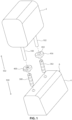
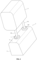
- the head restraint assembly 1 can generally include a body (e.g., a head cushion) 2, a first post 100 and a second post 102 extending from the head cushion 2, a first guide sleeve 200 engaged with the first post 100, and a second guide sleeve 202 engaged with the second post 102.
- the first guide sleeve 200 can further include a first bearing 300 having a first and second distal end, and a locking mechanism 400.
- the second guide sleeve 202 can further include a second bearing 300 having a first and second distal end.
- the first and second bearings 300, 302 can each have a first end 306 and a second end 308, the second end 308 having substantially the same shape as the first end 306.
- the locking mechanism 400 can be engaged to the first end 306.
- the head cushion 2 can be made of a foamed polymer material and can have an internal framework.
- the head cushion 2 can further include an outer material selected to cover the foamed plastic, such as, for example, a vinyl, a fabric, a leather, or a combination thereof.
- the internal framework can comprise any rigid material sufficient to support the head cushion 8.
- the internal framework can be formed from several axial members affixed together or from a single piece. Extending from the internal framework can be the first and second posts 100 and 102.
- the posts 100, 102 can be integral with the framework or can be attached to the framework in any manner recognizable to one having ordinary skill in the art. For example, the posts 100, 102 can be welded to the framework.
- the posts 100, 102 can be mechanically deformed to engage the framework (e.g., the posts 100, 102 being crimped or bent around the framework).
- the posts 100, 102 can be affixed to the framework by a threadable engagement, or other similar type fastener.
- first and second posts 100, 102 can extend in a substantially parallel orientation from the head cushion 2. In a further embodiment, the first and second posts 100, 102 can extend from the head cushion 2 in a parallel fashion.
- substantially parallel refers to a relative angle as formed between two lines or planes of no greater than 10°, such as no greater than 5°, or even no greater than 1°.
- parallel refers to a relative angle as formed between two lines or planes of no greater than 0.1°.
- the posts 100, 102 can be formed of straight, cylindrical rods.
- the posts 100, 102 can have one or more radial bends 104 therein.
- the radial bends 104 can offset the head cushion 2 from the seat back 4.
- the posts 100, 102 can each include an articulated joint to enable rotational adjustment of the head cushion 2 relative to the seat back 4.
- the head cushion 2 can be rotatably articulated around the top of the posts 100, 102.
- the articulated joint can be located within the head cushion 2.
- At least one of the posts 100, 102 can have a stop feature 108 ( FIG. 4 ).
- the stop feature 108 can be adapted to engage with a complementary locking mechanism (described below) affixed to the seat back 4.
- the stop feature 108 can be a radial groove or channel extending at least partially around the circumference, C P .
- the adjustment length, L A can be increased by correspondingly increasing the length of L P .
- L A can be increased by repositioning the stop feature 108 closer to the leading end 106 of the posts 100, 102.
- a ratio of L P :L A can be no greater than 4.0, such as no greater than 3.5, no greater than 3.0, no greater than 2.5, no greater than 2.0, no greater than 1.5 no greater than 1.25, or even no greater than 1.1.
- the ratio of L P :L A can be greater than 1.0, such as greater than 1.1, greater than 1.2, greater than 1.3, greater than 1.4, greater than 1.5, greater than 1.6, greater than 1.7, greater than 1.8, greater than 1.9, or even greater than 2.0.
- the value for the ratio of L P :L A can be selected from a value as within the range defined above.
- the stop feature 108 can be separated from the leading end 106 of the posts 100, 102 a length, L SF , as measured between the leading end 106 and the nearest surface of the stop feature 108.
- a ratio of L P :L SF can be no greater than 100, such as no greater than 75, no greater than 50, no greater than 25, or even no greater than 10.
- the ratio of L P :L SF can be no less than 0.5, such as no less than 1, no less than 5, no less than 10, no less than 20, no less than 30, no less than 40, or even no less than 50.
- the value for the ratio of L P :L SF can be selected from a value as within the range defined above.
- the guide sleeves 200, 202 can additionally include a stop feature 204, which is adapted to engage with the stop feature 108 of the posts 100, 102.
- the stop features 108, 204 can be adapted to prevent the posts 100, 102 from disengaging from the guide sleeve guides 200, 202.
- the stop features 108, 204 can comprise any feature as would be recognizable to one having ordinary skill in the art for preventing axial disengagement of two substantially concentric components.
- one of the stop features 108, 204 can comprise a radial projection 206 adapted to engage with a corresponding recess 208 in the other stop feature 108, 204.
- the radial projection 206 can be spring biased towards the corresponding recess 208.
- the radial projection 206 can engage with the corresponding recess 208 and can prevent the posts 100, 102 from disengaging from the guide sleeves 200, 202.
- the stop features 108, 204 can comprise a molly adapted to be engageable onto one of the posts 100, 102.
- the molly can be spring biased such that after insertion of the posts 100, 102 through the guide sleeves 200, 202, the molly expands or extends radially outward beyond the guide sleeves 200, 202. This expansion or extension can anchor the stop features 108, 204 and prevent the posts 100, 102 from disengaging from the guide sleeves 200, 202.
- the first and second bearings 300, 302 can be adapted to engage around each of the first and second posts 100, 102.
- the posts 100, 102 and the bearings 300, 302 can have a poka yoke or other mechanism to assist in aligning the posts 100, 102 within the bearings 300, 302.
- poka yoke refers to a complementary shaping feature located on each of the posts 100, 102 and the bearings 300, 302 to assist in preventing unintended movement between the parts and to facilitate easier assembly.
- the poka yoke may comprise a tongue and groove extending along an axial length of the posts 100, 102 and the bearings 300, 302.
- the bearings 300, 302 can be formed from a strip 304 of resilient material, e.g. spring steel, having opposite axial ends 306, 308 and circumferential ends 310, 312.
- the strip 304 can include an undeformed portion 316 and at least one row of wave structures 318.
- the wave structures 318 can be press-formed, e.g. stamped, into the strip 304.
- "undeformed portion” can refer to an annular sidewall of the bearing(s) from which wave structure(s) protrude.
- the "undeformed portion” can include a portion of the strip 304 that is not deformed other than during forming of an annular, or cylindrical, shape, e.g., the undeformed portion is devoid of wave structure(s).
- the "undeformed portion” can include an annular sidewall of the bearing(s) defining at least one of an inner diameter or an outer diameter of the bearing(s).
- each wave structure 318 can be substantially identical in size and shape to permit a more even radial compression around the circumference of the bearings 300, 302.
- the wave structures 318 can have a length, L WS , extending at least partially between the axial ends 306, 308.
- the wave structures 318 can extend parallel with the axial ends 306, 308.
- the wave structures 318 can extend in any angular orientation relative the axial ends 306, 308.
- the wave structures 318 can have a uniform projecting distance, D WP . In an alternative embodiment, the wave structures 318 can have varying projecting distances, D WP .
- N WS there can be a number of wave structures, N WS , located peripherally around the bearings 300, 302.
- N WS can be at least 3, such as N WS is at least 4, at least 5, at least 6, at least 7, at least 8, at least 9, at least 10, at least 11, at least 12, at least 13, at least 14, at least 15, or even at least 16.
- N WS can be no greater than 40, such as no greater than 35, not greater than 30, no greater than 25, no greater than 20, no greater than 15, or even not greater than 10.
- N WS can also be within a range between and including any of the above described values.
- the bearings 300, 302 can be adapted to receive an angled post 100, 102 therein.
- the wave structures 318 can have variable projecting distances, D WP , to accommodate for this angular engagement.
- the bearings 300, 302 can be adapted to receive off-centered posts 100, 102 that are not concentrically aligned with the bearings 300,302.
- the wave structures 318 can be formed such that the wave structures 318 are substantially identical in the axial direction but increase or decrease circumferentially.
- the ratio of D P :ID F can be no less than 1.005, such as no less than 1.01, no less than 1.02, no less than 1.03, no less than 1.04, no less than 1.05, no less than 1.06, no less than 1.07, no less than 1.08, no less than 1.09, or even no less than 1.1. Additionally, the ratio of D P :ID F can also be within a range between and including any of the ratio values described above. In a particular aspect, as the ratio of D P :ID F increases, the wave structures 318 can provide a greater radial force against the posts 100, 102.
- the bearings 300, 302 can further comprise a total circumference, C T , which can be measured by a best fit circle along the inner surface 336 of the undeformed portion 316 of the bearings 300, 302 prior to insertion of the posts 100, 102 therein.
- the ratio of W GI :C T can be no less than 0.01, such as no less than 0.02, no less than 0.03, no less than 0.04, no less than 0.05, no less than 0.06, no less than 0.07, no less than 0.08, no less than 0.09, or even no less than 0.10.
- the ratio of W GI :C T can also be within a range between and including any of the ratio values described above.
- C T can be understood to include both the circumferential length of the inner surface 336 of the bearing 300, 302 and the length, W GI , of the gap 314.
- the bearings 300, 302 can have an operational inner diameter, ID O , which can be measured between the inner surface 320 of two opposite wave structures 318, 318 after engagement of the bearings 300, 302 with the posts 100, 102.
- ID O an operational inner diameter
- a ratio of ID O :ID F can be no less than 1.05, such as no less than 1.10, no less than 1.15, no less than 1.20, no less than 1.25, no less than 1.30, no less than 1.35, no less than 1.40, no less than 1.45, no less than 1.50, no less than 1.55, or even no less than 1.60.
- the bearings 300, 302 can have a functional circumference, as measured by a best fit circle along the undeformed portion 316 of the bearings 300, 302 after insertion of the posts 100, 102 therein.
- a ratio of C T :C F can be at least 1.025, at least 1.05, at least 1.1, at least 1.2, at least 1.3, at least 1.4, at least 1.5, at least 1.75, or even at least 2.0.
- the ratio of C T :C F can be less than 5, less than 4, less than 3, less than 2, or even less than 1.5.
- the ratio of C T :C F can also be within a range between and including any of the ratio values described above.
- the material includes polyketone, such as polyether ether ketone (PEEK), polyether ketone, polyether ketone ketone, polyether ketone ether ketone, a derivative thereof, or a combination thereof.
- the thermoplastic polymer may be ultra high molecular weight polyethylene.
- An example fluoropolymer includes fluorinated ethylene propylene (FEP), PTFE, polyvinylidene fluoride (PVDF), perfluoroalkoxy (PFA), a terpolymer of tetrafluoroethylene, hexafluoropropylene, and vinylidene fluoride (THV), polychlorotrifluoroethylene (PCTFE), ethylene tetrafluoroethylene copolymer (ETFE), ethylene chlorotrifluoroethylene copolymer (ECTFE), or any combination thereof. Fluoropolymers are used according to particular embodiments.
- the bearings 300, 302 can include lubrication to further enhance sliding characteristics between the bearing 300, 202 and the posts 100, 102.
- Exemplary lubricants can include molybdenum disulfide, tungsten disulfide, graphite, grapheme, expanded graphite, boron nitrade, talc, calcium fluoride, or any combination thereof.
- the lubricant can comprise alumina, silica, titanium dioxide, calcium fluoride, boron nitride, mica, Wollastonite, silicon carbide, silicon nitride, zirconia, carbon black, pigments, or any combination thereof.
- a combination of the spring characteristics of the bearing 300, 302 with the low friction/lubrication characteristics of the low friction layer 324 can provide a low friction sliding surface.
- the strip 304 can have a thickness, T S
- the low friction layer 324 can have a thickness, T LFL .
- a ratio of T S :T LFL can be at least 1, such as at least 1.5, at least 2, at least 2.5, at least 3, at least 3.5, at least 4, at least 4.5, or even at least 5.
- the ratio of T S :T LFL can be no greater than 50, such as no greater than 40, no greater than 30, no greater than 20, or even no greater than 10. Additionally, the ratio of T S :T LFL can be within a range between and including any of the ratio values described above.
- the low friction layer 324 can have a thickness of no less than 0.01 mm, such as no less than 0.05 mm, no less than 0.1 mm, no less than 0.2 mm, no less than 0.3 mm, no less than 0.4 mm, no less than 0.5 mm, no less than 0.6 mm, no less than 0.7 mm, no less than 0.8 mm, no less than 0.9 mm, or even no less than 1 mm.
- the thickness of the low friction layer 324 can be no greater than 10 mm, such as no greater than 9 mm, no greater than 8 mm, no greater than 7 mm, no greater than 6 mm, no greater than 5 mm, no greater than 4 mm, no greater than 3 mm, no greater than 2 mm, or even no greater than 1 mm. Additionally, the thickness of the low friction layer 324 can also be within a range between and including any of the ratio values described above.
- the bearings 300, 302 can reduce frictional resistance of the posts 100, 102 within the guide sleeves 200, 202, allowing for easier translation of the head restraint assembly 1 relative the seat back 4.
- the bearings 300, 302 can provide a zero-clearance fit between the guide sleeves 200, 202 and the posts 100, 102.
- the bearings 300, 302 can eliminate or substantially reduce squeaking of the assembly 1 when the posts 100, 102 are translated relative the guide sleeves 200, 202.
- the bearings 300, 302 can be adapted to apply a radially inward force against the posts 100, 102 so as to form a "zero-clearance" fit therebetween.
- a zero-clearance fit can be formed between the bearings 300, 302 and the posts 100, 102.
- zero-clearance is defined by an engagement between a bearing and a post substantially devoid of perceptible radial play or movement upon application of a force against the bearing perpendicular to the central axis of the bearing, while holding the post installed therein stationary at 0 degrees, 45 degrees, 90 degrees, 135 degrees, 180 degrees, 225 degrees, and 270 degrees positions.
- the bearings 300, 302 it is desirable for the bearings 300, 302 to provide a high degree of radial stiffness to the posts 100, 102 while simultaneously permitting low axial sliding forces of the posts 100, 102 within the bearings 300, 302.
- the head restraint assembly 1 can support high normal loads while simultaneously permitting translation of the posts 100, 102 within the bearings 300, 302 upon application of a minimal axial load.
- Radial stiffness of the bearings 300, 302 can be determined at anytime after insertion of the posts 100, 102 in the bearings 300, 302. For example, after one of the posts 100, 102 has been inserted into one of the bearings 300, 302 as previously described, the radial stiffness of the post 100, 102 and bearing 300, 302 preassembly can be determined by fixing one of the post 100, 102 or bearings 300, 302 and applying a perpendicular normal force to the other one of the post 100, 102 or bearings 300, 302. The force necessary to affect radial movement of one of the posts 100, 102 or bearings 300, 302 can be determinative of the radial stiffness of the bearings 300, 302.
- each of the wave structures 318 can have a best fit circle having an initial diameter, D I , as measured by the diameter of the best fit circle prior to installation of the posts 100, 102, and an operational diameter, D O , as measured by the diameter of the best fit circle after installation of the posts 100, 102 therein.
- D I initial diameter
- D O operational diameter
- a zero clearance fit between the bearings 300, 302 and the posts 100, 102 can require that D O be greater than D I .
- a ratio of D I :D O can be no greater than 0.999, no greater than 0.995, no greater than 0.990, no greater than 0.985, no greater than 0.980, no greater than 0.975, no greater than 0.970, no greater than 0.950, no greater than 0.925, no greater than 0.900.
- the ratio of D I :D O can be no less than 0.4, no less than 0.5, no less than 0.6, no less than 0.7, no less than 0.8, no less than 0.9, no less than 0.95, no less than 0.96, no less than 0.97, no less than 0.98, no less than 0.99.
- the ratio of D O :D I can be within a range between and including any of the ratio values described above, such as, for example, between 0.95 and 0.99.
- the ratio between D I :D O can be adjusted by selection of posts 100, 102 having a desirable outer diameter, D P .
- D P is increased relative to D O
- the resulting D I' can increase to affect the relative zero clearance fit between the posts 100, 102 and the bearings 300, 302.
- At least one of the bearings 300, 302 of the guide sleeves 200, 202 can have a bi-modal radial stiffness profile, as will be described in greater detail below. In yet other embodiments, both of the bearings 300, 302 can have a bi-modal radial stiffness profile.
- the bi-modal radial stiffness profile shown in FIG. 34 can permit insertion of the post(s) into the bearing(s) upon application of a low axial force (e.g., less than about 100N, such as less than about 90 N, less than about 80 N, or even less than about 75N), while simultaneously permitting the bearing(s) to exhibit a relatively high assembled radial stiffness (e.g., no less than about 1000 N/mm, such as no less than about 1500 N/mm, or even no less than about 2000 N/mm).
- a low axial force e.g., less than about 100N, such as less than about 90 N, less than about 80 N, or even less than about 75N
- a relatively high assembled radial stiffness e.g., no less than about 1000 N/mm, such as no less than about 1500 N/mm, or even no less than about 2000 N/mm.
- the bearing(s) can have an assembled radial stiffness of no greater than about 7500 N/mm, such as no greater than about 7000 N/mm, no greater than about 6500 N/mm, no greater than about 6000 N/mm, no greater than about 5500 N/mm, or even no greater than about 5000 N/mm.
- the assembled radial stiffness of the bearing(s) can also be within a range between and including any of the values described above, such as, for example, between about 4500 N/mm and about 4800 N/mm.
- the bearing(s) can be adapted to have an assembled radial stiffness within the range described above while simultaneously having an assembly force of no greater than about 100 N, such as no greater than about 95 N, no greater than about 90 N, no greater than about 85 N, no greater than about 80 N, or even no greater than about 75 N.
- the bearing(s) can have a bi-modal stiffness profile as a result of a bi-modal wave structure.
- at least one of the wave structures of at least one of the bearings can have a bi-modal radial stiffness profile with an initial unassembled radial stiffness and an assembled radial stiffness.
- At least one of the wave structures 318 of at least one of the bearings 300, 302 can comprise a sizing feature 606.
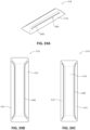
- the sizing feature 606 can comprise, for example, an aperture 608 extending through at least a portion of the at least one wave structure 318 (shown in FIGS. 35A to 37E and 39A to 39E ), a portion of the wave structure 318 having a reduced thickness 610 (shown in FIGS. 38A and 38B ), a dimpled section 612 (shown in FIGS. 40A and 40B ), or any combination thereof.
- At least one of the wave structure 318 can include an aperture 608.
- the aperture 608 can be positioned at least partially on an inner surface 614 of the at least one wave structure 318.
- the aperture 608 can define any shape when viewed from the inner surface 614 of the wave structure 318, such as, for example, a generally polygonal opening, a generally ellipsoidal opening, or a combination thereof.
- the aperture 608 can be ovular (e.g., FIGS. 36A through 36C ).
- the aperture 608 can be pinched (e.g., FIGS. 35A through 35E ) in that the ends 618 are tapered.
- FIGS. 35C and 35E show the wave structure 318 in the assembled state (i.e., after insertion of the posts). It should be understood that in FIGS. 35C and 35E , the apertures 608 are shown exaggerated (i.e., slightly open) in the assembled state and are not drawn to scale. In practice, the apertures 608 may fully close in the assembled state so as to reveal a seemingly continuous inner surface 614 devoid of openings therein.
- a radially innermost surface 614 of the wave structure 318 can act as a parabolic arch, transferring the radial force provided by the posts along a side surface 616 of the wave structure 318 to the undeformed section 316 of the bearing.
- the wave structure 318 is devoid of a continuous parabolic arch, subjecting the wave structure 318 to deflect to the closed, or partially closed, assembled state without transferring significant forces to the undeformed section 316. In such a manner, minimal forces can be transferred to the undeformed section 316 of the wave structure 318 during insertion of the posts into the bearings.
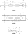
- FIGS. 36A and 36B show another embodiment of the wave structure 318 in the initially unassembled state (i.e., prior to insertion of the posts).
- the aperture 608 is in the open position. In the open position, the radial stiffness of the wave structure 318 is reduced to allow for easier insertion of the posts into the bearings.
- the aperture 608 can extend at least partially along the length of the wave structure 318.
- the aperture 608 can at least partially close, thereby, enhancing stiffness of the wave structure 318.
- FIG. 36C shows the wave structure 318 of FIGS. 36A and 36B in the assembled state (i.e., after insertion of the posts into the bearings).
- the aperture 608 is shown exaggerated (i.e., slightly open) in the assembled state and is not drawn to scale. In practice, the aperture 608 may fully close in the assembled state so as to reveal a continuous inner surface 614 devoid of any opening therein.
- the aperture 608 may substantially close in the assembled state such that a small opening remains along the inner surface 614 of the wave structure 318.
- a radially innermost surface 614 of the wave structure 318 can act as a parabolic arch, transferring the radial force provided by the posts along a side surface 616 of the wave structure 318 to the undeformed section 316 of the bearing.
- the wave structure 318 is devoid of a continuous parabolic arch, subjecting the wave structure 318 to deflect to the closed, or partially closed, assembled state without transferring significant forces to the undeformed section 316. In such a manner, minimal forces can be transferred to the undeformed section 316 of the wave structure 318 during insertion of the posts into the bearings.
- FIGS. 37A, 37B , and 37D show a further embodiment of the wave structure 318 in the initially unassembled state (i.e., prior to insertion of the posts into the bearings).
- the apertures 608 are in the open position. In this position the radial stiffness of the wave structure 318 is reduced to allow for easier insertion of the posts into the bearings.
- the apertures 608 can extend at least partially along the width of the wave structure 318. During insertion of the post into the bearing, the apertures 608 can at least partially close, thereby, enhancing stiffness of the wave structure 318.
- FIGS. 37C and 37E show the wave structure 318 of FIGS. 37A, 37B , and 37D in the assembled state (i.e., after insertion of the posts into the bearings). It should be understood that in FIGS. 37C and 37E , the apertures 608 are shown exaggerated (i.e., slightly open) in the assembled state and are not drawn to scale. In practice, the apertures 608 may fully close in the assembled state so as to reveal a continuous inner surface 614 devoid of any opening therein.
- the apertures 608 may substantially close in the assembled state such that small opening remain along the inner surface 614 of the wave structure 318.
- a radially innermost surface 614 of the wave structure 318 can act as an arch, transferring the radial force provided by the posts along a side surface 616 of the wave structure 318 to the undeformed section 316 of the bearing.
- the wave structure 318 is devoid of a continuous parabolic arch, subjecting the wave structure 318 to deflect to the closed, or partially closed, assembled state without transferring significant forces to the undeformed section 316. In such a manner, minimal forces can be transferred to the undeformed section 316 of the wave structure 318 during insertion of the posts into the bearings.
- At least one wave structure 318 can include an aperture 608 positioned along at least one of the side surfaces 616. In such a manner, the wave structure 318 can be at least partially disconnected from the undeformed portion of the sidewall of the bearing.
- the wave structures 318 can include an aperture along at least three sides. In such a manner, the wave structure can be disconnected from the sidewall along at least a portion of three sides thereof, e.g., a tine. In an embodiment, the tine can be bent or otherwise deflected in a radial direction. This may increase or decrease radial loading of the wave structure 318 as measured on the post.
- the aperture 608 can define any shape when viewed from the side surface 616 of the wave structure 318, such as, for example, a generally polygonal opening, a generally ellipsoidal opening, or a combination thereof.
- the aperture 608 can be ovular. In other embodiments, the aperture 608 can be pinched.
- FIGS. 39A, 39B , and 39D show yet a further embodiment of the wave structure 318 in the initially unassembled state (i.e., prior to insertion of the posts into the bearings).
- the apertures 608 are in the open position. In this position the radial stiffness of the wave structure 318 is reduced to allow for easier insertion of the posts into the bearings.
- the apertures 608 can extend at least partially along the length of the wave structure 318. During insertion of the post into the bearing, the apertures 608 can at least partially close, thereby, enhancing stiffness of the wave structure 318.
- FIGS. 39C and 39E show the wave structure 318 in the assembled state (i.e., after insertion of the posts into the bearings). It should be understood that in FIGS. 39C and 39E , the apertures 608 are shown exaggerated (i.e., slightly open) in the assembled state and are not drawn to scale. In practice, the apertures 608 may fully close in the assembled state so as to reveal a continuous side surface 616 devoid of any opening therein.
- the apertures 608 may substantially close in the assembled state such that small gaps remain along the side surface 616 of the wave structure 318.
- a radially innermost surface 614 of the wave structure 318 can act as an arch, transferring the radial force provided by the posts along a side surface 616 of the wave structure 318 to the undeformed section.
- the wave structure 318 is devoid of a continuous side wall 616, subjecting the wave structure 318 to deflect to the closed, or partially closed, assembled state without transferring significant forces to the undeformed section 316. In such a manner, minimal forces can be transferred to the undeformed section 316 of the wave structure 318 during insertion of the posts into the bearings.
- the aperture 608 can have at least one tapered end 618 when viewed in a direction perpendicular to the aperture 608.
- the tapered end 618 can define an acute angle, A A , which can be less than about 45 degrees, such as less than about 40 degrees, less than about 35 degrees, less than about 30 degrees, less than about 25 degrees, less than about 20 degrees, less than about 15 degrees, or even less than about 10 degrees.
- the aperture 608 can have a maximum length, L A , and a maximum width, W A , as measured perpendicular to L A .
- a ratio of L A :W A can be no less than about 1.0, such as no less than about 1.5, no less than about 2.0, no less than about 2.5, no less than about 3.0, no less than about 4.0, no less than about 5.0, no less than about 6.0, no less than about 7.0, no less than about 8.0, no less than about 9.0, no less than about 10.0, no less than about 15.0, no less than about 20.0, no less than about 25.0, or even no less than about 30.0.
- the ratio of L A :W A can be no greater than about 500, such as no greater than about 400, no greater than about 300, no greater than about 200, no greater than about 100, no greater than about 75, no greater than about 50, or even no greater than about 40.
- the ratio of L A :W A can be within a range of between and including any of the values described above, such as, for example, about 12.0.
- a ratio of L W :L A can be no greater than about 1.25, such as no greater than about 1.0, no greater than about 0.95, no greater than about 0.90, no greater than about 0.85, no greater than about 0.80, no greater than about 0.75, no greater than about 0.70, no greater than about 0.65, or even no greater than about 0.60.
- the ratio of L W :L A can be no less than about 0.01, such as no less than about 0.10, no less than about 0.20, no less than about 0.30, or even no less than about 0.40.
- the ratio of L W :L A can be within a range of between and including any of the values described above, such as, for example, about 0.90.
- a ratio of T P :T UP can be no greater than about 0.99, such as no greater than about 0.95, no greater than about 0.90, no greater than about 0.85, no greater than about 0.80, no greater than about 0.75, no greater than about 0.70, no greater than about 0.65, no greater than about 0.60, no greater than about 0.55, no greater than about 0.50, no greater than about 0.40, no greater than about 0.30, or even no greater than about 0.20.
- the ratio of T P :T UP can be no less than about 0.05, such as no less than about 0.10, no less than about 0.15, or even no less than about 0.20.
- the ratio of T P :T UP can be within a range of between and including any of the values described above, such as, for example, about 0.85.
- the magnitude of difference between the initial unassembled radial stiffness and the assembled radial stiffness can increase while the required assembly force can decrease.
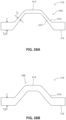
- the wave structure of FIG. 38A can collapse and the portion 610 of the wave structure 318 having a reduced thickness can become thicker.
- the portion 610 of the wave structure 318 having a reduced thickness can have an initial unassembled radial stiffness, S 1 (as shown in FIG. 38A ), and an assembled radial stiffness, S 2 (as shown in FIG. 38B ), wherein S 2 is greater than S 1 .
- a ratio of S 2 :S 1 can be no less than about 1.01, such as no less than about 1.05, no less than about 1.10, no less than about 1.20, no less than about 1.30, no less than about 1.40, no less than about 1.50, no less than about 1.75, or even no less than about 2.00.
- the ratio of A P :A W can be no greater than about 0.99, such as no greater than about 0.98, no greater than about 0.97, no greater than about 0.96, no greater than about 0.95, no greater than about 0.94, no greater than about 0.93, no greater than about 0.92, no greater than about 0.91, or even no greater than about 0.90.
- the ratio of A P :A W can be within a range of between and including any of the values described above, such as, for example, about 0.45.
- the dimpled section 612 can comprise a corrugation 620.
- the corrugation 620 can further comprise a plurality of corrugations.
- the corrugation(s) 620 can be positioned along the inner surface 614 of the wave structure 318 or partially there along.
- the ratio of S 2 :S 1 can be no greater than about 20, such as no greater than about 15, no greater than about 10, no greater than about 5, or even no greater than about 3. Moreover, the ratio of S 2 :S 1 can be within a range of between and including any of the above described values, such as, for example, between about 2.1 and about 2.5.
- the assembly 1 can include guide sleeves 200, 202 adapted to be engaged with one of the first and second posts 100, 102.
- the first guide sleeve 200 can include a locking mechanism 400 and bearing 300.
- the other of the guide sleeves 200, 202 can include the bearing 302 and the component 456.
- the locking mechanism 400 includes a housing 404 having a bore defining an axial cavity 418 there through.
- the axial cavity 418 can have a central axis 420 extending from a bottom end 422 of the locking mechanism 400 to a top end 424 of the locking mechanism 400.
- the housing 404 can be cylindrical, having a height, H H , and a main diameter, D H .
- the central axis 420 can extend parallel with an outer surface 426 of the housing 404.
- the axial cavity 418 can have a diameter, D C , wherein a ratio of D H :D C can be at least 1.1, such as at least 1.2, at least 1.3, at least 1.4, at least 1.5, at least 1.6, at least 1.7, at least 1.8, at least 1.9, at least 2.0, at least 2.5, or even at least 3.
- a ratio of D C :D P can be no greater than 2.0, such as no greater than 1.5, no greater than 1.25, no greater than 1.2, no greater than 1.1, no greater than 1.05, or even no greater than 1.025.
- the ratio of D C :D P can be no less than 1.001, such as no less than 1.005, no less than 1.01, no less than 1.025, no less than 1.05, or even no less than 1.75. Additionally, the ratio of D C :D P can also be within a range between and including any of the ratio values described above.
- the frictional resistance between the posts 100, 102 and the housing 404 of the locking mechanism 400 can increase. The increasing frictional resistance can impact the ease by which an occupant of the vehicle can adjust the head restraint assembly 1.
- the ratio of OD H1 :OD H2 can also be within a range between and including any of the ratio values described above.
- OD H1 :OD H2 can be approximately 2.
- the second cylindrical section 430 can have an outer diameter that is approximately one-half the outer diameter of the first cylindrical section 428.
- the first cylindrical section 428 can have a height, H H1
- the second cylindrical section 430 can have a height, H H2 , wherein a ratio of H H1 :H H2 can be no less than 0.25, such as no less than 0.5, no less than 0.75, no less than 1.0, no less than 1.5, or even no less than 2.0.
- the ratio of H H1 :H H2 can be no greater than 5.0, such as no greater than 4.5, no greater than 4.0, no greater than 3.5, no greater than 3.0, no greater than 2.5, no greater than 2.0, or even no greater than 1.5.
- the ratio of H H1 :H H2 can also be within a range between and including any of the ratio values described above.
- the housing 404 can comprise any suitable material with sufficient rigidity to withstand axial and longitudinal forces.
- the housing 404 can comprise an injection molded polymer.
- the housing 404 can comprise a metal or alloy formed through a machining process.
- the housing 404 can comprise a ceramic or any other suitable material.
- the housing 404 can be formed from a single piece, two pieces, or several pieces joined together by welding, adhesive, fasteners, threading, or any other suitable fastening means.
- the housing 404 can be mated such that the bottom of the first cylindrical section is flush with the top surface 6 of the seat back 4. In this regard, the housing 404 can be partially visible to occupants within the vehicle. In a further aspect, the housing 404 can be mounted above the top surface 6 of the seat back 4.
- the bearings 300, 302 can be adapted to fit within the axial cavity 418 of the housing 404.
- the axial cavity 418 can have an inner diameter, ID AC
- the bearings 300, 302 can have an outer diameter, OD B .
- a ratio of ID AC :OD B can be no greater than 1.20, such as no greater than 1.15, no greater than 1.10, no greater than 1.09, no greater than 1.08, no greater than 1.07, no greater than 1.06, no greater than 1.05, no greater than 1.04, no greater than 1.03, no greater than 1.02, or even no greater than 1.01.
- the ratio of ID AC :OD B can be greater than 1, such as greater than 1.01, greater than 1.02, greater than 1.03, greater than 1.04, greater than 1.05, or even greater than 1.10. Additionally, the ratio of ID AC :OD B can also be within a range between and including any of the ratio values described above.
- the first ends 306 of the bearings 300, 302 can be inserted into the cavity 418 of the housing 404.
- the bearings 300, 302 can be aligned with the locking mechanism 400 and component 456 such that the central axis 420 of the cavity 418 aligns with the central axis 322 of the bearings 300, 302.
- the bearings 300, 302 can further include an engagement structure 326 to secure with the housing 404.
- the guide center axis 306 can be parallel and concomitant with the first center axis 420 of the cavity 418.
- the engagement structure can comprise at least one L-shaped cutout 326 in each of the bearings 300, 302.
- Each of the L-shaped cutouts 326 can have an opening 328 extending axially inward from the first end 306 of the bearing 300, 302; a heel 330 at the base of the opening 328; a sliding lock surface 332 extending from the heel 330; and an end 334 at a terminal side of the sliding lock surface 332.
- An inner surface of the housing 404 can further include at least one tab 408 extending radially inward into the cavity 418, substantially perpendicular to the center axis 420.
- each of the bearings 300, 302 can be aligned such that the tab 408 fits within the opening 328 of the bearings 300, 302.
- the bearings 300, 302 can be urged into the cavity 418 until the heel 330 of each L-shaped cutout 326 makes contact with each tab 408.
- the bearings 300, 302 can be rotated such that the tabs 408 translates on the sliding lock surface 332 until the tabs 408 contact the end 334 of the L-shaped cutout 326.
- the bearings 300, 302 can be secured to the housing 404 in any method recognizable to one having ordinary skill in the art.
- the bearings 300, 302 can threadably engage to the housing 404.
- Each of the bearings 300, 302 can include a first thread and the housing 404 can include a complementary second thread.
- the bearings 300, 302 can be secured to the housing 404 by an adhesive.
- the bearings 300, 302 can be secured to the housing 404 by an interference fit.
- the bearings 300, 302 can be secured to the housing 404 by a pin or a fastener.
- the bearings 300, 302 can be secured to the housing 404 by a bayonet connection.
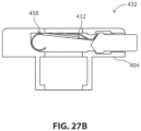
- the locking member 432 can comprise an opening 434 having a central axis 436, and a first and second surface 438 and 440. Moreover, the locking member 432 can additionally include at least one biasing element 442 extending from the second surface 440 of the locking member 432.
- the biasing element 442 can be adapted to provide a biasing force relatively parallel with the central axis 436.
- the biasing element 442 can be a spring.
- the biasing element 442 can be a leaf spring extending from the second surface 440 of the locking member 432. In a particular aspect, the leaf spring 442 can be formed integrally from the locking member 432.
- the locking member 432 can further include a distal flange 446 projecting from the locking member 432 at an angle, A F .
- a F can be no less than 45 degrees, such as no less than 50 degrees, no less than 55 degrees, no less than 60 degrees, no less than 65 degrees, no less than 70 degrees, no less than 75 degrees, no less than 80 degrees, no less than 85 degrees, no less than 90 degrees, no less than 95 degrees, no less than 100 degrees, no less than 105 degrees, or even no less than 110 degrees.
- a F can be no greater than 170 degrees, such as no greater than 165 degrees, no greater than 160 degrees, no greater than 155 degrees, no greater than 150 degrees, no greater than 145 degrees, no greater than 140 degrees, no greater than 135 degrees, no greater than 130 degrees, no greater than 125 degrees, no greater than 120 degrees, no greater than 115 degrees, no greater than 110 degrees, no greater than 105 degrees, no greater than 100 degrees, no greater than 95 degrees, or even no greater than 90 degrees. Additionally, A F can also be within a range between and including any of the values described above.
- the locking member 432 can also include a lever 448 extending from the first surface 438 of the locking member 432 opposite the flange 446.
- the lever 448 can be formed by rolling an edge of the locking member 432 over on itself.
- the lever 448 can be integrally formed from the locking member 432, increasing strength of the lever 448 while simultaneously reducing the need for a weld or joint.
- the lever 448 can be formed from a material that is attached to the locking member by welding or adhesive.
- the lever 448 can be formed similar to the flange 446.
- the lever 448 can be formed from the surface of the locking member 432 that is bent at a substantially right-angle.
- the lever 448 is adapted to cant the locking member 432 at an angle, A C , when positioned there below.
- the locking member 432 having the relative canting angle, A C , can be adapted to facilitate an interference fit with at least one of the posts 100, 102.
- the locking member 432 can prevent axial translation of the post 100 or 102 within the opening 434.
- a C can be no less than 1 degree, such as no less than 2 degrees, no less than 3 degrees, no less than 4 degrees, no less than 5 degrees, no less than 10 degrees, no less than 15 degrees, no less than 20 degrees, no less than 25 degrees, no less than 30 degrees, no less than 35 degrees, or even no less than 40 degrees.
- a C can be no greater than 60 degrees, no greater than 55 degrees, no greater than 50 degrees, no greater than 45 degrees, no greater than 40 degrees, no greater than 35 degrees, no greater than 30 degrees, no greater than 25 degrees, no greater than 20 degrees, no greater than 15 degrees, or even no greater than 10 degrees.
- a C can also be within a range between and including any of the values described above. While A C can be selected to be within the above described range, the value selected is directly dependent on the diameter of the opening 434 and the diameter of the posts 100, 102.
- the locking member 432 When the locking member 432 is seated on a level surface such that the lever 448 forms a point of contact between the locking member 432 and the surface there below, the locking member 432 can have a maximum height, H LM , as defined by the distance between the surface and the top point 458 furthest therefrom.
- the opening 434 of the locking member 432 can have a diameter, D O , wherein D O is greater than D C .
- a ratio of D O :D C is at least 1.05, such as at least 1.1, at least 1.15, at least 1.2, at least 1.25, at least 1.3, at least 1.35, at least 1.4, at least 1.45, or even at least 1.5.
- the ratio of D O :D C is no greater than 2.0, such as no greater than 1.9, no greater than 1.8, no greater than 1.7, no greater than 1.6, no greater than 1.5, no greater than 1.4, no greater than 1.3, no greater than 1.2, or even no greater than 1.1.
- the ratio of D O :D C can also be within a range between and including any of the values described above. The ratio of D O :D C will be obvious to one having ordinary skill in the art in light of this disclosure.
- the locking member 432 can be positioned within a slot 409 in the housing 404.
- the slot 409 can be oriented substantially perpendicular to the central axis 420 of the cavity 418.
- the slot 409 can have a top wall 412 and a bottom wall 414 and can include three side walls 416.
- the slot 409 can form a substantially rectangular cuboid having a height, H S , a length L S , and a width, W S .
- the slot 409 can include a top wall 410, a bottom wall 412 and can include at least two side walls 416.
- the locking member 432 is visible through the housing 404 from the two sides of the cuboidal slot 409 not including side walls 416.
- a ratio of H S :H LM can be at least 0.9, such as at least 0.95, at least 1.0, at least 1.01, at least 1.02, at least 1.03, at least 1.04, at least 1.05, at least 1.06, at least 1.07, at least 1.08, at least 1.09, at least 1.10, at least 1.15, or even at least 1.2.
- the ratio of H S :H LM can be no greater than 1.4, such as no greater than 1.35, no greater than 1.3, no greater than 1.25, no greater than 1.2, no greater than 1.15, no greater than 1.1, no greater than 1.05, no greater than 1.04, no greater than 1.03, no greater than 1.02, no greater than 1.01, or even no greater than 1.0.
- the ratio of H S :H LM can also be within a range between and including any of the values described above.
- the ratio of H S :H LM has a value of less than 1.0
- the locking member 432 can be compressed within the slot 409 by the top wall 412 of the slot 409, such that the top point 458 is urged towards the lever 448.
- the application of force on the top point 458 towards the lever 448 may enhance the gripping properties of the locking member 432 with the posts 100, 102.
- the relative gripping power exhibited by the locking member 432 against the post 100 or 102 disposed of therein can increase.
- the locking member 432 can be angularly positioned relative to the central axis 420, resulting in a relative acute angle formed between the central axis 420 and the central axis 436.
- This acute angle can be equal to the canting angle, A C , of the locking member 432.
- a C1 the angle between the central axes 420 and 436 increases an equal value.
- the locking member 432 can be adapted to form an interference fit with the posts 100, 102. This interference fit can prevent the posts 100, 102 from translating along the central axis 436 of the cavity 418 in either vertical direction (i.e., upward or downward).
- the locking member 432 can be adapted such that the central axis 420 of the cavity 418 substantially aligns with the central axis 436 of the opening 434. At this position, the locking member 432 is canted at a lesser angle, A C2 . In this position, the locking member 432 can be adapted to permit the posts 100, 102 to translate within the cavity 418 in either vertical direction (i.e., upward or downward). Angle A C2 is shown in FIG. 31 .
- the locking mechanism 400 can further comprise an actuating member 450 engaged at least partially in the slot 409 between the housing 404 and the flange 446 of the locking member 432.
- the actuating member 450 can be adapted to translate in a direction substantially perpendicular to the central axis 420. As the actuating member 450 translates radially inward towards the central axis 420 the actuating member 450 can engage the flange 446 of the locking mechanism 400, angularly rotating the locking member 432 around the lever 448 and displacing the flange 446 in a direction parallel with the central axis 420. As the locking member 432 rotates around the lever 448 the angle, A C , decreases, causing the first and second axes 420 and 436 to become more closely aligned.
- the actuating member 450 can comprise a plunger having an angled plunger face 454 adapted to engage with the flange 446 of the locking member 432.
- the plunger face 454 can have a plunger angle, A P .
- a P can be greater than 30 degrees, such as greater than 35 degrees, greater than 40 degrees, greater than 45 degrees, greater than 50 degrees, greater than 55 degrees, greater than 60 degrees, greater than 65 degrees, greater than 70 degrees, greater than 75 degrees, greater than 80 degrees, greater than 85 degrees, greater than 90 degrees, greater than 95 degrees, or even greater than 100 degrees.
- the locking member 432 is in a first position when angle A C1 is greatest. Conversely, it can be understood that the locking member 432 is in a second position when angle A C2 is smallest.
- one of the posts 100, 102 can be adapted to fit simultaneously within the cavity 418 of the housing 404 and the opening 434 of the locking member 432.
- the locking member 432 can prevent the posts 100, 102 from translating in a first direction, as represented in FIG. 1 by line 500.
- the locking mechanism 400 can prohibit the translation of the posts 100, 102 in the first direction (represented by line 500) upon the application of five seconds of applied force in the first direction of 500 Newtons (N).
- the posts 100, 102 can be prohibited from translating in the first direction by an interference formed between the cavity 418 and the opening 434 of the locking member 432. More specifically, the interference can be formed between the central axes 420 and 436. As the central axis 420 of the cavity 418 cants relative to the central axis 436 of the opening 434, a biting edge 458 of the of the locking member 432 can engage the post 100, 102. It can be understood that the biting edge 458 can prevent axial translation of the posts 100, 102 through the opening 434 in the direction in which the locking member 432 is oriented. In a particular embodiment, the posts 100, 102 can be prohibited from translating axially in a direction towards the biting edge 106 upon application of a force of less than 500 N, as sustained for five seconds.
- biting edge 458 can comprise teeth extending radially inward.
- biting edge 458 can comprise a roughened surface.
- biting edge 458 can be have a sharp lip capable of forming a groove or channel in the outer surface of the posts 100, 102.
- biting edge 458 can comprise a rolled over surface 460 of the locking member 432.
- the locking member 432 can be adapted to prevent relative axial translation of the posts 100, 102 within the cavity 418 of the housing 404 in a first direction (represented by line 500) upon the application of force in the first direction of no greater than 500 N, while simultaneously permitting translation of the posts 100, 102 within the cavity 418 of the housing 404 upon the application of a force in the second direction (represented by line 502) of no greater than 45 N.
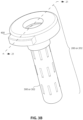
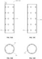
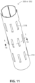
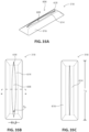
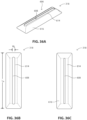
- the locking mechanism 400 can be attached to a bearing 700 having a generally cylindrical sidewall 702 and one or more elongated fingers 704 each at least partially coupled to the generally cylindrical sidewall 702.
- Each elongated finger 704 can define an aspect ratio as measured by a length thereof in the axial direction as compared to a width thereof, as measured in the circumferential direction.
- at least one of the elongated fingers 704 can have an aspect ratio of at least 1.1:1, such as at least 1.5:1, at least 2:1, at least 3:1, at least 4:1, at least 5:1, or even at least 10:1.
- the aspect ratio can be no greater than 100:1, such as no greater than 50:1, or even no greater than 25:1.
- At least one elongated fingers 704 can be monolithic with the generally cylindrical sidewall 702, i.e., the elongated finger 704 has a unitary construction with the generally cylindrical sidewall 702.
- at least one of the elongated fingers 704 may comprise a separate component attached to the generally cylindrical sidewall 702.
- the separate component may be attached to the generally cylindrical sidewall 702 by an adhesive, welding, crimping, or any other suitable process recognizable in the art.
- the elongated fingers 704 may be formed by a process, such as, for example, stamping, pressing, or cutting. In an embodiment, at least one of the elongated fingers 704 may be formed prior to formation of the generally cylindrical sidewall 702, e.g., prior to rolling a flat sheet to form the generally cylindrical sidewall 702. In an embodiment, at least one of the elongated fingers 704 may be formed after formation of the generally cylindrical sidewall 702, e.g., after rolling a flat sheet to form the generally cylindrical sidewall 702.
- At least two of the elongated fingers 704 have the same geometric shape or size as compared to each other. In a further embodiment, all of the elongated fingers 704 may have the same geometric shape or size as compared to each other. In another embodiment, at least two of the elongated fingers 704 may have different geometric shapes or sizes as compared to each other. In a further embodiment, all of the elongated fingers 704 may have different geometric shapes or sizes as compared to each other.
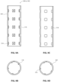
- the bearing 700 can include a plurality of elongated fingers 704 at least partially coupled to the generally cylindrical sidewall 702.
- the plurality of fingers 704 can include an (first) elongated finger 708 and an (second) elongated finger 710.
- the plurality of elongated fingers 704 can be spaced apart in a circumferential direction around the generally cylindrical sidewall 702. In a more particular embodiment, each of the plurality of elongated fingers 704 may be spaced apart from one another an equal distance as measured around a circumference of the generally cylindrical sidewall 702.
- the elongated fingers 708 and 710 can extend from the generally cylindrical sidewall 702 in different directions. In a more particular embodiment, the elongated fingers 708 and 710 can extend in opposite directions. In an embodiment, the elongated fingers 708 and 710 may extend away from each other, i.e., the connected sides 706 ( FIG. 42 ) of the elongated fingers 708 and 710 are closer together than any other portion of the elongated fingers 708 and 710.
- the elongated fingers 704 can each define an axial bisecting line.
- the axial bisecting lines of at least two of the elongated fingers 704 can be oriented parallel, i.e., the at least two elongated fingers 704 are oriented parallel to each other.
- all of the elongated fingers 704 can be oriented parallel with respect to each other.
- the elongated fingers 704 can each define a maximum circumferential gap distance, G C , as measured with respect to the generally cylindrical sidewall 702 in a circumferential direction (perpendicular to Line 42-42), and a maximum axial gap distance, G A , as measured with respect to the generally cylindrical sidewall 702 in an axial direction (along Line 42-42).
- G A can be different than G C .
- the maximum axial gap distance, G A can be greater than the maximum circumferential gap distance, G C .
- G A can be at least 105% G C , such as at least 110% G C , at least 120% G C , at least 120% G C , or even at least 145% G C .
- G A can be no greater than 500% G C , such as no greater than 400% G C , no greater than 300% G C , or even no greater than 200% G C .
- At least one of the elongated fingers 704 can cant relative to a central axis 712 of the bearing 700 prior to installation of a post into the bearing 700.
- G C and G A may be equal prior to canting the elongated finger 704 relative to the central axis.
- Each elongated finger 704 can define a radially innermost surface 716 and a bridge portion 718 connecting the radially innermost surface 716 to the generally cylindrical sidewall 702.
- a best fit line of the bridge portion 718 can cant relative to the central axis 712.
- the bridge portion 718 can form an angle 724 with respect to the generally cylindrical sidewall 702, as measured in the unassembled or unloaded state, e.g., prior to installation of a post into the bearing 700.
- the angle 724 between the bridge portion 718 and the generally cylindrical sidewall 702 in the unloaded state can be at least 2°, such as at least 3°, at least 4°, at least 5°, or even at least 10°.
- the angle 724 can be no greater than 45°, such as no greater than 40°, no greater than 35°, no greater than 30°, no greater than 25°, or even no greater than 20°.
- a best fit circle formed by the innermost surfaces 716 of a circumferentially extending row of elongated fingers 704 can have a diameter that is less than an inner diameter of the generally cylindrical sidewall 702, as measured prior to installation of a post into the bearing 700. Upon installation of the post, the diameter of the best fit circle of the innermost surfaces 716 of the circumferentially extending row of elongated fingers 704 can increase.
- each elongated finger 704 can further include an end portion 720 extending radially outward from the innermost surface 716.
- the end portion 720 can extend from the innermost surface 716 opposite the bridge portion 718.
- a portion of the end portion 720 of the elongated finger 704 can extend radially outward beyond an outer surface 722 of the generally cylindrical sidewall 702.
- an outer surface of the end portion 720 can lie along the same plane as the outer surface 722 of the generally cylindrical sidewall 702.
- the outer surface of the end portion 720 can terminate radially inside of the outer surface 722 of the generally cylindrical sidewall 702. Termination of the end portion 720 radially inside of the outer surface 722 may be particularly suitable when the bearing 700 is encased in an outer member (discussed below) that limits radially outward deflection of the end portion 720 beyond the outer surface 722.
- the elongated finger 704 may have a radius of curvature as measured in a circumferential direction of the bearing 700 that is different than a radius of curvature of the generally cylindrical sidewall 702. In a more particular embodiment, the elongated finger 704 may have a larger radius of curvature as compared to the generally cylindrical sidewall 702. In this regard, the elongated finger 704 may appear more planar than the generally cylindrical sidewall 702.
- the substrate can at least partially include a metal. More particularly, the substrate can at least partially include a steel, such as a stainless steel. For example, the substrate can at least partially include a 301 stainless steel. The 301 stainless steel may be annealed, 1 ⁇ 4 hard, 1 ⁇ 2 hard, 3 ⁇ 4 hard, or full hard.
- the low friction material can comprise materials including, for example, a polymer, such as a polyketone, a polyaramid, a polyimide, a polytherimide, a polyphenylene sulfide, a polyetherslfone, a polysulfone, a polypheylene sulfone, a polyamideimide, ultra high molecular weight polyethylene, a fluoropolymer, a polyamide, a polybenzimidazole, or any combination thereof.
- a polymer such as a polyketone, a polyaramid, a polyimide, a polytherimide, a polyphenylene sulfide, a polyetherslfone, a polysulfone, a polypheylene sulfone, a polyamideimide, ultra high molecular weight polyethylene, a fluoropolymer, a polyamide, a polybenzimidazole, or any combination thereof.
- the low friction material includes a polyketone, a polyaramid, a polyimide, a polyetherimide, a polyamideimide, a polyphenylene sulfide, a polyphenylene sulfone, a fluoropolymer, a polybenzimidazole, a derivation thereof, or a combination thereof.
- the low friction material includes a polymer, such as a polyketone, a thermoplastic polyimide, a polyetherimide, a polyphenylene sulfide, a polyether sulfone, a polysulfone, a polyamideimide, a derivative thereof, or a combination thereof.
- the low friction material includes polyketone, such as polyether ether ketone (PEEK), polyether ketone, polyether ketone ketone, polyether ketone ether ketone, a derivative thereof, or a combination thereof.
- the low friction material may be an ultra high molecular weight polyethylene.
- An example fluoropolymer includes fluorinated ethylene propylene (FEP), PTFE, polyvinylidene fluoride (PVDF), perfluoroalkoxy (PFA), a terpolymer of tetrafluoroethylene, hexafluoropropylene, and vinylidene fluoride (THV), polychlorotrifluoroethylene (PCTFE), ethylene tetrafluoroethylene copolymer (ETFE), ethylene chlorotrifluoroethylene copolymer (ECTFE), or any combination thereof.
- Fluoropolymers are used according to particular embodiments
- the generally cylindrical sidewall 702 can have a thickness in a range of 0.2 mm and 25 mm.
- the generally cylindrical sidewall 702 can have a thickness in a range of 0.2 mm and 1 mm, such as in a range of 0.25 mm and 1 mm, in a range of 0.3 mm and 1 mm, in a range of 0.35 mm and 1 mm, in a range of 0.4 mm and 1 mm, in a range of 0.45 mm and 1 mm, in a range of 0.5 mm and 1 mm, in a range of 0.55 mm and 1 mm, in a range of 0.6 mm and 1 mm, in a range of 0.65 mm and 1 mm, in a range of 0.7 mm and 1 mm, in a range of 0.75 mm and 1 mm, in a range of 0.8 mm and 1 mm, in a range of 0.85 mm and 1 mm, in a range of 0.9
- the thickness can be in a range of 0.2 mm and 0.95 mm, such as in a range of 0.2 mm and 0.9 mm, in a range of 0.2 mm and 0.85 mm, in a range of 0.2 mm and 0.8 mm, in a range of 0.2 mm and 0.75 mm, in a range of 0.2 mm and 0.7 mm, in a range of 0.2 mm and 0.65 mm, in a range of 0.2 mm and 0.6 mm, in a range of 0.2 mm and 0.6 mm, in a range of 0.2 mm and 0.55 mm, in a range of 0.2 mm and 0.5 mm, in a range of 0.2 mm and 0.45 mm, in a range of 0.2 mm and 0.4 mm, in a range of 0.2 mm and 0.35 mm, in a range of 0.2 mm and 0.3 mm, or even in a range of 0.2 mm and 0.25 mm.
- the low friction layer can have a thickness in a range of 0.1 mm and 0.4 mm, such as in a range of 0.15 mm and 0.35 mm, or even in a range of 0.2 mm and 0.3 mm.
- the substrate can form all, or nearly all, of the remaining thickness of the generally cylindrical sidewall 702.
- the thickness of the generally cylindrical sidewall 702 may be uniform, i.e., a thickness at a first location of the generally cylindrical sidewall 702 can be equal to a thickness at a second location therealong. In another embodiment, the thickness of the generally cylindrical sidewall 702 may vary, i.e., a thickness at a first location of the generally cylindrical sidewall 702 is different than a thickness at a second location therealong.
- an average thickness of at least one of the elongated fingers 704 can be approximately equal to the thickness of the generally cylindrical sidewall 704.
- the average thickness of the at least one elongated finger 704 may be within 10% of the thickness of the generally cylindrical sidewall 702.
- the average thickness of at least one of the elongated fingers 704 may be different than the thickness of the generally cylindrical sidewall 704, i.e., the average thickness of the elongated finger 704 may be greater than 10% different than the thickness of the generally cylindrical sidewall.
- the bearing 700 can be at least partially encased by a support member (not illustrated).
- the support member can circumscribe at least a portion of the outer surface 722 of the bearing 700.
- the support member may provide support to the bearing 700.
- the support member can include a resilient material.
- the support member can include a polymer.
- a radially outer surface of the end portion 720 of at least one elongated finger 704 can contact an interior surface of the support member. More particularly, the support member can support the end portion 720.
- the elongated finger 704 may dynamically deflect.
- the end portion 720 may slide along the interior surface of the support member.
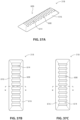
- each bearing 800 can include a generally cylindrical sidewall 806 and at least one elongated finger 808 at least partially coupled to the generally cylindrical sidewall 806.
- the elongated finger 808 can have any similar properties as compared to the elongated finger 704 illustrated in FIGS. 41 to 44 .
- each elongated finger 808 can define a radially innermost surface and a bridge portion connecting the radially innermost surface to the generally cylindrical sidewall 806.
- the bearing 800 includes a plurality of elongated fingers 808 spaced apart in a circumferential direction around the generally cylindrical sidewall 806. More particularly, the plurality of elongated fingers 808 can be spaced apart an equal distance as measured around a circumference of the generally cylindrical sidewall 806.
- the extending features 726 can interlock with the complementary portion of the locking mechanism 400 upon being inserted a distance into the locking mechanism 400.
- the extending features 726 may be radially compressed during a portion of the axial translation of the bearing 700 into the locking mechanism 400 and splay open upon reaching a wider portion therein. The extending features 726 may then seat against a surface of the locking mechanism 400 to prevent disengagement of the bearing 700 therefrom.
- the bearing 700 may include a first plurality of extending features 728 disposed along a first axial end of the generally cylindrical sidewall 702 and a second plurality of extending features 730 disposed along a second axial end of the generally cylindrical sidewall 702.
- the bearing 700 may be reversible in orientation, e.g., the bearing is, or generally is, reflectively symmetrical.
- the second plurality of extending features 730 may permit attachment of additional components to the bearing 700.
- the first and second plurality of extending features 728 and 730 can be circumferentially offset from one another.
- an axial line bisecting one of the extending features of the first plurality of extending features 728 may not overlie one of the extending features of the second plurality of extending features 730.
- an axial line bisecting one of the extending features of the second plurality of extending features 730 may not overlie one of the extending features of the first plurality of extending features 728.
- reaction to radial deflection can be such that deflection of the internal framework 10 of the cushion 8 upon the application of 20 N of force perpendicular to the central axis 420 can be no greater than 5mm.
- the deflection of the framework 10 of the headrest cushion 8 can vary by no greater than 4mm, no greater than 3mm, or even no greater than 2mm.
- Sample 1 comprises a bearing and post in accordance with the present invention.
- the bearing is formed from a multilayer composite (i.e. 3 layers) comprising an outer flouropolymer sliding layer comprising PTFE, a steel substrate and a thin inner sliding layer to prevent metal to metal contact between the bearing and the post.
- the bearing further comprises four wave structures extending radially inward.
- the projections have a radial length of 1.0 mm, as measured from the inner surface of the bearing, and engage the posts at four contact locations.
- the initial diameter of the bearing, as measured by a best fit circle tangent to the inner contact surface of the wave structures is approximately 13.78 mm.
- the post is formed from steel and has a diameter of 14 mm. The normal force is applied against the bearing at a rate of 0.3 mm/min.
- Sample 1 required an average axial force throughout sliding of 12.8 N
- Sample 2 required an average axial force throughout sliding of 39.62 N.
- Sample 1 can freely translate within the bearing upon an average axial force that is less than 33% the average axial force required to translate the post of Sample 2.
Landscapes
- Engineering & Computer Science (AREA)
- Mechanical Engineering (AREA)
- General Engineering & Computer Science (AREA)
- Aviation & Aerospace Engineering (AREA)
- Transportation (AREA)
- Sliding-Contact Bearings (AREA)
- Chair Legs, Seat Parts, And Backrests (AREA)
- Mounting Of Bearings Or Others (AREA)
- Seats For Vehicles (AREA)
- Bearings For Parts Moving Linearly (AREA)
- Support Of The Bearing (AREA)
Claims (11)
- Manchon de guidage d'appui-tête comprenant :une paroi latérale généralement cylindrique (702) ; etun doigt allongé (704) au moins partiellement accouplé à la paroi latérale généralement cylindrique (702) le long d'un premier côté (706) du doigt allongé (704) et détaché de manière continue de la paroi latérale généralement cylindrique (702) le long des côtés restants de celle-ci,dans lequel au moins une partie du doigt allongé (704) est inclinée vers un axe central (712) de la paroi latérale généralement cylindrique (702),dans lequel le doigt allongé (704) comprend une pluralité de doigts allongés (808) espacés autour de la paroi latérale généralement cylindrique (702) dans une direction circonférentielle,caractérisé en ce quela pluralité de doigts allongés (808) sont disposés dans au moins deux rangées s'étendant circonférentiellement.
- Manchon de guidage d'appui-tête selon la revendication 1, comprenant en outre un élément de support disposé radialement à l'extérieur de la paroi latérale généralement cylindrique.
- Manchon de guidage d'appui-tête selon l'une quelconque des revendications précédentes, dans lequel le manchon de guidage d'appui-tête est adapté pour être disposé à l'intérieur d'un siège et recevoir un montant d'appui-tête.
- Manchon de guidage d'appui-tête selon l'une quelconque des revendications précédentes, dans lequel le doigt allongé (704) a un angle initial, tel que mesuré avant l'installation d'un montant d'appui-tête dans la paroi latérale généralement cylindrique (702), et un angle final, tel que mesuré après l'installation du montant dans la paroi latérale généralement cylindrique (702), et dans lequel l'angle initial est différent de l'angle final.
- Manchon de guidage d'appui-tête selon l'une quelconque des revendications précédentes, dans lequel le doigt allongé (704) définit une distance d'espacement axial maximale, telle que mesurée dans une direction axiale entre le doigt allongé (704) et la paroi latérale généralement cylindrique (702), et une distance d'espacement circonférentiel maximale, telle que mesurée dans une direction circonférentielle entre le doigt allongé (704) et la paroi latérale généralement cylindrique (702), et dans lequel la distance d'espacement axial maximale est différente de la distance d'espacement circonférentiel maximale.
- Manchon de guidage d'appui-tête selon la revendication 5, dans lequel la distance d'espacement axial maximale est supérieure à la distance d'espacement circonférentiel maximale.
- Manchon de guidage d'appui-tête selon l'une quelconque des revendications précédentes, dans lequel le doigt allongé (704) comprend :une surface radialement la plus interne (716) ;une première partie s'étendant entre la paroi latérale généralement cylindrique (702) et la surface radialement la plus interne (716) ; etune seconde partie s'étendant à partir de la surface radialement la plus interne opposée à la première partie.
- Manchon de guidage d'appui-tête selon la revendication 1, dans lequel un premier doigt allongé de la pluralité de doigts allongés (808) s'étend depuis la paroi latérale généralement cylindrique (702) dans une première direction, et dans lequel un second doigt allongé de la pluralité de doigts allongés (808) s'étend depuis la paroi latérale généralement cylindrique (702) dans une seconde direction différente de la première direction.
- Manchon de guidage de retenue de tête selon l'une quelconque des revendications 1 et 8, dans lequel au moins deux doigts allongés de la pluralité de doigts allongés (808) sont orientés parallèlement l'un par rapport à l'autre.
- Manchon de guidage de retenue de tête selon l'une quelconque des revendications 1, 8 et 9, dans lequel les doigts allongés (704) ont chacun une surface la plus interne (716), les surfaces les plus internes (716) définissant un cercle d'ajustement optimal, et dans lequel un diamètre du meilleur cercle d'ajustement est inférieur à un diamètre interne de la paroi latérale généralement cylindrique (702) avant l'installation d'un montant d'appui-tête dans le manchon de guidage.
- Manchon de guidage d'appui-tête selon l'une quelconque des revendications précédentes, dans lequel la paroi latérale généralement cylindrique (702) comprend un matériau à faible frottement accouplé à un substrat, le matériau à faible frottement étant choisi dans le groupe constitué par une polycétone, un polyaramide, un polyimide, un polytherimide, un sulfure de polyphénylène, une polyétherbaffone, une polysulfone, une polypheylène sulfone, un polyamideimide, un polyéthylène à poids moléculaire ultra-élevé, un fluoropolymère, un polyamide, un polybenzimidazole, ou leur combinaison quelconque.
Applications Claiming Priority (1)
| Application Number | Priority Date | Filing Date | Title |
|---|---|---|---|
| PCT/US2014/060747 WO2016060660A1 (fr) | 2014-10-15 | 2014-10-15 | Support à utiliser dans un appui-tête coulissant |
Publications (3)
| Publication Number | Publication Date |
|---|---|
| EP3206907A1 EP3206907A1 (fr) | 2017-08-23 |
| EP3206907A4 EP3206907A4 (fr) | 2018-06-20 |
| EP3206907B1 true EP3206907B1 (fr) | 2023-12-13 |
Family
ID=55747049
Family Applications (1)
| Application Number | Title | Priority Date | Filing Date |
|---|---|---|---|
| EP14903940.6A Active EP3206907B1 (fr) | 2014-10-15 | 2014-10-15 | Support à utiliser dans un appui-tête coulissant |
Country Status (6)
| Country | Link |
|---|---|
| EP (1) | EP3206907B1 (fr) |
| JP (1) | JP6458141B2 (fr) |
| KR (1) | KR101958631B1 (fr) |
| CN (1) | CN107000618B (fr) |
| PL (1) | PL3206907T3 (fr) |
| WO (1) | WO2016060660A1 (fr) |
Families Citing this family (11)
| Publication number | Priority date | Publication date | Assignee | Title |
|---|---|---|---|---|
| CA2916006C (fr) | 2013-06-29 | 2018-01-16 | Saint-Gobain Performance Plastics Corporation | Support a utiliser dans un appui-tete coulissant |
| ES2983698T3 (es) * | 2017-03-31 | 2024-10-24 | Saint Gobain Performance Plastics Pampus Gmbh | Ensamblaje con anillo para control de desplazamiento de componentes |
| KR20230003583A (ko) * | 2017-07-14 | 2023-01-06 | 생―고뱅 퍼포먼스 플라스틱스 팜푸스 게엠베하 | 클립, 클립 조립체 및 이들을 제조하고 이용하기 위한 방법 |
| CN107791914B (zh) * | 2017-09-08 | 2023-08-22 | 安道拓鱼复(重庆)汽车部件有限公司 | 两向调节按钮式汽车座椅头枕 |
| US10926789B2 (en) | 2017-12-29 | 2021-02-23 | Saint-Gobain Performance Plastics Rencol Limited | Steering assembly |
| CN111565971B (zh) * | 2017-12-29 | 2022-11-25 | 圣戈班性能塑料万科有限公司 | 用于座椅靠背组件中的轴承 |
| CA3160529A1 (fr) * | 2019-11-07 | 2021-05-14 | Saint-Gobain Performance Plastics Rencol Limited | Paliers electroconducteurs |
| WO2021113599A1 (fr) | 2019-12-06 | 2021-06-10 | Saint-Gobain Performance Plastics Corporation | Palier à bride, assemblage, et procédé de fabrication et d'utilisation de celui-ci |
| KR102765344B1 (ko) * | 2020-01-16 | 2025-02-13 | 생-고뱅 퍼포먼스 플라스틱스 렌콜 리미티드 | 조향 조립용 베어링 |
| JP2024520214A (ja) | 2021-07-02 | 2024-05-22 | サン-ゴバン パフォーマンス プラスチックス パンプス ゲゼルシャフト ミット ベシュレンクテル ハフツング | フランジ付き軸受、アセンブリ、並びにその製造方法及び使用方法 |
| KR20240124302A (ko) | 2021-12-21 | 2024-08-16 | 생-고뱅 퍼포먼스 플라스틱스 코포레이션 | 리브를 갖는 전기 전도성 베어링, 및 이를 제조 및 사용하는 방법 |
Family Cites Families (14)
| Publication number | Priority date | Publication date | Assignee | Title |
|---|---|---|---|---|
| JP3475320B2 (ja) * | 1997-09-24 | 2003-12-08 | 日本テクニカ株式会社 | ヘッドレストサポート |
| US6099077A (en) * | 1998-10-27 | 2000-08-08 | Centura Group, Inc. | Head restraint assembly for motor vehicle |
| US6761409B2 (en) * | 2002-05-03 | 2004-07-13 | John R. Ford | Head restraint guide sleeve |
| FR2877287B1 (fr) * | 2004-10-28 | 2007-01-26 | Cera | Ensemble de guidage en translation d'une tige d'appui-tete comprenant un organe elastique de limitation du jeu |
| JP4854200B2 (ja) * | 2005-01-21 | 2012-01-18 | 日本テクニカ株式会社 | ヘッドレストサポート |
| JP2010069036A (ja) * | 2008-09-19 | 2010-04-02 | Tachi S Co Ltd | 管状ヘッドレスト・ホルダー |
| JP4335297B1 (ja) * | 2008-12-18 | 2009-09-30 | 備前発条株式会社 | ヘッドレストステー支持具及びヘッドレストステー支持構造 |
| KR101108273B1 (ko) * | 2009-07-13 | 2012-01-31 | 주식회사 우보테크 | 헤드레스트 높이조절장치용 가이드 |
| CN201633580U (zh) * | 2010-04-28 | 2010-11-17 | 上海通用汽车有限公司 | 头枕导套和使用该头枕导套的座椅 |
| KR101304673B1 (ko) * | 2011-12-19 | 2013-09-06 | 쌍용자동차 주식회사 | 자동차 헤드레스트의 유동 및 소음방지용 지지봉가이드 |
| KR101836503B1 (ko) * | 2012-02-01 | 2018-03-08 | 현대자동차주식회사 | 헤드레스트 가이드 |
| KR20130112510A (ko) * | 2012-04-04 | 2013-10-14 | 동광리어유한회사 | 차량용 헤드레스트 및 슬리브 결합구조 |
| KR101393789B1 (ko) * | 2012-09-06 | 2014-05-12 | 현대자동차주식회사 | 헤드레스트 폴가이드 |
| CN203142447U (zh) * | 2013-02-28 | 2013-08-21 | 长城汽车股份有限公司 | 头枕导向装置和带有该头枕导向装置的汽车座椅 |
-
2014
- 2014-10-15 WO PCT/US2014/060747 patent/WO2016060660A1/fr not_active Ceased
- 2014-10-15 JP JP2017519528A patent/JP6458141B2/ja active Active
- 2014-10-15 CN CN201480083602.6A patent/CN107000618B/zh active Active
- 2014-10-15 KR KR1020177012464A patent/KR101958631B1/ko active Active
- 2014-10-15 PL PL14903940.6T patent/PL3206907T3/pl unknown
- 2014-10-15 EP EP14903940.6A patent/EP3206907B1/fr active Active
Also Published As
| Publication number | Publication date |
|---|---|
| KR20170068537A (ko) | 2017-06-19 |
| WO2016060660A1 (fr) | 2016-04-21 |
| CN107000618B (zh) | 2020-08-07 |
| JP6458141B2 (ja) | 2019-01-23 |
| EP3206907A1 (fr) | 2017-08-23 |
| CN107000618A (zh) | 2017-08-01 |
| EP3206907A4 (fr) | 2018-06-20 |
| PL3206907T3 (pl) | 2024-04-15 |
| JP2017536863A (ja) | 2017-12-14 |
| KR101958631B1 (ko) | 2019-03-15 |
Similar Documents
| Publication | Publication Date | Title |
|---|---|---|
| US10414311B2 (en) | Bearing for use in sliding head restraint | |
| EP3206907A1 (fr) | Support à utiliser dans un appui-tête coulissant | |
| JP6005068B2 (ja) | 転がり軸受けケージセグメント、転がり軸受けケージおよび転がり軸受けケージの組立て法 | |
| KR101701761B1 (ko) | 베어링 조립체 | |
| EP3189244B1 (fr) | Anneau de tolerance | |
| CN107654651A (zh) | 密封组件和该密封组件的制造方法 | |
| US20190180960A1 (en) | Indexed rotary switch |
Legal Events
| Date | Code | Title | Description |
|---|---|---|---|
| STAA | Information on the status of an ep patent application or granted ep patent |
Free format text: STATUS: THE INTERNATIONAL PUBLICATION HAS BEEN MADE |
|
| PUAI | Public reference made under article 153(3) epc to a published international application that has entered the european phase |
Free format text: ORIGINAL CODE: 0009012 |
|
| STAA | Information on the status of an ep patent application or granted ep patent |
Free format text: STATUS: REQUEST FOR EXAMINATION WAS MADE |
|
| 17P | Request for examination filed |
Effective date: 20170504 |
|
| AK | Designated contracting states |
Kind code of ref document: A1 Designated state(s): AL AT BE BG CH CY CZ DE DK EE ES FI FR GB GR HR HU IE IS IT LI LT LU LV MC MK MT NL NO PL PT RO RS SE SI SK SM TR |
|
| AX | Request for extension of the european patent |
Extension state: BA ME |
|
| DAX | Request for extension of the european patent (deleted) | ||
| REG | Reference to a national code |
Ref country code: DE Ref legal event code: R079 Free format text: PREVIOUS MAIN CLASS: B60N0002480000 Ipc: A47C0007380000 |
|
| A4 | Supplementary search report drawn up and despatched |
Effective date: 20180518 |
|
| RIC1 | Information provided on ipc code assigned before grant |
Ipc: A47C 7/38 20060101AFI20180514BHEP Ipc: F16C 29/02 20060101ALI20180514BHEP |
|
| STAA | Information on the status of an ep patent application or granted ep patent |
Free format text: STATUS: EXAMINATION IS IN PROGRESS |
|
| 17Q | First examination report despatched |
Effective date: 20211208 |
|
| GRAP | Despatch of communication of intention to grant a patent |
Free format text: ORIGINAL CODE: EPIDOSNIGR1 |
|
| STAA | Information on the status of an ep patent application or granted ep patent |
Free format text: STATUS: GRANT OF PATENT IS INTENDED |
|
| INTG | Intention to grant announced |
Effective date: 20230706 |
|
| GRAS | Grant fee paid |
Free format text: ORIGINAL CODE: EPIDOSNIGR3 |
|
| GRAA | (expected) grant |
Free format text: ORIGINAL CODE: 0009210 |
|
| STAA | Information on the status of an ep patent application or granted ep patent |
Free format text: STATUS: THE PATENT HAS BEEN GRANTED |
|
| AK | Designated contracting states |
Kind code of ref document: B1 Designated state(s): AL AT BE BG CH CY CZ DE DK EE ES FI FR GB GR HR HU IE IS IT LI LT LU LV MC MK MT NL NO PL PT RO RS SE SI SK SM TR |
|
| REG | Reference to a national code |
Ref country code: GB Ref legal event code: FG4D |
|
| REG | Reference to a national code |
Ref country code: CH Ref legal event code: EP |
|
| REG | Reference to a national code |
Ref country code: DE Ref legal event code: R096 Ref document number: 602014089110 Country of ref document: DE |
|
| REG | Reference to a national code |
Ref country code: IE Ref legal event code: FG4D |
|
| P01 | Opt-out of the competence of the unified patent court (upc) registered |
Effective date: 20231211 |
|
| PG25 | Lapsed in a contracting state [announced via postgrant information from national office to epo] |
Ref country code: GR Free format text: LAPSE BECAUSE OF FAILURE TO SUBMIT A TRANSLATION OF THE DESCRIPTION OR TO PAY THE FEE WITHIN THE PRESCRIBED TIME-LIMIT Effective date: 20240314 |
|
| REG | Reference to a national code |
Ref country code: LT Ref legal event code: MG9D |
|
| PG25 | Lapsed in a contracting state [announced via postgrant information from national office to epo] |
Ref country code: LT Free format text: LAPSE BECAUSE OF FAILURE TO SUBMIT A TRANSLATION OF THE DESCRIPTION OR TO PAY THE FEE WITHIN THE PRESCRIBED TIME-LIMIT Effective date: 20231213 |
|
| REG | Reference to a national code |
Ref country code: NL Ref legal event code: MP Effective date: 20231213 |
|
| PG25 | Lapsed in a contracting state [announced via postgrant information from national office to epo] |
Ref country code: ES Free format text: LAPSE BECAUSE OF FAILURE TO SUBMIT A TRANSLATION OF THE DESCRIPTION OR TO PAY THE FEE WITHIN THE PRESCRIBED TIME-LIMIT Effective date: 20231213 |
|
| PG25 | Lapsed in a contracting state [announced via postgrant information from national office to epo] |
Ref country code: LT Free format text: LAPSE BECAUSE OF FAILURE TO SUBMIT A TRANSLATION OF THE DESCRIPTION OR TO PAY THE FEE WITHIN THE PRESCRIBED TIME-LIMIT Effective date: 20231213 Ref country code: GR Free format text: LAPSE BECAUSE OF FAILURE TO SUBMIT A TRANSLATION OF THE DESCRIPTION OR TO PAY THE FEE WITHIN THE PRESCRIBED TIME-LIMIT Effective date: 20240314 Ref country code: ES Free format text: LAPSE BECAUSE OF FAILURE TO SUBMIT A TRANSLATION OF THE DESCRIPTION OR TO PAY THE FEE WITHIN THE PRESCRIBED TIME-LIMIT Effective date: 20231213 Ref country code: BG Free format text: LAPSE BECAUSE OF FAILURE TO SUBMIT A TRANSLATION OF THE DESCRIPTION OR TO PAY THE FEE WITHIN THE PRESCRIBED TIME-LIMIT Effective date: 20240313 |
|
| REG | Reference to a national code |
Ref country code: AT Ref legal event code: MK05 Ref document number: 1639691 Country of ref document: AT Kind code of ref document: T Effective date: 20231213 |
|
| PG25 | Lapsed in a contracting state [announced via postgrant information from national office to epo] |
Ref country code: NL Free format text: LAPSE BECAUSE OF FAILURE TO SUBMIT A TRANSLATION OF THE DESCRIPTION OR TO PAY THE FEE WITHIN THE PRESCRIBED TIME-LIMIT Effective date: 20231213 |
|
| PG25 | Lapsed in a contracting state [announced via postgrant information from national office to epo] |
Ref country code: SE Free format text: LAPSE BECAUSE OF FAILURE TO SUBMIT A TRANSLATION OF THE DESCRIPTION OR TO PAY THE FEE WITHIN THE PRESCRIBED TIME-LIMIT Effective date: 20231213 Ref country code: RS Free format text: LAPSE BECAUSE OF FAILURE TO SUBMIT A TRANSLATION OF THE DESCRIPTION OR TO PAY THE FEE WITHIN THE PRESCRIBED TIME-LIMIT Effective date: 20231213 Ref country code: NO Free format text: LAPSE BECAUSE OF FAILURE TO SUBMIT A TRANSLATION OF THE DESCRIPTION OR TO PAY THE FEE WITHIN THE PRESCRIBED TIME-LIMIT Effective date: 20240313 Ref country code: NL Free format text: LAPSE BECAUSE OF FAILURE TO SUBMIT A TRANSLATION OF THE DESCRIPTION OR TO PAY THE FEE WITHIN THE PRESCRIBED TIME-LIMIT Effective date: 20231213 Ref country code: LV Free format text: LAPSE BECAUSE OF FAILURE TO SUBMIT A TRANSLATION OF THE DESCRIPTION OR TO PAY THE FEE WITHIN THE PRESCRIBED TIME-LIMIT Effective date: 20231213 Ref country code: HR Free format text: LAPSE BECAUSE OF FAILURE TO SUBMIT A TRANSLATION OF THE DESCRIPTION OR TO PAY THE FEE WITHIN THE PRESCRIBED TIME-LIMIT Effective date: 20231213 |
|
| PG25 | Lapsed in a contracting state [announced via postgrant information from national office to epo] |
Ref country code: IS Free format text: LAPSE BECAUSE OF FAILURE TO SUBMIT A TRANSLATION OF THE DESCRIPTION OR TO PAY THE FEE WITHIN THE PRESCRIBED TIME-LIMIT Effective date: 20240413 |
|
| PG25 | Lapsed in a contracting state [announced via postgrant information from national office to epo] |
Ref country code: AT Free format text: LAPSE BECAUSE OF FAILURE TO SUBMIT A TRANSLATION OF THE DESCRIPTION OR TO PAY THE FEE WITHIN THE PRESCRIBED TIME-LIMIT Effective date: 20231213 |
|
| PG25 | Lapsed in a contracting state [announced via postgrant information from national office to epo] |
Ref country code: SK Free format text: LAPSE BECAUSE OF FAILURE TO SUBMIT A TRANSLATION OF THE DESCRIPTION OR TO PAY THE FEE WITHIN THE PRESCRIBED TIME-LIMIT Effective date: 20231213 |
|
| PG25 | Lapsed in a contracting state [announced via postgrant information from national office to epo] |
Ref country code: SM Free format text: LAPSE BECAUSE OF FAILURE TO SUBMIT A TRANSLATION OF THE DESCRIPTION OR TO PAY THE FEE WITHIN THE PRESCRIBED TIME-LIMIT Effective date: 20231213 Ref country code: SK Free format text: LAPSE BECAUSE OF FAILURE TO SUBMIT A TRANSLATION OF THE DESCRIPTION OR TO PAY THE FEE WITHIN THE PRESCRIBED TIME-LIMIT Effective date: 20231213 Ref country code: RO Free format text: LAPSE BECAUSE OF FAILURE TO SUBMIT A TRANSLATION OF THE DESCRIPTION OR TO PAY THE FEE WITHIN THE PRESCRIBED TIME-LIMIT Effective date: 20231213 Ref country code: IS Free format text: LAPSE BECAUSE OF FAILURE TO SUBMIT A TRANSLATION OF THE DESCRIPTION OR TO PAY THE FEE WITHIN THE PRESCRIBED TIME-LIMIT Effective date: 20240413 Ref country code: EE Free format text: LAPSE BECAUSE OF FAILURE TO SUBMIT A TRANSLATION OF THE DESCRIPTION OR TO PAY THE FEE WITHIN THE PRESCRIBED TIME-LIMIT Effective date: 20231213 Ref country code: AT Free format text: LAPSE BECAUSE OF FAILURE TO SUBMIT A TRANSLATION OF THE DESCRIPTION OR TO PAY THE FEE WITHIN THE PRESCRIBED TIME-LIMIT Effective date: 20231213 |
|
| PG25 | Lapsed in a contracting state [announced via postgrant information from national office to epo] |
Ref country code: PT Free format text: LAPSE BECAUSE OF FAILURE TO SUBMIT A TRANSLATION OF THE DESCRIPTION OR TO PAY THE FEE WITHIN THE PRESCRIBED TIME-LIMIT Effective date: 20240415 |
|
| PG25 | Lapsed in a contracting state [announced via postgrant information from national office to epo] |
Ref country code: PT Free format text: LAPSE BECAUSE OF FAILURE TO SUBMIT A TRANSLATION OF THE DESCRIPTION OR TO PAY THE FEE WITHIN THE PRESCRIBED TIME-LIMIT Effective date: 20240415 |
|
| REG | Reference to a national code |
Ref country code: DE Ref legal event code: R097 Ref document number: 602014089110 Country of ref document: DE |
|
| PG25 | Lapsed in a contracting state [announced via postgrant information from national office to epo] |
Ref country code: DK Free format text: LAPSE BECAUSE OF FAILURE TO SUBMIT A TRANSLATION OF THE DESCRIPTION OR TO PAY THE FEE WITHIN THE PRESCRIBED TIME-LIMIT Effective date: 20231213 |
|
| PLBE | No opposition filed within time limit |
Free format text: ORIGINAL CODE: 0009261 |
|
| STAA | Information on the status of an ep patent application or granted ep patent |
Free format text: STATUS: NO OPPOSITION FILED WITHIN TIME LIMIT |
|
| PG25 | Lapsed in a contracting state [announced via postgrant information from national office to epo] |
Ref country code: SI Free format text: LAPSE BECAUSE OF FAILURE TO SUBMIT A TRANSLATION OF THE DESCRIPTION OR TO PAY THE FEE WITHIN THE PRESCRIBED TIME-LIMIT Effective date: 20231213 |
|
| PG25 | Lapsed in a contracting state [announced via postgrant information from national office to epo] |
Ref country code: SI Free format text: LAPSE BECAUSE OF FAILURE TO SUBMIT A TRANSLATION OF THE DESCRIPTION OR TO PAY THE FEE WITHIN THE PRESCRIBED TIME-LIMIT Effective date: 20231213 Ref country code: DK Free format text: LAPSE BECAUSE OF FAILURE TO SUBMIT A TRANSLATION OF THE DESCRIPTION OR TO PAY THE FEE WITHIN THE PRESCRIBED TIME-LIMIT Effective date: 20231213 |
|
| 26N | No opposition filed |
Effective date: 20240916 |
|
| REG | Reference to a national code |
Ref country code: CH Ref legal event code: PL |
|
| GBPC | Gb: european patent ceased through non-payment of renewal fee |
Effective date: 20241015 |
|
| PG25 | Lapsed in a contracting state [announced via postgrant information from national office to epo] |
Ref country code: MC Free format text: LAPSE BECAUSE OF FAILURE TO SUBMIT A TRANSLATION OF THE DESCRIPTION OR TO PAY THE FEE WITHIN THE PRESCRIBED TIME-LIMIT Effective date: 20231213 |
|
| PG25 | Lapsed in a contracting state [announced via postgrant information from national office to epo] |
Ref country code: GB Free format text: LAPSE BECAUSE OF NON-PAYMENT OF DUE FEES Effective date: 20241015 |
|
| PG25 | Lapsed in a contracting state [announced via postgrant information from national office to epo] |
Ref country code: LU Free format text: LAPSE BECAUSE OF NON-PAYMENT OF DUE FEES Effective date: 20241015 Ref country code: BE Free format text: LAPSE BECAUSE OF NON-PAYMENT OF DUE FEES Effective date: 20241031 |
|
| PG25 | Lapsed in a contracting state [announced via postgrant information from national office to epo] |
Ref country code: CH Free format text: LAPSE BECAUSE OF NON-PAYMENT OF DUE FEES Effective date: 20241031 |
|
| REG | Reference to a national code |
Ref country code: BE Ref legal event code: MM Effective date: 20241031 |
|
| PG25 | Lapsed in a contracting state [announced via postgrant information from national office to epo] |
Ref country code: FI Free format text: LAPSE BECAUSE OF FAILURE TO SUBMIT A TRANSLATION OF THE DESCRIPTION OR TO PAY THE FEE WITHIN THE PRESCRIBED TIME-LIMIT Effective date: 20231213 |
|
| PGFP | Annual fee paid to national office [announced via postgrant information from national office to epo] |
Ref country code: TR Payment date: 20250925 Year of fee payment: 12 Ref country code: IT Payment date: 20250923 Year of fee payment: 12 Ref country code: PL Payment date: 20250924 Year of fee payment: 12 |
|
| PGFP | Annual fee paid to national office [announced via postgrant information from national office to epo] |
Ref country code: FR Payment date: 20250925 Year of fee payment: 12 |
|
| PG25 | Lapsed in a contracting state [announced via postgrant information from national office to epo] |
Ref country code: IE Free format text: LAPSE BECAUSE OF NON-PAYMENT OF DUE FEES Effective date: 20241015 |
|
| PGFP | Annual fee paid to national office [announced via postgrant information from national office to epo] |
Ref country code: CZ Payment date: 20250929 Year of fee payment: 12 |
|
| PGFP | Annual fee paid to national office [announced via postgrant information from national office to epo] |
Ref country code: DE Payment date: 20250923 Year of fee payment: 12 |
|
| PG25 | Lapsed in a contracting state [announced via postgrant information from national office to epo] |
Ref country code: CY Free format text: LAPSE BECAUSE OF FAILURE TO SUBMIT A TRANSLATION OF THE DESCRIPTION OR TO PAY THE FEE WITHIN THE PRESCRIBED TIME-LIMIT; INVALID AB INITIO Effective date: 20141015 |
|
| PG25 | Lapsed in a contracting state [announced via postgrant information from national office to epo] |
Ref country code: HU Free format text: LAPSE BECAUSE OF FAILURE TO SUBMIT A TRANSLATION OF THE DESCRIPTION OR TO PAY THE FEE WITHIN THE PRESCRIBED TIME-LIMIT; INVALID AB INITIO Effective date: 20141015 |