EP3206934B1 - Conteneur - Google Patents
Conteneur Download PDFInfo
- Publication number
- EP3206934B1 EP3206934B1 EP16710131.0A EP16710131A EP3206934B1 EP 3206934 B1 EP3206934 B1 EP 3206934B1 EP 16710131 A EP16710131 A EP 16710131A EP 3206934 B1 EP3206934 B1 EP 3206934B1
- Authority
- EP
- European Patent Office
- Prior art keywords
- receptacle
- guiding rail
- guide
- guide tunnel
- shopping basket
- Prior art date
- Legal status (The legal status is an assumption and is not a legal conclusion. Google has not performed a legal analysis and makes no representation as to the accuracy of the status listed.)
- Active
Links
Images








Classifications
-
- B—PERFORMING OPERATIONS; TRANSPORTING
- B62—LAND VEHICLES FOR TRAVELLING OTHERWISE THAN ON RAILS
- B62B—HAND-PROPELLED VEHICLES, e.g. HAND CARTS OR PERAMBULATORS; SLEDGES
- B62B1/00—Hand carts having only one axis carrying one or more transport wheels; Equipment therefor
- B62B1/02—Hand carts having only one axis carrying one or more transport wheels; Equipment therefor in which the wheel axis is disposed between the load and the handles
- B62B1/04—Hand carts having only one axis carrying one or more transport wheels; Equipment therefor in which the wheel axis is disposed between the load and the handles involving parts being adjustable, collapsible, attachable, detachable, or convertible
- B62B1/042—Hand carts having only one axis carrying one or more transport wheels; Equipment therefor in which the wheel axis is disposed between the load and the handles involving parts being adjustable, collapsible, attachable, detachable, or convertible foldable
-
- B—PERFORMING OPERATIONS; TRANSPORTING
- B62—LAND VEHICLES FOR TRAVELLING OTHERWISE THAN ON RAILS
- B62B—HAND-PROPELLED VEHICLES, e.g. HAND CARTS OR PERAMBULATORS; SLEDGES
- B62B1/00—Hand carts having only one axis carrying one or more transport wheels; Equipment therefor
- B62B1/006—Hand carts having only one axis carrying one or more transport wheels; Equipment therefor being vertically stackable with each other
-
- B—PERFORMING OPERATIONS; TRANSPORTING
- B62—LAND VEHICLES FOR TRAVELLING OTHERWISE THAN ON RAILS
- B62B—HAND-PROPELLED VEHICLES, e.g. HAND CARTS OR PERAMBULATORS; SLEDGES
- B62B1/00—Hand carts having only one axis carrying one or more transport wheels; Equipment therefor
- B62B1/02—Hand carts having only one axis carrying one or more transport wheels; Equipment therefor in which the wheel axis is disposed between the load and the handles
- B62B1/04—Hand carts having only one axis carrying one or more transport wheels; Equipment therefor in which the wheel axis is disposed between the load and the handles involving parts being adjustable, collapsible, attachable, detachable, or convertible
-
- B—PERFORMING OPERATIONS; TRANSPORTING
- B62—LAND VEHICLES FOR TRAVELLING OTHERWISE THAN ON RAILS
- B62B—HAND-PROPELLED VEHICLES, e.g. HAND CARTS OR PERAMBULATORS; SLEDGES
- B62B1/00—Hand carts having only one axis carrying one or more transport wheels; Equipment therefor
- B62B1/10—Hand carts having only one axis carrying one or more transport wheels; Equipment therefor in which the load is intended to be transferred totally to the wheels
- B62B1/12—Hand carts having only one axis carrying one or more transport wheels; Equipment therefor in which the load is intended to be transferred totally to the wheels involving parts being adjustable, collapsible, attachable, detachable, or convertible
- B62B1/125—Hand carts having only one axis carrying one or more transport wheels; Equipment therefor in which the load is intended to be transferred totally to the wheels involving parts being adjustable, collapsible, attachable, detachable, or convertible by means of telescoping elements
-
- B—PERFORMING OPERATIONS; TRANSPORTING
- B62—LAND VEHICLES FOR TRAVELLING OTHERWISE THAN ON RAILS
- B62B—HAND-PROPELLED VEHICLES, e.g. HAND CARTS OR PERAMBULATORS; SLEDGES
- B62B5/00—Accessories or details specially adapted for hand carts
- B62B5/06—Hand moving equipment, e.g. handle bars
- B62B5/062—Hand moving equipment, e.g. handle bars elastically mounted, e.g. for wheelbarrows
-
- B—PERFORMING OPERATIONS; TRANSPORTING
- B62—LAND VEHICLES FOR TRAVELLING OTHERWISE THAN ON RAILS
- B62B—HAND-PROPELLED VEHICLES, e.g. HAND CARTS OR PERAMBULATORS; SLEDGES
- B62B5/00—Accessories or details specially adapted for hand carts
- B62B5/06—Hand moving equipment, e.g. handle bars
- B62B5/067—Stowable or retractable handle bars
-
- B—PERFORMING OPERATIONS; TRANSPORTING
- B62—LAND VEHICLES FOR TRAVELLING OTHERWISE THAN ON RAILS
- B62B—HAND-PROPELLED VEHICLES, e.g. HAND CARTS OR PERAMBULATORS; SLEDGES
- B62B2501/00—Manufacturing; Constructional features
- B62B2501/06—Materials used
- B62B2501/065—Plastics
Definitions
- the present invention relates to a container, in particular a shopping basket, having a bottom and a peripheral side wall adjoining the bottom, wherein the bottom and side wall define an inner region of the shopping basket and wherein the shopping basket is designed to be rollable.
- Such containers in particular shopping baskets are already known from the prior art, which can be pulled by the user behind him by means of a pull handle.
- a rollable shopping basket known, in which a U-shaped pull handle is guided in each edge-side guide tunnels the shopping basket and it is added extendable.
- a rollable shopping basket which has a pull handle with a telescopic, multi-part guide rail, which is also received and guided in a guide portion of the shopping basket.
- the EP 2 167 366 B1 discloses a rollable shopping basket in which a pull handle is hinged at the upper edge of the side wall defining the opening of the interior area. This pull handle can be pivoted from a rest position to a pull position, wherein in the pull position, the pull handle protrudes from the shopping basket.
- the WO 2009/151348 A1 discloses a container according to the preamble of claim 1.
- a container with the features of claim 1. Thereafter, it is provided that a container is provided with a bottom and a subsequent to the ground, circumferential side wall, the bottom and side wall define an inner region of the container, wherein the container is designed rollable, wherein the container further comprises a pull handle with a guide rail and a handle and wherein in a region of the side wall a guide tunnel for guiding and at least partially receiving the guide rail of the pull handle is provided and wherein the guide rail has at least one latching element, the rises out of an outer surface of the guide slips and prevents complete removal of the guide rail from the guide tunnel in the assembled state of the pull handle.
- the invention is based on the idea to simplify a container such as a shopping basket or its assembly to the effect that during assembly, the guide rail only needs to be used only in the guide tunnel and after insertion complete withdrawal of the guide rail by providing the at least one locking element can be prevented.
- the guide tunnel or receiving tunnel on the container or shopping basket for the pull handle and the execution of the at least one latching element on the handle be constructed so that the assembly of the pull handle as a whole (one or more parts) is possible.
- the pull handle is forcibly pushed through the guide tunnel or receiving tunnel on the basket during assembly and secured after the implementation before removal or before pulling out of the guide tunnel, namely by the latching means of the locking element.
- the convex, outer tunnel wall can deform temporarily when inserting the pull handle and as soon as the locking element of the handle is immersed through the guide tunnel, it jumps convex, outer tunnel wall back and thus permanently locks the removal of the handle.
- the container is designed to be stackable.
- the guide rail is made in one piece. As a result, the production of the guide rail is simplified.
- the pull handle is made in one piece. As a result, assembly steps are avoided in connection with the assembly of the pull handle, whereby also the production can be simplified.
- the pull handle and the guide rail are each separate components. This may be necessary, for example, if experience has shown that the pull handle is subjected to high loads and therefore the pull handle should be replaced after a certain period of use.
- An interchangeability of the pull handle is in such an embodiment in the pull handle and guide rail are each separate components, easily possible.
- the individual parts of the pull handle can be glued together, screwed and / or clipped.
- the pull handle consists of a separate handle, a guide profile and a latching part, which is passed through the guide tunnel and carries the latching element consists.
- the handle and / or the Verrastteil can be designed as plastic parts.
- the guide profile may for example be a plastic part or a metal component, e.g. be made of an aluminum extruded profile.
- the pull handle from two half-shells and this by e.g. Ultrasonic welding or laser welding to connect with each other.
- container, bottom, side wall and guide rail and handle are made of plastic.
- the container or the basket made of polypropylene (PP), in particular unreinforced polypropylene may be formed. It is also conceivable to use polyethylene (PE), in particular unreinforced polyethylene.
- PP polypropylene
- PE polyethylene
- the container may be formed as an injection molded part.
- the handle or the pull handle can be made of fiber-reinforced plastic. It is conceivable, for example, that a polyamide (PA) is selected as the plastic, for example PA6 or PA66.
- the fiber reinforcement can be done for example by glass fiber. It is conceivable, in particular, that glass fiber-reinforced PA6 is used as the starting material.
- the handle or the pull handle can be designed as an injection molded part.
- the container is rollable, for example, two rollers may be provided, e.g. can be arranged on the rear side based on the driving condition of the container.
- the axis of the roll can be a metal axis. It is conceivable in this context that the axis is the only metal component of the container.
- the latching element is integrally formed.
- the guide rail can be made easier and corresponding assembly steps can be saved.
- the latching element is wedge-shaped.
- the locking element is oriented such that the flattening of the wedge shape of the locking element is oriented in the direction of insertion of the guide rail of the pull handle, so that when inserting the pull handle in the guide tunnel, the locking element due to its wedge shape expands the guide tunnel accordingly and after the passage of the locking element through the opening of the guide tunnel, the wall of the guide tunnel springs back again.
- the pull handle is no longer pulled out of the guide tunnel due to the shape of the locking element, since the protruding part of the locking element prevents withdrawal from the guide tunnel and the emerging part of the wedge-shaped locking element a kind Stop or approach forms, which abuts against the wall of the guide tunnel and thereby prevents withdrawal.
- the guide rail has two broad sides with a width which is twice as large as the depth of the guide rail. It is conceivable, for example, that the guide rail has a cross-section which is substantially oval or rectangular. As a result, a comparatively favorable area moment of inertia of the cross section is achieved, as a result of which the guide rail is mechanically stable and also comparatively torsionally rigid and well protected against bending in the direction of the broad sides. Such a design also allows only a single guide rail to be provided which nevertheless provides sufficient stability. It is further provided that the locking element is arranged on a broad side. This makes it possible that only a single locking element must be provided.
- the locking element is arranged such that the deformation force exerted by the locking element when inserting the pull handle in the guide tunnel can be relatively uniformly introduced into the walls of the guide tunnel. A gentle insertion of the pull handle in the guide tunnel is thereby possible.
- At least one latching element is provided on the guide rail, by means of which the pull handle in the assembled state of the shopping basket in an extended position can be latched.
- the at least one latching element is arranged sprung.
- the latching element is arranged on a spring bar. This makes it easy to recapture the pull handle from the locked extended position in the guide tunnel, namely, that the spring resistance is overcome.
- parallel spring webs are provided on both sides of a wide side of the guide rail, on each of which a latching element is arranged.
- Such a latching element may for example be wedge-shaped.
- the latching element in any embodiment is wedge-shaped or button-shaped or hemispherical or otherwise suitably shaped.
- At least one further latching element is provided, which is arranged unsprung on the guide rail.
- the further unsprung latching element is arranged centrally on a broad side, in particular above the latching element, on the guide rail.
- the arrangement on the broad side it is possible that a wall of the guide tunnel is elastically pushed during insertion of the guide rail outwardly by the shape of the latching element, that the pull handle can slide through the guide tunnel in the recessed position of the guide rail.
- the latching element has two inclined surfaces, which facilitate the extraction of the guide rail from the guide tunnel and the insertion of the guide rail in the guide tunnel.
- the guide tunnel has at least one recess in which the latching element can be latched. Through the recess, a counterpart can be provided, in which the latching element can engage. As a result, a reliable locking can be easily achieved.
- the guide tunnel has at least one shape in which the latching element can be engaged.
- Forming can be easily achieved that in the assembled state of the pull handle complete withdrawal of the guide rail can be prevented from the guide tunnel or is.
- a further auffädelbarer on the pull handle attachment is provided by means of which an additional basket can be kept. If necessary, a larger amount of goods can be transported with the container by the additional basket, since additional goods can be placed in the additional basket.
- the article has, for example, two support arms on which the additional basket can be held.
- the attachment can be guided with a tower guide tunnel on the guide rail of the pull handle.
- the guide rail is passed through the guide tunnel.
- a further attachable to the guide rail attachment rail can be provided by means of which an additional basket can be kept. This makes it easy to retrofit existing containers to the effect that the containers can be provided with additional baskets.
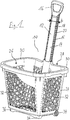
- FIG. 1 shows a perspective view of an inventive container 10 in the embodiment as a shopping basket 10 with a pull handle 12 in the pulled-out state.
- the shopping basket 10 is designed as an injection molded part, wherein the shopping basket 10 is made of unreinforced polypropylene.
- the shopping basket 10 is stackable.
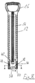
- the pull handle 12 has a guide rail 14 and a handle 16.
- the pull handle 12 is made in one piece.
- the pull handle 12 is made of glass fiber reinforced PA6 and as an injection molded part.
- Materialaus traditions 15 are provided on both narrow sides of the guide rail 14 . These material recesses 15 serve to avoid accumulation of material and to simplify the production by injection molding.
- handle 16 and the guide rail 14 are separate components, which are designed, for example, nestable.
- the handle 16 is made in one piece.
- the guide rail 14 can also be made in one piece.
- the cross section of the guide rail 14 is designed such that it has a broad side 18 (end face 18) with a width b (see FIG. 1 ) and a narrow side 20 having a depth t (see FIG. 3 and FIG. 4 ).
- the broad side 18 or end face 18 may be e.g. be printed.
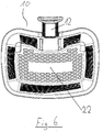
- the shopping basket 10 itself has a bottom 22 (see FIG. 6 ) and a subsequent to the bottom 22 circumferential side wall 24.
- the bottom 22 and the side wall 24 include an interior region 26 of the shopping basket 10 a.
- the inner region 26 itself is accessible via an opening 28 which is bounded on the opposite side of the bottom 22 by the edge 30 of the side wall 24.
- the side wall 24 and also the bottom 22 are provided with grid structures 32. In principle, however, it is also conceivable that the side wall 24 and / or the bottom 22 are closed.
- rollers 34 are attached to a longitudinal side of the bottom.
- support ribs 36 are provided on the opposite longitudinal side of the bottom 22.
- the shopping basket 10 stands on the rollers 34 and the support ribs 36, while it is rollable in the driving condition on the rollers 34.
- a guide tunnel 37 for guiding and at least partially receiving the guide rail 14 of the pull handle 12 is provided.
- all components of the shopping basket 10 are made of plastic, with the exception of the axis (not shown in detail) for the rollers 34 of the shopping basket 10.
- This axis can be made for example of steel.
- the guide tunnel 37 is disposed on the outside of the back of the side wall 24 and is located there in the upper third or quarter of the back of the side wall 24.
- the length of the guide tunnel 37 is about one fifth to about a quarter of the height of the side wall 24th
- the cross section of the guide tunnel 37 is in FIG. 11b can be seen (section cut CC see FIG. 11a ).
- the cross section of the guide tunnel 37 has a slightly curved or convex shape.
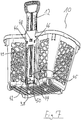
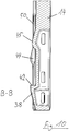
- the guide rail 14 has at its in the assembled state the bottom 22 facing the end (or at its end remote from the handle 16) a wedge-shaped locking element 38 (see, eg FIG. 5 and FIG. 7 ) that rises obliquely from the broad side 18 of the guide rail 14, in such a way that the highest elevation of the locking element 38 faces the handle 16 and there forms a locking projection 42.
- the inclined surface of the locking element 38 runs in the surface of the guide rail.
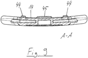
- the latching elements 44 are sprung latching elements 44, which are each arranged centrally on a spring bar 50.
- the guide tunnel 37 as a counterpart or as a stop for the locking element 38 has a formation 49, on which the locking element 38 can be stopped.
- the function of the latching element 38 can be described as follows: When inserting the pull handle 12, the locking element 38 presses the outer wall of the guide tunnel 37 to the outside, so that the guide rail 14 and the locking element 38 having a larger cross section than the opening cross section of the guide tunnel 37 can pass through the guide tunnel 37.
- the guide rail 14 is pulled by pulling the pull handle 12 from the guide tunnel 37 against the guide tunnel 37, so the locking element abuts against the projection 49 of the guide tunnel 37 and prevents complete pulling out of the pull handle 12th
- the latching element 38 is provided in the contact region with a surface which is parallel to the shaping 49 and which is wedge-shaped. Thereby, an additional clamping effect can be achieved, so that the pulling forces can be increased on the pull handle 12, so that the pull handle 12 and guide tunnel 37 can be clamped together even better.
- the curved or convex shape of the cross section of the guide tunnel 37 causes the wall of the guide tunnel 37 with the recesses 46, 48, also called the rear wall of the guide tunnel 37, as a leaf spring acts. This is particularly advantageous for the realization of the latching and snap system of the shopping basket 10.
- the shopping basket 10 can not only be pulled, but also pushed.
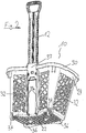
- FIGS. 2 to 11 Further views of the shopping basket 10 are as described above.
- the sectional view according to FIG. 4 as well as the representation of the sections AA and BB (cut see FIG. 8 ) in the Figures 9 and 10 shows in detail how the locking element 38 and the latching elements 44, 45 are constructed.
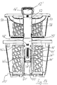
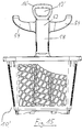
- FIGS. 12 to 16 shows a further embodiment of a shopping basket 10 'according to the invention, which has all the structural and functional features of the shopping basket 10 and its advantages.
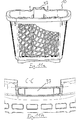
- the shopping basket 10 has a threaded on the pull handle 12' essay 52, such as from the FIGS. 15 and 16 seen, two support arms 54, on which an additional basket 56 can be held.
- the attachment 52 is guided with an attachment guide tunnel 58 on the guide rail 14 'of the pull handle 12'.
- FIG. 15 in the retracted state of the pull handle 12 'of the handle 16' shut down to the entrance of the tower guide tunnel 58 and sits on its edge.
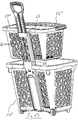
- FIGS. 17 to 21 is a further embodiment of a container according to the invention 10 "shown, which has all the structural and functional features and the associated advantages as in the Figures 1 to 11b described embodiment.
- a top rail 60 are provided for attachment to the guide rail 14 "and an additional basket 56".
- the additional basket 56 is identical to the additional basket 56, as in connection with the in the FIGS. 12 to 16 shown embodiment is visible.
- the attachment rail 60 has a central web 62, which has the width b of the guide rail 14 "substantially.
- a respective side web 64 rises.
- the central web 62 and the side webs 64 form a C-shaped profile.
- a guide wing 66 is provided in each case, which can serve for additional support of the additional basket 56 ".
- the attachment rail 60 can be clipped onto the guide rail 14 "and in the in FIG. 17 shown configuration on the extended guide rail 14 "clipped in.
- the center web 62 and the side webs 64 engage around the guide rail 14".
- guide pins 70 are provided, wherein on each guide wing 66 in the side facing away from the attachment pin 68 part of the guide wing 66 each have a guide pin 70 is provided. These guide pins 70 pass through the grid structures of the additional basket 56 "and thereby stabilize the additional basket 56" suspended on the attachment pin 68.
- the lower edge of the top rail 60 sits directly on the upper edge of the guide tunnel 37 "(see. FIG. 20 ), so that over this the weight of the additional basket 56 "can be introduced into the shopping basket 10".
Landscapes
- Engineering & Computer Science (AREA)
- Chemical & Material Sciences (AREA)
- Combustion & Propulsion (AREA)
- Transportation (AREA)
- Mechanical Engineering (AREA)
- Details Of Rigid Or Semi-Rigid Containers (AREA)
- Handcart (AREA)
Claims (15)
- Conteneur (10; 10'; 10"), en particulier panier d'achat (10; 10'; 10"), avec un fond (22) et une paroi latérale périphérique (24) se raccordant au fond (22), dans lequel le fond (22) et la paroi latérale (24) délimitent une région intérieure (26) du conteneur (10; 10'; 10"), dans lequel le conteneur (10; 10'; 10") est réalisé sous forme roulante, dans lequel le conteneur (10; 10'; 10") présente en outre un manche de traction (12; 12') avec un rail de guidage (14; 14'; 14") et une poignée (16; 16') et dans lequel il est prévu dans une région de la paroi latérale (24) un tunnel de guidage (37; 37'; 37") pour le guidage et le logement au moins partiel du rail de guidage (14; 14'; 14") du manche de traction (12; 12'), et dans lequel le rail de guidage (14; 14'; 14") présente au moins un élément d'encliquetage (38, 38'), qui est en saillie sur une face extérieure du rail de guidage (14; 14', 14"), est disposé sur une face large (18) et empêche, dans l'état monté du manche de traction (12; 12'), une extraction totale du rail de guidage (14; 14'; 14") hors du tunnel de guidage (37; 37'; 37"), caractérisé en ce que le tunnel de guidage (37; 37'; 37") présente une section transversale de forme cintrée ou convexe, en ce qu'il est en outre prévu sur le rail de guidage (14; 14'; 14") au moins un élément d'encliquetage (44, 45; 44', 45'), au moyen duquel le manche de traction (12; 12') peut, dans l'état monté du panier d'achat (10; 10'; 10"), être encliqueté dans une position étendue, et en ce que le tunnel de guidage (37; 37'; 37") présente au moins un évidement (46, 48; 46', 48'), dans lequel l'élément d'encliquetage (44, 45; 44', 45') peut être verrouillé.
- Conteneur (10; 10'; 10") selon la revendication 1, caractérisé en ce que le rail de guidage (14; 14'; 14") est réalisé en une seule pièce.
- Conteneur (10; 10'; 10") selon la revendication 1 ou la revendication 2, caractérisé en ce que le manche de traction (12; 12') est réalisé en une seule pièce.
- Conteneur (10; 10'; 10") selon la revendication 1 ou la revendication 2, caractérisé en ce que le manche de traction (12; 12') et le rail de guidage (14; 14'; 14") sont respectivement des composants séparés.
- Conteneur (10; 10'; 10") selon l'une quelconque des revendications précédentes, caractérisé en ce que le conteneur (10; 10'; 10") est réalisé en polypropylène (PP), en particulier en polypropylène non renforcé (PP).
- Conteneur (10; 10'; 10") selon l'une quelconque des revendications précédentes, caractérisé en ce que le conteneur (10; 10'; 10") est réalisé sous la forme d'une pièce moulée par injection.
- Conteneur (10; 10'; 10") selon l'une quelconque des revendications précédentes, caractérisé en ce que la poignée (16; 16') ou le manche de traction (12; 12') se compose de matière plastique renforcée par des fibres.
- Conteneur (10; 10'; 10") selon l'une quelconque des revendications précédentes, caractérisé en ce que l'élément d'encliquetage (38; 38') est formé d'une seule pièce.
- Conteneur (10; 10'; 10") selon l'une quelconque des revendications précédentes, caractérisé en ce que l'élément d'encliquetage (38; 38') est réalisé en forme de coin.
- Conteneur (10; 10'; 10") selon l'une quelconque des revendications précédentes, caractérisé en ce que le rail de guidage (14; 14'; 14") présente deux faces larges (18) avec une largeur (b), qui est au moins deux fois plus grande que la profondeur du rail de guidage (14; 14'; 14").
- Conteneur (10; 10'; 10") selon la revendication 10, caractérisé en ce que ledit au moins un élément d'encliquetage (44; 44') est monté sur ressort, en particulier est disposé sur une nervure à ressort (50; 50').
- Conteneur (10; 10'; 10") selon la revendication 11, caractérisé en ce qu'il est prévu au moins un autre élément d'encliquetage (45; 45'), qui est monté sans ressort sur le rail de guidage (14; 14'; 14").
- Conteneur (10; 10'; 10") selon l'une quelconque des revendications précédentes, caractérisé en ce que le tunnel de guidage (37; 37'; 37") présente au moins une déformation (49; 49'), dans laquelle l'élément d'encliquetage (38; 38') peut buter.
- Conteneur (10') selon l'une quelconque des revendications précédentes, caractérisé en ce qu'il est en outre prévu un support (52) pouvant être enfilé sur le manche de traction (12'), au moyen duquel un panier d'appoint (56) peut être maintenu.
- Conteneur (10") selon l'une quelconque des revendications 1 à 13, caractérisé en ce qu'il est en outre prévu un rail de support (60) pouvant être accroché au rail de guidage (14"), au moyen duquel un panier d'appoint (56") peut être maintenu.
Applications Claiming Priority (2)
| Application Number | Priority Date | Filing Date | Title |
|---|---|---|---|
| DE102015110433.4A DE102015110433B4 (de) | 2015-06-29 | 2015-06-29 | Behältnis |
| PCT/EP2016/055123 WO2017001063A1 (fr) | 2015-06-29 | 2016-03-10 | Contenant |
Publications (2)
| Publication Number | Publication Date |
|---|---|
| EP3206934A1 EP3206934A1 (fr) | 2017-08-23 |
| EP3206934B1 true EP3206934B1 (fr) | 2019-06-12 |
Family
ID=55538202
Family Applications (1)
| Application Number | Title | Priority Date | Filing Date |
|---|---|---|---|
| EP16710131.0A Active EP3206934B1 (fr) | 2015-06-29 | 2016-03-10 | Conteneur |
Country Status (7)
| Country | Link |
|---|---|
| US (1) | US10266190B2 (fr) |
| EP (1) | EP3206934B1 (fr) |
| CN (1) | CN107428353B (fr) |
| DE (1) | DE102015110433B4 (fr) |
| ES (1) | ES2738410T3 (fr) |
| PT (1) | PT3206934T (fr) |
| WO (1) | WO2017001063A1 (fr) |
Families Citing this family (4)
| Publication number | Priority date | Publication date | Assignee | Title |
|---|---|---|---|---|
| WO2018127840A1 (fr) * | 2017-01-06 | 2018-07-12 | Joalpe Industria De Expositores S.A. | Contenant monobloc segmenté à roues |
| CN112722019B (zh) * | 2018-12-27 | 2022-10-25 | 潘燕瑜 | 一种道桥工程中建筑材料的搬运装置 |
| DE102019113421A1 (de) * | 2019-05-21 | 2020-11-26 | Wanzl GmbH & Co. KGaA | Transportwagen |
| DE102021006250B4 (de) | 2021-01-04 | 2023-03-30 | Herbert Eberlein | Stapelbarer Rollkorb zum Einkaufen von Ware |
Family Cites Families (15)
| Publication number | Priority date | Publication date | Assignee | Title |
|---|---|---|---|---|
| US2352776A (en) | 1940-02-03 | 1944-07-04 | Borg Warner | Constant velocity universal joint |
| US2906212A (en) | 1955-05-19 | 1959-09-29 | American Zinc Lead & Smelting | Runway forming and load receiving multiple car assembly |
| ES2270676B1 (es) | 2004-11-18 | 2008-04-16 | Araven, S.A. | Cesta apilable mejorada. |
| US7955380B2 (en) | 2006-03-17 | 2011-06-07 | Medtronic Vascular, Inc. | Prosthesis fixation apparatus and methods |
| FR2906212B1 (fr) | 2006-09-27 | 2009-09-25 | Joalpe Ind De Expositores Sa | Panier, notamment destine pour le stockage et le transport de marchandises dans des magasins et autres surfaces de vente |
| SE531822C2 (sv) | 2007-06-13 | 2009-08-18 | Superbasket As | Anordning vid kundvagn |
| GB2450170A (en) * | 2007-06-14 | 2008-12-17 | John Kerr | Shopping trolley with inserts |
| PT104095B (pt) * | 2008-06-09 | 2010-04-19 | Joalpe Ind De Expositores Sa | Cesto com rodas para armazenamento e transporte de produtos |
| ES2352776B1 (es) | 2009-03-23 | 2012-01-09 | Araven, S.L. | Cesta para la compra con asa de tracción extraíble. |
| SE534538C2 (sv) * | 2010-03-08 | 2011-09-27 | Superbasket As | Staplingsbar varukorg med draghandtag |
| US8439374B1 (en) * | 2010-05-14 | 2013-05-14 | Richard Elden | Lightweight high load capacity folding utility cart with unique support structure and ergonomic handle |
| US20120160886A1 (en) * | 2010-12-28 | 2012-06-28 | Paul Henny | Market Basket System |
| US8567809B2 (en) * | 2011-04-13 | 2013-10-29 | Cargo Cart Co. | Collapsible shopping cart |
| PT106442A (pt) * | 2012-07-13 | 2014-01-13 | Handgo Unipessoal Lda | Cesto com rodas aperfeiçoado |
| ES1078615Y (es) | 2013-01-29 | 2013-11-20 | Ind Tomas Morcillo S L | Cesta de compra |
-
2015
- 2015-06-29 DE DE102015110433.4A patent/DE102015110433B4/de active Active
-
2016
- 2016-03-10 WO PCT/EP2016/055123 patent/WO2017001063A1/fr not_active Ceased
- 2016-03-10 US US15/550,163 patent/US10266190B2/en active Active
- 2016-03-10 PT PT16710131T patent/PT3206934T/pt unknown
- 2016-03-10 ES ES16710131T patent/ES2738410T3/es active Active
- 2016-03-10 CN CN201680011449.5A patent/CN107428353B/zh active Active
- 2016-03-10 EP EP16710131.0A patent/EP3206934B1/fr active Active
Non-Patent Citations (1)
| Title |
|---|
| None * |
Also Published As
| Publication number | Publication date |
|---|---|
| US20180043915A1 (en) | 2018-02-15 |
| US10266190B2 (en) | 2019-04-23 |
| CN107428353B (zh) | 2020-11-06 |
| CN107428353A (zh) | 2017-12-01 |
| ES2738410T3 (es) | 2020-01-22 |
| DE102015110433A1 (de) | 2016-12-29 |
| PT3206934T (pt) | 2019-09-26 |
| EP3206934A1 (fr) | 2017-08-23 |
| WO2017001063A1 (fr) | 2017-01-05 |
| DE102015110433B4 (de) | 2019-08-01 |
Similar Documents
| Publication | Publication Date | Title |
|---|---|---|
| EP3708460B1 (fr) | Chariot de transport avec porte-bebe | |
| DE102016102739A1 (de) | Transportwagen | |
| DE102015110433B4 (de) | Behältnis | |
| EP1894469B1 (fr) | Piège pour animaux | |
| EP3490872B1 (fr) | Dispositif de poignée | |
| EP3213975B1 (fr) | Plancher en plastique | |
| DE29906754U1 (de) | Rahmen zur Bildung einer stapelbaren Lager- und Transportvorrichtung für langgestreckte Gegenstände | |
| DE10127120B4 (de) | Kunststoffpalette und Palettensystem | |
| DE102008009687B4 (de) | Stoßleiste | |
| DE202015105816U1 (de) | Transportwagen | |
| EP1714889A2 (fr) | Dispositif de transport pour pièces individuelles | |
| DE2727310A1 (de) | Einkaufswagen mit kunststoffkorb | |
| DE10117546B4 (de) | Zusammenklappbarer Trockenständer | |
| EP3131834A1 (fr) | Bac à ordures avec corps en matière plastique moulé par injection | |
| DE102005017756B4 (de) | Tasche | |
| DE8234160U1 (de) | Einkaufswagen | |
| DE202014105384U1 (de) | Tragegriff für Kanister | |
| DE10200567A1 (de) | Gepäckstück mit einer Transportvorrichtung | |
| DE202015009019U1 (de) | Transportwagen | |
| DE202017101538U1 (de) | Lastenträger, insbesondere Fahrradträger | |
| DE102017101472A1 (de) | Stapelbarer Einkaufswagen | |
| DE20302679U1 (de) | Aus Kunststoff bestehendes Stangenverschlußsystem | |
| DE7934638U1 (de) | Einkaufswagen | |
| DE29710884U1 (de) | Hindernisstange für den Reitsport | |
| DE7635224U1 (de) | Einkaufswagen mit kunststoffkorb |
Legal Events
| Date | Code | Title | Description |
|---|---|---|---|
| STAA | Information on the status of an ep patent application or granted ep patent |
Free format text: STATUS: THE INTERNATIONAL PUBLICATION HAS BEEN MADE |
|
| PUAI | Public reference made under article 153(3) epc to a published international application that has entered the european phase |
Free format text: ORIGINAL CODE: 0009012 |
|
| STAA | Information on the status of an ep patent application or granted ep patent |
Free format text: STATUS: REQUEST FOR EXAMINATION WAS MADE |
|
| 17P | Request for examination filed |
Effective date: 20170518 |
|
| AK | Designated contracting states |
Kind code of ref document: A1 Designated state(s): AL AT BE BG CH CY CZ DE DK EE ES FI FR GB GR HR HU IE IS IT LI LT LU LV MC MK MT NL NO PL PT RO RS SE SI SK SM TR |
|
| AX | Request for extension of the european patent |
Extension state: BA ME |
|
| STAA | Information on the status of an ep patent application or granted ep patent |
Free format text: STATUS: EXAMINATION IS IN PROGRESS |
|
| 17Q | First examination report despatched |
Effective date: 20180509 |
|
| DAV | Request for validation of the european patent (deleted) | ||
| DAX | Request for extension of the european patent (deleted) | ||
| GRAP | Despatch of communication of intention to grant a patent |
Free format text: ORIGINAL CODE: EPIDOSNIGR1 |
|
| STAA | Information on the status of an ep patent application or granted ep patent |
Free format text: STATUS: GRANT OF PATENT IS INTENDED |
|
| INTG | Intention to grant announced |
Effective date: 20190117 |
|
| GRAS | Grant fee paid |
Free format text: ORIGINAL CODE: EPIDOSNIGR3 |
|
| GRAA | (expected) grant |
Free format text: ORIGINAL CODE: 0009210 |
|
| STAA | Information on the status of an ep patent application or granted ep patent |
Free format text: STATUS: THE PATENT HAS BEEN GRANTED |
|
| AK | Designated contracting states |
Kind code of ref document: B1 Designated state(s): AL AT BE BG CH CY CZ DE DK EE ES FI FR GB GR HR HU IE IS IT LI LT LU LV MC MK MT NL NO PL PT RO RS SE SI SK SM TR |
|
| REG | Reference to a national code |
Ref country code: GB Ref legal event code: FG4D Free format text: NOT ENGLISH |
|
| REG | Reference to a national code |
Ref country code: CH Ref legal event code: EP |
|
| REG | Reference to a national code |
Ref country code: AT Ref legal event code: REF Ref document number: 1142169 Country of ref document: AT Kind code of ref document: T Effective date: 20190615 |
|
| REG | Reference to a national code |
Ref country code: DE Ref legal event code: R096 Ref document number: 502016005023 Country of ref document: DE |
|
| REG | Reference to a national code |
Ref country code: IE Ref legal event code: FG4D Free format text: LANGUAGE OF EP DOCUMENT: GERMAN |
|
| REG | Reference to a national code |
Ref country code: PT Ref legal event code: SC4A Ref document number: 3206934 Country of ref document: PT Date of ref document: 20190926 Kind code of ref document: T Free format text: AVAILABILITY OF NATIONAL TRANSLATION Effective date: 20190909 |
|
| REG | Reference to a national code |
Ref country code: NL Ref legal event code: MP Effective date: 20190612 |
|
| REG | Reference to a national code |
Ref country code: LT Ref legal event code: MG4D |
|
| PG25 | Lapsed in a contracting state [announced via postgrant information from national office to epo] |
Ref country code: NO Free format text: LAPSE BECAUSE OF FAILURE TO SUBMIT A TRANSLATION OF THE DESCRIPTION OR TO PAY THE FEE WITHIN THE PRESCRIBED TIME-LIMIT Effective date: 20190912 Ref country code: HR Free format text: LAPSE BECAUSE OF FAILURE TO SUBMIT A TRANSLATION OF THE DESCRIPTION OR TO PAY THE FEE WITHIN THE PRESCRIBED TIME-LIMIT Effective date: 20190612 Ref country code: SE Free format text: LAPSE BECAUSE OF FAILURE TO SUBMIT A TRANSLATION OF THE DESCRIPTION OR TO PAY THE FEE WITHIN THE PRESCRIBED TIME-LIMIT Effective date: 20190612 Ref country code: FI Free format text: LAPSE BECAUSE OF FAILURE TO SUBMIT A TRANSLATION OF THE DESCRIPTION OR TO PAY THE FEE WITHIN THE PRESCRIBED TIME-LIMIT Effective date: 20190612 Ref country code: AL Free format text: LAPSE BECAUSE OF FAILURE TO SUBMIT A TRANSLATION OF THE DESCRIPTION OR TO PAY THE FEE WITHIN THE PRESCRIBED TIME-LIMIT Effective date: 20190612 Ref country code: LT Free format text: LAPSE BECAUSE OF FAILURE TO SUBMIT A TRANSLATION OF THE DESCRIPTION OR TO PAY THE FEE WITHIN THE PRESCRIBED TIME-LIMIT Effective date: 20190612 |
|
| PG25 | Lapsed in a contracting state [announced via postgrant information from national office to epo] |
Ref country code: BG Free format text: LAPSE BECAUSE OF FAILURE TO SUBMIT A TRANSLATION OF THE DESCRIPTION OR TO PAY THE FEE WITHIN THE PRESCRIBED TIME-LIMIT Effective date: 20190912 Ref country code: RS Free format text: LAPSE BECAUSE OF FAILURE TO SUBMIT A TRANSLATION OF THE DESCRIPTION OR TO PAY THE FEE WITHIN THE PRESCRIBED TIME-LIMIT Effective date: 20190612 Ref country code: GR Free format text: LAPSE BECAUSE OF FAILURE TO SUBMIT A TRANSLATION OF THE DESCRIPTION OR TO PAY THE FEE WITHIN THE PRESCRIBED TIME-LIMIT Effective date: 20190913 Ref country code: LV Free format text: LAPSE BECAUSE OF FAILURE TO SUBMIT A TRANSLATION OF THE DESCRIPTION OR TO PAY THE FEE WITHIN THE PRESCRIBED TIME-LIMIT Effective date: 20190612 |
|
| REG | Reference to a national code |
Ref country code: ES Ref legal event code: FG2A Ref document number: 2738410 Country of ref document: ES Kind code of ref document: T3 Effective date: 20200122 |
|
| REG | Reference to a national code |
Ref country code: DE Ref legal event code: R081 Ref document number: 502016005023 Country of ref document: DE Owner name: WANZL GMBH & CO. KGAA, DE Free format text: FORMER OWNER: WANZL METALLWARENFABRIK GMBH, 89340 LEIPHEIM, DE |
|
| PG25 | Lapsed in a contracting state [announced via postgrant information from national office to epo] |
Ref country code: SK Free format text: LAPSE BECAUSE OF FAILURE TO SUBMIT A TRANSLATION OF THE DESCRIPTION OR TO PAY THE FEE WITHIN THE PRESCRIBED TIME-LIMIT Effective date: 20190612 Ref country code: NL Free format text: LAPSE BECAUSE OF FAILURE TO SUBMIT A TRANSLATION OF THE DESCRIPTION OR TO PAY THE FEE WITHIN THE PRESCRIBED TIME-LIMIT Effective date: 20190612 Ref country code: RO Free format text: LAPSE BECAUSE OF FAILURE TO SUBMIT A TRANSLATION OF THE DESCRIPTION OR TO PAY THE FEE WITHIN THE PRESCRIBED TIME-LIMIT Effective date: 20190612 Ref country code: EE Free format text: LAPSE BECAUSE OF FAILURE TO SUBMIT A TRANSLATION OF THE DESCRIPTION OR TO PAY THE FEE WITHIN THE PRESCRIBED TIME-LIMIT Effective date: 20190612 |
|
| PG25 | Lapsed in a contracting state [announced via postgrant information from national office to epo] |
Ref country code: SM Free format text: LAPSE BECAUSE OF FAILURE TO SUBMIT A TRANSLATION OF THE DESCRIPTION OR TO PAY THE FEE WITHIN THE PRESCRIBED TIME-LIMIT Effective date: 20190612 Ref country code: IS Free format text: LAPSE BECAUSE OF FAILURE TO SUBMIT A TRANSLATION OF THE DESCRIPTION OR TO PAY THE FEE WITHIN THE PRESCRIBED TIME-LIMIT Effective date: 20191012 |
|
| RAP2 | Party data changed (patent owner data changed or rights of a patent transferred) |
Owner name: WANZL GMBH & CO. KGAA |
|
| REG | Reference to a national code |
Ref country code: DE Ref legal event code: R097 Ref document number: 502016005023 Country of ref document: DE |
|
| PG25 | Lapsed in a contracting state [announced via postgrant information from national office to epo] |
Ref country code: TR Free format text: LAPSE BECAUSE OF FAILURE TO SUBMIT A TRANSLATION OF THE DESCRIPTION OR TO PAY THE FEE WITHIN THE PRESCRIBED TIME-LIMIT Effective date: 20190612 |
|
| PLBE | No opposition filed within time limit |
Free format text: ORIGINAL CODE: 0009261 |
|
| STAA | Information on the status of an ep patent application or granted ep patent |
Free format text: STATUS: NO OPPOSITION FILED WITHIN TIME LIMIT |
|
| PG25 | Lapsed in a contracting state [announced via postgrant information from national office to epo] |
Ref country code: PL Free format text: LAPSE BECAUSE OF FAILURE TO SUBMIT A TRANSLATION OF THE DESCRIPTION OR TO PAY THE FEE WITHIN THE PRESCRIBED TIME-LIMIT Effective date: 20190612 Ref country code: DK Free format text: LAPSE BECAUSE OF FAILURE TO SUBMIT A TRANSLATION OF THE DESCRIPTION OR TO PAY THE FEE WITHIN THE PRESCRIBED TIME-LIMIT Effective date: 20190612 |
|
| 26N | No opposition filed |
Effective date: 20200313 |
|
| PG25 | Lapsed in a contracting state [announced via postgrant information from national office to epo] |
Ref country code: IS Free format text: LAPSE BECAUSE OF FAILURE TO SUBMIT A TRANSLATION OF THE DESCRIPTION OR TO PAY THE FEE WITHIN THE PRESCRIBED TIME-LIMIT Effective date: 20200224 Ref country code: SI Free format text: LAPSE BECAUSE OF FAILURE TO SUBMIT A TRANSLATION OF THE DESCRIPTION OR TO PAY THE FEE WITHIN THE PRESCRIBED TIME-LIMIT Effective date: 20190612 |
|
| PG2D | Information on lapse in contracting state deleted |
Ref country code: IS |
|
| REG | Reference to a national code |
Ref country code: ES Ref legal event code: PC2A Owner name: WANZL GMBH & CO. KGAA Effective date: 20200916 |
|
| PG25 | Lapsed in a contracting state [announced via postgrant information from national office to epo] |
Ref country code: MC Free format text: LAPSE BECAUSE OF FAILURE TO SUBMIT A TRANSLATION OF THE DESCRIPTION OR TO PAY THE FEE WITHIN THE PRESCRIBED TIME-LIMIT Effective date: 20190612 |
|
| REG | Reference to a national code |
Ref country code: CH Ref legal event code: PL |
|
| REG | Reference to a national code |
Ref country code: BE Ref legal event code: MM Effective date: 20200331 |
|
| PG25 | Lapsed in a contracting state [announced via postgrant information from national office to epo] |
Ref country code: LU Free format text: LAPSE BECAUSE OF NON-PAYMENT OF DUE FEES Effective date: 20200310 |
|
| PG25 | Lapsed in a contracting state [announced via postgrant information from national office to epo] |
Ref country code: IE Free format text: LAPSE BECAUSE OF NON-PAYMENT OF DUE FEES Effective date: 20200310 Ref country code: CH Free format text: LAPSE BECAUSE OF NON-PAYMENT OF DUE FEES Effective date: 20200331 Ref country code: LI Free format text: LAPSE BECAUSE OF NON-PAYMENT OF DUE FEES Effective date: 20200331 |
|
| PG25 | Lapsed in a contracting state [announced via postgrant information from national office to epo] |
Ref country code: BE Free format text: LAPSE BECAUSE OF NON-PAYMENT OF DUE FEES Effective date: 20200331 |
|
| REG | Reference to a national code |
Ref country code: AT Ref legal event code: MM01 Ref document number: 1142169 Country of ref document: AT Kind code of ref document: T Effective date: 20210310 |
|
| PG25 | Lapsed in a contracting state [announced via postgrant information from national office to epo] |
Ref country code: MT Free format text: LAPSE BECAUSE OF FAILURE TO SUBMIT A TRANSLATION OF THE DESCRIPTION OR TO PAY THE FEE WITHIN THE PRESCRIBED TIME-LIMIT Effective date: 20190612 Ref country code: CY Free format text: LAPSE BECAUSE OF FAILURE TO SUBMIT A TRANSLATION OF THE DESCRIPTION OR TO PAY THE FEE WITHIN THE PRESCRIBED TIME-LIMIT Effective date: 20190612 |
|
| PG25 | Lapsed in a contracting state [announced via postgrant information from national office to epo] |
Ref country code: MK Free format text: LAPSE BECAUSE OF FAILURE TO SUBMIT A TRANSLATION OF THE DESCRIPTION OR TO PAY THE FEE WITHIN THE PRESCRIBED TIME-LIMIT Effective date: 20190612 |
|
| PG25 | Lapsed in a contracting state [announced via postgrant information from national office to epo] |
Ref country code: AT Free format text: LAPSE BECAUSE OF NON-PAYMENT OF DUE FEES Effective date: 20210310 |
|
| P01 | Opt-out of the competence of the unified patent court (upc) registered |
Effective date: 20230523 |
|
| PGFP | Annual fee paid to national office [announced via postgrant information from national office to epo] |
Ref country code: ES Payment date: 20250416 Year of fee payment: 10 |
|
| PGFP | Annual fee paid to national office [announced via postgrant information from national office to epo] |
Ref country code: IT Payment date: 20250331 Year of fee payment: 10 |
|
| PGFP | Annual fee paid to national office [announced via postgrant information from national office to epo] |
Ref country code: GB Payment date: 20260317 Year of fee payment: 11 |
|
| PGFP | Annual fee paid to national office [announced via postgrant information from national office to epo] |
Ref country code: DE Payment date: 20260331 Year of fee payment: 11 |
|
| PGFP | Annual fee paid to national office [announced via postgrant information from national office to epo] |
Ref country code: FR Payment date: 20260324 Year of fee payment: 11 |
|
| PGFP | Annual fee paid to national office [announced via postgrant information from national office to epo] |
Ref country code: PT Payment date: 20260226 Year of fee payment: 11 Ref country code: CZ Payment date: 20260225 Year of fee payment: 11 |