EP3206981B1 - Befestigung für einen doffergreifer - Google Patents
Befestigung für einen doffergreifer Download PDFInfo
- Publication number
- EP3206981B1 EP3206981B1 EP15775511.7A EP15775511A EP3206981B1 EP 3206981 B1 EP3206981 B1 EP 3206981B1 EP 15775511 A EP15775511 A EP 15775511A EP 3206981 B1 EP3206981 B1 EP 3206981B1
- Authority
- EP
- European Patent Office
- Prior art keywords
- doffer
- gripper
- elastic retaining
- spring
- spring element
- Prior art date
- Legal status (The legal status is an assumption and is not a legal conclusion. Google has not performed a legal analysis and makes no representation as to the accuracy of the status listed.)
- Active
Links
Images


Classifications
-
- D—TEXTILES; PAPER
- D01—NATURAL OR MAN-MADE THREADS OR FIBRES; SPINNING
- D01H—SPINNING OR TWISTING
- D01H9/00—Arrangements for replacing or removing bobbins, cores, receptacles, or completed packages at paying-out or take-up stations ; Combination of spinning-winding machine
- D01H9/001—Bobbin-taking arrangements
- D01H9/003—Graspers operating under the action of a fluid
-
- B—PERFORMING OPERATIONS; TRANSPORTING
- B65—CONVEYING; PACKING; STORING; HANDLING THIN OR FILAMENTARY MATERIAL
- B65H—HANDLING THIN OR FILAMENTARY MATERIAL, e.g. SHEETS, WEBS, CABLES
- B65H67/00—Replacing or removing cores, receptacles, or completed packages at paying-out, winding, or depositing stations
- B65H67/06—Supplying cores, receptacles, or packages to, or transporting from, winding or depositing stations
- B65H67/068—Supplying or transporting empty cores
-
- B—PERFORMING OPERATIONS; TRANSPORTING
- B65—CONVEYING; PACKING; STORING; HANDLING THIN OR FILAMENTARY MATERIAL
- B65H—HANDLING THIN OR FILAMENTARY MATERIAL, e.g. SHEETS, WEBS, CABLES
- B65H2701/00—Handled material; Storage means
- B65H2701/30—Handled filamentary material
- B65H2701/31—Textiles threads or artificial strands of filaments
Definitions
- the invention relates to a doffer gripper for attachment to a doffer beam, comprising a fastening element, which comprises two spaced apart elastic retaining tabs and arranged between the elastic retaining tabs rigid support member, wherein the two elastic retaining tabs connected at a first end to the fastening element are and are positioned with a second free end in each case via at least one spring element in a rest position.
- the spinning machines have a doffer device with a doffer bar, which is arranged movably on the spinning machine, for example via a scissors mechanism.
- a plurality of doffer grippers are arranged on the doffer bar in order to be able to grasp and remove the sleeves together or put them on.
- the individual doffer grippers are preferably pneumatically actuated and include a pressurizable membrane, which is brought over the sleeves and then engages the sleeves by introducing compressed air.
- air supply ducts are arranged in the doffer bar, from which the compressed air is led via feeds to the individual membranes of the doffer gripper.
- the invention now has the object to eliminate this drawback of the known Doffergreifers.
- the at least one spring element is formed integrally with the free end of the respective elastic retaining tab and the rigid support member.
- integral means that the spring element is fixedly connected to the free end of the respective elastic retaining tab and the rigid support member.
- the at least one spring element is made of an elastic plastic. This has the advantage that the elastsiche spring element is molded onto the respective elastic retaining tab and the rigid support member. The fastener, the elastic retaining tabs, the rigid support member and the spring element can thus in one operation from a single Injection molded part are produced. The production costs of the doffing gripper can be further reduced thereby.
- the at least one spring element in the direction of the free ends of the elastic retaining tabs has a width of 2-10mm.
- the respective elastic retaining tab has sufficient rigidity in its rest position and is held in this position.
- the spring element exerts a high spring force on the respective elastic retaining tab when deflected from its rest position. A sufficient clamping action of the elastic retaining tabs on the doffer bar is thus ensured.
- the at least one spring element in the rest position has a curvature or pre-bend in its longitudinal direction.
- the longitudinal direction represents the direction in which the spring element exerts a spring force on the elastic retaining tab.
- the spring element is thereby pre-bent in the rest position, that is, the spring element is in the rest position outside a vertical plane, which runs parallel to the two end faces of the elastic retaining tabs.
- each one spring element is arranged on one of the two end faces of the respective elastic retaining tab.
- each one spring element is arranged on one of the two end faces of the respective elastic retaining tab.
- the two spring elements are each integrally connected via a connecting piece with a side surface of the fastening element.
- the connector extends in the direction of the free end of the elastic retaining tabs and is integrally connected to the rigid support member and the side surface of the fastener. The connector ensures high stability of the doffer gripper.
- the side surface of the fastening element has a curvature in its longitudinal direction.
- the curvature advantageously corresponds to the curvature of the spring element in its rest position.
- the curvature on the side surface of the fastener has a positive effect on the production of Doffergreifers.
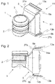
- Fig. 1 shows a doffer gripper belonging to the prior art 1.
- the doffer gripper 1 is made of plastic and has a cylindrical receptacle 2 for a coil or bobbin, not shown.
- a pneumatically adjustable clamping element 3 is arranged in the cylindrical receptacle 2. With the clamping element 3, it is possible to detect the end region of the introduced into the interior of the Doffergreifers 1 coil or bobbin tube from the outside.
- the doffer gripper 1 comprises a fastening element 5 with two elastic retaining tabs 6a, 6b arranged at a distance from one another.
- the elastic retaining tabs 6a, 6b are connected to the fastening element 5 with a first end 27a, 27b.
- the fastening element 5 between the elastic retaining tabs 6a, 6b, a rigid support member 7, in which an air duct 8 for the air supply of the pneumatically adjustable clamping member 3 and a cylindrical cavity 9 for receiving an elastic sealing element 10 are arranged ( Fig.3 and Fig.4 ).
- the doffer gripper 1 via the elastic retaining tabs 6a, 6b disengaged and releasably attachable to the doffer bar 4.
- the doffer bar 4 has on its surface an upper and a lower latching groove 11a, 11b, which extends in the longitudinal direction of the doffer bar 4.
- the two locking grooves 11a, 11b each have a profile of mutually parallel lugs 12a, 12b, in which the elastically deformable retaining tabs 6a, 6b engage with their free end 13a, 13b.
- About the two locking grooves 11 a, 11 b is a plurality of doffer grippers 1 side by side releasably and latched to the doffer bar 4 attachable.
- the holding or clamping action of the elastic retaining tabs 6a, 6b in the respective latching groove 11a, 11b is increased or supported by a replaceable steel spring 14a, 14b latched underneath the elastic retaining tab 6a, 6b.
- the steel spring 14a, 14b is designed U-shaped. With its first leg 15a, 15b, the steel spring 14a, 14b rests on the rigid support element 7. With its second leg 16a, 16b, the steel spring 14a, 14b positions the free end 13a, 13b of the elastic retaining tab 6a, 6b in a rest position (FIG. Fig.2 and Figure 3 ).
- the elastic retaining tabs 6a, 6b are compressed in the direction of the rigid support element 7, ie the elastic retaining tabs 6a, 6b are deflected out of their rest position.
- the steel spring 14a, 14b is stretched.
- the elastic retaining tabs 6a, 6b are released again, ie the force applied externally to the elastic retaining tabs 6a, 6b is removed.
- the free end 13a, 13b of the elastic retaining tab 6a, 6b by the restoring force of the steel spring 14a, 14b against the lugs 12a, 12b of the locking groove 11a, 11b pressed ( Figure 4 ).
- the stiffness or the clamping effect of the elastic retaining tabs 6a, 6b can thus be adjusted to the desired value via the steel spring 14a, 14b.
- a major disadvantage of the doffer gripper 1 described is that the doffer gripper 1 due to the additional steel spring 14a, 14b has a complex structure, whereby the production costs of the doffer gripper 1 are relatively high.
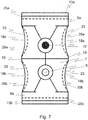
- FIG. 5 1 shows a perspective view of a doffer gripper 1 according to the invention.
- the doffer gripper 1 is like the known doffer gripper (FIG. Fig.1 ) made of plastic and has a cylindrical receptacle 2 for a coil, not shown, or bobbin tube.
- a pneumatically adjustable clamping element 3 is arranged in the cylindrical receptacle 2. With the clamping element 3, it is possible to detect the end region of the introduced into the interior of the Doffergreifers 1 coil or bobbin tube from the outside.
- the doffer gripper 1 For fastening the doffer gripper 1 to a doffer bar 4, the doffer gripper 1, like the known doffer gripper, comprises a fastening element 5 with two elastic retaining tabs 6a, 6b arranged at a distance from one another.
- the elastic retaining tabs 6a, 6b are connected to the fastening element 5 with a first end 27a, 27b.
- a rigid support element 7 is arranged on the fastening element 5, in which an air duct 8 for the air supply of the pneumatically adjustable clamping element 3 and a cylindrical cavity 9 for receiving an elastic sealing element 10 are arranged ( Figure 7 ).
- the doffer gripper 1 is like the well-known doffer gripper ( Figure 4 ) via the elastic retaining tabs 6 a, 6 b disengaged and releasably attachable to the doffer bar 4.
- the doffer gripper 1 in contrast to the known doffer gripper on no additional steel springs.
- a spring element 18a, 18b made of plastic is arranged in the embodiment of the doffer gripper 1 according to the invention at the two end faces 17a, 17b of the elastic retaining tabs 6a, 6b.
- the doffer gripper 1 thus has four spring elements ( Figure 7 ).
- the spring element 18a, 18b is integrally connected to the free end 13a, 13b of the elastic retaining tab 6a, 6b and a connecting piece 19.
- the connecting piece 19 is part of the rigid support element 7 and extends in the direction of the free end 13a, 13b of the elastic retaining tabs 6a, 6b.
- the connecting piece 19 is integrally connected to a side surface 20 of the fastening element 5.
- the spring elements 18a, 18b are thus firmly integrated into the fastening element 5 and position the free end 13a, 13b of the elastic retaining tab 6a, 6b in a rest position.
- the spring element 18a, 18b has a width 21 of 5 mm in the direction of the free end 13a, 13b of the elastic retaining tabs 6a, 6b.
- a free gap 22 remains between the spring element 18a, 18b and the side surface 20 of the fastening element 5.
- the spring element 18a, 18b has in its rest position in its longitudinal direction a curvature 23 or pre-bend (FIG. Figure 7 ).
- the side surface 20 of the fastener 5 has a curvature 24 which is formed to match the curvature 23 of the spring element 18a, 18b.
- the elastic holding straps 6a, 6b are compressed in the direction of the rigid support element 7, ie the elastic holding straps 6a, 6b are deflected out of their rest position (dashed line 25a, 25b in FIG Figure 7 ).
- the spring elements 18a, 18b according to the dashed line 26a, 26b in Figure 7 further bent or stretched.
- the elastic retaining tabs 6a, 6b are released again, ie the force applied externally to the elastic retaining tabs 6a, 6b is removed again.
- the free end 13a, 13b of the elastic retaining tabs 6a, 6b pressed by the restoring force of the spring elements 18a, 18b against the lugs 12a, 12b of the locking groove 11a, 11b.
- the stiffness or the clamping action of the elastic retaining tabs 6a, 6b can thus be adjusted to the desired value via the spring elements 18a, 18b made of plastic by means of a corresponding geometric design.
Landscapes
- Engineering & Computer Science (AREA)
- Mechanical Engineering (AREA)
- Textile Engineering (AREA)
- Preliminary Treatment Of Fibers (AREA)
- Clamps And Clips (AREA)
- Spinning Or Twisting Of Yarns (AREA)
- Buckles (AREA)
Description
- Die Erfindung bezieht sich auf einen Doffergreifer zur Befestigung an einem Dofferbalken, mit einem Befestigungselement, welches zwei in einem Abstand zueinander angeordnete elastische Haltelaschen und ein zwischen den elastischen Haltelaschen angeordnetes starres Stützelement umfasst, wobei die zwei elastischen Haltelaschen mit einem ersten Ende mit dem Befestigungselement verbunden sind und mit einem zweiten freien Ende jeweils über wenigstens ein Federelement in einer Ruhelage positioniert sind.
- Bei einer Vielzahl von Spinnmaschinen, insbesondere bei Ringspinnmaschinen, werden bei einem Spulenwechselvorgang eine Vielzahl bereits fertig bewickelter Hülsen bzw. Kopse gemeinsam an den Spinnstellen der Spinnmaschine abgenommen und durch leere Spulenhülsen ersetzt. Die Spinnmaschinen weisen hierzu eine Doffervorrichtung mit einem Dofferbalken auf, welcher beispielsweise über einen Scherenmechanismus beweglich an der Spinnmaschine angeordnet ist. An dem Dofferbalken ist wiederum eine Vielzahl von Doffergreifern angeordnet, um die Hülsen gemeinsam greifen und abnehmen bzw. aufstecken zu können. Die einzelnen Doffergreifer sind bevorzugt pneumatisch betätigbar und beinhalten eine druckluftbeaufschlagbare Membran, welche über die Hülsen gebracht wird und anschliessend die Hülsen durch Einbringen von Druckluft greift. Zum Beaufschlagen der einzelnen Doffergreifer mit Druckluft sind druckluftzuführende Kanäle im Dofferbalken angeordnet, von welchem die Druckluft über Zuführungen jeweils zu den einzelnen Membranen der Doffergreifer geleitet wird.
- Die
EP 0 303 877 A1 beschreibt eine derartige Doffervorrichtung mit einem entsprechend ausgebildeten Doffergreifer. Der Doffergreifer umfasst dabei zur Befestigung an dem Dofferbalken ein Befestigungselement, das zwei in einem Abstand zueinander angeordnete elastische Haltelaschen aufweist. Das Befestigungselement weist ferner zwischen den elastischen Haltelaschen ein starres Stützelement auf. Über die elastischen Haltelaschen ist der Doffergreifer ausrastbar und lösbar an dem Dofferbalken befestigt. Der Dofferbalken ist hierzu an seiner Oberfläche mit einer oberen und einer unteren Rastnut versehen, die sich in Längsrichtung des Dofferbalkens erstreckt. Die Rastnut weist ein Profil aus parallel zueinander verlaufenden Nasen auf, in welches die elastisch verformbaren Haltelaschen mit ihren freien Enden einrasten. Die beiden Rastnuten ermöglichen, eine Mehrzahl von individuellen Doffergreifern entlang dem Dofferbalken zu befestigen. Die Halte- bzw. Klemmwirkung der Haltelaschen wird von einer unterhalb der Haltelaschen eingeschnappten, austauschbaren Stahlfeder erhöht bzw. unterstützt. Die Stahlfeder liegt dabei mit ihrem einen Ende auf dem starren Stützelement auf und belastet mit ihrem anderen Ende das freie Ende der Haltelasche. Die Straffheit der Haltelaschen kann somit über die Stahlfeder auf den gewünschten Wert eingestellt werden. Ein wesentlicher Nachteil des beschriebenen Doffergreifers besteht darin, dass der Doffergreifer aufgrund seines Aufbaus hohe Herstellkosten aufweist. - Die Erfindung stellt sich nunmehr die Aufgabe diesen Nachteil des bekannten Doffergreifers zu beseitigen.
- Die Aufgabe wird erfindungsgemäss dadurch gelöst, dass das wenigstens eine Federelement mit dem freien Ende der jeweiligen elastischen Haltelasche und dem starren Stützelement einstückig ausgebildet ist. Der Begriff "einstückig" bedeutet, dass das Federelement mit dem freien Ende der jeweiligen elastischen Haltelasche und dem starren Stützelement fest verbunden ist. Dies stellt einen wesentlichen Unterschied zum Doffergreifer des Standes der Technik dar, bei welchem das Federelement lösbar mit dem freien Ende der jeweiligen elastischen Haltelasche und dem starren Stützelement verbunden ist. Durch die einstückige Verbindung des Federelements mit dem freien Ende der jeweiligen elastischen Haltelasche und dem starren Stützelement wird der Aufbau des Doffergreifers stark vereinfacht, da im Unterschied zum Stand der Technik die Verwendung einer zusätzlichen Stahlfeder zur Erzeugung der Klemmkraft am Dofferbalken entfällt. Als Folge ist der Doffergreifer kostengünstig herstellbar.
- Weiter hat es sich als vorteilhaft erwiesen, wenn das wenigstens eine Federelement aus einem elastischen Kunststoff ist. Dies hat den Vorteil, dass das elastsiche Federelement an die jeweilige elastische Haltelasche und das starre Stützelement angespritzt ist. Das Befestigungselement, die elastischen Haltelaschen, das starre Stützelement und das Federelement können somit in einem Arbeitsgang aus einem einzigen Spritzgussteil hergestellt werden. Die Herstellkosten des Doffergreifers können hierdurch weiter gesenkt werden.
- Um eine ausreichende Federwirkung zu erzielen, ist es auch von Vorteil, wenn das wenigstens eine Federelement in Richtung der freien Enden der elastischen Haltelaschen eine Breite von 2-10mm aufweist. Über diese Breite des Federelements wird erreicht, dass die jeweilige elastische Haltelasche in ihrer Ruhelage eine ausreichende Steifigkeit aufweist und in dieser Lage gehalten wird. Zudem wird sichergestellt, dass das Federelement bei Auslenkung aus seiner Ruhelage eine hohe Federkraft auf die jeweilige elastische Haltelasche ausübt. Eine ausreichende Klemmwirkung der elastischen Haltelaschen am Dofferbalken ist somit sichergestellt.
- Zudem ist es vorteilhaft, wenn das wenigstens eine Federelement in der Ruhelage in seiner Längsrichtung eine Wölbung bzw. Vorbiegung aufweist. Die Längsrichtung stellt dabei die Richtung dar, in welcher das Federelement eine Federkraft auf die elastische Haltelasche ausübt. Das Federelement ist dadurch in der Ruhelage vorgebogen, d.h das Federelement liegt in der Ruhelage ausserhalb einer vertikalen Ebene, welche parallel zu den beiden Stirnseiten der elastischen Haltelaschen verläuft. Mittels der Vorbiegung wird erreicht, dass das Federelement auch bei einer geringen Auslenkung der elastischen Haltelasche aus ihrer Ruhelage eine hohe Federkraft auf die elastische Haltelasche ausübt. Hierdurch ist auch bei hohen Fertigungstoleranzen der Rastnut des Dofferbalkens eine ausreichende Klemmwirkung der elastischen Haltelaschen in der Rastnut sichergestellt.
- Weiter ist es vorteilhaft, wenn zwei Federelemente mit dem freien Ende der jeweiligen elastischen Haltelasche und dem starren Stützelement einstückig verbunden sind, wobei je ein Federelement an einer der beiden Stirnseiten der jeweiligen elastischen Haltelasche angeordnet ist. Hierdurch wird erreicht, dass die jeweilige elastische Haltelasche bei ihrer Auslenkung mit einer hohen Federkraft beaufschlagt wird. Zudem wird mittels der beiden Federelemente erreicht, dass die jeweilige elastische Haltelasche bei Auslenkung aus ihrer Ruhelage über ihre Breite gesehen gleichmässig mit einer Federkraft beaufschlagt wird. Somit ist auch bei hohen Fertigungstoleranzen der Rastnut des Dofferbalkens eine ausreichende Klemmwirkung der elastischen Haltelaschen in der Rastnut sichergestellt.
- Vorteilhaft ist es auch, wenn die zwei Federelemente jeweils über ein Verbindungsstück mit einer Seitenfläche des Befestigungselements einstückig verbunden sind. Das Verbindungsstück verläuft dabei in Richtung des freien Endes der elastischen Haltelaschen und ist einstückig mit dem starren Stützelement und der Seitenfläche des Befestigungselements verbunden. Über das Verbindungsstück wird eine hohe Stabilität des Doffergreifers sichergestellt.
- Schliesslich ist es von Vorteil, wenn die Seitenfläche des Befestigungselements in ihrer Längsrichtung eine Wölbung aufweist. Die Wölbung entspricht dabei vorteilhafterweise der Wölbung des Federelements in seiner Ruhelage. Die Wölbung an der Seitenfläche des Befestigungselements wirkt sich positiv auf die Fertigung des Doffergreifers aus.
- Weitere Merkmale der Erfindung ergeben sich aus der nachfolgenden Beschreibung einer in den Figuren dargestellten Ausführungsform. Es zeigen:
- Fig.1
- eine perspektivische Darstellung eines zum Stand der Technik gehörenden Doffergreifers,
- Fig.2
- eine Seitenansicht X1 des Doffergreifers aus
Fig.1 , - Fig.3
- eine Rückansicht Y1 des Doffergreifers aus
Fig.1 , - Fig.4
- einen Teilquerschnitt eines an einem Dofferbalken befestigten Doffergreifers aus
Fig.1 , - Fig.5
- eine perspektivische Darstellung eines erfindungsgemässen Doffergreifers,
- Fig.6
- eine Seitenansicht X5 des Doffergreifers aus
Fig.5 und - Fig.7
- eine Rückansicht Y5 des Doffergreifers aus
Fig.5 . -
Fig. 1 zeigt einen zum Stand der Technik gehörenden Doffergreifer 1. Der Doffergreifer 1 ist aus Kunststoff hergestellt und besitzt eine zylindrische Aufnahme 2 für eine nicht dargestellte Spule oder Spulenhülse. In der zylindrischen Aufnahme 2 ist ein pneumatisch verstellbares Klemmelement 3 angeordnet. Mit dem Klemmelement 3 ist es möglich, den Endbereich der in das Innere des Doffergreifers 1 eingeführten Spule oder Spulenhülse von aussen zu erfassen. Zur Befestigung des Doffergreifers 1 an einem in Maschinenlängsrichtung verlaufenden Dofferbalken 4 (Fig.4 ), umfasst der Doffergreifer 1 ein Befestigungselement 5 mit zwei in einem Abstand zueinander angeordneten elastischen Haltelaschen 6a,6b. Die elastischen Haltelaschen 6a,6b sind mit einem ersten Ende 27a,27b mit dem Befestigungselement 5 verbunden. Zudem umfasst das Befestigungselement 5 zwischen den elastischen Haltelaschen 6a,6b ein starres Stützelement 7, in welchem ein Luftkanal 8 für die Luftzufuhr des pneumatisch verstellbaren Klemmelements 3 und ein zylinderförmiger Hohlraum 9 zur Aufnahme eines elastischen Abdichtungselements 10 angeordnet sind (Fig.3 und Fig.4 ). Wie inFig. 4 dargestellt, ist der Doffergreifer 1 über die elastischen Haltelaschen 6a,6b ausrastbar und lösbar an dem Dofferbalken 4 anbringbar. Der Dofferbalken 4 weist hierzu an seiner Oberfläche eine obere und eine unteren Rastnut 11a, 11b auf, die sich in Längsrichtung des Dofferbalkens 4 erstreckt. Die beiden Rastnuten 11a, 11b weisen jeweils ein Profil aus parallel zueinander verlaufenden Nasen 12a,12b auf, in welches die elastisch verformbaren Haltelaschen 6a,6b mit ihrem freien Ende 13a, 13b einrasten. Über die beiden Rastnuten 11a, 11b ist eine Vielzahl von Doffergreifern 1 nebeneinander lösbar und verrastbar an dem Dofferbalken 4 anbringbar. - Die Halte- bzw. Klemmwirkung der elastischen Haltelasche 6a,6b in der jeweiligen Rastnut 11a, 11b wird von einer unterhalb der elastischen Haltelasche 6a,6b eingeschnappten, austauschbaren Stahlfeder 14a,14b erhöht bzw. unterstützt. Die Stahlfeder 14a, 14b ist dabei U-förmig ausgeführt. Mit ihrem ersten Schenkel 15a,15b liegt die Stahlfeder 14a,14b auf dem starren Stützelement 7 auf. Mit ihrem zweiten Schenkel 16a, 16b positioniert die Stahlfeder 14a, 14b das freie Ende 13a, 13b der elastischen Haltelasche 6a,6b in einer Ruhelage (
Fig.2 undFig.3 ). Um den Doffergreifer 1 an den Dofferbalken 4 anzuklipsen, werden die elastischen Haltelaschen 6a,6b in Richtung des starren Stützelements 7 zusammengedrückt, d.h die elastischen Haltelaschen 6a,6b werden aus ihrer Ruhelage ausgelenkt. Dabei wird die Stahlfeder 14a,14b gespannt. In der jeweiligen Rastnut 11a, 11b werden die elastischen Haltelaschen 6a,6b wieder freigegeben, d.h die von aussen auf die elastischen Haltelaschen 6a,6b aufgebrachte Kraft wird entfernt. Hierbei wird das freie Ende 13a, 13b der elastischen Haltelasche 6a,6b durch die Rückstellkraft der Stahlfeder 14a,14b gegen die Nasen 12a,12b der Rastnut 11a, 11b gedrückt (Fig.4 ). Die Steifheit bzw. die Klemmwirkung der elastischen Haltelaschen 6a,6b kann somit über die Stahlfeder 14a,14b auf den gewünschten Wert eingestellt werden. Ein wesentlicher Nachteil des beschriebenen Doffergreifers 1 besteht darin, dass der Doffergreifer 1 aufgrund der zusätzlichen Stahlfeder 14a, 14b einen aufwändigen Aufbau aufweist, wodurch die Herstellkosten des Doffergreifers 1 relativ hoch sind. -
Figur 5 zeigt eine perspektivische Ansicht eines erfindungsgemässen Doffergreifers 1. Der Doffergreifer 1 ist wie der bekannte Doffergreifer (Fig.1 ) aus Kunststoff hergestellt und besitzt eine zylindrische Aufnahme 2 für eine nicht dargestellte Spule oder Spulenhülse. In der zylindrischen Aufnahme 2 ist ein pneumatisch verstellbares Klemmelement 3 angeordnet. Mit dem Klemmelement 3 ist es möglich, den Endbereich der in das Innere des Doffergreifers 1 eingeführten Spule oder Spulenhülse von aussen zu erfassen. Zur Befestigung des Doffergreifers 1 an einem Dofferbalken 4, umfasst der Doffergreifer 1 wie der bekannte Doffergreifer ein Befestigungselement 5 mit zwei in einem Abstand zueinander angeordneten elastischen Haltelaschen 6a,6b. Die elastischen Haltelaschen 6a,6b sind mit einem ersten Ende 27a,27b mit dem Befestigungselement 5 verbunden. Zwischen den elastischen Haltelaschen 6a,6b ist am Befestigungselement 5 ein starres Stützelement 7 angeordnet, in welchem ein Luftkanal 8 für die Luftzufuhr des pneumatisch verstellbaren Klemmelements 3 und ein zylinderförmiger Hohlraum 9 zur Aufnahme eines elastischen Abdichtungselements 10 angeordnet sind (Fig.7 ). Der Doffergreifer 1 ist wie der bekannte Doffergreifer (Fig.4 ) über die elastischen Haltelaschen 6a,6b ausrastbar und lösbar an dem Dofferbalken 4 anbringbar. - Der Doffergreifer 1 weist im Unterschied zum bekannten Doffergreifer keine zusätzlichen Stahlfedern auf. Zur Erhöhung bzw. Unterstützung der Halte- bzw. Klemmwirkung der elastischen Haltelaschen 6a,6b ist bei dem Ausführungsbeispiel des erfindungsgemässen Doffergreifers 1 an den beiden Stirnseiten 17a, 17b der elastischen Haltelaschen 6a,6b jeweils ein Federelement 18a, 18b aus Kunststoff angeordnet. Der Doffergreifer 1 weist somit vier Federelemente auf (
Fig.7 ). Das Federelement 18a,18b ist einstückig mit dem freien Ende 13a, 13b der elastischen Haltelasche 6a,6b und einem Verbindungsstück 19 verbunden. Das Verbindungsstück 19 ist Bestandteil des starren Stützelements 7 und verläuft in Richtung des freien Endes 13a, 13b der elastischen Haltelaschen 6a,6b. Das Verbindungsstück 19 ist einstückig mit einer Seitenfläche 20 des Befestigungselements 5 verbunden. Die Federelemente 18a, 18b sind damit fest in das Befestigungselement 5 integriert und positionieren das freie Ende 13a, 13b der elastischen Haltelasche 6a,6b in einer Ruhelage. Dies stellt einen wesentlichen Unterschied zum Doffergreifer des Standes der Technik (Fig.1 ) dar, bei welchem die Stahlfeder 14a, 14b lösbar mit dem freien Ende 13a, 13b der jeweiligen elastischen Haltelasche 6a,6b und dem starren Stützelement 7 verbunden ist. - Wie aus
Fig.6 hervorgeht, weist das Federelement 18a, 18b in Richtung des freien Endes 13a, 13b der elastischen Haltelaschen 6a,6b eine Breite 21 von 5 mm auf. Hierdurch bleibt zwischen dem Federelement 18a, 18b und der Seitenfläche 20 des Befestigungselements 5 ein freier Spalt 22 bestehen. Das Federelement 18a, 18b weist in seiner Ruhelage in seiner Längsrichtung eine Wölbung 23 bzw. Vorbiegung auf (Fig.7 ). Auch die Seitenfläche 20 des Befestigungselements 5 weist eine Wölbung 24 auf, die passend zur Wölbung 23 des Federelements 18a, 18b ausgebildet ist. - Um den erfindungsgemässen Doffergreifer 1 an den Dofferbalken 4 anzuklipsen, werden die elastischen Haltelaschen 6a,6b in Richtung des starren Stützelements 7 zusammengedrückt, d.h die elastischen Haltelaschen 6a,6b werden aus ihrer Ruhelage ausgelenkt (gestrichelte Linie 25a,25b in
Fig.7 ). Dabei werden die Federelemente 18a, 18b gemäss der gestrichelten Linie 26a,26b inFig.7 weiter gebogen bzw. gespannt. In der jeweiligen Rastnut 11a, 11b des Dofferbalkens 4 werden die elastischen Haltelaschen 6a,6b wieder freigegeben, d.h die von aussen auf die elastischen Haltelaschen 6a,6b aufgebrachte Kraft wird wieder entfernt. Hierbei wird das freie Ende 13a, 13b der elastischen Haltelaschen 6a,6b durch die Rückstellkraft der Federelemente 18a, 18b gegen die Nasen 12a,12b der Rastnut 11a, 11b gedrückt. Die Steifheit bzw. die Klemmwirkung der elastischen Haltelaschen 6a,6b kann somit über die Federelemente 18a, 18b aus Kunststoff durch entsprechende geometrische Ausbildung auf den gewünschten Wert eingestellt werden.
Claims (11)
- Doffergreifer (1) zur Befestigung an einem Dofferbalken (4), mit einem Befestigungselement (5), welches zwei in einem Abstand zueinander angeordnete elastische Haltelaschen (6a,6b) und ein zwischen den elastischen Haltelaschen (6a,6b) angeordnetes starres Stützelement (7) umfasst, wobei die zwei elastischen Haltelaschen (6a,6b) mit einem ersten Ende (27a,27b) mit dem Befestigungselement (5) verbunden sind und mit einem zweiten freien Ende (13a,13b) jeweils über wenigstens ein Federelement (18a,18b) in einer Ruhelage positioniert sind,
dadurch gekennzeichnet, dass
das wenigstens eine Federelement (18a,18b) mit dem freien Ende (13a,13b) der jeweiligen elastischen Haltelasche (6a,6b) und dem starren Stützelement (7) einstückig ausgebildet ist. - Doffergreifer (1) nach Anspruch 1, dadurch gekennzeichnet, dass das wenigstens eine Federelement (18a,18b) aus einem elastischen Kunststoff ist.
- Doffergreifer (1) nach Anspruch 1 oder 2, dadurch gekennzeichnet, dass das wenigstens eine Federelement (18a,18b) in Richtung der freien Enden (13a,13b) der elastischen Haltelaschen (6a,6b) eine Breite (21) von 2-10 mm aufweist.
- Doffergreifer (1) nach einem der Ansprüche 1 bis 3, dadurch gekennzeichnet, dass das wenigstens eine Federelement (18a,18b) in der Ruhelage in seiner Längsrichtung eine Wölbung (23) aufweist.
- Doffergreifer (1) nach einem der Ansprüche 1 bis 4, dadurch gekennzeichnet, dass zwei Federelemente (18a,18b) mit dem freien Ende (13a,13b) der jeweiligen elastischen Haltelasche (6a,6b) und dem starren Stützelement (7) einstückig verbunden sind, wobei je ein Federelement (18a,18b) an einer der beiden Stirnseiten (17a,17b) der jeweiligen elastischen Haltelasche (6a,6b) angeordnet ist.
- Doffergreifer (1) nach Anspruch 5, dadurch gekennzeichnet, dass die zwei Federelemente (18a,18b) jeweils über ein Verbindungsstück (19) mit einer Seitenfläche (20) des Befestigungselements (5) einstückig verbunden sind.
- Doffergreifer (1) nach Anspruch 6, dadurch gekennzeichnet, dass die Seitenfläche (20) des Befestigungselements (5) in ihrer Längsrichtung eine Wölbung (24) aufweist.
- Doffergreifer (1) nach einem der vorangehenden Ansprüche, dadurch gekennzeichnet, dass der Doffergreifer (1) eine zylindrische Aufnahme (2) besitzt, in der ein pneumatisch verstellbares Klemmelement (3) angeordnet ist.
- Doffergreifer (1) nach dem vorangehenden Anspruch, dadurch gekennzeichnet, dass in dem starren Stützelement (7) ein Luftkanal (8) für die Luftzufuhr des pneumatisch verstellbaren Klemmelements (3) und ein zylinderförmiger Hohlraum (9) zur Aufnahme eines elastischen Abdichtelements (10) angeordnet sind.
- Doffervorrichtung umfassend einen Dofferbalken (4) mit zumindest einem Doffergreifer (1) nach einem der Ansprüche 1 bis 9.
- Spinnmaschine mit einer Doffervorrichtung nach Anspruch 10.
Applications Claiming Priority (2)
| Application Number | Priority Date | Filing Date | Title |
|---|---|---|---|
| CH01585/14A CH710261A1 (de) | 2014-10-16 | 2014-10-16 | Befestigung für einen Doffergreifer. |
| PCT/IB2015/057440 WO2016059496A1 (de) | 2014-10-16 | 2015-09-29 | Befestigung für einen doffergreifer |
Publications (2)
| Publication Number | Publication Date |
|---|---|
| EP3206981A1 EP3206981A1 (de) | 2017-08-23 |
| EP3206981B1 true EP3206981B1 (de) | 2018-09-05 |
Family
ID=54256800
Family Applications (1)
| Application Number | Title | Priority Date | Filing Date |
|---|---|---|---|
| EP15775511.7A Active EP3206981B1 (de) | 2014-10-16 | 2015-09-29 | Befestigung für einen doffergreifer |
Country Status (4)
| Country | Link |
|---|---|
| EP (1) | EP3206981B1 (de) |
| CN (1) | CN106795659B (de) |
| CH (1) | CH710261A1 (de) |
| WO (1) | WO2016059496A1 (de) |
Families Citing this family (2)
| Publication number | Priority date | Publication date | Assignee | Title |
|---|---|---|---|---|
| CH715389A1 (de) * | 2018-09-27 | 2020-03-31 | Rieter Ag Maschf | Greifer zum Greifen einer Spule oder Spulenhülse. |
| CN110438605A (zh) * | 2019-09-10 | 2019-11-12 | 江阴市华方智能纺机装备有限公司 | 一种新型细纱机抓管器 |
Family Cites Families (13)
| Publication number | Priority date | Publication date | Assignee | Title |
|---|---|---|---|---|
| JPS6452827A (en) * | 1987-08-18 | 1989-02-28 | Rieter Ag Maschf | Bobbin replacing apparatus in fiber machine such as ring fine spinning frame |
| US5172540A (en) * | 1987-08-18 | 1992-12-22 | Rieter Machine Works, Ltd. | Apparatus for changing bobbin tubes and tube gripper therefor |
| DE4037312C2 (de) * | 1990-11-23 | 1994-03-10 | Zinser Textilmaschinen Gmbh | Vorrichtung zum Greifen einer leeren Hülse oder einer vollen Spule |
| DE4122780A1 (de) * | 1991-07-10 | 1993-01-14 | Zinser Textilmaschinen Gmbh | Aussengreifer zum greifen von fasergarntraegern an spinn- oder zwirnmaschinen |
| CN2873813Y (zh) * | 2006-01-04 | 2007-02-28 | 东台纺织机械有限责任公司 | 细纱机集体落纱装置的握纱器 |
| CN200992611Y (zh) * | 2007-01-05 | 2007-12-19 | 铜陵市松宝机械有限公司 | 用于细纱机的抓管器 |
| CN201010733Y (zh) * | 2007-03-22 | 2008-01-23 | 铜陵市精特机械有限责任公司 | 一种气缸式抓管装置 |
| DE102010027904A1 (de) * | 2010-04-19 | 2011-10-20 | Hilti Aktiengesellschaft | Befestigungsvorrichtung für Anbauteile an Montageschienen |
| CN102477599A (zh) * | 2010-11-30 | 2012-05-30 | 青岛云龙纺织机械有限公司 | 细纱机自动落纱机械臂装置 |
| WO2012125360A2 (en) * | 2011-03-17 | 2012-09-20 | A. Raymond Et Cie | Smart material actuated fasteners |
| DE102011111905A1 (de) * | 2011-08-30 | 2013-02-28 | Daimler Ag | Bauteil aus mindestens zwei Profilelementen |
| DE102012104667A1 (de) * | 2012-05-30 | 2013-12-05 | Maschinenfabrik Rieter Ag | Vorrichtung zum gemeinsamen Wechseln einer Mehrzahl von Hülsen an einer Textilmaschine mit einem Greiferbalken |
| CN103741287A (zh) * | 2013-11-29 | 2014-04-23 | 吴江市大业丝绸整理有限公司 | 一种落纱机拨纱装置 |
-
2014
- 2014-10-16 CH CH01585/14A patent/CH710261A1/de not_active Application Discontinuation
-
2015
- 2015-09-29 WO PCT/IB2015/057440 patent/WO2016059496A1/de not_active Ceased
- 2015-09-29 EP EP15775511.7A patent/EP3206981B1/de active Active
- 2015-09-29 CN CN201580055684.8A patent/CN106795659B/zh active Active
Also Published As
| Publication number | Publication date |
|---|---|
| EP3206981A1 (de) | 2017-08-23 |
| CN106795659B (zh) | 2019-05-17 |
| CH710261A1 (de) | 2016-04-29 |
| WO2016059496A1 (de) | 2016-04-21 |
| CN106795659A (zh) | 2017-05-31 |
Similar Documents
| Publication | Publication Date | Title |
|---|---|---|
| EP0350622B1 (de) | Trag- und Belastungsarm für Streckwerke | |
| EP3206981A1 (de) | Befestigung für einen doffergreifer | |
| EP2900854B1 (de) | Fixkammbefestigung | |
| DE102012025176A1 (de) | Verdichter | |
| DE529120C (de) | Fadenfuehrer fuer Flachwirkmaschinen | |
| CH362951A (de) | Riemchen-Streckwerk für Spinnereimaschinen | |
| EP2949253B1 (de) | SAUGFUß FÜR EINE BODENREINIGUNGSMASCHINE | |
| WO2016071789A1 (de) | Doffergreifer mit zweigeteiltem gehäuse | |
| WO2016046712A1 (de) | Kaefigaggregat mit fuehrungselement | |
| DE102015217405B4 (de) | Wischblattvorrichtung | |
| DE102017219210A1 (de) | Wischblatt, insbesondere für eine Scheibe eines Kraftfahrzeugs | |
| DE102017002227A1 (de) | Fadenführer | |
| DE102012110899A1 (de) | Pneumatische Verdichtungsvorrichtung mit einem Einsatz sowie Einsatz für eine pneumatische Verdichtungsvorrichtung | |
| DE102011010141A1 (de) | Befestigungsvorrichtung | |
| DE1510725A1 (de) | Abstreifervorrichtung | |
| DE202013104755U1 (de) | Spindelbremsenhalterung | |
| DE102010022711A1 (de) | Verarbeitungsmaschine mit einer Sprüheinrichtung | |
| DE102011052065A1 (de) | Befestigungseinrichtung | |
| CH706358A2 (de) | Deckelstab für eine Karde, der einen Tragkörper mit einem Garnituraufnahmeteil und einem Rückenteil aufweist. | |
| WO2015154841A1 (de) | Fixkamm für eine kämmmaschine | |
| DE2357957A1 (de) | Webschaft fuer die fachbildung bei webmaschinen | |
| DE2434083A1 (de) | Auf einer foerderkette befestigbares mitnehmerelement fuer den ruecktransport von greiferschuetzen einer webmaschine | |
| DE2439692C3 (de) | Verbindungselement, insbesondere bei zweiteiligen verstellbaren Abhängern für Unterdecken, wobei beide Abhängerteile eine Lochreihe aufweisen | |
| DE2066010C3 (de) | Scheibenwischer | |
| EP3628759A1 (de) | Doffergreifer mit zweigeteilten gehäuse |
Legal Events
| Date | Code | Title | Description |
|---|---|---|---|
| PUAI | Public reference made under article 153(3) epc to a published international application that has entered the european phase |
Free format text: ORIGINAL CODE: 0009012 |
|
| 17P | Request for examination filed |
Effective date: 20170426 |
|
| AK | Designated contracting states |
Kind code of ref document: A1 Designated state(s): AL AT BE BG CH CY CZ DE DK EE ES FI FR GB GR HR HU IE IS IT LI LT LU LV MC MK MT NL NO PL PT RO RS SE SI SK SM TR |
|
| AX | Request for extension of the european patent |
Extension state: BA ME |
|
| DAV | Request for validation of the european patent (deleted) | ||
| DAX | Request for extension of the european patent (deleted) | ||
| GRAP | Despatch of communication of intention to grant a patent |
Free format text: ORIGINAL CODE: EPIDOSNIGR1 |
|
| INTG | Intention to grant announced |
Effective date: 20180503 |
|
| GRAS | Grant fee paid |
Free format text: ORIGINAL CODE: EPIDOSNIGR3 |
|
| GRAA | (expected) grant |
Free format text: ORIGINAL CODE: 0009210 |
|
| AK | Designated contracting states |
Kind code of ref document: B1 Designated state(s): AL AT BE BG CH CY CZ DE DK EE ES FI FR GB GR HR HU IE IS IT LI LT LU LV MC MK MT NL NO PL PT RO RS SE SI SK SM TR |
|
| REG | Reference to a national code |
Ref country code: GB Ref legal event code: FG4D Free format text: NOT ENGLISH |
|
| REG | Reference to a national code |
Ref country code: CH Ref legal event code: EP |
|
| REG | Reference to a national code |
Ref country code: AT Ref legal event code: REF Ref document number: 1037548 Country of ref document: AT Kind code of ref document: T Effective date: 20180915 |
|
| REG | Reference to a national code |
Ref country code: IE Ref legal event code: FG4D Free format text: LANGUAGE OF EP DOCUMENT: GERMAN |
|
| REG | Reference to a national code |
Ref country code: DE Ref legal event code: R096 Ref document number: 502015005763 Country of ref document: DE |
|
| REG | Reference to a national code |
Ref country code: NL Ref legal event code: MP Effective date: 20180905 |
|
| REG | Reference to a national code |
Ref country code: LT Ref legal event code: MG4D |
|
| PG25 | Lapsed in a contracting state [announced via postgrant information from national office to epo] |
Ref country code: NO Free format text: LAPSE BECAUSE OF FAILURE TO SUBMIT A TRANSLATION OF THE DESCRIPTION OR TO PAY THE FEE WITHIN THE PRESCRIBED TIME-LIMIT Effective date: 20181205 Ref country code: BG Free format text: LAPSE BECAUSE OF FAILURE TO SUBMIT A TRANSLATION OF THE DESCRIPTION OR TO PAY THE FEE WITHIN THE PRESCRIBED TIME-LIMIT Effective date: 20181205 Ref country code: RS Free format text: LAPSE BECAUSE OF FAILURE TO SUBMIT A TRANSLATION OF THE DESCRIPTION OR TO PAY THE FEE WITHIN THE PRESCRIBED TIME-LIMIT Effective date: 20180905 Ref country code: LT Free format text: LAPSE BECAUSE OF FAILURE TO SUBMIT A TRANSLATION OF THE DESCRIPTION OR TO PAY THE FEE WITHIN THE PRESCRIBED TIME-LIMIT Effective date: 20180905 Ref country code: GR Free format text: LAPSE BECAUSE OF FAILURE TO SUBMIT A TRANSLATION OF THE DESCRIPTION OR TO PAY THE FEE WITHIN THE PRESCRIBED TIME-LIMIT Effective date: 20181206 Ref country code: FI Free format text: LAPSE BECAUSE OF FAILURE TO SUBMIT A TRANSLATION OF THE DESCRIPTION OR TO PAY THE FEE WITHIN THE PRESCRIBED TIME-LIMIT Effective date: 20180905 Ref country code: SE Free format text: LAPSE BECAUSE OF FAILURE TO SUBMIT A TRANSLATION OF THE DESCRIPTION OR TO PAY THE FEE WITHIN THE PRESCRIBED TIME-LIMIT Effective date: 20180905 |
|
| PG25 | Lapsed in a contracting state [announced via postgrant information from national office to epo] |
Ref country code: AL Free format text: LAPSE BECAUSE OF FAILURE TO SUBMIT A TRANSLATION OF THE DESCRIPTION OR TO PAY THE FEE WITHIN THE PRESCRIBED TIME-LIMIT Effective date: 20180905 Ref country code: HR Free format text: LAPSE BECAUSE OF FAILURE TO SUBMIT A TRANSLATION OF THE DESCRIPTION OR TO PAY THE FEE WITHIN THE PRESCRIBED TIME-LIMIT Effective date: 20180905 Ref country code: LV Free format text: LAPSE BECAUSE OF FAILURE TO SUBMIT A TRANSLATION OF THE DESCRIPTION OR TO PAY THE FEE WITHIN THE PRESCRIBED TIME-LIMIT Effective date: 20180905 |
|
| PG25 | Lapsed in a contracting state [announced via postgrant information from national office to epo] |
Ref country code: EE Free format text: LAPSE BECAUSE OF FAILURE TO SUBMIT A TRANSLATION OF THE DESCRIPTION OR TO PAY THE FEE WITHIN THE PRESCRIBED TIME-LIMIT Effective date: 20180905 Ref country code: IS Free format text: LAPSE BECAUSE OF FAILURE TO SUBMIT A TRANSLATION OF THE DESCRIPTION OR TO PAY THE FEE WITHIN THE PRESCRIBED TIME-LIMIT Effective date: 20190105 Ref country code: PL Free format text: LAPSE BECAUSE OF FAILURE TO SUBMIT A TRANSLATION OF THE DESCRIPTION OR TO PAY THE FEE WITHIN THE PRESCRIBED TIME-LIMIT Effective date: 20180905 Ref country code: IT Free format text: LAPSE BECAUSE OF FAILURE TO SUBMIT A TRANSLATION OF THE DESCRIPTION OR TO PAY THE FEE WITHIN THE PRESCRIBED TIME-LIMIT Effective date: 20180905 Ref country code: ES Free format text: LAPSE BECAUSE OF FAILURE TO SUBMIT A TRANSLATION OF THE DESCRIPTION OR TO PAY THE FEE WITHIN THE PRESCRIBED TIME-LIMIT Effective date: 20180905 Ref country code: CZ Free format text: LAPSE BECAUSE OF FAILURE TO SUBMIT A TRANSLATION OF THE DESCRIPTION OR TO PAY THE FEE WITHIN THE PRESCRIBED TIME-LIMIT Effective date: 20180905 Ref country code: RO Free format text: LAPSE BECAUSE OF FAILURE TO SUBMIT A TRANSLATION OF THE DESCRIPTION OR TO PAY THE FEE WITHIN THE PRESCRIBED TIME-LIMIT Effective date: 20180905 Ref country code: NL Free format text: LAPSE BECAUSE OF FAILURE TO SUBMIT A TRANSLATION OF THE DESCRIPTION OR TO PAY THE FEE WITHIN THE PRESCRIBED TIME-LIMIT Effective date: 20180905 |
|
| REG | Reference to a national code |
Ref country code: CH Ref legal event code: PL |
|
| PG25 | Lapsed in a contracting state [announced via postgrant information from national office to epo] |
Ref country code: SM Free format text: LAPSE BECAUSE OF FAILURE TO SUBMIT A TRANSLATION OF THE DESCRIPTION OR TO PAY THE FEE WITHIN THE PRESCRIBED TIME-LIMIT Effective date: 20180905 Ref country code: PT Free format text: LAPSE BECAUSE OF FAILURE TO SUBMIT A TRANSLATION OF THE DESCRIPTION OR TO PAY THE FEE WITHIN THE PRESCRIBED TIME-LIMIT Effective date: 20190105 Ref country code: SK Free format text: LAPSE BECAUSE OF FAILURE TO SUBMIT A TRANSLATION OF THE DESCRIPTION OR TO PAY THE FEE WITHIN THE PRESCRIBED TIME-LIMIT Effective date: 20180905 |
|
| REG | Reference to a national code |
Ref country code: DE Ref legal event code: R097 Ref document number: 502015005763 Country of ref document: DE |
|
| REG | Reference to a national code |
Ref country code: BE Ref legal event code: MM Effective date: 20180930 |
|
| REG | Reference to a national code |
Ref country code: IE Ref legal event code: MM4A |
|
| PG25 | Lapsed in a contracting state [announced via postgrant information from national office to epo] |
Ref country code: LU Free format text: LAPSE BECAUSE OF NON-PAYMENT OF DUE FEES Effective date: 20180929 |
|
| PLBE | No opposition filed within time limit |
Free format text: ORIGINAL CODE: 0009261 |
|
| STAA | Information on the status of an ep patent application or granted ep patent |
Free format text: STATUS: NO OPPOSITION FILED WITHIN TIME LIMIT |
|
| PG25 | Lapsed in a contracting state [announced via postgrant information from national office to epo] |
Ref country code: DK Free format text: LAPSE BECAUSE OF FAILURE TO SUBMIT A TRANSLATION OF THE DESCRIPTION OR TO PAY THE FEE WITHIN THE PRESCRIBED TIME-LIMIT Effective date: 20180905 Ref country code: IE Free format text: LAPSE BECAUSE OF NON-PAYMENT OF DUE FEES Effective date: 20180929 Ref country code: MC Free format text: LAPSE BECAUSE OF FAILURE TO SUBMIT A TRANSLATION OF THE DESCRIPTION OR TO PAY THE FEE WITHIN THE PRESCRIBED TIME-LIMIT Effective date: 20180905 |
|
| 26N | No opposition filed |
Effective date: 20190606 |
|
| PG25 | Lapsed in a contracting state [announced via postgrant information from national office to epo] |
Ref country code: SI Free format text: LAPSE BECAUSE OF FAILURE TO SUBMIT A TRANSLATION OF THE DESCRIPTION OR TO PAY THE FEE WITHIN THE PRESCRIBED TIME-LIMIT Effective date: 20180905 Ref country code: CH Free format text: LAPSE BECAUSE OF NON-PAYMENT OF DUE FEES Effective date: 20180930 Ref country code: BE Free format text: LAPSE BECAUSE OF NON-PAYMENT OF DUE FEES Effective date: 20180930 Ref country code: LI Free format text: LAPSE BECAUSE OF NON-PAYMENT OF DUE FEES Effective date: 20180930 |
|
| PG25 | Lapsed in a contracting state [announced via postgrant information from national office to epo] |
Ref country code: FR Free format text: LAPSE BECAUSE OF NON-PAYMENT OF DUE FEES Effective date: 20181105 |
|
| PG25 | Lapsed in a contracting state [announced via postgrant information from national office to epo] |
Ref country code: MT Free format text: LAPSE BECAUSE OF FAILURE TO SUBMIT A TRANSLATION OF THE DESCRIPTION OR TO PAY THE FEE WITHIN THE PRESCRIBED TIME-LIMIT Effective date: 20180905 |
|
| PG25 | Lapsed in a contracting state [announced via postgrant information from national office to epo] |
Ref country code: CY Free format text: LAPSE BECAUSE OF FAILURE TO SUBMIT A TRANSLATION OF THE DESCRIPTION OR TO PAY THE FEE WITHIN THE PRESCRIBED TIME-LIMIT Effective date: 20180905 Ref country code: MK Free format text: LAPSE BECAUSE OF NON-PAYMENT OF DUE FEES Effective date: 20180905 Ref country code: HU Free format text: LAPSE BECAUSE OF FAILURE TO SUBMIT A TRANSLATION OF THE DESCRIPTION OR TO PAY THE FEE WITHIN THE PRESCRIBED TIME-LIMIT; INVALID AB INITIO Effective date: 20150929 |
|
| GBPC | Gb: european patent ceased through non-payment of renewal fee |
Effective date: 20190929 |
|
| PG25 | Lapsed in a contracting state [announced via postgrant information from national office to epo] |
Ref country code: GB Free format text: LAPSE BECAUSE OF NON-PAYMENT OF DUE FEES Effective date: 20190929 |
|
| REG | Reference to a national code |
Ref country code: AT Ref legal event code: MM01 Ref document number: 1037548 Country of ref document: AT Kind code of ref document: T Effective date: 20200929 |
|
| PG25 | Lapsed in a contracting state [announced via postgrant information from national office to epo] |
Ref country code: AT Free format text: LAPSE BECAUSE OF NON-PAYMENT OF DUE FEES Effective date: 20200929 |
|
| P01 | Opt-out of the competence of the unified patent court (upc) registered |
Effective date: 20230519 |
|
| PGFP | Annual fee paid to national office [announced via postgrant information from national office to epo] |
Ref country code: DE Payment date: 20250919 Year of fee payment: 11 |
|
| PGFP | Annual fee paid to national office [announced via postgrant information from national office to epo] |
Ref country code: TR Payment date: 20250922 Year of fee payment: 11 |