EP3206985B1 - Vorrichtung zum positionieren eines elements relativ zu einer oberfläche, verfahren zum betrieb solch einer vorrichtung, und bausatz dafür - Google Patents
Vorrichtung zum positionieren eines elements relativ zu einer oberfläche, verfahren zum betrieb solch einer vorrichtung, und bausatz dafür Download PDFInfo
- Publication number
- EP3206985B1 EP3206985B1 EP15850794.7A EP15850794A EP3206985B1 EP 3206985 B1 EP3206985 B1 EP 3206985B1 EP 15850794 A EP15850794 A EP 15850794A EP 3206985 B1 EP3206985 B1 EP 3206985B1
- Authority
- EP
- European Patent Office
- Prior art keywords
- cushion member
- air cushion
- air
- inflation
- members
- Prior art date
- Legal status (The legal status is an assumption and is not a legal conclusion. Google has not performed a legal analysis and makes no representation as to the accuracy of the status listed.)
- Active
Links
Images




Classifications
-
- B—PERFORMING OPERATIONS; TRANSPORTING
- B66—HOISTING; LIFTING; HAULING
- B66F—HOISTING, LIFTING, HAULING OR PUSHING, NOT OTHERWISE PROVIDED FOR, e.g. DEVICES WHICH APPLY A LIFTING OR PUSHING FORCE DIRECTLY TO THE SURFACE OF A LOAD
- B66F3/00—Devices, e.g. jacks, adapted for uninterrupted lifting of loads
- B66F3/24—Devices, e.g. jacks, adapted for uninterrupted lifting of loads fluid-pressure operated
- B66F3/25—Constructional features
- B66F3/35—Inflatable flexible elements, e.g. bellows
-
- E—FIXED CONSTRUCTIONS
- E04—BUILDING
- E04F—FINISHING WORK ON BUILDINGS, e.g. STAIRS, FLOORS
- E04F21/00—Implements for finishing work on buildings
- E04F21/0007—Implements for finishing work on buildings for mounting doors, windows or frames; their fitting
Definitions
- the present invention relates to a device with inflatable air cushion members for positioning an element relatively to a surface, a method for operating such a device, and an assembly kit.
- the air cushion members are made of a flexible but not readily stretchable air tight sheet material in hose-connection with an inflation tool.
- the inflatable air cushion member is a bag unit comprising opposite layers of said sheet material provided face to face and joined along an edge area to form a reinforced double layer edge. The bag unit is flat in deflated condition and attains a rounded form when inflated.
- an auxiliary tool and a use of the tool is disclosed for adjusting the position of frames 20, for example doors and windows, in buildings by placing inflatable cushion members 2 on either side of the frame within a corresponding opening 18 in a wall, potentially supported by wedges 19.
- the window frame 18 is fastened in the wall opening 18 be screws through pre-drilled holes in the frame.
- the cushion member 2 is a flat bag with two layers of a tough and flexible but not readily stretchable material placed face to face and joined along edges made. It is in hose connection with a manually operable inflation balloon and a bleeding valve for inflating and deflating the bag for change its shape between flat and round shapes.
- US patent No. US4275869 discloses a lifting cushion apparatus with multiple inflatable compartments with intermediate weldings between the compartments in order for the apparatus to retain load stability and for implicitly being strong and useful for heavy loads. This device is not properly formed and dimensioned for windows and doors when mounted in wall openings.
- US patent application US2004/217338 discloses a lifting device for lorries with a foot piece having an air inlet into air cushion members for connection to an inflation hose.
- the inlet is pointing upwards in order for the foot piece to be accessible beside the wheels of a lorry.
- a similar principle of an upward pointing hose connector is disclosed in FR2839711 in order for the hose connector to be accessible when the long extension of the lifting device is pushed under a wardrobe.
- FR2839711 in order for the hose connector to be accessible when the long extension of the lifting device is pushed under a wardrobe.
- a lifting device is disclosed with two long and narrow inflatable plates.
- Such long and narrow plates are not useful for adjustment of doors and windows in wall openings, as the long and narrow plates would extend far out from either side of the window or door and, therefore, would not lift the window or door reliably.
- a hose connector at one end where the end is flat and provided by welding implies a weak point for breakage of the welding at the transition from the welded foils to the foot piece of the air inlet with an increased risk for leakage.
- the device is optimized for the stated use in that the foot piece for the hose is at the fold, which yields structural stability and allows the device to be fully inserted into narrow slits between a window or door in a frame opening.
- the device comprises a plurality of inflatable air cushion members of a flexible but non-stretchable air tight sheet material in hose-connection with an inflation tool, the inflation tool comprising an air pump, for example a hand operated balloon, a bellows, for example foot-operated, or an electrical compressor pump.
- an air pump for example a hand operated balloon, a bellows, for example foot-operated, or an electrical compressor pump.
- Each inflatable air cushion member is formed as a bag unit comprising opposite layers of said sheet material provided face to face and joined along an edge area to form a double layer edge.
- the bag unit is flat in deflated condition and attains increasing thickness in dependence of the air pressure in it.
- the air cushion members of the plurality of inflatable air cushion members are separate from each other such that the edge area of a first cushion member of the plurality of inflatable air cushion members is entirely disjoint from the edge area of a second cushion member of said a plurality of inflatable air cushion members. This is in contrast to the prior art as disclosed in WO99/15741 .
- the first and second cushion members are connected through the hose-connection to a common air pump as part of the inflation tool. With the common air pump, the first and second cushion members are inflated.
- the inflation tool may additionally also comprise a valve arrangement for deflating the air cushion members.
- valves for deflation are provided remote the inflation tool, for example near the air cushion members or on the hose that connects the air cushion members with the inflation tool.
- An example is a valve arrangement near the inflation tool.
- the device is configured for inflation of said first and second cushion member simultaneously by the common air pump.
- the device is configured for inflation of said first and second cushion member sequentially by the common air pump.
- the inflation tool is provided with a regulator to regulate whether the air cushion members are inflated all simultaneously, inflated individually or in groups according to a sequence.
- An example is a sequence comprising inflating said first cushion member by the common pump while the second cushion member is deflated; subsequently inflating said second cushion member by the common air pump. This way, one side of an element is lifted first, after which the second side is lifted.
- the first cushion member is deflated prior to inflating the second cushion member.
- the device is configured for a sequence of inflation and deflation of the first cushion member followed by inflation and deflation of said second cushion member. For example, this is achieved by providing a corresponding regulator in the inflation tool or external to the inflation tool.
- the regulator is configured for manual adjustment by a keypad or by knobs.
- the regulator is connected to an electronic controller comprises programs or is programmable for special sequences of inflation and deflation of air cushion members or group of air cushion members one after the other.
- the controller is also connected to an electrical common air pump, such as a compressor, in order to start and stop the common air pump when not used for inflation during the sequential inflation and deflation and before and after such sequence.
- the system is a manual system in its simple version with a hand operated squeeze balloon or foot operated bellows and with manually operated valves for inflation and deflation.
- the device comprises an electrical, hydraulic or pneumatic driven common air pump, which is controlled by a programmable electronic controller, functionally connected to the common air pump and to a regulator for regulation of inflation and deflation of the hose-connected air cushion members or groups of air cushion members.
- a programmable electronic controller functionally connected to the common air pump and to a regulator for regulation of inflation and deflation of the hose-connected air cushion members or groups of air cushion members.
- manually operated valves and an electrical driven compressor are also possible.
- the device has a large versatility and flexibility in adjustment to the actual use.
- the inflation tool is configured for selective shift between a first inflation mode and a second inflation mode by the common air pump; wherein the first mode is inflation of the first and second cushion member simultaneously and the second mode is inflation of the first and second cushion member sequentially one after the other.
- a first group and a second group of air cushion member is inflated and deflated similarly as described above, where the first and the second group are subgroups of the plurality of inflatable air cushion members.
- the inflation tool is configured for inflating the two subgroups one after the other.
- the device comprises a regulator, optionally as part of the inflation tool, the regulator having an air inlet, which is connected to the common pump, and a first and a second air outlet, the first air outlet being connected to the first air cushion member or to a first group of air cushion members and the second outlet being connected to the second air cushion member or to a second group of air cushion members.
- the regulator is adjustable to selectively inflate one or the other of the first and second air cushion member or group of air cushion members at a time.
- Such assembly kit is easy to purchase and eases assembly, as it contains the necessary components for the device.
- the first and second cushion member are connected through said hose-connection to a common air pump as part of the inflation tool and are correspondingly inflated simultaneously or sequentially.
- the first cushion member is inflated while the second cushion member is deflated; then the first cushion member is deflated and, subsequently, the second cushion member is inflated while the first cushion member stays deflated.
- the second cushion member is deflated to a state where the first and the second cushion members both are deflated.
- the device according to the invention is suitable for lifting and adjusting a variety of elements, for example machines, frames, doors, windows, walls, and furniture, for example tables.
- the air cushion members are placed between the element and the support and can be used for a vertical lift or for non-vertical horizontal adjustment or both. For example, on air cushion member is placed under each corner of the element or under each leg of a table.
- FIG. 1a illustrates a device 1 with a first air cushion member 2a and a second air cushion member 2b interconnected by a hose-connection 5 including a first hose 5a and a second hose 5b and a T-piece 3, the T-piece connection 3 further connecting the first hose 5a and the second hose 5b with a third hose 5c that is connected to an air pump 6, which is a common air pump 6 as it is used to inflate both the first air cushion member 2a and the second air cushion member 2b.
- a hose-connection 5 including a first hose 5a and a second hose 5b and a T-piece 3
- the T-piece connection 3 further connecting the first hose 5a and the second hose 5b with a third hose 5c that is connected to an air pump 6, which is a common air pump 6 as it is used to inflate both the first air cushion member 2a and the second air cushion member 2b.
- this common air pump 6 can be used to inflate the first air cushion member 2a and a second air cushion member 2b simultaneously.
- Such valve arrangement 7a, 7b is optionally operated manually or automatically via a controller 8, typically electronic controller, although an automatic mechanical controller, such as hydraulic or pneumatic, is also possible, in principle.
- Examples of a common air pump 6 is a hand operated bellows or balloon, such as disclosed in WO95/13448 , or an electrical air pump, or a hydraulic or pneumatic driven air pump.
- deflation valves 9a, 9b are provided, either manually operated or also controlled by the controller 8.
- the common air pump 6 is part of an inflation tool 4.
- the inflation tool 4 is also connected to the controller 8.
- the controller 8 controls the start and stop of the common air pump 6 as part of the inflation tool 4, and also the first valve 7a and the second valve 7b, and optionally also the first deflation valve 9a and the second deflation valve 9b.
- the common air pump is an electrical air pump, or a hydraulic or pneumatic driven air pump.
- valves 7a, 7b, 9a, 9b are shown as close to the air cushion members 2a, 2b, the distances can be selected such that the valves are closer to the inflation tool 4 than to the air cushion members 2a, 2b. This is a design option that is adjustable to the most suitable configuration.
- a fully automated sequence can optionally be performed with inflation of the first air cushion member 2a as a first sequential step and deflation of the first air cushion member 2a as a second sequential step; then, as a third sequential step, inflation of the second air cushion member 2b while the first air cushion member 2a is deflated, and deflation of the second air cushion as a fourth sequential step.
- such sequence can be used for lifting one side of an element first and then another side of an element.
- the first air cushion member 2a is inflated first, then the second air cushion member 2b, after which only the first air cushion member 2a or the second air cushion member 2b is deflated, followed by a final deflation of the remaining inflated air cushion member.
- the second air cushion member 2b is deflated, followed by a final deflation of the remaining inflated air cushion member.
- this sequence is performed without the controller 8 by instead operating the valves 7a, 7b, 9a, 9b manually.
- the valves 7a and 7b and the inflation tool 4 are connected to the controller 8, but the deflation valves 9a, 9b are operated manually.
- controller 8 is fully optional, as in certain embodiments, the start and stop of the common air pump 6, the operation of the first valve 7a and the second valve 7b and the first deflation valve 9a and the second deflation valve 9b are all operated manually.
- flow regulators and/or pressure regulators can be provided on one or both sides of the T-piece connector in order to differentiate the pressure and/or flow, for example maximum pressure and/or flow, for the air cushion member or members.
- FIG. 1b shows the arrangement of FIG. 1a without the valves.
- the first air cushion member 2a and the second air cushion member 2b are always inflated simultaneously.
- FIG. 1c illustrated the arrangement where the T-piece 3 is substituted by a cross such that 3 air cushion members 2a, 2b, 2c can be filled simultaneously.
- FIG. 1d shows a further configuration with 4 air cushion members 2a, 2b, 2c, 2d are connected to a common air pump 6 with hoses via a T-piece 3 and with a cross connection 10.
- the configurations of FIG. 1c and 1d can be modified with a valve systems that controls the inflation and deflation analogously to the configuration in FIG. 1a .
- FIG. 2a and 2b illustrate alternative embodiments, where the inflation tool 4 is provided with a regulator unit 11 that is hose-connected to the common air pump 6.
- the regulator unit 11 comprises a valve arrangement for inflation and deflation of each single air cushion 2a, 2b , 2c in isolation, sequentially, or in common, dependent on the selection by the user, for example manually by a corresponding keypad and/or knobs 23 as illustrated in FIG. 2b but equally applicable in FIG. 2a .
- the inflation and deflation of the two or three air cushion members 2a, 2b, 2c simultaneously or sequentially is regulated by a controller 8 that controls the regulator unit 11 and the air pump 6.
- FIG. 2a there is indicated a first regulator 25a and a second regulator on the two hoses for regulation of air flow or maximum air pressure or both for each of the first and second air cushion members 2a, 2b, respectively.
- the regulators 25a, 25b are configured for regulating the maximum pressure
- the regulator is used to adjust the pressure individually for the first and second air cushion members 2a, 2b.
- the first air cushion member 2a is inflated to a higher pressure than the second air cushion member.
- the regulators 25a, 25b are configured for regulating the maximum flow
- the regulator is used to adjust the flow individually for the first and second air cushion members 2a, 2b. In this case, the inflation speed can be regulated individually.
- the regulators 25a and 25b are configured to regulate both pressure and flow.
- the first regulators 25a is of the type for regulation of pressure
- the regulator 25b is of the type to regulate flow.
- the indication of a regulator 25a or 25b is schematic only, and is to be understood that a number of regulators can be provided in connection with the same air hose 5a or the same air cushion member or group of air cushion members.
- the regulators 25a, 25b are also applicable to the other systems as indicated in FIG. 1 and FIG. 2 .
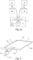
- FIG. 2c there are shown three regulators 25a, 25b, 25c.
- the first regulator 25a is regulating the pressure for the first group of air cushion members 2a and 2c
- the second regulator is regulating the pressure of the second group of air cushion members 2b, 2d.
- the third regulator is regulating the flow into the first group of air cushion members 2a, 2c. This illustrates different regulators for different groups of air cushion members.
- FIG. 2b a three branch system as in FIG. 2b is optionally be provided with various numbers of regulators.
- the considerations and examples with respect to regulators apply equally well for the other embodiments and examples shown and discussed.
- the principles of FIG. 2a and FIG. 2b are optionally provided with four, five, six or more air cushion members.
- the controller 8 is optionally programmed with several sequential programs for inflating and deflating the various air cushion members 2a, 2b, 2c in dependence on the sequential programs. Sequences with sequential inflating and deflating as described above in connection with FIG. 1a can performed by the arrangement in FIG. 2 if reduced to two air cushion members. Likewise inflation and deflation sequences can be performed for more than two air cushion members connected to the regulator unit 11. Alternatively to the two or three air cushion members 2a, 2b, 2c, as illustrated in FIG. 2a and FIG. 2b , some or all of the air cushion members 2a, 2b, 2c are alternatively substituted by air cushion member groups. This principle for two groups with each two air cushion members is illustrated in principle in FIG. 2c .
- a first group of air cushion members 2a, 2c and a second group of air cushion members 2b, 2d are provided.
- three groups of air cushion members are optionally provided or even more than three groups, for example four, five, six, or more groups.
- each of the groups of air cushion members comprises more than two air cushion members.
- one group can have a different number of air cushion members than another group.
- Fig. 3 illustrates an air cushion member 2 for the device 1 according to the invention.
- the air cushion member 2 comprises a folded rectangular piece of a sheet material and has a form as a rectangle.
- the sheet material is joined along an edge region 13 such that the fold 12 constitutes one edge 13a of the rectangle and the edge region 13 constitutes three other edges 13b, 13c, 13d of the rectangle.
- the sheet material is easily flexible, but non-stretchable.
- the sheet material is a plastic sheet, reinforced with fibers, optionally glass, polymer, or carbon fibers.
- a foot piece of an outwardly projecting, flexible first hose 5a for connection with the common air pump 6.
- a deflation valve 9a is provided on the first hose 5a in the form of a bleeding valve with an actuator button 14.
- the bleeding valve 9a is for sake of illustration in the figure drawn as being close to the cushion member 2. However, it is optionally provided at a larger distance to the air cushion member 2, for example close to the inflation tool 4.
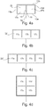
- Fig. 4a-4d illustrate air cushion members which are not in accordance with the invention.
- FIG. 4a illustrates an air cushion member 22 similar to the one in FIG. 3 but with a central joint 15, which joins the two opposite layers of sheet material of the air cushion member 22.
- Such joint 15 is typically made by welding, although gluing is another option.
- the joint 15 extends from the center of one edge 13b towards the center of the opposite edge 13a but does not extend entirely to the opposite edge 13a, because there must be an air flow connection 16 such that air from the first hose 5a can fill the two partial volumes 17a, 17b in either side of the joint 15.
- FIG. 4b illustrates an air cushion member 22' with three partial volumes 17a, 17b, 17c partially separated by two joints
- FIG. 4c illustrates an air cushion member 22' with four partial volumes 17a, 17b, 17c, 17d partially separated by three joints
- FIG. 4d illustrates an air cushion member 22' with four partial volumes 17a, 17b, 17c, 17d, partially separated by a cross joint.
- Such joints limit the deformation such that the air cushion member with joint has a smaller maximum thickness as compared to one of an equal size but without joint. Also, the joints result in a more flat shape when fully inflated.
- FIG. 5 illustrates possible embodiments for the T-piece connector 3, the cross connector 10, a Y-piece connector 3' as alternative to the T-piece connector 3, and a piece of tube 5a. These components are used for assembling systems according to FIG. 1 and FIG. 2 and are optionally provided in an assembly set that also comprises a plurality of air cushion members 2, 22, 22', 22".
- FIG. 6 illustrates various common air pumps, namely a hand operated balloon 6', a bellows 6", for example foot-operated, or an electrical compressor pump 6"'.
- a hand operated balloon 6' a bellows 6"
- an electrical compressor pump 6"' a pump for example a hand operated balloon 6'
- three hoses of a hose-connection 5 are connected by quick couplings 24 to a manifold 23 for inflation of three air cushion members or three groups of air cushion
- the manifold 23 is provided with regulation options, in which case the manifold also comprises regulator unit 11 of the type as indicated in FIG. 2 .
- the device according to the invention is suitable for lifting and adjusting a variety of elements, for example frames, doors, windows, walls, furniture, and machines.
- FIG. 7 a prior art drawing is shown with air cushion members 2, each being connected to its air pumping balloon.
- a device as described above is suitable for such use, where the two left air cushion members and the two right air cushion members form two groups that are inflated by respective hoses, for example as illustrated in FIG. 2c , where the left group and the right group of air cushion members are inflated differently and adjustable.
- the two wedges 7 in FIG. 7 can thus be substituted by a system in FIG. 1a, FIG. 1b , or FIG. 2a , depending on whether the window has to be lifted and lowered identically or differentially.
- the system in FIG. 2b is provided with six air cushion members that can be inflated, deflated, and regulated individually; such system is suitable for substituting the four air cushion members 2 in FIG.7 as well as the two wedges 7.
Landscapes
- Engineering & Computer Science (AREA)
- Architecture (AREA)
- Structural Engineering (AREA)
- Life Sciences & Earth Sciences (AREA)
- Geology (AREA)
- Mechanical Engineering (AREA)
- Civil Engineering (AREA)
- Mattresses And Other Support Structures For Chairs And Beds (AREA)
Claims (12)
- Vorrichtung (1) zum Positionieren einer Tür oder eines Fensters relativ zu einer Oberfläche, wobei die Vorrichtung (1) eine Vielzahl von aufblasbaren Luftpolsterelementen (2) aus einem flexiblen, jedoch nicht dehnbaren luftdichten Bahnmaterial in Schlauchverbindung (5) mit einem Aufblaswerkzeug (4) umfasst; wobei jedes aufblasbare Luftpolsterelement (2) als eine Beuteleinheit ausgebildet ist, die gegenüberliegende Schichten des Bahnmaterials umfasst, die gegenüber voneinander vorgesehen und entlang eines Randbereichs verbunden sind, um eine Doppelschichtrandregion (13) zu bilden; wobei die Beuteleinheit im entleerten Zustand flach ist; wobei die Luftpolsterelemente (2) der Vielzahl von aufblasbaren Luftpolsterelementen voneinander getrennt sind, sodass der Randbereich eines ersten Polsterelements (2a) der Vielzahl von aufblasbaren Luftpolsterelementen (2) von dem Randbereich eines zweiten Polsterelements (2b) der einen Vielzahl von aufblasbaren Luftpolsterelementen (2) vollständig disjunkt ist; wobei das erste (2a) und zweite Polsterelement (2b) durch die Schlauchverbindung (5) mit einer gemeinsamen Luftpumpe (6) als Teil des Aufblaswerkzeugs (4) verbunden sind, wobei die gemeinsame Luftpumpe (6) zum Aufblasen des ersten (2a) und zweiten Polsterelements (2b) konfiguriert ist, dadurch gekennzeichnet, dass jedes Luftpolsterelement (2) ein rechteckiges Stück eines gefalteten Bahnmaterials umfasst, das als ein Rechteck mit einem Falz (12) ausgebildet ist, wobei das Bahnmaterial verbunden ist, um eine Doppelschicht lediglich entlang der Randregion (13) zu bilden und so verbunden ist, dass der Falz (12) einen Rand (13a) des Rechtecks bildet und die verbundene Doppelschichtrandregion (13) drei andere Ränder (13b, 13c, 13d) des Rechtecks bildet, wobei ein Fußstück eines nach außen hervorstehenden, flexiblen ersten Schlauchs (5a) an dem Falz (12) für die Schlauchverbindung (5) vorgesehen ist.
- Vorrichtung nach Anspruch 1, wobei die Vorrichtung zum gleichzeitigen Aufblasen des ersten (2a) und zweiten (2b) Polsterelements durch die gemeinsame Luftpumpe (6) konfiguriert ist.
- Vorrichtung nach Anspruch 1, wobei das Aufblaswerkzeug (4) konfiguriert ist, um das erste (2a) und zweite (2b) Polsterelement der Reihe nach durch die gemeinsame Luftpumpe (6) aufzublasen.
- Vorrichtung nach Anspruch 3, wobei die Vorrichtung (1) für eine Reihenfolge des Aufblasens durch die gemeinsame Luftpumpe (6) konfiguriert ist, wobei die Reihenfolge das Aufblasen des ersten Polsterelements (2a) durch die gemeinsame Pumpe (6) umfasst, während das zweite Polsterelement (2b) entleert ist; anschließend wird das zweite Polsterelement (2b) durch die gemeinsame Luftpumpe (6) aufgeblasen.
- Vorrichtung nach Anspruch 4, wobei die Vorrichtung (1) konfiguriert ist, um das erste Polsterelement (2a) vor dem Aufblasen des zweiten Polsterelements (2b) zu entleeren.
- Vorrichtung nach Anspruch 1, wobei die Vorrichtung (1) für eine Reihenfolge des Aufblasens und Entleerens des ersten Polsterelements (2a), gefolgt von einem Aufblasen und Entleeren des zweiten Polsterelements (2b), konfiguriert ist.
- Vorrichtung nach Anspruch 1, wobei das Aufblaswerkzeug (4) für eine selektive Verschiebung zwischen einem ersten Aufblasmodus und einem zweiten Aufblasmodus durch die gemeinsame Luftpumpe (6) konfiguriert ist; wobei der erste Modus einem gleichzeitigen Aufblasen des ersten und zweiten Polsterelements (2a, 2b) entspricht und der zweite Modus einem Aufblasen des ersten und zweiten Polsterelements (2a, 2b) der Reihe nach eins nach dem anderen entspricht.
- Vorrichtung nach Anspruch 1, wobei die Vorrichtung (1) eine erste Gruppe von mehreren Luftpolsterelementen (2) und eine zweite Gruppe von mehreren Luftpolsterelementen (2) umfasst, wobei die erste und die zweite Gruppe Untergruppen der Vielzahl von aufblasbaren Luftpolsterelementen sind; wobei das Aufblaswerkzeug (4) konfiguriert ist, um die zwei Untergruppen eine nach der anderen aufzublasen.
- Vorrichtung nach Anspruch 1, wobei die Vorrichtung (1) einen Regler (11) umfasst, der einen Lufteinlass aufweist, der mit der gemeinsamen Pumpe (6) verbunden ist, sowie einen ersten und einen zweiten Luftauslass, wobei der erste Luftauslass mit dem ersten Luftpolsterelement (2a) oder mit einer ersten Gruppe von Luftpolsterelementen verbunden ist und der zweite Auslass mit dem zweiten Luftpolsterelement (2b) oder mit einer zweiten Gruppe von Luftpolsterelementen verbunden ist; wobei der Regler (11) verstellbar ist, um selektiv eines oder das andere des ersten und zweiten Luftpolsterelements (2a, 2b) oder eine Gruppe von Luftpolsterelementen gleichzeitig aufzublasen.
- Bausatz für eine Vorrichtung nach Anspruch 1, wobei der Bausatz eine Vielzahl von Luftpolsterelementen (2) nach Anspruch 1, mindestens zwei Schläuche (5a, 5b) und mindestens einen T-Stück-Verbinder (3) oder Querverbinder (10) umfasst, der zu den Schläuchen (5a, 5b) passt, um die Luftpolsterelemente in Schlauchverbindung über die Schläuche mit einer gemeinsamen Luftpumpe zu verbinden.
- Verfahren zum Betrieb einer Vorrichtung zum Positionieren einer Tür oder eines Fensters relativ zu einer Oberfläche, wobei die Vorrichtung (1) eine Vielzahl von aufblasbaren Luftpolsterelementen (2) aus einem flexiblen, jedoch nicht dehnbaren luftdichten Bahnmaterial in Schlauchverbindung (5) mit einem Aufblaswerkzeug (4) umfasst; wobei jedes aufblasbare Luftpolsterelement (2) als eine Beuteleinheit ausgebildet ist, die gegenüberliegende Schichten des Bahnmaterials umfasst, die gegenüber voneinander vorgesehen und entlang eines Randbereichs verbunden sind, um eine Doppelschichtrandregion (13) zu bilden; wobei die Beuteleinheit im entleerten Zustand flach ist; wobei jedes Luftpolsterelement (2) ein rechteckiges Stück eines gefalteten Bahnmaterials umfasst, das als ein Rechteck mit einem Falz (12) ausgebildet ist, wobei das Bahnmaterial verbunden ist, um eine Doppelschicht lediglich entlang der Randregion (13) zu bilden und so verbunden ist, dass der Falz (12) einen Rand (13a) des Rechtecks bildet und die verbundene Doppelschichtrandregion (13) drei andere Ränder (13b, 13c, 13d) des Rechtecks bildet, wobei ein Fußstück eines nach außen hervorstehenden, flexiblen ersten Schlauchs (5a) an dem Falz (12) für die Schlauchverbindung (5) vorgesehen ist, wobei das Verfahren das Bereitstellen der Luftpolsterelemente (2) der Vielzahl von aufblasbaren Luftpolsterelementen (2) getrennt voneinander umfasst, sodass der Randbereich eines ersten Polsterelements (2a) der Vielzahl von aufblasbaren Luftpolsterelementen von dem Randbereich eines zweiten Polsterelements (2b) der einen Vielzahl von aufblasbaren Luftpolsterelementen (2) vollständig disjunkt ist; wobei das erste und zweite Polsterelement (2a, 2b) durch die Schlauchverbindung (5) mit einer gemeinsamen Luftpumpe (6) als Teil des Aufblaswerkzeugs (4) verbunden sind und das erste und zweite Polsterelement (2a, 2b) aufgeblasen werden.
- Verfahren nach Anspruch 11, wobei das Verfahren das Aufblasen des ersten Polsterelements (2a) umfasst, während das zweite Polsterelement (2b) entleert ist und dann das erste Polsterelement (2a) entleert wird; anschließend Aufblasen des zweiten Polsterelements (2b) während das erste Polsterelement (2a) entleert ist und dann Entleeren des zweiten Polsterelements (2b) zu einem Zustand, in dem das erste und das zweite Polsterelement (2a, 2b) beide entleert sind.
Applications Claiming Priority (3)
| Application Number | Priority Date | Filing Date | Title |
|---|---|---|---|
| DKPA201470636 | 2014-10-13 | ||
| US201462063481P | 2014-10-14 | 2014-10-14 | |
| PCT/DK2015/050315 WO2016058614A1 (en) | 2014-10-13 | 2015-10-13 | A device for positioning an element relatively to a surface and method for operating such device |
Publications (3)
| Publication Number | Publication Date |
|---|---|
| EP3206985A1 EP3206985A1 (de) | 2017-08-23 |
| EP3206985A4 EP3206985A4 (de) | 2018-06-27 |
| EP3206985B1 true EP3206985B1 (de) | 2021-12-22 |
Family
ID=55746155
Family Applications (1)
| Application Number | Title | Priority Date | Filing Date |
|---|---|---|---|
| EP15850794.7A Active EP3206985B1 (de) | 2014-10-13 | 2015-10-13 | Vorrichtung zum positionieren eines elements relativ zu einer oberfläche, verfahren zum betrieb solch einer vorrichtung, und bausatz dafür |
Country Status (3)
| Country | Link |
|---|---|
| EP (1) | EP3206985B1 (de) |
| DK (1) | DK3206985T3 (de) |
| WO (1) | WO2016058614A1 (de) |
Cited By (1)
| Publication number | Priority date | Publication date | Assignee | Title |
|---|---|---|---|---|
| SE2351522A1 (en) * | 2023-12-28 | 2025-06-29 | Lysekilen Ab | Lifting bag |
Families Citing this family (3)
| Publication number | Priority date | Publication date | Assignee | Title |
|---|---|---|---|---|
| DK180626B1 (en) * | 2016-11-11 | 2021-11-04 | Dissing As | A device for positioning an object relatively to a support by inflatable air cushion members, a method of operating the device, and a method for moving an object |
| US11814273B2 (en) | 2019-05-09 | 2023-11-14 | Dissing A/S | Device for positioning an object relatively to a support by an inflatable air cushion member in combination with a support block |
| DE202019004148U1 (de) * | 2019-10-09 | 2021-01-13 | Ernstfried Prade | Vorrichtung für geteilten Luftstrom |
Citations (3)
| Publication number | Priority date | Publication date | Assignee | Title |
|---|---|---|---|---|
| WO1985002648A1 (fr) * | 1983-12-08 | 1985-06-20 | Bernd Ludwig | Procede et installation pour aligner un element, comme un cadre, a introduire par exemple dans un evidement de mur |
| WO1995013448A1 (en) * | 1993-11-10 | 1995-05-18 | Mogens Laurits Jensen | A method and an accessory for mounting building frames such as window frames in mounting openings |
| GB2286430A (en) * | 1994-02-11 | 1995-08-16 | Mangar Aids Ltd | Lifting devices |
Family Cites Families (8)
| Publication number | Priority date | Publication date | Assignee | Title |
|---|---|---|---|---|
| GB1604141A (en) | 1978-01-05 | 1981-12-02 | Modern Precision Engs & Associ | Air cushion lifting device |
| GB8323675D0 (en) * | 1983-09-03 | 1983-10-05 | Snell T B | Lifting devices |
| US5232202A (en) * | 1991-09-12 | 1993-08-03 | Watson Alan R | Tank lifting methods |
| JPH0654739A (ja) | 1992-04-30 | 1994-03-01 | Yoshihisa Yamaguchi | ベッド |
| DE29717506U1 (de) | 1997-09-22 | 1999-01-28 | Ludwig, Bernd, 63517 Rodenbach | Montageeinrichtung |
| FR2839711B1 (fr) | 2002-05-14 | 2005-08-19 | Regie Autonome Transports | Dispositif de deplacement d'une charge reposant sur le sol |
| US20040217338A1 (en) | 2003-04-30 | 2004-11-04 | Abrahamson Guy A. | Device and method for leveling recreational vehicles |
| DK178296B1 (da) * | 2014-08-08 | 2015-11-09 | Dissing As | Hjælpeværktøj til brug ved placering af elementer i forhold til en tilstødende flade |
-
2015
- 2015-10-13 WO PCT/DK2015/050315 patent/WO2016058614A1/en not_active Ceased
- 2015-10-13 DK DK15850794.7T patent/DK3206985T3/da active
- 2015-10-13 EP EP15850794.7A patent/EP3206985B1/de active Active
Patent Citations (3)
| Publication number | Priority date | Publication date | Assignee | Title |
|---|---|---|---|---|
| WO1985002648A1 (fr) * | 1983-12-08 | 1985-06-20 | Bernd Ludwig | Procede et installation pour aligner un element, comme un cadre, a introduire par exemple dans un evidement de mur |
| WO1995013448A1 (en) * | 1993-11-10 | 1995-05-18 | Mogens Laurits Jensen | A method and an accessory for mounting building frames such as window frames in mounting openings |
| GB2286430A (en) * | 1994-02-11 | 1995-08-16 | Mangar Aids Ltd | Lifting devices |
Cited By (2)
| Publication number | Priority date | Publication date | Assignee | Title |
|---|---|---|---|---|
| SE2351522A1 (en) * | 2023-12-28 | 2025-06-29 | Lysekilen Ab | Lifting bag |
| EP4582367A1 (de) * | 2023-12-28 | 2025-07-09 | Lysekilen AB | Hebetasche |
Also Published As
| Publication number | Publication date |
|---|---|
| DK3206985T3 (da) | 2022-03-28 |
| WO2016058614A1 (en) | 2016-04-21 |
| EP3206985A4 (de) | 2018-06-27 |
| EP3206985A1 (de) | 2017-08-23 |
Similar Documents
| Publication | Publication Date | Title |
|---|---|---|
| EP3206985B1 (de) | Vorrichtung zum positionieren eines elements relativ zu einer oberfläche, verfahren zum betrieb solch einer vorrichtung, und bausatz dafür | |
| US8650686B2 (en) | Adjustable width bariatric transport support surface | |
| AU2017358322B2 (en) | A device for positioning an object relatively to a support by inflatable air cushion members, a method of operating the device, and a method for moving an object | |
| US20160213553A1 (en) | Massage system for a vehicle seat | |
| US20190090644A1 (en) | Camp air chair | |
| JP7280932B2 (ja) | 隣接した平坦部または平面に関して要素を位置決めするための補助取付けツール | |
| EP3354249B1 (de) | Patiententragevorrichtung | |
| US9504620B2 (en) | Method of controlling a pressurized mattress system for a support structure | |
| WO2008091455A3 (en) | Bedding or seating product having inflatable concentric air bladders | |
| US10327971B2 (en) | Bidirectional fluid flow valve and method | |
| US20250134269A1 (en) | Modular pneumatic actuation system for adjustable support | |
| WO2020174418A1 (en) | Patient positioning apparatus and mattress | |
| CN109696015B (zh) | 冰箱调平装置、方法及冰箱 | |
| WO2017032973A1 (en) | Inflatable support | |
| WO2016058615A1 (en) | A mattress with a lifting mechanism and a method for lifting a mattress | |
| EP4076329B1 (de) | Stützflächenauflage mit vakuumgehäuse | |
| AU2011100535A4 (en) | Mattress lift system | |
| AU2021252507B2 (en) | Expandable patient support apparatus and method | |
| US9527367B2 (en) | Pneumatic actuators | |
| US20250090399A1 (en) | Alternate pressure mattress system and methods of use | |
| JP2006212257A (ja) | マッサージ機 | |
| AU2025201310A1 (en) | Patient support surface having a pneumatic control assembly | |
| WO2023079440A1 (en) | A load moving device |
Legal Events
| Date | Code | Title | Description |
|---|---|---|---|
| STAA | Information on the status of an ep patent application or granted ep patent |
Free format text: STATUS: THE INTERNATIONAL PUBLICATION HAS BEEN MADE |
|
| PUAI | Public reference made under article 153(3) epc to a published international application that has entered the european phase |
Free format text: ORIGINAL CODE: 0009012 |
|
| STAA | Information on the status of an ep patent application or granted ep patent |
Free format text: STATUS: REQUEST FOR EXAMINATION WAS MADE |
|
| 17P | Request for examination filed |
Effective date: 20170426 |
|
| AK | Designated contracting states |
Kind code of ref document: A1 Designated state(s): AL AT BE BG CH CY CZ DE DK EE ES FI FR GB GR HR HU IE IS IT LI LT LU LV MC MK MT NL NO PL PT RO RS SE SI SK SM TR |
|
| AX | Request for extension of the european patent |
Extension state: BA ME |
|
| DAV | Request for validation of the european patent (deleted) | ||
| DAX | Request for extension of the european patent (deleted) | ||
| A4 | Supplementary search report drawn up and despatched |
Effective date: 20180528 |
|
| RIC1 | Information provided on ipc code assigned before grant |
Ipc: E04F 21/00 20060101ALI20180522BHEP Ipc: B66F 3/35 20060101AFI20180522BHEP |
|
| STAA | Information on the status of an ep patent application or granted ep patent |
Free format text: STATUS: EXAMINATION IS IN PROGRESS |
|
| 17Q | First examination report despatched |
Effective date: 20190919 |
|
| GRAP | Despatch of communication of intention to grant a patent |
Free format text: ORIGINAL CODE: EPIDOSNIGR1 |
|
| STAA | Information on the status of an ep patent application or granted ep patent |
Free format text: STATUS: GRANT OF PATENT IS INTENDED |
|
| INTG | Intention to grant announced |
Effective date: 20210901 |
|
| GRAS | Grant fee paid |
Free format text: ORIGINAL CODE: EPIDOSNIGR3 |
|
| GRAA | (expected) grant |
Free format text: ORIGINAL CODE: 0009210 |
|
| STAA | Information on the status of an ep patent application or granted ep patent |
Free format text: STATUS: THE PATENT HAS BEEN GRANTED |
|
| AK | Designated contracting states |
Kind code of ref document: B1 Designated state(s): AL AT BE BG CH CY CZ DE DK EE ES FI FR GB GR HR HU IE IS IT LI LT LU LV MC MK MT NL NO PL PT RO RS SE SI SK SM TR |
|
| REG | Reference to a national code |
Ref country code: GB Ref legal event code: FG4D |
|
| REG | Reference to a national code |
Ref country code: CH Ref legal event code: EP |
|
| REG | Reference to a national code |
Ref country code: DE Ref legal event code: R096 Ref document number: 602015075981 Country of ref document: DE |
|
| REG | Reference to a national code |
Ref country code: AT Ref legal event code: REF Ref document number: 1456950 Country of ref document: AT Kind code of ref document: T Effective date: 20220115 |
|
| REG | Reference to a national code |
Ref country code: IE Ref legal event code: FG4D |
|
| REG | Reference to a national code |
Ref country code: DK Ref legal event code: T3 Effective date: 20220324 |
|
| REG | Reference to a national code |
Ref country code: NL Ref legal event code: FP |
|
| REG | Reference to a national code |
Ref country code: LT Ref legal event code: MG9D |
|
| REG | Reference to a national code |
Ref country code: SE Ref legal event code: TRGR |
|
| PG25 | Lapsed in a contracting state [announced via postgrant information from national office to epo] |
Ref country code: RS Free format text: LAPSE BECAUSE OF FAILURE TO SUBMIT A TRANSLATION OF THE DESCRIPTION OR TO PAY THE FEE WITHIN THE PRESCRIBED TIME-LIMIT Effective date: 20211222 Ref country code: LT Free format text: LAPSE BECAUSE OF FAILURE TO SUBMIT A TRANSLATION OF THE DESCRIPTION OR TO PAY THE FEE WITHIN THE PRESCRIBED TIME-LIMIT Effective date: 20211222 Ref country code: FI Free format text: LAPSE BECAUSE OF FAILURE TO SUBMIT A TRANSLATION OF THE DESCRIPTION OR TO PAY THE FEE WITHIN THE PRESCRIBED TIME-LIMIT Effective date: 20211222 Ref country code: BG Free format text: LAPSE BECAUSE OF FAILURE TO SUBMIT A TRANSLATION OF THE DESCRIPTION OR TO PAY THE FEE WITHIN THE PRESCRIBED TIME-LIMIT Effective date: 20220322 |
|
| REG | Reference to a national code |
Ref country code: AT Ref legal event code: MK05 Ref document number: 1456950 Country of ref document: AT Kind code of ref document: T Effective date: 20211222 |
|
| PG25 | Lapsed in a contracting state [announced via postgrant information from national office to epo] |
Ref country code: NO Free format text: LAPSE BECAUSE OF FAILURE TO SUBMIT A TRANSLATION OF THE DESCRIPTION OR TO PAY THE FEE WITHIN THE PRESCRIBED TIME-LIMIT Effective date: 20220322 Ref country code: LV Free format text: LAPSE BECAUSE OF FAILURE TO SUBMIT A TRANSLATION OF THE DESCRIPTION OR TO PAY THE FEE WITHIN THE PRESCRIBED TIME-LIMIT Effective date: 20211222 Ref country code: HR Free format text: LAPSE BECAUSE OF FAILURE TO SUBMIT A TRANSLATION OF THE DESCRIPTION OR TO PAY THE FEE WITHIN THE PRESCRIBED TIME-LIMIT Effective date: 20211222 Ref country code: GR Free format text: LAPSE BECAUSE OF FAILURE TO SUBMIT A TRANSLATION OF THE DESCRIPTION OR TO PAY THE FEE WITHIN THE PRESCRIBED TIME-LIMIT Effective date: 20220323 |
|
| PG25 | Lapsed in a contracting state [announced via postgrant information from national office to epo] |
Ref country code: SM Free format text: LAPSE BECAUSE OF FAILURE TO SUBMIT A TRANSLATION OF THE DESCRIPTION OR TO PAY THE FEE WITHIN THE PRESCRIBED TIME-LIMIT Effective date: 20211222 Ref country code: SK Free format text: LAPSE BECAUSE OF FAILURE TO SUBMIT A TRANSLATION OF THE DESCRIPTION OR TO PAY THE FEE WITHIN THE PRESCRIBED TIME-LIMIT Effective date: 20211222 Ref country code: RO Free format text: LAPSE BECAUSE OF FAILURE TO SUBMIT A TRANSLATION OF THE DESCRIPTION OR TO PAY THE FEE WITHIN THE PRESCRIBED TIME-LIMIT Effective date: 20211222 Ref country code: PT Free format text: LAPSE BECAUSE OF FAILURE TO SUBMIT A TRANSLATION OF THE DESCRIPTION OR TO PAY THE FEE WITHIN THE PRESCRIBED TIME-LIMIT Effective date: 20220422 Ref country code: ES Free format text: LAPSE BECAUSE OF FAILURE TO SUBMIT A TRANSLATION OF THE DESCRIPTION OR TO PAY THE FEE WITHIN THE PRESCRIBED TIME-LIMIT Effective date: 20211222 Ref country code: EE Free format text: LAPSE BECAUSE OF FAILURE TO SUBMIT A TRANSLATION OF THE DESCRIPTION OR TO PAY THE FEE WITHIN THE PRESCRIBED TIME-LIMIT Effective date: 20211222 Ref country code: CZ Free format text: LAPSE BECAUSE OF FAILURE TO SUBMIT A TRANSLATION OF THE DESCRIPTION OR TO PAY THE FEE WITHIN THE PRESCRIBED TIME-LIMIT Effective date: 20211222 |
|
| PG25 | Lapsed in a contracting state [announced via postgrant information from national office to epo] |
Ref country code: PL Free format text: LAPSE BECAUSE OF FAILURE TO SUBMIT A TRANSLATION OF THE DESCRIPTION OR TO PAY THE FEE WITHIN THE PRESCRIBED TIME-LIMIT Effective date: 20211222 Ref country code: AT Free format text: LAPSE BECAUSE OF FAILURE TO SUBMIT A TRANSLATION OF THE DESCRIPTION OR TO PAY THE FEE WITHIN THE PRESCRIBED TIME-LIMIT Effective date: 20211222 |
|
| REG | Reference to a national code |
Ref country code: DE Ref legal event code: R097 Ref document number: 602015075981 Country of ref document: DE |
|
| PG25 | Lapsed in a contracting state [announced via postgrant information from national office to epo] |
Ref country code: IS Free format text: LAPSE BECAUSE OF FAILURE TO SUBMIT A TRANSLATION OF THE DESCRIPTION OR TO PAY THE FEE WITHIN THE PRESCRIBED TIME-LIMIT Effective date: 20220422 |
|
| PLBE | No opposition filed within time limit |
Free format text: ORIGINAL CODE: 0009261 |
|
| STAA | Information on the status of an ep patent application or granted ep patent |
Free format text: STATUS: NO OPPOSITION FILED WITHIN TIME LIMIT |
|
| PG25 | Lapsed in a contracting state [announced via postgrant information from national office to epo] |
Ref country code: AL Free format text: LAPSE BECAUSE OF FAILURE TO SUBMIT A TRANSLATION OF THE DESCRIPTION OR TO PAY THE FEE WITHIN THE PRESCRIBED TIME-LIMIT Effective date: 20211222 |
|
| 26N | No opposition filed |
Effective date: 20220923 |
|
| PG25 | Lapsed in a contracting state [announced via postgrant information from national office to epo] |
Ref country code: SI Free format text: LAPSE BECAUSE OF FAILURE TO SUBMIT A TRANSLATION OF THE DESCRIPTION OR TO PAY THE FEE WITHIN THE PRESCRIBED TIME-LIMIT Effective date: 20211222 |
|
| PG25 | Lapsed in a contracting state [announced via postgrant information from national office to epo] |
Ref country code: MC Free format text: LAPSE BECAUSE OF FAILURE TO SUBMIT A TRANSLATION OF THE DESCRIPTION OR TO PAY THE FEE WITHIN THE PRESCRIBED TIME-LIMIT Effective date: 20211222 |
|
| REG | Reference to a national code |
Ref country code: BE Ref legal event code: MM Effective date: 20221031 |
|
| PG25 | Lapsed in a contracting state [announced via postgrant information from national office to epo] |
Ref country code: LU Free format text: LAPSE BECAUSE OF NON-PAYMENT OF DUE FEES Effective date: 20221013 |
|
| P01 | Opt-out of the competence of the unified patent court (upc) registered |
Effective date: 20230530 |
|
| PG25 | Lapsed in a contracting state [announced via postgrant information from national office to epo] |
Ref country code: BE Free format text: LAPSE BECAUSE OF NON-PAYMENT OF DUE FEES Effective date: 20221031 |
|
| PG25 | Lapsed in a contracting state [announced via postgrant information from national office to epo] |
Ref country code: IE Free format text: LAPSE BECAUSE OF NON-PAYMENT OF DUE FEES Effective date: 20221013 |
|
| PG25 | Lapsed in a contracting state [announced via postgrant information from national office to epo] |
Ref country code: HU Free format text: LAPSE BECAUSE OF FAILURE TO SUBMIT A TRANSLATION OF THE DESCRIPTION OR TO PAY THE FEE WITHIN THE PRESCRIBED TIME-LIMIT; INVALID AB INITIO Effective date: 20151013 |
|
| PG25 | Lapsed in a contracting state [announced via postgrant information from national office to epo] |
Ref country code: CY Free format text: LAPSE BECAUSE OF FAILURE TO SUBMIT A TRANSLATION OF THE DESCRIPTION OR TO PAY THE FEE WITHIN THE PRESCRIBED TIME-LIMIT Effective date: 20211222 |
|
| PG25 | Lapsed in a contracting state [announced via postgrant information from national office to epo] |
Ref country code: MK Free format text: LAPSE BECAUSE OF FAILURE TO SUBMIT A TRANSLATION OF THE DESCRIPTION OR TO PAY THE FEE WITHIN THE PRESCRIBED TIME-LIMIT Effective date: 20211222 |
|
| PG25 | Lapsed in a contracting state [announced via postgrant information from national office to epo] |
Ref country code: TR Free format text: LAPSE BECAUSE OF FAILURE TO SUBMIT A TRANSLATION OF THE DESCRIPTION OR TO PAY THE FEE WITHIN THE PRESCRIBED TIME-LIMIT Effective date: 20211222 |
|
| PG25 | Lapsed in a contracting state [announced via postgrant information from national office to epo] |
Ref country code: MT Free format text: LAPSE BECAUSE OF FAILURE TO SUBMIT A TRANSLATION OF THE DESCRIPTION OR TO PAY THE FEE WITHIN THE PRESCRIBED TIME-LIMIT Effective date: 20211222 |
|
| REG | Reference to a national code |
Ref country code: CH Ref legal event code: U11 Free format text: ST27 STATUS EVENT CODE: U-0-0-U10-U11 (AS PROVIDED BY THE NATIONAL OFFICE) Effective date: 20251101 |
|
| PGFP | Annual fee paid to national office [announced via postgrant information from national office to epo] |
Ref country code: NL Payment date: 20251026 Year of fee payment: 11 |
|
| PGFP | Annual fee paid to national office [announced via postgrant information from national office to epo] |
Ref country code: DE Payment date: 20251029 Year of fee payment: 11 |
|
| PGFP | Annual fee paid to national office [announced via postgrant information from national office to epo] |
Ref country code: GB Payment date: 20251027 Year of fee payment: 11 |
|
| PGFP | Annual fee paid to national office [announced via postgrant information from national office to epo] |
Ref country code: DK Payment date: 20251027 Year of fee payment: 11 Ref country code: IT Payment date: 20251021 Year of fee payment: 11 |
|
| PGFP | Annual fee paid to national office [announced via postgrant information from national office to epo] |
Ref country code: FR Payment date: 20251027 Year of fee payment: 11 |
|
| PGFP | Annual fee paid to national office [announced via postgrant information from national office to epo] |
Ref country code: SE Payment date: 20251027 Year of fee payment: 11 Ref country code: CH Payment date: 20251101 Year of fee payment: 11 |