EP3207183B1 - Dispositif de lame racleuse à segments de lame juxtaposés présentant un raccordement à pivot entre bords de contact - Google Patents
Dispositif de lame racleuse à segments de lame juxtaposés présentant un raccordement à pivot entre bords de contact Download PDFInfo
- Publication number
- EP3207183B1 EP3207183B1 EP15851592.4A EP15851592A EP3207183B1 EP 3207183 B1 EP3207183 B1 EP 3207183B1 EP 15851592 A EP15851592 A EP 15851592A EP 3207183 B1 EP3207183 B1 EP 3207183B1
- Authority
- EP
- European Patent Office
- Prior art keywords
- blade
- scraper blade
- segments
- blade device
- scraper
- Prior art date
- Legal status (The legal status is an assumption and is not a legal conclusion. Google has not performed a legal analysis and makes no representation as to the accuracy of the status listed.)
- Active
Links
Images




Classifications
-
- E—FIXED CONSTRUCTIONS
- E01—CONSTRUCTION OF ROADS, RAILWAYS, OR BRIDGES
- E01H—STREET CLEANING; CLEANING OF PERMANENT WAYS; CLEANING BEACHES; DISPERSING OR PREVENTING FOG IN GENERAL CLEANING STREET OR RAILWAY FURNITURE OR TUNNEL WALLS
- E01H5/00—Removing snow or ice from roads or like surfaces; Grading or roughening snow or ice
- E01H5/04—Apparatus propelled by animal or engine power; Apparatus propelled by hand with driven dislodging or conveying levelling elements, conveying pneumatically for the dislodged material
- E01H5/06—Apparatus propelled by animal or engine power; Apparatus propelled by hand with driven dislodging or conveying levelling elements, conveying pneumatically for the dislodged material dislodging essentially by non-driven elements, e.g. scraper blades, snow-plough blades, scoop blades
- E01H5/061—Apparatus propelled by animal or engine power; Apparatus propelled by hand with driven dislodging or conveying levelling elements, conveying pneumatically for the dislodged material dislodging essentially by non-driven elements, e.g. scraper blades, snow-plough blades, scoop blades by scraper blades
- E01H5/062—Apparatus propelled by animal or engine power; Apparatus propelled by hand with driven dislodging or conveying levelling elements, conveying pneumatically for the dislodged material dislodging essentially by non-driven elements, e.g. scraper blades, snow-plough blades, scoop blades by scraper blades by scraper blades displaceable for shock-absorbing purposes
-
- E—FIXED CONSTRUCTIONS
- E01—CONSTRUCTION OF ROADS, RAILWAYS, OR BRIDGES
- E01H—STREET CLEANING; CLEANING OF PERMANENT WAYS; CLEANING BEACHES; DISPERSING OR PREVENTING FOG IN GENERAL CLEANING STREET OR RAILWAY FURNITURE OR TUNNEL WALLS
- E01H5/00—Removing snow or ice from roads or like surfaces; Grading or roughening snow or ice
- E01H5/04—Apparatus propelled by animal or engine power; Apparatus propelled by hand with driven dislodging or conveying levelling elements, conveying pneumatically for the dislodged material
- E01H5/06—Apparatus propelled by animal or engine power; Apparatus propelled by hand with driven dislodging or conveying levelling elements, conveying pneumatically for the dislodged material dislodging essentially by non-driven elements, e.g. scraper blades, snow-plough blades, scoop blades
- E01H5/067—Apparatus propelled by animal or engine power; Apparatus propelled by hand with driven dislodging or conveying levelling elements, conveying pneumatically for the dislodged material dislodging essentially by non-driven elements, e.g. scraper blades, snow-plough blades, scoop blades by side-wing snow-plough blades
-
- E—FIXED CONSTRUCTIONS
- E02—HYDRAULIC ENGINEERING; FOUNDATIONS; SOIL SHIFTING
- E02F—DREDGING; SOIL-SHIFTING
- E02F9/00—Component parts of dredgers or soil-shifting machines, not restricted to one of the kinds covered by groups E02F3/00 - E02F7/00
- E02F9/20—Drives; Control devices
- E02F9/22—Hydraulic or pneumatic drives
- E02F9/2264—Arrangements or adaptations of elements for hydraulic drives
- E02F9/2271—Actuators and supports therefor and protection therefor
-
- E—FIXED CONSTRUCTIONS
- E02—HYDRAULIC ENGINEERING; FOUNDATIONS; SOIL SHIFTING
- E02F—DREDGING; SOIL-SHIFTING
- E02F9/00—Component parts of dredgers or soil-shifting machines, not restricted to one of the kinds covered by groups E02F3/00 - E02F7/00
- E02F9/28—Small metalwork for digging elements, e.g. teeth scraper bits
- E02F9/2883—Wear elements for buckets or implements in general
Definitions
- the technical field relates generally to scraper blade devices and methods of cleaning surfaces by removing undesirable materials from these surfaces.
- a surface to be cleaned is a roadway surface on which accumulated some snow and/or ice (which are hereafter generically referred to in a non-limitative manner as "frozen water materials").
- This is traditionally done using a rigid blade having a lowermost edge that is in engagement with the roadway surface.
- the blade is attached to a vehicle, for instance a truck or the like, travelling over the roadway surface.
- a blade is often relatively large so as to maximize the width of the surface cleaned in a single pass.
- Such concept assumes that the roadway surface is perfectly smooth, flat and free of obstructions. In practice, roadway surfaces are not.
- the surface height profile often varies irregularly from one end of the lowermost edge of the blade to the other and the surface height profile varies all the time as the blade moves thereon.
- the lowermost edge is therefore not always fully in engagement with the roadway surface over its entire length, with the result that some frozen water materials tend to remain on the roadway surface at various locations, especially where the surface height is the lowest compared to the immediate surrounding areas. The efficiency of the cleaning is thus reduced.
- de-icing chemicals to melt the remaining frozen water materials so as to complete the cleaning.
- the amounts of de-icing chemicals are generally inversely proportional to efficiency of the cleaning. Thus, if the cleaning is inefficient, more de-icing chemicals are required. This has a direct impact on the operating costs and increases the footprint on the environment.
- Canadian Patent No. 2,796,157 issued on 13 August 2013 to Jimmy Vigneault discloses a scraper blade device where ground-engaging blade segments are independently slidingly movable, in an up and down movement, out of alignment with reference to the bottom edge of the other blade segments so as to keep an optimized contact with the surface to be cleaned in spite of the various height variations across the width resulting from irregularities encountered on the surface as the scraper blade device moves thereon.
- the bottom edge of the blade segments can also be temporarily pivoted towards a tripped reclined position upon impact with an obstruction on the surface to be cleaned so as to mitigate damages to the blade segments and/or to the surface to be cleaned.
- the snow plow for use with a motorized vehicle.
- the snow plow comprises a blade and a blade attachment assembly.
- the blade has a lower edge engageable with a road surface and comprises plurality of blade sections.
- the blade attachment assembly includes a plurality of connector bars and a mounting plate secured to the plow body.
- the present concept involves an approach where the scraper blade device includes one or more sets of juxtaposed blade segments where the blade segments have a swivel interconnection between them.
- the blade segments of each set are pivotally attached side-by-side using a positive arrangement capable of resisting detachment.
- the bottom edges of the blade segments within the same set can be tilted of a few degrees with reference to one another, thereby further increasing the freedom of movement of each blade segment with reference to all the other blade segments on the scraper blade device.
- FIG. 1 is a front view of an example of a scraper blade device 100 incorporating the proposed concept.
- the scraper blade device 100 is shown as mounted in front of a generic vehicle 102 for cleaning a roadway surface 104.
- the model or kind of vehicle for use with the scraper blade device 100 can be different from the one being illustrated in FIG. 1 .
- the scraper blade device 100 is shown as being mounted in front of the vehicle 102, it can also be mounted elsewhere, for instance laterally on the side of a vehicle, under a vehicle or even behind a vehicle.
- FIG. 2 is an enlarged side view of the scraper blade device 100 shown in FIG. 1 .
- the scraper blade device 100 illustrated in FIGS. 1 and 2 is primarily designed for removing frozen water materials from the roadway surface 104. However, one can use the scraper blade device 100 for removing other kinds of loose and/or adhering materials on a surface to clean. Examples include sand, rocks, gravel and earth, to name just a few. One can also clean a surface with the scraper blade device 100 without necessarily mounting it to a vehicle since the scraper blade device 100 can be used in many other applications. One example of another application is to clean the surface of a conveyor belt transporting one or more materials. For the sake of simplicity, the present description refers only to the example of the scraper blade device 100 for removing frozen water materials from the roadway surface 104 but it must be understood that the proposed concept is not necessarily limited to such context. Still, the exact overall shape and configuration of the scraper blade device 100 can vary from one implementation to another. It is not limited to the exact ones being shown in the figures.
- road surface is used herein in a generic manner and designates a surface to be cleaned by the scraper blade device 100.
- This can include, for instance, roadway surfaces made of different materials, for instance asphalt, concrete, stones, gravel, earth, etc.
- the roadway surfaces can be roads for vehicles, parkings, airport runways, sidewalks, etc. Other variants are possible as well.
- the scraper blade device 100 will often have an overall width between 1 m and 8 m. Nevertheless, other dimensions are also possible.
- the scraper blade device 100 of FIGS. 1 and 2 is configured for cleaning roadway surfaces at a relatively slow speed, such as for cleaning parkings or roadways in residential areas.
- a scraper blade device for cleaning highways or the like would generally be shaped with a curved upper portion. Variants are possible as well.
- the illustrated scraper blade device 100 is connected to the vehicle 102 using a generic connection assembly 106.
- the illustrated generic connection assembly 106 has a frame 108 and includes an actuator, for instance a hydraulic actuator 110, for lifting and lowering the lowermost edge 100a ( FIG. 2 ) of the scraper blade device 100 with reference to the roadway surface 104.
- the hydraulic actuator 110 can also control the contact pressure between the lowermost edge 100a and the roadway surface 104 by supporting or not a part of the weight of the scraper blade device 100 in use.
- Some implementations may include skids underneath the scraper blade device 100. These skids can engage the roadway surface 104 to support at least a part of the weight during operation. Other arrangements and variants are possible as well.
- Removing frozen water materials from the roadway surface 104 is generally done as the scraper blade device 100 has its lowermost edge 100a in engagement with the roadway surface 104 and as the vehicle 102 moves, in this case in a forward direction, so as to propel the scraper blade device 100 and push the frozen water materials accumulating in front of the scraper blade device 100.
- the forward direction is shown in FIGS. 1 and at 120.
- the scraper blade device 100 has a front plow surface 122.
- the scraper blade device 100 can allow the frozen water materials to be ejected laterally as the scraper blade device 100 travels in the forward direction 120.
- the forward travel direction 120 is thus not necessarily always perpendicular to the blade device 100 and it can define an angle therewith.
- the frozen water materials can be discharged at one or both ends thereof as the vehicle 102 pushes the scraper blade device 100.
- the scraper blade device 100 can even be articulated, for instance with a vertical hinge at the center, to obtain many possible configurations. Variants are possible as well.
- the frozen water materials accumulating on the front plow surface 122 can simply be pushed over some distance while remaining in front of the scraper blade device 100 before the vehicle 102 backs up and leaves them where they are. Variants are possible as well.
- Some cleaning can also be achieved when moving the scraping blade device 100 in a rearward travel direction but most of the time, the cleaning is done as the vehicle 102 travels in the forward travel direction 120. If the scraper blade device 100 is located at the rear of the vehicle 102, it will be in an inverted position. The front plow surface 122 of such scraper blade device 100 would be facing the rear side of the vehicle 102 and most of the cleaning would thus be done as the vehicle 102 moves backwards.
- reference will only be made to the forward travel direction as being the normal direction to achieve cleaning with the scraper blade device 100, being understood that this forward travel direction may sometimes not correspond to the forward travel direction of a given vehicle, as a person skilled in the art will readily understand.
- the illustrated scraper blade device 100 includes an upper blade portion 130 and a bottom blade portion 132 extending widthwise on the scraper blade device 100.
- the upper blade portion 130 generally defines an upper area of the front plow surface 122.
- the bottom blade portion 132 generally defines a bottom area of the front plow surface 122.
- the frame 108 of the illustrated generic connection assembly 106 is attached at the rear of the upper blade portion 130. Variants are also possible.
- the scraper blade device 100 can also include one or two wing plates or extensions to facilitate the handling of the frozen water materials.
- Wing plates can be fixed or be adjustable in position by the operator even during operation.
- An example of an adjustable wing plate is one where the wing plate is pivotally mounted at a corresponding end of the upper blade portion 130 and can pivot around a substantially vertical axis.
- the position of the wing plate can be set remotely by the operator, for instance using an actuator such as a hydraulic actuator, or using another suitable mechanical device.
- Some wing plate arrangements are designed to move the wing plate over 180°. Variants are possible as well.
- the upper blade portion 130 can be made of one or more juxtaposed rigid panels configured and disposed so as to form a continuous front surface area.
- a plurality of reinforcing members can be provided at the rear to reinforce the upper blade portion 130.
- the upper blade portion 130 forms a rigid structure. It can be made using a material such as steel. Other materials and configurations are possible as well.
- FIG. 3 is a front view of the scraper blade device 100 shown in FIG. 1 .
- this scraper blade device 100 includes a plurality of juxtaposed moldboard sections 138.
- the moldboard sections 138 were independently constructed and were later attached side-by-side to form a single unit.
- Each moldboard section 138 includes a part of the upper blade portion 130 and a part of the bottom blade portion 132.
- Four identical moldboard sections 138 are provided in the illustrated example but variants are possible.
- the sectionized construction allows to create scraper blade devices of various widths by varying the number of moldboard sections 138. Nevertheless, one can design scraper blade devices differently, for instance with at least one of the moldboard sections being different from the others or without using juxtaposed moldboard sections. Other variants are also possible.
- the bottom blade portion 132 includes a plurality of widthwise-disposed and juxtaposed blade segments 150.
- the widthwise direction corresponds to the direction along which the scraper blade device 100 extends.
- Each blade segment 150 includes a bottom surface-engaging edge 150a that will slide on the roadway surface 104 when the scraper blade device 100 is lowered to a ground-engaging position and propelled by the vehicle 102.
- the bottom surface-engaging edges 150a of the blade segments 150 form together the lowermost edge 100a of the scraper blade device 100 and in many implementations, they will all be substantially parallel and coplanar. As can be seen in FIGS. 1 and 2 , the blade segments 150 can be slanted towards the rear with reference to the vertical.
- the blade segments 150 form one or more sets of blade segments 150. There is at least one blade segment set 156 in each scraper blade device 100, often more than one.
- the illustrated scraper blade device 100 includes four blade segment sets 156, each having two blade segments 150. There is also one blade segment set 156 for each moldboard section 138 in the illustrated example. Variants are possible as well.
- each blade segment set 156 the blade segments 150 that are part of the set are pivotally jointed by a corresponding swivel interconnection 160.
- the swivel interconnection 160 allows the bottom edges 150a of the blade segments 150 in a same blade segment set 156 to tilt (i.e. to move out of horizontal alignment) with reference to one another. This way, the scraper blade device 100 can better follow the height variation profile of the roadway surface 104.
- the interconnected blade segments 150 remain essentially parallel and often coplanar with tilted with reference to one another.
- the blade segments 150 are also slidingly movable in an up and down movement. This motion is essentially linear.
- the blade segments 150 are guided by a guiding arrangement but this guiding arrangement is not preventing them from tilting. This can be achieved, for instance by loosely or pivotally mounting the blade segments 150 on the mechanical connector attaching them to the guiding arrangement.
- the connector is constrained to the up and down path but each blade segment 150 is capable of pivoting about its connector. Examples of guiding arrangements are shown in Canadian Patent No. 2,796,157 issued on 13 August 2013 to Jimmy Vigneault .
- the guiding arrangement can include slots made in support frame members 140.
- first bias mechanisms 134 can include, for instance, one or more helical springs, as shown in FIG. 2 , that is mounted behind the blade segments 150.
- Other kinds of bias mechanisms can be used as well, including ones where no mechanical springs are used, such as pneumatic actuators, hydraulic actuators and others.
- the first bias mechanisms 134 can be provided elsewhere than at the rear of the blade segments 150 in some implementations. Other variants are possible as well.
- each blade segment 150 is supported by a corresponding support frame member 140 and can slide thereon while being guided by a corresponding underlying slot and its associated follower.
- the support frame member 140 includes vertically-extending slots providing the guiding arrangements for the blade segments 150.
- the support frame members 140 further hold the corresponding first bias mechanisms 134. Variants are possible as well.
- Each blade segment 150 will generally have a substantially rectangular shape and a width that is between about 50 cm up to a few meters. Nevertheless, in some implementations, other shapes and/or widths can be provided.
- the blade segments 150 can be made of different materials, for instances steel, stainless steel or a polymer, to name just a few. In some applications, some of the blade segments 150 can be made at least in part of a resilient material, such as rubber or the like, instead of an entirely rigid material.
- the bottom area of the front plow surface 122 of the illustrated scraper blade device 100 is formed by the exposed front surfaces of the support frame members 140 and the exposed front surfaces of the blade segments 150. Also, because adjacent blade segments 150 are all relatively close to one another along the entire width of the scraper blade device 100, the front plow surface 122 of the scraper blade device 100 can be considered as being uninterrupted from one side to another. Thus, no significant amount of frozen water material can pass between two adjacent blade segments 150.
- the scraper blade device 100 is designed reacts to a localized unevenness on the roadway surface 104.
- roadway surfaces are generally not always perfectly smooth, flat and free of obstructions.
- the height of a roadway surface often varies irregularly in a transversal direction, thus from one end of the lowermost edge 100a of the scraper blade device 100 to the other, and also continuously as the scraper blade device 100 is pushed in the forward travel direction 120.
- the up and down movement capability of the blade segments 150 provides a way of keeping the scraper blade device 100 in an optimized contact with the roadway surface 104 in spite of the continuous height variations across its width.
- Providing a swivel interconnection 160 between blade segments 150 where their bottom edges can be tilted can create a lowermost edge 100a that is somewhat "articulated", namely that can more closely follow the shape of the roadway surface 104. This is visible in FIG. 3 .
- the profile of the roadway surface 104 is a continuous succession of irregular curves but the scraper blade device 100 adapted to this wavy shape. This is done on a continuous basis when the scraper blade device 100 is pushed in the forward travel direction 120 on the roadway surface 104.
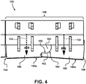
- FIG. 4 is an enlarged front view of one of the support frame members 140 of the scraper blade device 100 shown in FIG. 1 .
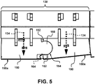
- FIG. 5 is a view similar to FIG. 4 , illustrating another one of the support frame members 140 of the scraper blade device 100 shown in FIG. 1 .
- the swivel interconnection 160 in the illustrated example includes male and female complementary parts.
- the male part is a rounded part that is laterally projecting from one of the blade segments 150.
- the rounded part is secured inside a complementary lateral opening 162 provided on the adjacent blade segment 150, the opening 162 forming the female part.
- This arrangement secures the mating edges 152, 154 of these blade segments 150.
- the various parts are sized so that the maximum tilting angle is generally maintained lower than an angle where adjacent blade segments 150 of two different sets could interfere with one another. Variants are possible as well.
- each swivel interconnection 160 preferably have smooth mating surfaces and it is often desirable to avoid arrangements where grease or other added lubricants are required since they are prone to retain foreign matters such as sand, dirt and de-icing salt. Nevertheless, lubricants may still be used in some implementations.
- FIGS. 4 and 5 the action of the springs 134 pushing the blade segments 150 downwards is schematically depicted by arrows.
- FIGS. 4 and 5 illustrate two examples of relative orientations of the blade segments 150.
- adjacent moldboard sections 138 are configured and disposed so as to provide a marginal spacing 144 between the adjacent ones of their blade segments 150.
- the marginal spacing 144 will prevent the adjacently-disposed blade segments 150 of two different moldboard sections 138 from interfering with one another, at least within at least part of the range of angles.
- the lateral side edges of two adjacent blade segments 150 may engage one another, as depicted in FIG. 5 (lower right corner of the view). This can also be a way to limit the range of angles.
- the scraper blade device 100 can include a reclining capability in order to avoid damages and costly repairs due to an impact with an obstruction.
- An obstruction can be generally defined as something unusual on the roadway surface 104 that cannot be compensated by only sliding one or more of the blade segments 150 thereon. It can be for instance a sudden change in height of the roadway surface 104 or a foreign object. Examples include an abrupt crack in the pavement, a protruding rim of a manhole and an exposed rock, to name just a few. Frozen ice accumulations adhering on the roadway surface 104 can also sometimes create obstructions. An obstruction can be impacted by the scraper blade device 100 if the operator deviated from the desired path.
- curbs can be difficult to locate when they are covered by snow and are often hit during a snow cleaning operation.
- the impact of the scraper blade device 100 with an obstruction is one that can cause damages when the stress due to the impact exceeds a certain limit. Hitting an obstruction can potentially cause a failure and force an operator to immediately stop an ongoing cleaning operation.
- each support frame member 140 is capable of independently pivoting in case of an impact of one of the blade segments 150 with the obstruction and immediately get back in position once the obstruction is cleared. This mitigates the damages to the scraper blade device 100.
- Each of these support frame members 140 is pivotally connected to the upper blade portion 130 and can pivot around a pivot axis 142 ( FIG. 2 ) in case of an impact with an obstruction.
- the pivot axis 142 is substantially parallel to the lowermost edge 100a of the scraper blade device 100. This pivot axis 142 is located at the rear of the front plow surface 122.
- the support frame members 140 are independently pivotable between a forward working position and a tripped position.
- the support frame members 140 are spring loaded toward their forward working position using at least one second bias mechanism 136.
- FIG. 2 shows an example where the second bias mechanism 136 includes an helical spring 136, preferably a plurality thereof, each keeping the corresponding support frame member 140 in its forward wording position. Variants are possible as well.
- the reclining evasive action can be done by pivoting a larger section or even all blade segments 150 backwards together, either by having all support frame members 140 attached together or constructed as a single unit, or by coupling the whole scraper blade device 100 to a pivot provided at the distal end of the frame 108.
- Other designs are possible as well.
- the other support frame members 140 will not be affected and the other blade segment sets 156 can remain in position during the collision. Only the blade segments 150 of the affected blade segment set 156 will recline backwards to pass over the obstruction. The pivot angle will depend on the relative height of the obstruction and the travel speed but as soon as the obstruction is cleared, the support frame member 140 will return back to its normal working position.
- wear indicators 158 provided on the blade segments 150. These wear indicators 158 are in the form of notches machined on a lateral side edge of the blade segments 150. The material at the bottom surface-engaging edge 150a of the blade segments 150 will wear off over time and as a result, the height of the blade segments 150 will become progressively smaller. The bottom surface-engaging edge 150a will eventually be in alignment with the wear indicators 158 and this will inform the operator and/or the mechanics that the blade segments 150 must be replaced by new ones. It should be noted that other wear indicator arrangements are also possible and wear indicators can even be entirely omitted in some implementations.
- FIG. 5 schematically shows a cover plate 164 located near the bottom surface-engaging edge 150a of the blade segments 150.
- This cover plate 164 can be rectangular in shape and is rigidly attached to only one of the two blade segments 150. For instance, one of its ends can be welded or otherwise fastened to the corresponding blade segment 150.
- the cover plate 164 is positioned and disposed to overlap the bottom gap between two adjacent blade segments 150 but since it is only attached to one of the blade segments 150, it will interfere with the tilting movements of the blade segments 150.
- the cover plate 164 closes the bottom gap to minimize the amount of material that can eventually pass therein. It can also be useful to prevent material from accumulating inside the bottom gap under certain conditions and interfere with the normal pivot movements between the blade segments 150 in operation.
- Cover plates such as the one shown at 164 can be provided in front of all other bottom gaps of the scraper blade device 100. Variants in the shape, the disposition and the configuration of the cover plates are possible as well. Cover plates can also be entirely omitted in some implementations.
- FIG. 6 is a front view of another example of a blade segment set 156 with two blade segments 150.
- the shape of the complementary parts of the swivel interconnection 160 and the tolerances were chosen so that the lateral side edges of these adjacent blade segments 150 can tilt with reference to one another over at least a few degrees in both directions. Interestingly, there is no intervening bottom gap between the blade segments 150, regardless of the tilting angle.
- FIGS. 7 to 11 are front views of examples of blade segment sets 156 having more than two blade segments 150.
- FIG. 11 is a top view of the blade segment set 156 shown in FIG. 10 .
- the illustrated blade segment set 156 has three blade segments 150 and the blade segment 150 at the center has to opposite projecting portions to which the blade segments 150 on each side are jointed.
- the mating edges are designed so that the blade segments 150 can tilt of at least a few degrees in each direction. Variants are possible.
- the illustrated blade segment set 156 is somewhat similar to that of FIG. 7 but the complementary parts forming the swivel interconnections 160 on each side of the central blade segment 150 are smaller.
- the shape of the complementary parts of the swivel interconnections 160 and the tolerances are designed so that the lateral side edges of the adjacent blade segments 150 can pivot with reference to one another over at least a few degrees in both directions.
- the illustrated blade segment set 156 includes more than three blade segments 150.
- the multitude of blade segments 150 forms a long chain of interconnected parts.
- This example also shows that in some implementations, the bottom surface-engaging edge 150a of the blade segments 150 can be the shorter side thereof. Nevertheless, one can also design a blade segment set 156 having a multitude of interconnected blade segments 150 where the bottom surface-engaging edge 150a is the longer side thereof.
- the scraper blade device 100 can include only one blade segment set 156 in some implementations. Such scraper blade device 100 could then be made of a multitude of interconnected blade segments 150, as shown for instance in FIG. 9 . Having all blade segments 150 interconnected can be highly desirable for scraper blade devices 100 that are used laterally on a snowplow.
- a laterally-disposed scraper blade device is often used in addition to a front scraper blade device on a vehicle designed for cleaning snow on a highway or the like. In operation, a laterally-disposed scraper blade device is often not perpendicular to the forward travel direction. It is rather set on the roadway surface 104 at a steep angle with reference to the forward travel direction 120, for instance at an angle of 45° or more.
- the bottom surface-engaging edges 150a of the blade segments 150 slide on the roadway surface 104 obliquely and prevents a discontinuity in the wavy pattern formed by the juxtaposed bottom surface-engaging edges 150a so as to ensure a smoother operation.
- the example shown in FIG. 3 would be a lateral scraper blade device 100 provided on the left side of a vehicle whose forward travel direction corresponds to the left-hand side of FIG. 3 , one can see that the abrupt discontinuity along the lowermost edge 100a of scraper blade device 100 between the first two moldboard sections 138 and also the one between the last two moldboard sections 138 are not desirable since they can interfere with the motion of the scraper blade device 100.
- the blade segments 150 have ends overlapping one another where the swivel interconnections 160 are provided.
- the blade segments 150 are not all coplanar but in this example, they nevertheless remain parallel to one another regardless of the tilting angle.
- the swivel interconnections 160 includes rods for jointing the adjacent blade segments 150, as best shown in FIG. 11 .
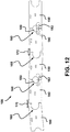
- FIG. 12 is a front view of another example of a blade segment set 156. Only some of the blade segments 150 of this set is shown. This figure also shows that one can provide elastic means over some of the adjacent blade segments 150 to urge them closer to one another. Two examples are shown, one where the elastic means linking the upper parts of two adjacent blade segments 150 includes an helical tension spring 170 and one where the elastic means linking the upper parts of two adjacent blade segments 150 includes an elastic rod 172, such as one made of a urethane material or the like. Other kinds of elastic means are possible as well. One can provide elastic means 170, 172 between all adjacent blade segments 150 and/or use the same kind of elastic means everywhere.
- FIG. 12 further shows that some of the swivel interconnections 160 include a disc 180 located between the lateral side edges of corresponding blade segments 150.
- Holding plates 182 are all provided on both sides (front and rear) to keep the disc 180 in position.
- the holding plates 182 are each attached to only one of the adjacent blade segments 150.
- the guiding arrangement for the blade segments 150 keep them in position so in this case.
- the swivel interconnections 160 with the discs 180 cannot resist lateral detachment but this kind of swivel interconnection is simpler to manufacture and may be suitable for some implementations.
- wing plates or extensions when wing plates or extensions are used, one can provide blade segments 150 in accordance with the proposed concept on at least one of the wing plates or extensions, or even both.
- Each wing plate or extension in such context, can be considered as a distinct scraper blade device 100, even when they are mounted on a larger one that already incorporates the proposed concept.
- the proposed concept provides a way to further increase the efficiency of the cleaning compared to existing designs. This yields several advantages, including for instance reducing the amount of de-icing chemicals, increasing road safety, etc.
- the proposed concept can also provide other advantages, including: an improved mechanical strength, a facilitated maintenance in case of a failure of a part, the possibility of using the scraper blade device even in case of a partial failure, an increased travel speed while in use, an increased overall fuel efficiency, a reduction of the damages and wear to the roadway surfaces, a reduction of the amounts of de-icing chemicals released in the environment and a maintenance cost reduction for the operators.
- the scraper blade device 100 can be made using a manufacturing process that includes any one of the following acts or combinations thereof: cutting, bending, punching, welding, bolting, gluing, painting.
Landscapes
- Engineering & Computer Science (AREA)
- Architecture (AREA)
- Civil Engineering (AREA)
- Structural Engineering (AREA)
- Cleaning In General (AREA)
Claims (14)
- Un dispositif à lame de grattage (100) pour nettoyer une surface de chaussée (104), le dispositif à lame de grattage (100) ayant une surface frontale de grattage (122) et un bord situé le plus bas (100a), le dispositif à lame de grattage (100) comprenant :une portion de lame supérieure (130) définissant généralement une zone supérieure de la surface frontale de grattage (122) du dispositif à lame de grattage (100); etune portion de lame inférieure (132) définissant généralement une zone inférieure de la surface frontale de grattage (122) du dispositif à lame de grattage (100), la portion de lame inférieure (132) comprenant une pluralité de segments de lame (150) juxtaposés et qui sont disposés dans le sens de la largeur, chaque segment de lame (150) comprenant un bord inférieur de contact de surface (150a) et les bords inférieurs de contact de surface (150a) des segments de lame (150) formant collectivement le bord situé le plus bas (100a) du dispositif à lame de grattage (100),chaque segment de lame (150) étant mobile de manière coulissante selon un mouvement en va et vient par rapport à la portion de lame supérieure (130), les segments de lame (150) de la portion de lame inférieure (132) formant un ou plusieurs ensembles de segments de lame (156);caractérisé en ce que :chaque ensemble de segments de lame (156) comporte au moins deux des segments de lame (150) qui sont articulés de manière pivotante à une interconnexion pivotante correspondante (160),selon lequel, en fonctionnement, les bords inférieurs de contact de surface (150a) des segments de lame (150) d'un même ensemble de segments de lame (156) peuvent basculer l'un par rapport à l'autre lorsqu'ils suivent des variations de profil de la surface de la chaussée (104),dans lequel chaque segment de lame (150) est fixé de manière coulissante à un élément de bâti de support correspondant (140), etdans lequel chaque élément de bâti de support (140) est fixé de manière pivotante à la portion de lame supérieure (130) et peut pivoter autour d'un axe de pivotement (142) qui est sensiblement parallèle au bord situé le plus bas (100a) du dispositif à lame de grattage (100), chaque élément de bâti de support (140) étant sollicité vers une position avant de travail par au moins un second mécanisme de rappel (136).
- Le dispositif à lame de grattage (100) selon la revendication 1, dans lequel l'interconnexion pivotante (160) comprend des parties complémentaires mâle et femelle situées sur les bords latéraux correspondants des segments de lame (150).
- Le dispositif à lame de grattage (100) selon la revendication 1, dans lequel l'interconnexion pivotante (160) comprend un accouplement à goupille chevauchant les extrémités de deux segments de lame adjacents parmi les segments de lame (150).
- Le dispositif à lame de grattage (100) selon l'une quelconque des revendications 1 à 3, dans lequel l'ensemble de segments de lame (156), ou au moins l'un des ensembles de segments de lame (156), comprend plus de deux segments de lame (150) interconnectés parmi les segments de lame (150).
- Le dispositif à lame de grattage (100) selon l'une quelconque des revendications 1 à 4, dans lequel les segments de lame (150) d'un même ensemble de segments de lame (156) sont parallèles les uns aux autres, de préférence coplanaires les uns par rapport aux autres.
- Le dispositif à lame de grattage (100) selon l'une quelconque des revendications 1 à 5, dans lequel chaque segment de lame (150) est mobile entre une position étendue vers le bas et une position rétractée vers le haut, les segments de lame (150) étant sollicités vers le bas par une pluralité de premiers mécanismes de rappel (134).
- Le dispositif à lame de grattage (100) selon la revendication 6, dans lequel chaque premier mécanisme de rappel (134) comprend un ressort hélicoïdal ayant une extrémité fixée à l'un des segments de lame (150) correspondant.
- Le dispositif à lame de grattage (100) selon la revendication 6 ou 7, dans lequel chaque premier mécanisme de rappel (134) est associé à un seul des segments de lame (150).
- Le dispositif à lame de grattage (100) selon la revendication 1, dans lequel les ensembles de segments de lame (156) et les éléments de bâti de support (140) sont en nombres égaux.
- Le dispositif à lame de grattage (100) selon l'une des revendications précédentes, dans lequel chaque second mécanisme de rappel (136) est associé à un seul des éléments de bâti de support (140).
- Le dispositif à lame de grattage (100) selon l'une des revendications précédentes, dans lequel le au moins un second mécanisme de rappel (136) comprend un ressort hélicoïdal ayant une première extrémité attachée à l'élément de bâti de support correspondant (140) et une seconde extrémité attachée à la portion de lame supérieure (130).
- Le dispositif à lame de grattage (100) selon l'une des revendications précédentes, dans lequel au moins l'un des éléments de bâti de support (140) peut être déplacé indépendamment par rapport à un autre des éléments de bâti de support (140).
- Le dispositif à lame de grattage (100) selon l'une quelconque des revendications précédentes, dans lequel le dispositif à lame de grattage (100) comprend une pluralité de sections de pelle juxtaposées (138) qui sont fixées collectivement pour former une unité, chaque section de pelle (138) comprenant une partie de la portion de lame supérieure (130) et une partie de la portion de lame inférieure (132), la partie de la portion de lame inférieure (132) comprenant l'un des ensembles de segments de lame (156) et l'un des éléments de bâti de support (140) correspondant.
- Le dispositif à lame de grattage (100) selon l'une quelconque des revendications 1 à 13, dans lequel le dispositif à lame de grattage (100) comprend au moins l'une des caractéristiques suivantes :il y a plus de deux ensembles de segments de lame (156), chaque ensemble de segments de lame (156) ayant un espacement marginal (144) entre les segments de lame (150) adjacents;le dispositif à lame de grattage (100) comprend en outre des moyens élastiques (170, 172) s'étendant entre au moins deux des segments de lame (150) du dispositif à lame de grattage (100);le dispositif à lame de grattage (100) comprend en outre une plaque de recouvrement (164) s'étendant devant un interstice inférieur entre deux segments adjacents parmi les segments de lame (150) du dispositif à lame de grattage (100), la plaque de recouvrement (164) étant fixée à l'un des deux segments de lame (150) adjacents;le dispositif à lame de grattage (100) est monté sur un côté d'un véhicule (102) et le bord situé le plus bas (100a) vient en contact avec la surface de la chaussée (104) à un angle escarpé par rapport à une direction de déplacement vers l'avant (120);le dispositif à lame de grattage (100) est monté sur une aile latérale ou une extension.
Priority Applications (1)
| Application Number | Priority Date | Filing Date | Title |
|---|---|---|---|
| PL15851592T PL3207183T3 (pl) | 2014-10-17 | 2015-10-16 | Urządzenie lemiesza zgarniającego z umieszczonymi w rzędzie segmentami lemiesza ze wzajemnym połączeniem obrotowym między krawędziami współpracującymi |
Applications Claiming Priority (2)
| Application Number | Priority Date | Filing Date | Title |
|---|---|---|---|
| CA2867957A CA2867957A1 (fr) | 2014-10-17 | 2014-10-17 | Segments de lames juxtaposees de dispositif racleur comportant un raccord pivotant entre les rebords d'accouplement |
| PCT/CA2015/051045 WO2016058106A1 (fr) | 2014-10-17 | 2015-10-16 | Dispositif de lame racleuse à segments de lame juxtaposés présentant un raccordement à pivot entre bords de contact |
Publications (3)
| Publication Number | Publication Date |
|---|---|
| EP3207183A1 EP3207183A1 (fr) | 2017-08-23 |
| EP3207183A4 EP3207183A4 (fr) | 2017-10-11 |
| EP3207183B1 true EP3207183B1 (fr) | 2020-09-16 |
Family
ID=55745929
Family Applications (1)
| Application Number | Title | Priority Date | Filing Date |
|---|---|---|---|
| EP15851592.4A Active EP3207183B1 (fr) | 2014-10-17 | 2015-10-16 | Dispositif de lame racleuse à segments de lame juxtaposés présentant un raccordement à pivot entre bords de contact |
Country Status (6)
| Country | Link |
|---|---|
| US (2) | US10480140B2 (fr) |
| EP (1) | EP3207183B1 (fr) |
| CA (2) | CA2867957A1 (fr) |
| DK (1) | DK3207183T3 (fr) |
| PL (1) | PL3207183T3 (fr) |
| WO (1) | WO2016058106A1 (fr) |
Families Citing this family (18)
| Publication number | Priority date | Publication date | Assignee | Title |
|---|---|---|---|---|
| CA2867957A1 (fr) | 2014-10-17 | 2016-04-17 | Jimmy Vigneault | Segments de lames juxtaposees de dispositif racleur comportant un raccord pivotant entre les rebords d'accouplement |
| PL3408454T3 (pl) * | 2016-01-26 | 2024-05-13 | Usinage Pro24 Inc. | Urządzenie lemiesza zgarniającego z regulowanymi lemieszami |
| DK3565928T3 (da) * | 2017-01-05 | 2021-09-06 | 9407 4895 Quebec Inc | Skrabeindretning til rydning af en vejbaneoverflade |
| US10781570B2 (en) * | 2017-03-13 | 2020-09-22 | Ag Focus Llc | Retrofit cylinder assembly for agricultural equipment |
| US10865533B2 (en) | 2017-05-12 | 2020-12-15 | Michael F. Stephan | Flexible snowplow cutting edge |
| US11124935B2 (en) | 2017-11-07 | 2021-09-21 | 1708828 Ontario Limited | Snowplow with ground contour following cutting edge and impact absorption |
| US10865534B2 (en) | 2017-11-07 | 2020-12-15 | 1708828 Ontario Limited | Snowplow with ground contour following cutting edge and impact absorption |
| WO2020087179A1 (fr) * | 2018-10-31 | 2020-05-07 | Duchesneau Paul | Chasse-neige comprenant une lame de coupe à angle de coupe positif et grattoir à glace |
| AT522692B1 (de) * | 2019-10-03 | 2021-01-15 | Reiter Kommunaltechnik Gmbh | Schürfleistenanordnung zur Befestigung an einem Pflugschild |
| WO2021087612A1 (fr) * | 2019-11-05 | 2021-05-14 | 9407-4895 Québec Inc. | Dispositif de lame racleuse réglable en largeur |
| CA3100750A1 (en) * | 2019-11-26 | 2021-05-26 | 9251-7747 Quebec Inc. | Ice removal blade assembly for a vehicle |
| US11248354B2 (en) * | 2020-03-12 | 2022-02-15 | Ricky A. Weihl | Plow assembly |
| US11466417B2 (en) * | 2020-03-12 | 2022-10-11 | Ricky A. Weihl | Plow assembly |
| AT523738B8 (de) * | 2021-01-12 | 2022-02-15 | Reiter Kommunaltechnik Gmbh | Schürfleistenanordnung und Schürfleistenkassette |
| US12571175B2 (en) * | 2021-08-30 | 2026-03-10 | 1708828 Ontario Ltd. | Cutting edge systems for snowplow moldboards |
| CA3141241A1 (fr) | 2021-12-03 | 2023-06-03 | Ariens Company | Appareil pour un vehicule a direction a glissement |
| CH719686A1 (de) * | 2022-05-10 | 2023-11-15 | Zaugg Ag Eggiwil | Klappschar für ein Räumgerät mit einem Räumschild. |
| US12497744B2 (en) * | 2022-06-14 | 2025-12-16 | Douglas Dynamics, L.L.C. | Containment plow |
Family Cites Families (109)
| Publication number | Priority date | Publication date | Assignee | Title |
|---|---|---|---|---|
| US520479A (en) | 1894-05-29 | btjnnell | ||
| US1383409A (en) | 1918-09-23 | 1921-07-05 | Baker Mfg Co | Snowplow |
| US1609353A (en) | 1925-08-22 | 1926-12-07 | Wyatt J Heflin | Shock absorber |
| GB402584A (en) | 1932-10-25 | 1933-12-07 | William John Bunce | Improvements in or relating to snow clearing devices for attachment to road vehicles |
| US2055291A (en) | 1935-08-12 | 1936-09-22 | Maine Steel Products Company | Material moving apparatus |
| US2116351A (en) | 1936-09-11 | 1938-05-03 | Nat Fireworks Inc | Snow plow |
| US2337434A (en) | 1941-10-18 | 1943-12-21 | Baker Mfg Co | Snowplow |
| US2615707A (en) | 1948-10-13 | 1952-10-28 | Bouligny Inc R H | Cushioning means |
| US2723630A (en) * | 1950-02-08 | 1955-11-15 | Buckeye Steel Castings Co | Damping device for railway car trucks |
| FR1050311A (fr) | 1950-08-04 | 1954-01-06 | Chasse-neige | |
| US2697289A (en) | 1951-04-06 | 1954-12-21 | Burch Corp | Trip blade snowplow |
| US2650088A (en) | 1951-05-29 | 1953-08-25 | Formanek Alois | Double-acting shock absorber and stabilizer |
| GB766042A (en) | 1951-08-23 | 1957-01-16 | Ferguson Harry Inc | Improvements in or relating to earth-working implements for use with tractors |
| US2775830A (en) | 1951-08-28 | 1957-01-01 | Frink Sno Plows Inc | Reversible trip blade snow plow |
| CH313333A (de) | 1952-11-10 | 1956-04-15 | Kurt Dipl Ing Gasser | Schneepflug mit durchschlagbarer und ausweichbarer Pflugschar |
| US2962821A (en) | 1958-11-03 | 1960-12-06 | Peitl Josef | Snow plow |
| US3014289A (en) | 1959-01-15 | 1961-12-26 | Anthony J Torrey | Snow plow |
| CH382207A (de) | 1960-08-31 | 1964-09-30 | Baltensperger Eduard | Schneepflug |
| DE1179975B (de) | 1962-03-10 | 1964-10-22 | Dr Gottfried Reissinger | Raeumschar fuer Schneepfluege mit an der Raeumschar angelenkter Raeumleiste |
| US3231991A (en) | 1963-05-31 | 1966-02-01 | Wandscheer Evert | Snow ridge scraper |
| FR1406341A (fr) | 1963-09-04 | 1965-07-16 | Engin de nivellement | |
| CH416708A (de) | 1964-03-10 | 1966-07-15 | Baltensperger Eduard | Schneepflug |
| US3400475A (en) | 1965-05-28 | 1968-09-10 | Meyer Products Inc | Snow plow |
| US3465456A (en) | 1966-11-18 | 1969-09-09 | Meyer Products Inc | Blade for snowplows and similar devices |
| US3503601A (en) | 1967-10-20 | 1970-03-31 | Associated Spring Corp | Axial springs loaded in parallel |
| US3547203A (en) | 1967-11-01 | 1970-12-15 | Monarch Road Machinery Co | Back blade assembly and control therefor |
| US3650498A (en) | 1969-05-02 | 1972-03-21 | Bell Telephone Labor Inc | Adjustable spring suspension mount having constant static deflection |
| DE1929177C3 (de) | 1969-06-09 | 1978-04-20 | Reissinger, Gottfried, Dr., 8124 St Heinrich | Straßenräumgerät |
| US3772803A (en) | 1972-04-03 | 1973-11-20 | L Cote | Snow plow |
| AT313966B (de) | 1972-04-11 | 1974-03-11 | Peitl Gmbh J | Schneepflug |
| DE2421713B1 (de) | 1974-05-04 | 1975-10-30 | Ing. Alfred Schmidt Gmbh, 7822 St Blasien | Schneepflug |
| US4079926A (en) | 1976-01-05 | 1978-03-21 | Brunswick Corporation | Energy absorbing support |
| CH600058A5 (fr) | 1976-04-28 | 1978-06-15 | Schmidt Alfred Ing Gmbh | |
| US4031966A (en) | 1976-06-21 | 1977-06-28 | Frink Sno-Plows | Operating and shock cylinder assembly for vehicle underbody scrapers and the like |
| US4249323A (en) | 1978-06-19 | 1981-02-10 | De Lorean Manufacturing Company | Variable wing plow blade and mounting structure therefor |
| JPS591855B2 (ja) | 1978-10-31 | 1984-01-14 | ティー・シー・エム株式会社 | 分割ブレ−ド装置 |
| CA1130556A (fr) | 1978-12-08 | 1982-08-31 | Harro Reissinger | Dispositif de degagement des voies carrossables |
| CH638007A5 (en) | 1979-02-07 | 1983-08-31 | Boschung Marcel Ag | Single-side snow plough |
| US4681303A (en) | 1983-03-07 | 1987-07-21 | Grassano Vincent R | Shock-absorbent connector |
| US4529080A (en) | 1983-08-19 | 1985-07-16 | Chrysler Corporation | Bi-directional spring loaded shift fork assembly |
| US4570366A (en) | 1984-08-10 | 1986-02-18 | Yost Kenneth J | Snowplow and blade having triangular rotatable cutting block teeth |
| US4597202A (en) | 1984-11-21 | 1986-07-01 | Root Spring Scraper Company | V-shaped highway snow plows |
| US4669205A (en) | 1986-01-24 | 1987-06-02 | Smathers James A | Segmented snow plow apparatus |
| DE3608893C2 (de) | 1986-03-17 | 1997-12-18 | Ernst Probst Fa | Planiereinrichtung |
| DE3711988A1 (de) | 1987-03-27 | 1988-10-20 | Peter Escher | Schneepflug |
| DE8811708U1 (de) | 1988-09-15 | 1989-05-03 | ESCHER Geräte und Maschinen-Vertriebsgesellschaft mbH, 8530 Neustadt | Räumschild für einen Schneepflug |
| CH678344A5 (en) | 1989-05-30 | 1991-08-30 | Peter Ag Konrad | Snow plough with share inclined to travel direction - has longitudinal slider on share, with dished profile open in forward travel direction |
| US5140763A (en) * | 1991-02-11 | 1992-08-25 | Nichols Iv Charles W | Snow removal apparatus |
| FR2677929A1 (fr) | 1991-06-24 | 1992-12-24 | Bianchi Mauro Sa | Procede de suspension pour vehicules utilisant deux raideurs, destinees respectivement a l'obtention d'un bon niveau de confort et d'un bon niveau de comportement. |
| US5191729A (en) | 1991-09-30 | 1993-03-09 | Frink America, Inc. | Trip apparatus for moldboard assembly |
| FI679U1 (fi) | 1993-01-22 | 1993-04-23 | Pertti Vauhkonen | Bett foer en plog |
| US5344254A (en) | 1993-04-14 | 1994-09-06 | Blaw-Knox Construction Equipment Corporation | Pivoting screed edger |
| DE4441654C2 (de) | 1993-12-20 | 1996-02-08 | Theo Haering | Schneepflug |
| US5437113A (en) | 1994-01-12 | 1995-08-01 | Jones; Daniel K. | Snow plow trip cutting edge |
| US5697172A (en) | 1995-06-14 | 1997-12-16 | Schmidt Engineering & Equipment, Inc. | Trip edge snowplow |
| US5720122A (en) | 1996-04-29 | 1998-02-24 | Mclellan; Jeffrey S. | Plow blade with adjustable scraping bar |
| US5899007A (en) | 1996-06-07 | 1999-05-04 | Blizzard Corporation | Adjustable wing plow |
| CA2208130C (fr) | 1996-06-20 | 2003-03-18 | Denis Desmarais | Pelle a neige avec panneaux lateraux ajustables |
| DE29622102U1 (de) | 1996-12-19 | 1997-02-20 | Maier, Walter, 84478 Waldkraiburg | Befestigungsvorrichtung für Schürfleisten an der Pflugschar eines Schneeräumfahrzeuges |
| US5921010A (en) | 1997-02-12 | 1999-07-13 | Little Falls Machine, Inc. | Flow blade operating system |
| US5819443A (en) * | 1997-07-25 | 1998-10-13 | Winter; William L. | Snow removal apparatus |
| US6073371A (en) | 1997-12-22 | 2000-06-13 | Henderson Manufacturing Company | Snowplow assembly with adjustable-bias trip mechanism |
| US6035944A (en) | 1998-05-27 | 2000-03-14 | M. J. Electric, Inc. | Hinged plow attachment for wheeled and tracked vehicles |
| US6345583B1 (en) | 2000-07-11 | 2002-02-12 | Willie L. Thackston | Bi-directional dampening device and method therefor |
| AT412003B (de) | 2001-04-02 | 2004-08-26 | Anton Kahlbacher | Schneepflug mit einer aus mehreren scharsegmenten bestehenden pflugschar |
| US6895698B2 (en) | 2001-09-07 | 2005-05-24 | Henderson Manufacturing Company | Plow assembly with adjustable trip mechanism |
| TW589276B (en) | 2001-10-09 | 2004-06-01 | Martin Eng Co | Conveyor belt cleaner including a scraper blade mounting apparatus having a biasing member |
| US7681335B2 (en) | 2001-11-12 | 2010-03-23 | Agri-Cover, Inc. | Snow plow having attachable biasing member |
| US6817118B2 (en) | 2001-11-12 | 2004-11-16 | Charles M. Schmeichel | Self-adjusting snow plow |
| US6823615B2 (en) | 2002-01-28 | 2004-11-30 | Randy W. Strait | Sectional snow plow |
| US6892480B1 (en) | 2002-02-07 | 2005-05-17 | The Gledhill Road Machinery Company, Inc. | Load reliever for plow moldboard |
| US6751894B2 (en) | 2002-05-30 | 2004-06-22 | Schmidt Engineering And Equipment, Inc. | Snow removal apparatus and method of removing snow |
| US6701646B2 (en) | 2002-07-10 | 2004-03-09 | Sno-Way International, Inc. | Spring bracket design and method for snow plow blade tripping mechanism |
| US6618965B1 (en) | 2002-07-10 | 2003-09-16 | Sno-Way International, Inc. | Cushion stop and method for absorbing bidirectional impact of snow plow blade tripping |
| CA2423830C (fr) | 2003-03-31 | 2004-02-10 | Guy Hamel | Systeme articule de lame niveleuse |
| US7134227B2 (en) | 2003-05-02 | 2006-11-14 | Douglas Dynamics, L.L.C. | Adjustable wing plow |
| US7658022B2 (en) | 2003-07-07 | 2010-02-09 | Arctic Snow and Ice Control, Inc. | Slip hitch for a snow plow |
| JP4077776B2 (ja) | 2003-08-27 | 2008-04-23 | 株式会社協和機械製作所 | 排雪用シャッタ装置 |
| US7100311B2 (en) | 2004-05-07 | 2006-09-05 | Schmidt Engineering And Equipment, Inc. | Gate assembly and method for a snow plow blade |
| US7100314B1 (en) | 2004-06-05 | 2006-09-05 | Jensen Leland E | Plow blade float attachment |
| US7171770B2 (en) | 2004-08-25 | 2007-02-06 | Sno-Way International, Inc. | Trip edge snow plow blade |
| US7350774B2 (en) | 2004-09-07 | 2008-04-01 | Danly Iem, Llc | Long travel, high force combination spring |
| US7467485B2 (en) | 2004-09-28 | 2008-12-23 | Guy Hamel | Inserted knife fortified snowplow blade |
| CN2903176Y (zh) | 2006-03-17 | 2007-05-23 | 陈震 | 清雪机越障式前铲 |
| KR200422656Y1 (ko) | 2006-04-11 | 2006-07-31 | 대진특장 주식회사 | 연장식 제설판을 구비하는 제설기 |
| US7730643B2 (en) | 2006-05-23 | 2010-06-08 | Cives Corporation | Two-stage snow plow |
| US7555853B2 (en) | 2006-11-17 | 2009-07-07 | Adepco Technologies Corp. | Snow plow assembly with resilient snow plow blade mounting structure |
| US8776405B2 (en) | 2006-11-17 | 2014-07-15 | Adepco Technologies, Corp. | Snow plow for adjusting to surface contours and obstacles |
| US7493710B2 (en) | 2007-03-15 | 2009-02-24 | 1708828 Ontario Inc. | Snowplow with pivoting sideblades |
| US7743536B2 (en) | 2007-03-29 | 2010-06-29 | Degelman Industries Ltd. | Hinged plow and scraper blade |
| US7543401B2 (en) | 2007-08-17 | 2009-06-09 | Doug Hughes | Back drag plow |
| US7631441B2 (en) | 2008-03-10 | 2009-12-15 | Valley Blades Limited | Wearing edge attachment system |
| US7841109B2 (en) | 2008-06-17 | 2010-11-30 | Sno-Way International, Inc. | Plow including independently moveable wings |
| FI121124B (fi) | 2008-08-05 | 2010-07-15 | Destia Oy | Alusterä |
| ITBO20080505A1 (it) | 2008-08-05 | 2010-02-06 | Studio Tecnico Piazzi Di Piazzi Geo Metra Roberto | Dispositivo per il sollevamento della neve dalle pavimentazioni stradali |
| CA2698744A1 (fr) * | 2010-04-06 | 2011-10-06 | Jimmy Vigneault | Dispositif de grattage d'une matiere indesirable sur une surface procede de fabrication du dispositif utilisation du dispositif |
| CN201866149U (zh) | 2010-11-03 | 2011-06-15 | 中集车辆(集团)有限公司 | 弹簧装置及具有该弹簧装置的雪铲 |
| CA2723630C (fr) * | 2010-12-03 | 2017-04-04 | Equipement Dhp Inc. | Chasse-neige |
| US20130174452A1 (en) * | 2012-01-06 | 2013-07-11 | Kennametal Inc. | Plow Blade Assembly |
| US9051700B2 (en) | 2012-03-06 | 2015-06-09 | The Toro Company | V-blade snowplow having dual trip mechanism |
| JP6004904B2 (ja) | 2012-11-12 | 2016-10-12 | 株式会社ササキコーポレーション | 歩行型ブレード除雪機 |
| US9200418B2 (en) | 2013-02-26 | 2015-12-01 | Douglas Dynamics, L.L.C. | Method and apparatus for installing cutting edges on V-blade plow |
| CN203346934U (zh) | 2013-06-26 | 2013-12-18 | 湖南三一路面机械有限公司 | 铲刀作业装置和平地机 |
| CN103498444A (zh) | 2013-09-23 | 2014-01-08 | 王启顺 | 一种前后越障抗磨除雪铲及其制备方法 |
| US20150101216A1 (en) | 2013-10-16 | 2015-04-16 | Ronald W. Kerr | Plow mechanism spring assembly |
| CA2867957A1 (fr) | 2014-10-17 | 2016-04-17 | Jimmy Vigneault | Segments de lames juxtaposees de dispositif racleur comportant un raccord pivotant entre les rebords d'accouplement |
| CN205100150U (zh) | 2015-11-15 | 2016-03-23 | 王锡山 | 一种铲刃越障后翻转双轴转动补偿铲体平衡除雪铲 |
| CN205387727U (zh) | 2016-03-07 | 2016-07-20 | 北京创通建设集团有限公司 | 一种平地机 |
| DK3565928T3 (da) | 2017-01-05 | 2021-09-06 | 9407 4895 Quebec Inc | Skrabeindretning til rydning af en vejbaneoverflade |
-
2014
- 2014-10-17 CA CA2867957A patent/CA2867957A1/fr not_active Abandoned
-
2015
- 2015-10-16 WO PCT/CA2015/051045 patent/WO2016058106A1/fr not_active Ceased
- 2015-10-16 DK DK15851592.4T patent/DK3207183T3/da active
- 2015-10-16 PL PL15851592T patent/PL3207183T3/pl unknown
- 2015-10-16 CA CA2964414A patent/CA2964414C/fr active Active
- 2015-10-16 EP EP15851592.4A patent/EP3207183B1/fr active Active
-
2017
- 2017-04-12 US US15/486,275 patent/US10480140B2/en active Active
-
2019
- 2019-09-23 US US16/579,364 patent/US11131071B2/en active Active
Non-Patent Citations (1)
| Title |
|---|
| None * |
Also Published As
| Publication number | Publication date |
|---|---|
| DK3207183T3 (da) | 2020-12-14 |
| US20170218585A1 (en) | 2017-08-03 |
| US20200018030A1 (en) | 2020-01-16 |
| US10480140B2 (en) | 2019-11-19 |
| WO2016058106A1 (fr) | 2016-04-21 |
| EP3207183A4 (fr) | 2017-10-11 |
| PL3207183T3 (pl) | 2021-05-04 |
| US11131071B2 (en) | 2021-09-28 |
| CA2964414C (fr) | 2023-08-22 |
| EP3207183A1 (fr) | 2017-08-23 |
| CA2964414A1 (fr) | 2016-04-21 |
| CA2867957A1 (fr) | 2016-04-17 |
Similar Documents
| Publication | Publication Date | Title |
|---|---|---|
| US11131071B2 (en) | Scraper blade device with juxtaposed blade segments having a swivel interconnection between mating edges | |
| US9611604B2 (en) | Scraper blade device for cleaning a surface and method | |
| US20220243411A1 (en) | Width-adjustable scraper blade device | |
| EP3565928B1 (fr) | Dispositif de raclage pour déblayer une surface de chaussée | |
| US7975408B2 (en) | Snow plow and method of plowing snow | |
| CA2766435C (fr) | Chasse-neige gratteur avec rallonge | |
| US11668060B2 (en) | Material pusher with floating coupler | |
| CN114575299B (zh) | 无动力越障除雪车 | |
| CN102619185A (zh) | 一种具较好破冰清雪功能的可越障破冰铲 |
Legal Events
| Date | Code | Title | Description |
|---|---|---|---|
| STAA | Information on the status of an ep patent application or granted ep patent |
Free format text: STATUS: THE INTERNATIONAL PUBLICATION HAS BEEN MADE |
|
| PUAI | Public reference made under article 153(3) epc to a published international application that has entered the european phase |
Free format text: ORIGINAL CODE: 0009012 |
|
| STAA | Information on the status of an ep patent application or granted ep patent |
Free format text: STATUS: REQUEST FOR EXAMINATION WAS MADE |
|
| 17P | Request for examination filed |
Effective date: 20170512 |
|
| AK | Designated contracting states |
Kind code of ref document: A1 Designated state(s): AL AT BE BG CH CY CZ DE DK EE ES FI FR GB GR HR HU IE IS IT LI LT LU LV MC MK MT NL NO PL PT RO RS SE SI SK SM TR |
|
| AX | Request for extension of the european patent |
Extension state: BA ME |
|
| A4 | Supplementary search report drawn up and despatched |
Effective date: 20170908 |
|
| RIC1 | Information provided on ipc code assigned before grant |
Ipc: E01H 5/06 20060101AFI20170904BHEP |
|
| DAV | Request for validation of the european patent (deleted) | ||
| DAX | Request for extension of the european patent (deleted) | ||
| STAA | Information on the status of an ep patent application or granted ep patent |
Free format text: STATUS: EXAMINATION IS IN PROGRESS |
|
| 17Q | First examination report despatched |
Effective date: 20180704 |
|
| GRAP | Despatch of communication of intention to grant a patent |
Free format text: ORIGINAL CODE: EPIDOSNIGR1 |
|
| STAA | Information on the status of an ep patent application or granted ep patent |
Free format text: STATUS: GRANT OF PATENT IS INTENDED |
|
| INTG | Intention to grant announced |
Effective date: 20200407 |
|
| RAP1 | Party data changed (applicant data changed or rights of an application transferred) |
Owner name: 9407-4895 QUEBEC INC. |
|
| RIN1 | Information on inventor provided before grant (corrected) |
Inventor name: VIGNEAULT, JIMMY |
|
| GRAS | Grant fee paid |
Free format text: ORIGINAL CODE: EPIDOSNIGR3 |
|
| GRAA | (expected) grant |
Free format text: ORIGINAL CODE: 0009210 |
|
| STAA | Information on the status of an ep patent application or granted ep patent |
Free format text: STATUS: THE PATENT HAS BEEN GRANTED |
|
| AK | Designated contracting states |
Kind code of ref document: B1 Designated state(s): AL AT BE BG CH CY CZ DE DK EE ES FI FR GB GR HR HU IE IS IT LI LT LU LV MC MK MT NL NO PL PT RO RS SE SI SK SM TR |
|
| REG | Reference to a national code |
Ref country code: GB Ref legal event code: FG4D |
|
| REG | Reference to a national code |
Ref country code: CH Ref legal event code: EP |
|
| REG | Reference to a national code |
Ref country code: DE Ref legal event code: R096 Ref document number: 602015059307 Country of ref document: DE |
|
| REG | Reference to a national code |
Ref country code: IE Ref legal event code: FG4D |
|
| REG | Reference to a national code |
Ref country code: AT Ref legal event code: REF Ref document number: 1314282 Country of ref document: AT Kind code of ref document: T Effective date: 20201015 |
|
| REG | Reference to a national code |
Ref country code: DK Ref legal event code: T3 Effective date: 20201209 |
|
| REG | Reference to a national code |
Ref country code: CH Ref legal event code: NV Representative=s name: STOLMAR AND PARTNER INTELLECTUAL PROPERTY S.A., CH |
|
| REG | Reference to a national code |
Ref country code: FI Ref legal event code: FGE |
|
| REG | Reference to a national code |
Ref country code: DE Ref legal event code: R082 Ref document number: 602015059307 Country of ref document: DE Representative=s name: STOLMAR & PARTNER PATENTANWAELTE PARTG MBB, DE Ref country code: DE Ref legal event code: R081 Ref document number: 602015059307 Country of ref document: DE Owner name: 9407-4895 QUEBEC INC., PLESSISVILLE, CA Free format text: FORMER OWNER: 9407-4895 QUEBEC INC., PLESSIVILLE, QC, CA |
|
| PG25 | Lapsed in a contracting state [announced via postgrant information from national office to epo] |
Ref country code: BG Free format text: LAPSE BECAUSE OF FAILURE TO SUBMIT A TRANSLATION OF THE DESCRIPTION OR TO PAY THE FEE WITHIN THE PRESCRIBED TIME-LIMIT Effective date: 20201216 Ref country code: GR Free format text: LAPSE BECAUSE OF FAILURE TO SUBMIT A TRANSLATION OF THE DESCRIPTION OR TO PAY THE FEE WITHIN THE PRESCRIBED TIME-LIMIT Effective date: 20201217 Ref country code: HR Free format text: LAPSE BECAUSE OF FAILURE TO SUBMIT A TRANSLATION OF THE DESCRIPTION OR TO PAY THE FEE WITHIN THE PRESCRIBED TIME-LIMIT Effective date: 20200916 |
|
| REG | Reference to a national code |
Ref country code: CH Ref legal event code: PK Free format text: BERICHTIGUNG INHABER |
|
| REG | Reference to a national code |
Ref country code: NO Ref legal event code: T2 Effective date: 20200916 |
|
| REG | Reference to a national code |
Ref country code: NL Ref legal event code: MP Effective date: 20200916 |
|
| PG25 | Lapsed in a contracting state [announced via postgrant information from national office to epo] |
Ref country code: RS Free format text: LAPSE BECAUSE OF FAILURE TO SUBMIT A TRANSLATION OF THE DESCRIPTION OR TO PAY THE FEE WITHIN THE PRESCRIBED TIME-LIMIT Effective date: 20200916 Ref country code: LV Free format text: LAPSE BECAUSE OF FAILURE TO SUBMIT A TRANSLATION OF THE DESCRIPTION OR TO PAY THE FEE WITHIN THE PRESCRIBED TIME-LIMIT Effective date: 20200916 |
|
| REG | Reference to a national code |
Ref country code: LT Ref legal event code: MG4D |
|
| PG25 | Lapsed in a contracting state [announced via postgrant information from national office to epo] |
Ref country code: PT Free format text: LAPSE BECAUSE OF FAILURE TO SUBMIT A TRANSLATION OF THE DESCRIPTION OR TO PAY THE FEE WITHIN THE PRESCRIBED TIME-LIMIT Effective date: 20210118 Ref country code: SM Free format text: LAPSE BECAUSE OF FAILURE TO SUBMIT A TRANSLATION OF THE DESCRIPTION OR TO PAY THE FEE WITHIN THE PRESCRIBED TIME-LIMIT Effective date: 20200916 Ref country code: RO Free format text: LAPSE BECAUSE OF FAILURE TO SUBMIT A TRANSLATION OF THE DESCRIPTION OR TO PAY THE FEE WITHIN THE PRESCRIBED TIME-LIMIT Effective date: 20200916 Ref country code: EE Free format text: LAPSE BECAUSE OF FAILURE TO SUBMIT A TRANSLATION OF THE DESCRIPTION OR TO PAY THE FEE WITHIN THE PRESCRIBED TIME-LIMIT Effective date: 20200916 Ref country code: LT Free format text: LAPSE BECAUSE OF FAILURE TO SUBMIT A TRANSLATION OF THE DESCRIPTION OR TO PAY THE FEE WITHIN THE PRESCRIBED TIME-LIMIT Effective date: 20200916 |
|
| PG25 | Lapsed in a contracting state [announced via postgrant information from national office to epo] |
Ref country code: ES Free format text: LAPSE BECAUSE OF FAILURE TO SUBMIT A TRANSLATION OF THE DESCRIPTION OR TO PAY THE FEE WITHIN THE PRESCRIBED TIME-LIMIT Effective date: 20200916 Ref country code: AL Free format text: LAPSE BECAUSE OF FAILURE TO SUBMIT A TRANSLATION OF THE DESCRIPTION OR TO PAY THE FEE WITHIN THE PRESCRIBED TIME-LIMIT Effective date: 20200916 Ref country code: PL Free format text: LAPSE BECAUSE OF FAILURE TO SUBMIT A TRANSLATION OF THE DESCRIPTION OR TO PAY THE FEE WITHIN THE PRESCRIBED TIME-LIMIT Effective date: 20200916 Ref country code: IS Free format text: LAPSE BECAUSE OF FAILURE TO SUBMIT A TRANSLATION OF THE DESCRIPTION OR TO PAY THE FEE WITHIN THE PRESCRIBED TIME-LIMIT Effective date: 20210116 |
|
| REG | Reference to a national code |
Ref country code: DE Ref legal event code: R097 Ref document number: 602015059307 Country of ref document: DE |
|
| PG25 | Lapsed in a contracting state [announced via postgrant information from national office to epo] |
Ref country code: MC Free format text: LAPSE BECAUSE OF FAILURE TO SUBMIT A TRANSLATION OF THE DESCRIPTION OR TO PAY THE FEE WITHIN THE PRESCRIBED TIME-LIMIT Effective date: 20200916 Ref country code: SK Free format text: LAPSE BECAUSE OF FAILURE TO SUBMIT A TRANSLATION OF THE DESCRIPTION OR TO PAY THE FEE WITHIN THE PRESCRIBED TIME-LIMIT Effective date: 20200916 Ref country code: LU Free format text: LAPSE BECAUSE OF NON-PAYMENT OF DUE FEES Effective date: 20201016 |
|
| REG | Reference to a national code |
Ref country code: BE Ref legal event code: MM Effective date: 20201031 |
|
| PLBE | No opposition filed within time limit |
Free format text: ORIGINAL CODE: 0009261 |
|
| STAA | Information on the status of an ep patent application or granted ep patent |
Free format text: STATUS: NO OPPOSITION FILED WITHIN TIME LIMIT |
|
| 26N | No opposition filed |
Effective date: 20210617 |
|
| GBPC | Gb: european patent ceased through non-payment of renewal fee |
Effective date: 20201216 |
|
| PG25 | Lapsed in a contracting state [announced via postgrant information from national office to epo] |
Ref country code: SI Free format text: LAPSE BECAUSE OF FAILURE TO SUBMIT A TRANSLATION OF THE DESCRIPTION OR TO PAY THE FEE WITHIN THE PRESCRIBED TIME-LIMIT Effective date: 20200916 Ref country code: BE Free format text: LAPSE BECAUSE OF NON-PAYMENT OF DUE FEES Effective date: 20201031 |
|
| PG25 | Lapsed in a contracting state [announced via postgrant information from national office to epo] |
Ref country code: IE Free format text: LAPSE BECAUSE OF NON-PAYMENT OF DUE FEES Effective date: 20201016 |
|
| PG25 | Lapsed in a contracting state [announced via postgrant information from national office to epo] |
Ref country code: GB Free format text: LAPSE BECAUSE OF NON-PAYMENT OF DUE FEES Effective date: 20201216 |
|
| PG25 | Lapsed in a contracting state [announced via postgrant information from national office to epo] |
Ref country code: IS Free format text: LAPSE BECAUSE OF FAILURE TO SUBMIT A TRANSLATION OF THE DESCRIPTION OR TO PAY THE FEE WITHIN THE PRESCRIBED TIME-LIMIT Effective date: 20210116 Ref country code: TR Free format text: LAPSE BECAUSE OF FAILURE TO SUBMIT A TRANSLATION OF THE DESCRIPTION OR TO PAY THE FEE WITHIN THE PRESCRIBED TIME-LIMIT Effective date: 20200916 Ref country code: MT Free format text: LAPSE BECAUSE OF FAILURE TO SUBMIT A TRANSLATION OF THE DESCRIPTION OR TO PAY THE FEE WITHIN THE PRESCRIBED TIME-LIMIT Effective date: 20200916 Ref country code: CY Free format text: LAPSE BECAUSE OF FAILURE TO SUBMIT A TRANSLATION OF THE DESCRIPTION OR TO PAY THE FEE WITHIN THE PRESCRIBED TIME-LIMIT Effective date: 20200916 |
|
| PG25 | Lapsed in a contracting state [announced via postgrant information from national office to epo] |
Ref country code: MK Free format text: LAPSE BECAUSE OF FAILURE TO SUBMIT A TRANSLATION OF THE DESCRIPTION OR TO PAY THE FEE WITHIN THE PRESCRIBED TIME-LIMIT Effective date: 20200916 |
|
| PG25 | Lapsed in a contracting state [announced via postgrant information from national office to epo] |
Ref country code: NL Free format text: LAPSE BECAUSE OF NON-PAYMENT OF DUE FEES Effective date: 20200923 |
|
| REG | Reference to a national code |
Ref country code: DE Ref legal event code: R082 Ref document number: 602015059307 Country of ref document: DE Representative=s name: VON BUELOW & TAMADA PATENTANWALTSGESELLSCHAFT, DE |
|
| REG | Reference to a national code |
Ref country code: CH Ref legal event code: U11 Free format text: ST27 STATUS EVENT CODE: U-0-0-U10-U11 (AS PROVIDED BY THE NATIONAL OFFICE) Effective date: 20251101 |
|
| PGFP | Annual fee paid to national office [announced via postgrant information from national office to epo] |
Ref country code: DE Payment date: 20251014 Year of fee payment: 11 |
|
| PGFP | Annual fee paid to national office [announced via postgrant information from national office to epo] |
Ref country code: NO Payment date: 20251016 Year of fee payment: 11 |
|
| PGFP | Annual fee paid to national office [announced via postgrant information from national office to epo] |
Ref country code: AT Payment date: 20251021 Year of fee payment: 11 |
|
| PGFP | Annual fee paid to national office [announced via postgrant information from national office to epo] |
Ref country code: FI Payment date: 20251021 Year of fee payment: 11 Ref country code: DK Payment date: 20251016 Year of fee payment: 11 Ref country code: IT Payment date: 20251031 Year of fee payment: 11 |
|
| PGFP | Annual fee paid to national office [announced via postgrant information from national office to epo] |
Ref country code: FR Payment date: 20251009 Year of fee payment: 11 |
|
| PGFP | Annual fee paid to national office [announced via postgrant information from national office to epo] |
Ref country code: CH Payment date: 20251101 Year of fee payment: 11 Ref country code: SE Payment date: 20251017 Year of fee payment: 11 |
|
| PGFP | Annual fee paid to national office [announced via postgrant information from national office to epo] |
Ref country code: CZ Payment date: 20251003 Year of fee payment: 11 |
|
| PGFP | Annual fee paid to national office [announced via postgrant information from national office to epo] |
Ref country code: PL Payment date: 20251007 Year of fee payment: 11 |