EP3207197B1 - Élément d'actionnement pour une serrure à palastre - Google Patents
Élément d'actionnement pour une serrure à palastre Download PDFInfo
- Publication number
- EP3207197B1 EP3207197B1 EP16745485.9A EP16745485A EP3207197B1 EP 3207197 B1 EP3207197 B1 EP 3207197B1 EP 16745485 A EP16745485 A EP 16745485A EP 3207197 B1 EP3207197 B1 EP 3207197B1
- Authority
- EP
- European Patent Office
- Prior art keywords
- shaft
- handle
- helical spring
- clutch
- actuating element
- Prior art date
- Legal status (The legal status is an assumption and is not a legal conclusion. Google has not performed a legal analysis and makes no representation as to the accuracy of the status listed.)
- Active
Links
Images

Classifications
-
- E—FIXED CONSTRUCTIONS
- E05—LOCKS; KEYS; WINDOW OR DOOR FITTINGS; SAFES
- E05B—LOCKS; ACCESSORIES THEREFOR; HANDCUFFS
- E05B47/00—Operating or controlling locks or other fastening devices by electric or magnetic means
- E05B47/06—Controlling mechanically-operated bolts by electro-magnetically-operated detents
- E05B47/0676—Controlling mechanically-operated bolts by electro-magnetically-operated detents by disconnecting the handle
- E05B47/068—Controlling mechanically-operated bolts by electro-magnetically-operated detents by disconnecting the handle axially, i.e. with an axially disengaging coupling element
-
- E—FIXED CONSTRUCTIONS
- E05—LOCKS; KEYS; WINDOW OR DOOR FITTINGS; SAFES
- E05B—LOCKS; ACCESSORIES THEREFOR; HANDCUFFS
- E05B15/00—Other details of locks; Parts for engagement by bolts of fastening devices
- E05B15/04—Spring arrangements in locks
-
- E—FIXED CONSTRUCTIONS
- E05—LOCKS; KEYS; WINDOW OR DOOR FITTINGS; SAFES
- E05B—LOCKS; ACCESSORIES THEREFOR; HANDCUFFS
- E05B47/00—Operating or controlling locks or other fastening devices by electric or magnetic means
- E05B47/0001—Operating or controlling locks or other fastening devices by electric or magnetic means with electric actuators; Constructional features thereof
- E05B47/0012—Operating or controlling locks or other fastening devices by electric or magnetic means with electric actuators; Constructional features thereof with rotary electromotors
Definitions
- the invention relates to a door handle and/or a knob for actuating a lock cylinder, which are each used to actuate a case lock of a door.
- the door handle or knob has an output shaft and a handle facing away from the door, which have a common axis of rotation and are connected to one another via an electromechanical clutch.
- the output shaft has on the side facing the handle a recess for a motor-driven axially displaceable between an open position and a closed position clutch element and the handle has the recess opposite a receptacle for the clutch element.
- case locks are generally used in doors, which are also referred to as mortise locks. Case locks are pushed into a recess in the narrow side of the door that is released when the door is opened and are fastened there.
- box locks have a latch and usually a bolt. At least the latch can usually be pulled back via a door handle, usually in the form of a door handle, in order to open the door.
- the bolt is also coupled to the handle, so that this is also pulled back when the handle is actuated.
- the case lock In order to initiate the rotary movement of the door handle in the case lock, the case lock has a so-called nut, into which a square shaft extending orthogonally to the door leaf is generally inserted, so that it protrudes over the door leaf on at least one side. The door handle is then placed on this free end in a rotationally locked manner.
- a door handle also known as a doorknob, is a lever-like device used to open and close a door's latch.
- the door handle acts via a shaft, usually a square shaft, on what is known as the follower of a mortise lock (cf. e.g. DIN 18 251).
- a door handle usually has two legs: a first leg, the longitudinal axis of which mostly, i.e. preferably, coincides with the rotation axis of the follower and a second leg attached to it at an angle, which acts as a lever.
- the second leg is pivoted about the longitudinal axis of the first leg and rotates it accordingly.
- the first leg is usually significantly shorter than the second leg.
- the door is usually locked or released by so-called cylinder locks, which are inserted into the case locks.
- the cylinder locks have a locking cam arranged on a shaft, which interacts with the box lock.
- the locking cylinders allow the locking cam to be rotated if the user has the appropriate authorization; either a key or a knob is used to actuate the locking cam.
- Electromechanical locking systems are based on electronic identification of a key.
- the key can be an active or passive transponder.
- a lock controller exchanges data with the key, checking the authorization of the key and releasing the lock if necessary.
- the locking bit In order to release the lock, in the case of electromagnetic locking cylinders, the locking bit must be connected to a handle, for example to the knob, so that it cannot rotate, i.e. it must be coupled. In the non-released state, at least the handle arranged on the outside of the door is not connected (uncoupled) in a rotationally fixed manner to the lock bit.
- a clutch that can be switched by the lock controller is required, which on the one hand has to be so small that it can be integrated into a lock cylinder and on the other hand has comparatively high torques must record, so that sluggish, eg jammed locks can be opened.
- Energy is usually supplied by batteries, which is why the energy requirement of the clutch for a closing and opening process must be as low as possible.
- a clutch is understood to be a clutch that can be opened and closed.
- the handle When open, the handle can be rotated freely in relation to the output shaft, i.e. the door cannot be opened.
- the clutch When the clutch is closed (hereinafter referred to as the clutch), the handle and the output shaft are connected to one another in a torque-proof manner, which means that the door can be opened.
- the shifting clutch is preferably adjusted between the two states “closed” and “open” electromechanically, so that a lock controller can switch the shifting clutch between the two states.
- US 6,460,903 B1 discloses a door lock with an inside knob and an outside knob acting on a door latch.
- the inner knob is permanently connected to the door latch via a drive shaft so that it can be pulled back by turning the inner knob.
- the outer knob has a ring which is non-rotatably connected to the corresponding handle and has face teeth, into which a coupling ring can be pushed by means of a slide.
- the coupling ring has two radially attached driver wings, each of which has two teeth complementary to the spur gearing.
- the driver wings are mounted in two slots of a connecting element in an axially displaceable manner, so that a rotation of the coupling ring is transmitted to the connecting element.
- the connecting element has a receptacle in which the output shaft is seated in a rotationally fixed manner.
- couplings are also known which are arranged under a cover arranged directly on the door leaf and are used to connect a door handle to the nut of a case lock ( EP 1662 076 B1 , EP 1 881 135 A1 , EP 1522659B , DE 10 2009 018 471 A ). For aesthetic reasons, however, these are only accepted to a limited extent.
- DE 10 2014 103 666 describes a door handle with a shaft and a handle arranged orthogonally thereto for actuating the latch of a box lock.
- the shaft there is an output shaft which can be connected to the handle in a rotationally fixed manner by means of a clutch arranged in the door handle. Consequently, when the shifting clutch is open, the handle does not take the shaft with it, and when the shifting clutch is open, the handle takes the shaft with it.
- the shifting clutch has a clutch element which, in order to open and close the shifting clutch, is displaced in a space formed by two recesses lying opposite one another. To move the clutch element, the clutch has a linear drive with a rotatably mounted in the handle and axially displaceable control slide, which acts on the clutch element to move it axially.
- the invention is based on the object of the DE 10 2014 103 666 to improve the known door handle in such a way that it can be manufactured more cheaply and also works more reliably.
- US2010/122561 A1 discloses a door lock for the American market with an internal handle and an external handle.
- the internal handle is firmly connected to an internal drive sleeve for a drive unit.
- the handle on the outside is first coupled to a drive bushing which slides on an outer drive tube.
- a clutch member is axially displaceable to couple the outer drive tube to the outer drive sleeve.
- the outer drive tube and the outer drive bushing each have a recess which radially passes through the coupling element.
- U.S. 5,083,122A describes a lock with an inner door handle and an outer door handle acting on a lockable latch.
- the inner door handle and the outer door handle are rigidly connected to each other via a sleeve.
- the lock can be locked by locking the latch by moving a piston axially.
- WO 2011/119097 A1 relates to a handle for a box lock.
- the handle acts on a square shaft, which is intended to turn the nut of a box lock and thus retract the latch of the box lock.
- the handle has a shaft that serves as an output shaft.
- a locking mechanism is seated in the shaft in a rotationally fixed manner, which makes it possible to lock the shaft and thus the handle in relation to a rosette to be fastened to a door leaf.
- the locking mechanism has two half-shells, each with a radial opening in which a ball is seated in a radially displaceable manner.
- U.S. 2013/043751 A1 discloses a linear actuator for a lock comprising a Coupling element, a motor, a shaft driven by the motor and rotatably mounted in the coupling piece, a spiral spring penetrated by the shaft and a pin held non-rotatably by the shaft and projecting radially from it, which is in engagement with the windings of the spiral spring.
- the coupling piece is linearly reciprocated on the shaft in the axial direction depending on a direction of rotation of the motor.
- an actuating element for a lock with a clutch is described.
- the input shaft of the clutch is rotatably connected to a handle and the corresponding output shaft has a cam for actuating the lock.
- a motor-driven clutch slide which is constantly in engagement with the output shaft and can also be connected to the drive shaft in a rotationally locked manner by means of an axial displacement in the direction of the drive shaft.
- a motor shaft is connected to a clutch shaft via an elastic coupling.
- the clutch slide is seated on the clutch shaft so that it can be moved axially.
- a wire helix attached to the clutch slide sits in a space between the sleeve-shaped clutch slide. The wire helix forms a thread into which a radial pin arranged on the clutch shaft engages.
- the clutch slide can therefore be shifted axially between an open position and a closed position.
- the actuating element serves to actuate a latch and/or a bolt of a box lock and accordingly has a door-side output shaft and a handle facing away from the door, which have a common axis of rotation and are connected to one another via an electromechanical clutch.
- the output shaft can be connected to the nut of a case lock and/or to a lock bit ring of a cylinder lock using a square shaft, for example.
- the handle is used to pivot the actuating element about an axis of rotation.
- the handle and the output shaft have a common axis of rotation and are connected to one another via an electromechanical clutch.
- the actuating element can be a door handle, for example, or a knob module of a cylinder lock.
- the clutch has an axially displaceable clutch element.
- the output shaft has on the side facing the handle a recess for the motor-driven axially displaceable clutch element between an open position and a closed position. Opposite the recess, the handle has a receptacle for the coupling element.
- the output shaft is preferably not exposed, but is either overlapped by a rosette and/or a part of the handle, so that it cannot be rotated when the clutch is open.
- the recess and the socket have, as usual, limited (or no) rotational symmetry and the coupling element, as also usual, has a shape adapted to their shape, so that the clutch is closed when the clutch slide engages both the recess and the socket is in engagement, then there is a rotationally locked positive connection.
- the receptacle is therefore also a recess; a linguistic distinction is made between the receptacle and the recess only for easy distinguishability; alternatively one could also speak of a first and a second recess.
- the receptacle (and/or the recess) could also be inverted, in which case the coupling slide would have corresponding recesses which would be pushed onto the receptacle and the (possibly inverted) recess.
- a linear drive is preferably arranged in the handle, which acts on the coupling element in order to displace the coupling element in the axial direction far enough out of the recess to close the clutch so that it engages both in the recess and in the receptacle, and it to open the Clutch shifted from the recording back into the recess.
- a clutch is very reliable, compact and can also transmit large torques with only a small amount of material used.
- this clutch can be arranged in a very narrow shaft, i.e. in a narrow leg of a door handle on the door side.
- the door handle can therefore be correspondingly slim and does not necessarily differ optically from the usual rigid door handles without a clutch. Even if the actuating element is a knob module for a cylinder lock, the slim design is preferred because it enables the backset to be reduced.
- the motor preferably drives a clutch shaft (hereinafter referred to as “shaft” for short), on and/or in which at least one coaxially arranged helical spring arranged in a rotationally fixed manner relative to the stator of the motor is seated.
- Rotationally fixed means that the helical spring does not rotate when the motor-driven shaft rotates. With a rotation of the doorknob, the shaft can of course rotate with the doorknob.
- the spring is arranged in an axially displaceable manner on and/or in the shaft. Into a space between two whorls of the Coil spring engages a projection of the shaft.
- the projection When the shaft rotates, the projection consequently slides like a driver along the windings, with the helical spring being correspondingly displaced, but at least prestressed.
- the helical spring preferably acts directly on the coupling element.
- the coil spring can be attached to the coupling element.
- a rotation of the shaft consequently causes an adjustment or at least a prestressing of the coupling element in the direction corresponding to the rotation.
- shifting clutch eliminates the clutch slide. As a result, the clutch becomes simpler and therefore more robust, because fewer parts have to be accommodated in the same space. These can therefore be designed to be correspondingly more robust.
- the clutch element could be pulled out of the recess of the output shaft to such an extent that the handle can be rotated relative to the output shaft when the clutch is open.
- the coil spring can now be moved in the direction of the output shaft and press the clutch slide in this direction. If or as soon as the recess in the handle is aligned to match the receptacle, part of the coupling element is then pushed into the recess. The clutch is closed. To open the clutch, the shaft is rotated in the opposite direction, and the coil spring retracts accordingly.
- the coupling element either takes the coupling element attached to it with it and/or a restoring spring sits in the recess, which was previously tensioned when the coupling element was pushed in. If the coupling element transmits a torque when the shaft is rotating, it is usually braced and cannot be moved. In this case, the helical spring would be displaced in the appropriate direction and the coupling element would thereby be prestressed; it follows her as soon as it is released.
- the linear drive in or be arranged on the output shaft. Then, when the clutch is disengaged, the coupling element only sits in the recess and would be displaced axially to close it, so that it engages in the receptacle.
- the actuating element e.g. the door handle or the knob module
- the actuating element has a drive carrier with a recess which at least partially accommodates the shaft and the helical spring. This makes it very easy to provide a non-positive drive module for the clutch.
- Such a separate drive carrier can be preassembled with the corresponding components outside of the actuating element and then inserted into the actuating element. This significantly simplifies assembly and any repairs.
- the drive carrier has at least one slot running in the axial direction of the shaft, in which at least one end of the coil spring engages.
- the helical spring is mounted in a very simple manner in the drive carrier in a rotationally fixed but axially displaceable manner.
- at least one end of the helical spring can have an outwardly directed portion with which the helical spring engages in the slot.
- the engaging portion can be designed as a loop, which significantly reduces the risk of snagging of the coil spring or eventual abrasion.
- guided outwards means guided away from the longitudinal axis of the coil spring, e.g. pointing radially outwards.
- the drive carrier may also have at least one bearing, e.g. As a result, the clutch can be made even more compact.
- a gear wheel is preferably arranged on the shaft in a rotationally fixed manner, ie when the gear wheel rotates, the shaft is carried along.
- This gear enables a simple drive of the shaft and can also be intercepted in the axial direction on an abutment of the drive carrier, so that the shaft is secured against axial displacement in the motor carrier.
- the gear wheel can be accommodated in a receptacle of the drive carrier, with at least part of the boundary of the recess supporting the gear wheel in the axial direction.
- the boundary is particularly preferably the front edge of a bearing bush which is seated in the recess and supports the shaft radially.
- the drive support is at least in two parts and the shaft is released in the axial direction when the motor support is open, the assembly of the actuating element is greatly simplified.
- At least one plain bearing bushing which supports the shaft radially, can be seated in the drive carrier.
- the end face of the plain bearing bush can serve as an axial bearing for the shaft and/or the gear wheel.
- At least one plain bearing sleeve is preferably seated on the shaft.
- the shaft can be mounted radially and/or axially at two points very easily.
- the gear wheel and plain bearing sleeve can be made in one piece.
- the “shaft” preassembled in this way can then simply be inserted into a corresponding bearing bush of a drive carrier. By putting on a second part of the drive carrier, the shaft can be fixed axially in its position.
- the shaft can be tapered in steps and rest with the step on an end face of one of the plain bearing bushes, as a result of which the shaft is supported axially in this direction.
- the handle preferably has a hollow shaft on the door side, in which the output shaft and at least part of the linear drive are arranged. Thereby the handle protects the output shaft from unauthorized access and a particularly compact design is made possible.
- the output shaft is particularly preferably rotatably mounted in the hollow shaft; when the clutch is engaged, the ability to rotate is of course blocked or at least restricted.
- the handle can have a handpiece which is connected to the hollow shaft in a torque-proof manner and has two legs which are arranged at an angle to one another.
- the door handle then has the form of a conventional door handle.
- the handpiece has at least two half-shells, between which at least one fastening section of the hollow shaft is arranged.
- the half-shells can have an external thread on the door side, on which a union nut is seated, which fixes the half-shells on the hollow shaft.
- the union nut should preferably be protected against unauthorized opening, e.g. be reached over by a rosette or be locked by a stop that can only be reached when the door handle is dismantled.
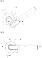
- FIG. 1 shows an actuating element in the form of a door handle 1.
- the door handle has a handle 10 that can be pivoted about an axis of rotation 2, with a door-side first leg 11, the longitudinal axis 2 of which is oriented approximately orthogonally to a door leaf (not shown) in the assembled state and with a angled second leg 16.
- the area where the first and second legs meet at an angle consists of two half-shells 13 which are held together by a nut 15 on the door side and a sleeve 16 on the other side.
- the door handle 1 can have a receptacle for a square shaft 17 in order to couple the door handle to the nut of a box lock in a torque-proof manner.
- a rosette 18 can be provided for fastening and mounting the door handle 1 on a door leaf and can protect the clutch, which is described in more detail below, against manipulation.
- Partially covered by the handle 10 is an output shaft, of which only the square shaft 17 is visible. Rotational movements of the output shaft about the longitudinal axis 2 can be introduced via the square into the nut of a case lock, whereas tilting moments acting orthogonally to the longitudinal axis 2 are preferably at least largely absorbed by the mounting of the handle 10 by the rosette 18 and introduced into the door leaf.
- a shifting clutch in order to connect the handle 10 in a rotationally fixed manner to the output shaft 17 by means of a lock control (shifting clutch closed) or to decouple the two (shifting clutch open).
- the handle 10 is preferably supported on the rosette via a return spring 18, then door handle 1 does not hang down when the clutch is open.
- the rosette 18 in turn can preferably be screwed to the door leaf from the inside of the door or fastened thereto in some other way.
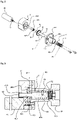
- FIGS 2 and 3 show a linear drive for a coupling element 40.
- the linear drive has a commercially available motor 45 which is attached to a two-part drive carrier 46, which can also be referred to as a gear block.
- the motor 45 drives a gear wheel 44 which is non-rotatably and axially fixed on a clutch shaft 80 (“shaft 80” for short) is seated.
- the shaft 80 is rotatably mounted in the drive carrier and secured against axial displacement.
- a projection 81 designed as a driver 81 which engages between two coils of a coil spring 90 .
- the helical spring 90 is seated coaxially on a journal 82 of the shaft 80 and engages with one of its ends 91 in a slot 463, parallel to the longitudinal axis of the shaft 80, in the drive support 46; at the other end, the coupling element 40 is fastened in a pressure and tensile manner, for example by means of a rivet. Due to the end 91 engaging in the slot 463, the helical spring 90 is seated in the drive carrier 46 in a rotationally fixed but axially displaceable manner. If the shaft 80 is now rotated by means of the motor 45, the projection 81 of the shaft 80 displaces the helical spring 90 in accordance with the direction of rotation of the motor 45 further out of the drive carrier 46 or pulls the coil spring 90 back. The corresponding displacement of the helical spring 90 causes a corresponding displacement of the coupling element 40. If the coupling element 40 should be blocked, it would be biased in the appropriate direction and avoid the bias as soon as the blockage is removed.
- the projection 81 is preferably spaced from the open end of the channel 464 so that the free end of the spring 91 cannot be pushed out of the channel 464 and thus out of the slot 463.
- the distal free end of the shaft 80 also protrudes beyond the pin 81, so that the coil spring 90 even remains on the shaft 80 when the shaft 80 rotates until the projection 81 is unthreaded from the coil spring 90.
- the projection 81 consequently threads itself in again.
- the drive carrier 46 has two parts 461 and 462. On the first part 461 is a mount for the motor 45. In addition, the first part 461 can have a recess in which a bearing bushing 468 with a flange-like widening 467 (“flange 467” for short) or 'edge bead 467') is seated.
- the flange 467 preferably rests on the side facing the projection 81 . Its side facing the projection can then serve as an axial bearing for the shaft 80 .
- the flange 467 supports the gear wheel 44 which is frictionally and/or positively seated on the shaft 80 .
- the side of the flange 467 facing the projection can serve as an axial bearing for the shaft 80, which can be supported on it via the gear wheel 44.
- the second part 462 of the drive carrier preferably has a bearing mount for the shaft 80.
- the bearing mount can, for example, hold a bearing ring 95 which is seated on the shaft 80 and which can also be referred to as a bearing sleeve 95.
- the shaft 80 is expanded in a stepped manner towards the pin 82 .
- the bearing ring rests on the side of the step.
- the bearing ring 95 is axially fixed by the gear wheel 44 fixed to the shaft 80 .
- To assemble the shaft 80 the bearing ring 95 is first pushed onto the shaft 80 from the tapered side of the shaft 80 up to the step.
- the gear wheel 44 is then mounted on the shaft, for example pressed on.
- the bearing pin 83 of the shaft 80 can now be inserted into the bearing bush 468.
- the gear wheel 44 comes into engagement with a complementary drive pinion 451 of the motor 45.
- the motor 45 could also drive a worm which meshes with the gear wheel 44.
- the drive support 56 can now be closed by placing the second part 462 in place be, wherein the gear in a cavity 469, ie a corresponding receptacle 469 of the drive carrier 46 is enclosed.
- the drive carrier 46 has a projection 465 in the form of a slotted sleeve 465, the slot 463 widening on the coupling element side. This facilitates easy threading of a free end 91 of the helical spring 90 .
- the free inner space of the projection 465, i.e. the sleeve, has previously been designated channel 464.
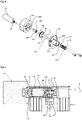
- the embodiment after 4 differs from the embodiment according to Figures 2 and 3 only in that the helical spring 90 is not attached to the coupling element, but only bears against it with the free end.
- the coil spring 90 can therefore only compressive forces on the in 4
- the coupling element 40 is not shown.
- a displacement of the coupling element 40 in the direction of the shaft 80 is effected by a spring element which is arranged on the side of the coupling element 40 facing away from the shaft and which is tensioned when the coupling element is moved into its closed position.
- the widening of the slot 463 on the coupling element side ensures that the free end 91 of the helical spring 90 can always be moved back safely into the sleeve-like projection 465 .
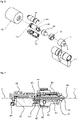
- FIGS. 5 and 6 show a lock cylinder 5 for actuating a box lock.
- the lock cylinder has, as usual, a lock bit ring 17 which is rotatably mounted in the lock cylinder 5.
- a locking cam 9 rotates to actuate a driver for a latch and/or a bolt of a box lock.
- the lock cylinder 5 has a preferably removable knob module as an actuating element 1.
- the knob 10 serves as a handle 10 and is the input shaft of a clutch.
- a two-part drive block 46 is coupled to the handle in a rotationally fixed manner.
- the drive block 46 has a housing of two as a support Half shells 13, 14 and takes on a motor 45 of the clutch.
- the motor 45 is protected by a drilling protection 19, which is also mounted (preferably rotatably) in the drive block (cf. 6 ).
- the motor 45 has a rotor which is connected to a shaft 80 in a rotationally fixed manner.
- On the shaft 80 is a projection 81 designed as a driver 81 which engages between two coils of a coil spring 90 .
- the helical spring 90 is seated coaxially on the shaft 80 and engages with one of its ends 91 in a slot 463, parallel to the longitudinal axis of the shaft 80, in the drive support 46; at the other end is a coupling element 40.
- the coupling element can be fastened to the helical spring in a pressure- and tensile-resistant manner, for example by means of a rivet.
- the coupling element 40 is mounted in a guide 85 so as to be axially displaceable but non-rotatable relative to the drive body 46 . A rotation of the handle 10 about the longitudinal axis is consequently transmitted via the drive carrier 46 to the coupling element 40, ie the coupling element rotates when the handle 10 rotates, ie the guide 85 is non-rotatably connected to the drive carrier.
- the helical spring 90 is seated in the drive carrier 46 in a rotationally fixed but axially displaceable manner through the end engaging in the slot 463. If the shaft 80 is now rotated by means of the motor 45, the projection 81 of the shaft 80 then displaces the helical spring 90 in accordance with the direction of rotation of the motor 45 the drive carrier 46 back or forth. The corresponding displacement of the helical spring 90 causes a corresponding displacement of the coupling element 40 through slots in the guide 85 (cf. 6 ). If the coupling element 40 were to be blocked axially, it would be prestressed in the appropriate direction and avoid the prestressing as soon as the blockage is removed.
- the coupling piece 17 has the function of an output shaft of the clutch.
- the coupling piece 17 has at its Projections or recesses between or into which the coupling element 40 can engage when it is correspondingly displaced by the rotation of the shaft 80.
- the coupling element rotates about the longitudinal axis 2, the lock bit ring 8 is consequently carried along; the clutch is closed.
- the coupling piece 17 and the lock bit ring 8 can also be made in one piece.
- the linear drive shown can be used in a coupling assembly of a shifting clutch for coupling a handle (e.g. a knob) with a lock bit ring of a lock cylinder or for coupling a handle of a door handle with an output shaft, similar to those described above.
- a shifting clutch for coupling a handle (e.g. a knob) with a lock bit ring of a lock cylinder or for coupling a handle of a door handle with an output shaft, similar to those described above.
- the clutch assembly has a drive bracket 46 which supports the motor 45.
- a guide 85 for a coupling element 40 is attached to the drive carrier 46 .
- the drive carrier 45 also supports a circuit board 96 with a circuit, for example for controlling the motor 45, via a circuit carrier 97.
- the motor 45 drives a shaft 80 which is mounted on the drive carrier 46 and the guide 85 and on which a gear wheel 44 is correspondingly seated. which interacts with the drive pinion 46.
- the shaft 80 has a radial projection 81 which engages between two coils of a coil spring 90 as in the other embodiments.
- the coil spring 90 is seated on the shaft 80 in an axially displaceable manner and is fastened to the coupling element 40 .
- the coupling element 40 is mounted in the guide 85 so that it can be displaced axially relative to the shaft 80 (ie, like the helical spring 90, it cannot rotate relative to the guide 85).
- the guide 85 has axially extending radial recesses which serve as guide slots for corresponding projections of the coupling element 40 .
- the helical spring 90 and thus the coupling element 40 are consequently displaced in the guide.
- the coupling element 40 can therefore be displaced axially back and forth on the shaft 80 by a corresponding activation of the motor 45 .
- the coupling element 40 can thus engage with a coupling piece 17 (cf. figure 5 and 6 ) to be brought.
- the shaft 80 is designed as a hollow shaft.
- a conductive pin 86 is arranged in the hollow shaft, the conductive pin 86 being electrically insulated from the drive carrier 46, the hollow shaft 80 and the guide 85 by an air gap and an insulating sleeve 87 on the one hand and an insulating piece 88 on the other.
Landscapes
- Lock And Its Accessories (AREA)
Claims (8)
- Élément d'actionnement (1) d'une serrure à palastre d'une porte, comprenant un arbre de sortie (17) et une clenche (10), qui comportent un axe de rotation commun (2) et qui sont reliés entre eux par un embrayage électromécanique, l'arbre de sortie (17) comportant, au moins du côté dirigé vers la clenche (10), un évidement destiné à un élément d'accouplement (40) apte à coulisser axialement par moteur entre une position ouverte et une position fermée, et la clenche (10) comportant, en face de l'évidement, un logement destiné à l'élément d'accouplement (40), dans lequel- le moteur (45) de l'embrayage électromagnétique entraîne un arbre (80), sur et/ou dans lequel arbre au moins un ressort hélicoïdal (90), solidaire en rotation par rapport aux stator du moteur (45), est disposé coaxialement,- l'arbre (80) comporte au moins une saillie (81) qui s'engage dans un espace ménagé entre deux spires adjacentes du ressort hélicoïdal (90) de sorte qu'une rotation de l'arbre (80) fait coulisser axialement le ressort hélicoïdal (90),- le ressort hélicoïdal (90) s'engage sur l'élément d'accouplement (40) de telle sorte qu'un coulissement axial du ressort hélicoïdal (90) précontraint l'élément d'accouplement (40) au moins dans la direction correspondant au coulissementcaractérisé en ce que
l'élément d'actionnement (1) comporte un support d'entraînement (46) avec un évidement, dans lequel sont logés l'arbre (80) et le ressort hélicoïdal (90), et que le support d'entraînement (46) comporte au moins une fente (463) s'étendant en direction axiale de l'arbre (80), dans laquelle s'engage au moins une extrémité (91) du ressort hélicoïdal (90), de sorte que le ressort hélicoïdal (90) est guidé axialement dans la fente (463). - Élément d'actionnement (1) selon la revendication 1,
caractérisé en ce que
le support d'entraînement (46) comporte un palier lisse pour l'élément d'accouplement (40). - Élément d'actionnement (1) selon la revendication 1 ou 2,
caractérisé en ce que
au moins une roue dentée (44) siège sur l'arbre (80), qui est logée dans un logement du support d'entraînement (46), au moins une partie de la limitation (467) de l'évidement (46) logeant la roue dentée (44) en direction axiale. - Élément d'actionnement (1) selon l'une des revendications 1 à 3,
caractérisé en ce que
le support d'entraînement (46) est réalisé au moins en deux parties, l'arbre (80) étant dégagé en direction axiale lorsque le support d'entraînement est ouvert. - Élément d'actionnement (1) selon l'une des revendications 1 à 4,
caractérisé en ce
qu'au moins un coussinet de palier lisse (469) siège dans le support d'entraînement (46), qui loge l'arbre (80) radialement. - Élément d'actionnement (1) selon l'une des revendications 1 à 5,
caractérisé en ce que
au moins un manchon de palier lisse (95) siège sur l'arbre (80), qui forme un palier lisse avec le support d'entraînement (46). - Élément d'actionnement (1) selon la revendication 5 ou 6,
caractérisé en ce que
l'arbre (80) est rétréci en gradins et est posé avec le gradin sur une face frontale du coussinet de palier lisse (468) ou du manchon de palier lisse (95), de sorte que l'arbre (80) est logé axialement dans cette direction. - Élément d'actionnement (1) selon l'une des revendications précédentes, caractérisé en ce que
le ressort hélicoïdal (90) est fixé à l'élément d'accouplement (40) par traction et par pression.
Applications Claiming Priority (2)
| Application Number | Priority Date | Filing Date | Title |
|---|---|---|---|
| DE102015112859.4A DE102015112859B3 (de) | 2015-08-05 | 2015-08-05 | Türdrücker und Antriebsträger |
| PCT/EP2016/068435 WO2017021410A1 (fr) | 2015-08-05 | 2016-08-02 | Élément d'actionnement pour une serrure à palastre |
Publications (2)
| Publication Number | Publication Date |
|---|---|
| EP3207197A1 EP3207197A1 (fr) | 2017-08-23 |
| EP3207197B1 true EP3207197B1 (fr) | 2022-06-15 |
Family
ID=56557709
Family Applications (1)
| Application Number | Title | Priority Date | Filing Date |
|---|---|---|---|
| EP16745485.9A Active EP3207197B1 (fr) | 2015-08-05 | 2016-08-02 | Élément d'actionnement pour une serrure à palastre |
Country Status (5)
| Country | Link |
|---|---|
| US (1) | US10927569B2 (fr) |
| EP (1) | EP3207197B1 (fr) |
| DE (1) | DE102015112859B3 (fr) |
| ES (1) | ES2926957T3 (fr) |
| WO (1) | WO2017021410A1 (fr) |
Families Citing this family (11)
| Publication number | Priority date | Publication date | Assignee | Title |
|---|---|---|---|---|
| CN106246003B (zh) * | 2016-09-20 | 2018-11-27 | 东莞市锁之道科技有限公司 | 一种用于锁定装置的电动机构 |
| DK3460149T3 (da) | 2017-09-22 | 2020-02-24 | C Ed Schulte Ges Mit Beschraenkter Haftung Zylinderschlossfabrik | Aktuator, lukkemekanisme, elektromekanisk dørlås og brug af og fremgangsmåde til samme |
| EP3636861B1 (fr) * | 2018-10-12 | 2021-08-04 | SimonsVoss Technologies GmbH | Actionneur destiné à une serrure électrique et procédé d'actionnement d'une serrure électrique |
| GB2586018A (en) * | 2019-07-29 | 2021-02-03 | Colin Powell Simon | Electrically-Operated Lock |
| CN110541617A (zh) * | 2019-09-16 | 2019-12-06 | 深圳市帝磁物联网科技有限公司 | 一种新型电插锁结构 |
| CN111140106B (zh) * | 2020-02-27 | 2022-03-29 | 珠海优特物联科技有限公司 | 一种锁定机构、锁芯及锁具 |
| CN111335743A (zh) * | 2020-04-13 | 2020-06-26 | 宁波大榭开发区佳洁锌铸件有限公司 | 一种指纹锁的离合装置 |
| CN113188739B (zh) * | 2021-04-22 | 2022-08-26 | 内蒙古工业大学 | 一种用于机电设备生产的振动检验装置 |
| KR102581603B1 (ko) | 2021-11-10 | 2023-09-22 | 중앙대학교 산학협력단 | 발목 관절 가변 압박 신발 및 압박력 제어방법 |
| ES3032209T3 (en) | 2022-05-03 | 2025-07-16 | Uhlmann & Zacher Gmbh | Clutch actuator for a door lock |
| EP4491836B1 (fr) | 2023-07-11 | 2025-10-15 | Uhlmann & Zacher GmbH | Ensemble de rappel de poignée et poignée pour une porte ou une fenêtre |
Citations (1)
| Publication number | Priority date | Publication date | Assignee | Title |
|---|---|---|---|---|
| WO1998015703A1 (fr) * | 1996-10-08 | 1998-04-16 | Lucky Lock Ltd. | Serrure electromecanique |
Family Cites Families (23)
| Publication number | Priority date | Publication date | Assignee | Title |
|---|---|---|---|---|
| US5083122A (en) * | 1989-02-21 | 1992-01-21 | Osi Security Devices | Programmable individualized security system for door locks |
| US5018375A (en) * | 1990-09-18 | 1991-05-28 | Yale Security Inc. | Lockset having electric means for disabling and enabling the outer handle |
| US5628216A (en) * | 1995-01-13 | 1997-05-13 | Schlage Lock Company | Locking device |
| DE19854454C2 (de) | 1998-11-13 | 2000-09-07 | Ulf Klenk | Schließzylinder |
| US6041630A (en) * | 1999-03-12 | 2000-03-28 | Shen; Mu-Lin | Clutch mechanism for a lock |
| US6460903B1 (en) * | 2000-10-31 | 2002-10-08 | Summit Automation Co., Ltd | Locking mechanism of electronic lock |
| GB2390394B (en) * | 2002-07-03 | 2004-05-26 | Shyang Feng Electric & Machine | Improved electronic lock |
| ITBO20030582A1 (it) * | 2003-10-10 | 2005-04-11 | Cisa Spa | Serratura elettrica provvista di molla multifunzione |
| DE102004057747A1 (de) * | 2004-11-30 | 2006-06-01 | Normbau Beschläge und Ausstattungs GmbH | Kupplungsvorrichtung für eine Verriegelungstechnik |
| US7918114B2 (en) * | 2005-07-07 | 2011-04-05 | Harrow Products Llc | Electronic lock actuator with helical drive member |
| ES2323201B1 (es) * | 2006-06-26 | 2010-04-20 | Salto Systems S.L. | Mecanismo de embrague acoplable a cerraduras de puertas con pestillo de cierre accionado por manillas o pomos. |
| TWM365969U (en) * | 2008-11-14 | 2009-10-01 | bang-zheng Liu | Electric lock-latch driver |
| DE102009018471B4 (de) * | 2009-04-22 | 2021-02-04 | SÜD-Metall Schließsysteme Leipzig GmbH | Lock-Box mit Piezomotor |
| DE202009011110U1 (de) * | 2009-08-14 | 2009-12-03 | Wfe Technology Corp. | Hin- und hergehende Vorrichtung mit einem Blockierverhinderungs-Mechanismus |
| SE534640C2 (sv) * | 2010-03-23 | 2011-11-01 | Assa Oem Ab | Handtagsanordning med aktiveringsorgan, ingreppsorgan och elektrisk drivanordning |
| US8356499B2 (en) * | 2010-07-08 | 2013-01-22 | Fu Chang Locks Mfg Corp. | Electric lock |
| CN102953598B (zh) * | 2011-08-17 | 2015-08-19 | 东莞市锁之道科技有限公司 | 锁的电动机构 |
| TWI458882B (zh) * | 2012-05-15 | 2014-11-01 | Wfe Technology Corp | 電子鎖之作動馬達組 |
| TWM451410U (zh) * | 2012-09-21 | 2013-04-21 | Tong Lung Metal Ind Co Ltd | 電子鎖的傳動機構 |
| DE102014103666C9 (de) * | 2014-03-18 | 2019-06-06 | Günter Uhlmann | Türdrücker |
| US10047544B2 (en) * | 2014-04-17 | 2018-08-14 | Tlhm Co., Ltd. | Transmission device of electronic lock |
| US9181730B1 (en) * | 2014-12-18 | 2015-11-10 | Fu-Chang Peng | Driving structure of electronic lock |
| US10465423B2 (en) * | 2017-03-08 | 2019-11-05 | Sargent Manufacturing Company | Locking mechanism for bored lock |
-
2015
- 2015-08-05 DE DE102015112859.4A patent/DE102015112859B3/de active Active
-
2016
- 2016-08-02 WO PCT/EP2016/068435 patent/WO2017021410A1/fr not_active Ceased
- 2016-08-02 ES ES16745485T patent/ES2926957T3/es active Active
- 2016-08-02 EP EP16745485.9A patent/EP3207197B1/fr active Active
-
2018
- 2018-02-05 US US15/888,742 patent/US10927569B2/en active Active
Patent Citations (1)
| Publication number | Priority date | Publication date | Assignee | Title |
|---|---|---|---|---|
| WO1998015703A1 (fr) * | 1996-10-08 | 1998-04-16 | Lucky Lock Ltd. | Serrure electromecanique |
Also Published As
| Publication number | Publication date |
|---|---|
| ES2926957T3 (es) | 2022-10-31 |
| US20180155961A1 (en) | 2018-06-07 |
| US10927569B2 (en) | 2021-02-23 |
| DE102015112859B3 (de) | 2016-11-03 |
| WO2017021410A1 (fr) | 2017-02-09 |
| EP3207197A1 (fr) | 2017-08-23 |
Similar Documents
| Publication | Publication Date | Title |
|---|---|---|
| EP3058154B2 (fr) | Poignée de porte | |
| DE102015112859B3 (de) | Türdrücker und Antriebsträger | |
| EP1636454B1 (fr) | Barillet electromagnetique | |
| DE102007044088A1 (de) | Binär codierter Schlüssel und manipulationssicheres Schloss | |
| EP3372760B1 (fr) | Unité électronique pour un dispositif de verrouillage et système de fermeture | |
| EP0819810B1 (fr) | Ferrure pour une serrure | |
| DE102008063061A1 (de) | Betätigungsvorrichtung für ein elektronisches Türschloß | |
| WO2003078766A1 (fr) | Serrure | |
| DE102008056627C5 (de) | Profilzylinderschloss mit einstückigem radialem Gehäuseansatz und mit automatischer Rückstellvorrichtung für einen Schließbart oder Mitnehmerkörper | |
| EP2561164B1 (fr) | Agencement de cylindre de fermeture | |
| EP4386158B1 (fr) | Ouvre-porte | |
| EP3460149A1 (fr) | Actionneur, mécanisme de verrouillage, verrou électromécanique ainsi que leur utilisation et procédé correspondant | |
| EP3034719B1 (fr) | Dispositif d'actionnement d'un mecanisme de verrouillage d'une porte ou d'une fenetre | |
| DE102004046778A1 (de) | Schließzylinder mit erhöhter Eingriffssicherheit | |
| DE102007011554B4 (de) | Koppeleinheit für elektronische Schließ-Systeme | |
| DE102004009992A1 (de) | Handhabe für ein Türschloss und Schloss mit derartiger Handhabe | |
| DE102004056989B4 (de) | Schließvorrichtung | |
| DE102006020614B4 (de) | Schloss mit automatischer Rückstellung des Schließbarts | |
| DE102012110484A1 (de) | Elektromechanische Kupplung für ein Panikschloss | |
| DE102019113666A1 (de) | Schließzylinder | |
| DE202005020043U1 (de) | Verriegelungsvorrichtung | |
| WO2023011874A1 (fr) | Poignée de porte | |
| EP4112856B1 (fr) | Serrure dotée d'un verrou pouvant tourner à l'aide d'un élément d'actionnement | |
| EP3203001A1 (fr) | Dispositif de butée pour un ouvre-porte | |
| EP3892802B1 (fr) | Agencement de poignée de porte |
Legal Events
| Date | Code | Title | Description |
|---|---|---|---|
| STAA | Information on the status of an ep patent application or granted ep patent |
Free format text: STATUS: THE INTERNATIONAL PUBLICATION HAS BEEN MADE |
|
| PUAI | Public reference made under article 153(3) epc to a published international application that has entered the european phase |
Free format text: ORIGINAL CODE: 0009012 |
|
| STAA | Information on the status of an ep patent application or granted ep patent |
Free format text: STATUS: REQUEST FOR EXAMINATION WAS MADE |
|
| 17P | Request for examination filed |
Effective date: 20170515 |
|
| AK | Designated contracting states |
Kind code of ref document: A1 Designated state(s): AL AT BE BG CH CY CZ DE DK EE ES FI FR GB GR HR HU IE IS IT LI LT LU LV MC MK MT NL NO PL PT RO RS SE SI SK SM TR |
|
| AX | Request for extension of the european patent |
Extension state: BA ME |
|
| STAA | Information on the status of an ep patent application or granted ep patent |
Free format text: STATUS: EXAMINATION IS IN PROGRESS |
|
| 17Q | First examination report despatched |
Effective date: 20180314 |
|
| DAV | Request for validation of the european patent (deleted) | ||
| DAX | Request for extension of the european patent (deleted) | ||
| GRAP | Despatch of communication of intention to grant a patent |
Free format text: ORIGINAL CODE: EPIDOSNIGR1 |
|
| STAA | Information on the status of an ep patent application or granted ep patent |
Free format text: STATUS: GRANT OF PATENT IS INTENDED |
|
| INTG | Intention to grant announced |
Effective date: 20210714 |
|
| GRAS | Grant fee paid |
Free format text: ORIGINAL CODE: EPIDOSNIGR3 |
|
| GRAJ | Information related to disapproval of communication of intention to grant by the applicant or resumption of examination proceedings by the epo deleted |
Free format text: ORIGINAL CODE: EPIDOSDIGR1 |
|
| GRAL | Information related to payment of fee for publishing/printing deleted |
Free format text: ORIGINAL CODE: EPIDOSDIGR3 |
|
| STAA | Information on the status of an ep patent application or granted ep patent |
Free format text: STATUS: EXAMINATION IS IN PROGRESS |
|
| INTC | Intention to grant announced (deleted) | ||
| GRAP | Despatch of communication of intention to grant a patent |
Free format text: ORIGINAL CODE: EPIDOSNIGR1 |
|
| STAA | Information on the status of an ep patent application or granted ep patent |
Free format text: STATUS: GRANT OF PATENT IS INTENDED |
|
| INTG | Intention to grant announced |
Effective date: 20220223 |
|
| GRAA | (expected) grant |
Free format text: ORIGINAL CODE: 0009210 |
|
| STAA | Information on the status of an ep patent application or granted ep patent |
Free format text: STATUS: THE PATENT HAS BEEN GRANTED |
|
| AK | Designated contracting states |
Kind code of ref document: B1 Designated state(s): AL AT BE BG CH CY CZ DE DK EE ES FI FR GB GR HR HU IE IS IT LI LT LU LV MC MK MT NL NO PL PT RO RS SE SI SK SM TR |
|
| REG | Reference to a national code |
Ref country code: CH Ref legal event code: EP Ref country code: GB Ref legal event code: FG4D Free format text: NOT ENGLISH |
|
| REG | Reference to a national code |
Ref country code: IE Ref legal event code: FG4D Free format text: LANGUAGE OF EP DOCUMENT: GERMAN |
|
| REG | Reference to a national code |
Ref country code: DE Ref legal event code: R096 Ref document number: 502016014969 Country of ref document: DE |
|
| REG | Reference to a national code |
Ref country code: AT Ref legal event code: REF Ref document number: 1498502 Country of ref document: AT Kind code of ref document: T Effective date: 20220715 |
|
| REG | Reference to a national code |
Ref country code: SE Ref legal event code: TRGR |
|
| REG | Reference to a national code |
Ref country code: LT Ref legal event code: MG9D |
|
| REG | Reference to a national code |
Ref country code: NL Ref legal event code: MP Effective date: 20220615 |
|
| PG25 | Lapsed in a contracting state [announced via postgrant information from national office to epo] |
Ref country code: NO Free format text: LAPSE BECAUSE OF FAILURE TO SUBMIT A TRANSLATION OF THE DESCRIPTION OR TO PAY THE FEE WITHIN THE PRESCRIBED TIME-LIMIT Effective date: 20220915 Ref country code: LT Free format text: LAPSE BECAUSE OF FAILURE TO SUBMIT A TRANSLATION OF THE DESCRIPTION OR TO PAY THE FEE WITHIN THE PRESCRIBED TIME-LIMIT Effective date: 20220615 Ref country code: HR Free format text: LAPSE BECAUSE OF FAILURE TO SUBMIT A TRANSLATION OF THE DESCRIPTION OR TO PAY THE FEE WITHIN THE PRESCRIBED TIME-LIMIT Effective date: 20220615 Ref country code: GR Free format text: LAPSE BECAUSE OF FAILURE TO SUBMIT A TRANSLATION OF THE DESCRIPTION OR TO PAY THE FEE WITHIN THE PRESCRIBED TIME-LIMIT Effective date: 20220916 Ref country code: FI Free format text: LAPSE BECAUSE OF FAILURE TO SUBMIT A TRANSLATION OF THE DESCRIPTION OR TO PAY THE FEE WITHIN THE PRESCRIBED TIME-LIMIT Effective date: 20220615 Ref country code: BG Free format text: LAPSE BECAUSE OF FAILURE TO SUBMIT A TRANSLATION OF THE DESCRIPTION OR TO PAY THE FEE WITHIN THE PRESCRIBED TIME-LIMIT Effective date: 20220915 |
|
| REG | Reference to a national code |
Ref country code: ES Ref legal event code: FG2A Ref document number: 2926957 Country of ref document: ES Kind code of ref document: T3 Effective date: 20221031 |
|
| PG25 | Lapsed in a contracting state [announced via postgrant information from national office to epo] |
Ref country code: RS Free format text: LAPSE BECAUSE OF FAILURE TO SUBMIT A TRANSLATION OF THE DESCRIPTION OR TO PAY THE FEE WITHIN THE PRESCRIBED TIME-LIMIT Effective date: 20220615 Ref country code: LV Free format text: LAPSE BECAUSE OF FAILURE TO SUBMIT A TRANSLATION OF THE DESCRIPTION OR TO PAY THE FEE WITHIN THE PRESCRIBED TIME-LIMIT Effective date: 20220615 |
|
| PG25 | Lapsed in a contracting state [announced via postgrant information from national office to epo] |
Ref country code: NL Free format text: LAPSE BECAUSE OF FAILURE TO SUBMIT A TRANSLATION OF THE DESCRIPTION OR TO PAY THE FEE WITHIN THE PRESCRIBED TIME-LIMIT Effective date: 20220615 |
|
| PG25 | Lapsed in a contracting state [announced via postgrant information from national office to epo] |
Ref country code: SM Free format text: LAPSE BECAUSE OF FAILURE TO SUBMIT A TRANSLATION OF THE DESCRIPTION OR TO PAY THE FEE WITHIN THE PRESCRIBED TIME-LIMIT Effective date: 20220615 Ref country code: SK Free format text: LAPSE BECAUSE OF FAILURE TO SUBMIT A TRANSLATION OF THE DESCRIPTION OR TO PAY THE FEE WITHIN THE PRESCRIBED TIME-LIMIT Effective date: 20220615 Ref country code: RO Free format text: LAPSE BECAUSE OF FAILURE TO SUBMIT A TRANSLATION OF THE DESCRIPTION OR TO PAY THE FEE WITHIN THE PRESCRIBED TIME-LIMIT Effective date: 20220615 Ref country code: PT Free format text: LAPSE BECAUSE OF FAILURE TO SUBMIT A TRANSLATION OF THE DESCRIPTION OR TO PAY THE FEE WITHIN THE PRESCRIBED TIME-LIMIT Effective date: 20221017 Ref country code: EE Free format text: LAPSE BECAUSE OF FAILURE TO SUBMIT A TRANSLATION OF THE DESCRIPTION OR TO PAY THE FEE WITHIN THE PRESCRIBED TIME-LIMIT Effective date: 20220615 Ref country code: CZ Free format text: LAPSE BECAUSE OF FAILURE TO SUBMIT A TRANSLATION OF THE DESCRIPTION OR TO PAY THE FEE WITHIN THE PRESCRIBED TIME-LIMIT Effective date: 20220615 |
|
| PG25 | Lapsed in a contracting state [announced via postgrant information from national office to epo] |
Ref country code: PL Free format text: LAPSE BECAUSE OF FAILURE TO SUBMIT A TRANSLATION OF THE DESCRIPTION OR TO PAY THE FEE WITHIN THE PRESCRIBED TIME-LIMIT Effective date: 20220615 Ref country code: IS Free format text: LAPSE BECAUSE OF FAILURE TO SUBMIT A TRANSLATION OF THE DESCRIPTION OR TO PAY THE FEE WITHIN THE PRESCRIBED TIME-LIMIT Effective date: 20221015 |
|
| REG | Reference to a national code |
Ref country code: DE Ref legal event code: R097 Ref document number: 502016014969 Country of ref document: DE |
|
| PG25 | Lapsed in a contracting state [announced via postgrant information from national office to epo] |
Ref country code: MC Free format text: LAPSE BECAUSE OF FAILURE TO SUBMIT A TRANSLATION OF THE DESCRIPTION OR TO PAY THE FEE WITHIN THE PRESCRIBED TIME-LIMIT Effective date: 20220615 Ref country code: AL Free format text: LAPSE BECAUSE OF FAILURE TO SUBMIT A TRANSLATION OF THE DESCRIPTION OR TO PAY THE FEE WITHIN THE PRESCRIBED TIME-LIMIT Effective date: 20220615 |
|
| PLBE | No opposition filed within time limit |
Free format text: ORIGINAL CODE: 0009261 |
|
| STAA | Information on the status of an ep patent application or granted ep patent |
Free format text: STATUS: NO OPPOSITION FILED WITHIN TIME LIMIT |
|
| PG25 | Lapsed in a contracting state [announced via postgrant information from national office to epo] |
Ref country code: LU Free format text: LAPSE BECAUSE OF NON-PAYMENT OF DUE FEES Effective date: 20220802 Ref country code: DK Free format text: LAPSE BECAUSE OF FAILURE TO SUBMIT A TRANSLATION OF THE DESCRIPTION OR TO PAY THE FEE WITHIN THE PRESCRIBED TIME-LIMIT Effective date: 20220615 |
|
| REG | Reference to a national code |
Ref country code: BE Ref legal event code: MM Effective date: 20220831 |
|
| 26N | No opposition filed |
Effective date: 20230316 |
|
| GBPC | Gb: european patent ceased through non-payment of renewal fee |
Effective date: 20220915 |
|
| PG25 | Lapsed in a contracting state [announced via postgrant information from national office to epo] |
Ref country code: SI Free format text: LAPSE BECAUSE OF FAILURE TO SUBMIT A TRANSLATION OF THE DESCRIPTION OR TO PAY THE FEE WITHIN THE PRESCRIBED TIME-LIMIT Effective date: 20220615 |
|
| PG25 | Lapsed in a contracting state [announced via postgrant information from national office to epo] |
Ref country code: IE Free format text: LAPSE BECAUSE OF NON-PAYMENT OF DUE FEES Effective date: 20220802 |
|
| PG25 | Lapsed in a contracting state [announced via postgrant information from national office to epo] |
Ref country code: BE Free format text: LAPSE BECAUSE OF NON-PAYMENT OF DUE FEES Effective date: 20220831 |
|
| PG25 | Lapsed in a contracting state [announced via postgrant information from national office to epo] |
Ref country code: GB Free format text: LAPSE BECAUSE OF NON-PAYMENT OF DUE FEES Effective date: 20220915 |
|
| PG25 | Lapsed in a contracting state [announced via postgrant information from national office to epo] |
Ref country code: IT Free format text: LAPSE BECAUSE OF FAILURE TO SUBMIT A TRANSLATION OF THE DESCRIPTION OR TO PAY THE FEE WITHIN THE PRESCRIBED TIME-LIMIT Effective date: 20220615 |
|
| PG25 | Lapsed in a contracting state [announced via postgrant information from national office to epo] |
Ref country code: HU Free format text: LAPSE BECAUSE OF FAILURE TO SUBMIT A TRANSLATION OF THE DESCRIPTION OR TO PAY THE FEE WITHIN THE PRESCRIBED TIME-LIMIT; INVALID AB INITIO Effective date: 20160802 |
|
| PG25 | Lapsed in a contracting state [announced via postgrant information from national office to epo] |
Ref country code: MK Free format text: LAPSE BECAUSE OF FAILURE TO SUBMIT A TRANSLATION OF THE DESCRIPTION OR TO PAY THE FEE WITHIN THE PRESCRIBED TIME-LIMIT Effective date: 20220615 Ref country code: CY Free format text: LAPSE BECAUSE OF FAILURE TO SUBMIT A TRANSLATION OF THE DESCRIPTION OR TO PAY THE FEE WITHIN THE PRESCRIBED TIME-LIMIT Effective date: 20220615 |
|
| PG25 | Lapsed in a contracting state [announced via postgrant information from national office to epo] |
Ref country code: TR Free format text: LAPSE BECAUSE OF FAILURE TO SUBMIT A TRANSLATION OF THE DESCRIPTION OR TO PAY THE FEE WITHIN THE PRESCRIBED TIME-LIMIT Effective date: 20220615 |
|
| PG25 | Lapsed in a contracting state [announced via postgrant information from national office to epo] |
Ref country code: MT Free format text: LAPSE BECAUSE OF FAILURE TO SUBMIT A TRANSLATION OF THE DESCRIPTION OR TO PAY THE FEE WITHIN THE PRESCRIBED TIME-LIMIT Effective date: 20220615 |
|
| PG25 | Lapsed in a contracting state [announced via postgrant information from national office to epo] |
Ref country code: BG Free format text: LAPSE BECAUSE OF FAILURE TO SUBMIT A TRANSLATION OF THE DESCRIPTION OR TO PAY THE FEE WITHIN THE PRESCRIBED TIME-LIMIT Effective date: 20220615 |
|
| PG25 | Lapsed in a contracting state [announced via postgrant information from national office to epo] |
Ref country code: BG Free format text: LAPSE BECAUSE OF FAILURE TO SUBMIT A TRANSLATION OF THE DESCRIPTION OR TO PAY THE FEE WITHIN THE PRESCRIBED TIME-LIMIT Effective date: 20220615 |
|
| PGFP | Annual fee paid to national office [announced via postgrant information from national office to epo] |
Ref country code: ES Payment date: 20250917 Year of fee payment: 10 |
|
| PGFP | Annual fee paid to national office [announced via postgrant information from national office to epo] |
Ref country code: DE Payment date: 20250821 Year of fee payment: 10 |
|
| PGFP | Annual fee paid to national office [announced via postgrant information from national office to epo] |
Ref country code: FR Payment date: 20250821 Year of fee payment: 10 Ref country code: AT Payment date: 20250819 Year of fee payment: 10 |
|
| PGFP | Annual fee paid to national office [announced via postgrant information from national office to epo] |
Ref country code: CH Payment date: 20250901 Year of fee payment: 10 Ref country code: SE Payment date: 20250821 Year of fee payment: 10 |