EP3207267B1 - Lageranordnung für eine tiefbohreinrichtung - Google Patents
Lageranordnung für eine tiefbohreinrichtung Download PDFInfo
- Publication number
- EP3207267B1 EP3207267B1 EP15790447.5A EP15790447A EP3207267B1 EP 3207267 B1 EP3207267 B1 EP 3207267B1 EP 15790447 A EP15790447 A EP 15790447A EP 3207267 B1 EP3207267 B1 EP 3207267B1
- Authority
- EP
- European Patent Office
- Prior art keywords
- bearing
- rings
- bearing rings
- arrangement according
- shoulder surfaces
- Prior art date
- Legal status (The legal status is an assumption and is not a legal conclusion. Google has not performed a legal analysis and makes no representation as to the accuracy of the status listed.)
- Active
Links
Images

Classifications
-
- F—MECHANICAL ENGINEERING; LIGHTING; HEATING; WEAPONS; BLASTING
- F16—ENGINEERING ELEMENTS AND UNITS; GENERAL MEASURES FOR PRODUCING AND MAINTAINING EFFECTIVE FUNCTIONING OF MACHINES OR INSTALLATIONS; THERMAL INSULATION IN GENERAL
- F16C—SHAFTS; FLEXIBLE SHAFTS; ELEMENTS OR CRANKSHAFT MECHANISMS; ROTARY BODIES OTHER THAN GEARING ELEMENTS; BEARINGS
- F16C33/00—Parts of bearings; Special methods for making bearings or parts thereof
- F16C33/30—Parts of ball or roller bearings
- F16C33/66—Special parts or details in view of lubrication
- F16C33/6637—Special parts or details in view of lubrication with liquid lubricant
- F16C33/6681—Details of distribution or circulation inside the bearing, e.g. grooves on the cage or passages in the rolling elements
-
- F—MECHANICAL ENGINEERING; LIGHTING; HEATING; WEAPONS; BLASTING
- F16—ENGINEERING ELEMENTS AND UNITS; GENERAL MEASURES FOR PRODUCING AND MAINTAINING EFFECTIVE FUNCTIONING OF MACHINES OR INSTALLATIONS; THERMAL INSULATION IN GENERAL
- F16C—SHAFTS; FLEXIBLE SHAFTS; ELEMENTS OR CRANKSHAFT MECHANISMS; ROTARY BODIES OTHER THAN GEARING ELEMENTS; BEARINGS
- F16C17/00—Sliding-contact bearings for exclusively rotary movement
- F16C17/02—Sliding-contact bearings for exclusively rotary movement for radial load only
-
- F—MECHANICAL ENGINEERING; LIGHTING; HEATING; WEAPONS; BLASTING
- F16—ENGINEERING ELEMENTS AND UNITS; GENERAL MEASURES FOR PRODUCING AND MAINTAINING EFFECTIVE FUNCTIONING OF MACHINES OR INSTALLATIONS; THERMAL INSULATION IN GENERAL
- F16C—SHAFTS; FLEXIBLE SHAFTS; ELEMENTS OR CRANKSHAFT MECHANISMS; ROTARY BODIES OTHER THAN GEARING ELEMENTS; BEARINGS
- F16C19/00—Bearings with rolling contact, for exclusively rotary movement
- F16C19/02—Bearings with rolling contact, for exclusively rotary movement with bearing balls essentially of the same size in one or more circular rows
- F16C19/04—Bearings with rolling contact, for exclusively rotary movement with bearing balls essentially of the same size in one or more circular rows for radial load mainly
- F16C19/08—Bearings with rolling contact, for exclusively rotary movement with bearing balls essentially of the same size in one or more circular rows for radial load mainly with two or more rows of balls
-
- F—MECHANICAL ENGINEERING; LIGHTING; HEATING; WEAPONS; BLASTING
- F16—ENGINEERING ELEMENTS AND UNITS; GENERAL MEASURES FOR PRODUCING AND MAINTAINING EFFECTIVE FUNCTIONING OF MACHINES OR INSTALLATIONS; THERMAL INSULATION IN GENERAL
- F16C—SHAFTS; FLEXIBLE SHAFTS; ELEMENTS OR CRANKSHAFT MECHANISMS; ROTARY BODIES OTHER THAN GEARING ELEMENTS; BEARINGS
- F16C19/00—Bearings with rolling contact, for exclusively rotary movement
- F16C19/02—Bearings with rolling contact, for exclusively rotary movement with bearing balls essentially of the same size in one or more circular rows
- F16C19/14—Bearings with rolling contact, for exclusively rotary movement with bearing balls essentially of the same size in one or more circular rows for both radial and axial load
- F16C19/18—Bearings with rolling contact, for exclusively rotary movement with bearing balls essentially of the same size in one or more circular rows for both radial and axial load with two or more rows of balls
- F16C19/181—Bearings with rolling contact, for exclusively rotary movement with bearing balls essentially of the same size in one or more circular rows for both radial and axial load with two or more rows of balls with angular contact
-
- F—MECHANICAL ENGINEERING; LIGHTING; HEATING; WEAPONS; BLASTING
- F16—ENGINEERING ELEMENTS AND UNITS; GENERAL MEASURES FOR PRODUCING AND MAINTAINING EFFECTIVE FUNCTIONING OF MACHINES OR INSTALLATIONS; THERMAL INSULATION IN GENERAL
- F16C—SHAFTS; FLEXIBLE SHAFTS; ELEMENTS OR CRANKSHAFT MECHANISMS; ROTARY BODIES OTHER THAN GEARING ELEMENTS; BEARINGS
- F16C19/00—Bearings with rolling contact, for exclusively rotary movement
- F16C19/52—Bearings with rolling contact, for exclusively rotary movement with devices affected by abnormal or undesired conditions
- F16C19/522—Bearings with rolling contact, for exclusively rotary movement with devices affected by abnormal or undesired conditions related to load on the bearing, e.g. bearings with load sensors or means to protect the bearing against overload
-
- F—MECHANICAL ENGINEERING; LIGHTING; HEATING; WEAPONS; BLASTING
- F16—ENGINEERING ELEMENTS AND UNITS; GENERAL MEASURES FOR PRODUCING AND MAINTAINING EFFECTIVE FUNCTIONING OF MACHINES OR INSTALLATIONS; THERMAL INSULATION IN GENERAL
- F16C—SHAFTS; FLEXIBLE SHAFTS; ELEMENTS OR CRANKSHAFT MECHANISMS; ROTARY BODIES OTHER THAN GEARING ELEMENTS; BEARINGS
- F16C21/00—Combinations of sliding-contact bearings with ball or roller bearings, for exclusively rotary movement
-
- F—MECHANICAL ENGINEERING; LIGHTING; HEATING; WEAPONS; BLASTING
- F16—ENGINEERING ELEMENTS AND UNITS; GENERAL MEASURES FOR PRODUCING AND MAINTAINING EFFECTIVE FUNCTIONING OF MACHINES OR INSTALLATIONS; THERMAL INSULATION IN GENERAL
- F16C—SHAFTS; FLEXIBLE SHAFTS; ELEMENTS OR CRANKSHAFT MECHANISMS; ROTARY BODIES OTHER THAN GEARING ELEMENTS; BEARINGS
- F16C33/00—Parts of bearings; Special methods for making bearings or parts thereof
- F16C33/30—Parts of ball or roller bearings
- F16C33/37—Loose spacing bodies
- F16C33/3713—Loose spacing bodies with other rolling elements serving as spacing bodies, e.g. the spacing bodies are in rolling contact with the load carrying rolling elements
-
- F—MECHANICAL ENGINEERING; LIGHTING; HEATING; WEAPONS; BLASTING
- F16—ENGINEERING ELEMENTS AND UNITS; GENERAL MEASURES FOR PRODUCING AND MAINTAINING EFFECTIVE FUNCTIONING OF MACHINES OR INSTALLATIONS; THERMAL INSULATION IN GENERAL
- F16C—SHAFTS; FLEXIBLE SHAFTS; ELEMENTS OR CRANKSHAFT MECHANISMS; ROTARY BODIES OTHER THAN GEARING ELEMENTS; BEARINGS
- F16C33/00—Parts of bearings; Special methods for making bearings or parts thereof
- F16C33/30—Parts of ball or roller bearings
- F16C33/58—Raceways; Race rings
- F16C33/60—Raceways; Race rings divided or split, e.g. comprising two juxtaposed rings
-
- F—MECHANICAL ENGINEERING; LIGHTING; HEATING; WEAPONS; BLASTING
- F16—ENGINEERING ELEMENTS AND UNITS; GENERAL MEASURES FOR PRODUCING AND MAINTAINING EFFECTIVE FUNCTIONING OF MACHINES OR INSTALLATIONS; THERMAL INSULATION IN GENERAL
- F16C—SHAFTS; FLEXIBLE SHAFTS; ELEMENTS OR CRANKSHAFT MECHANISMS; ROTARY BODIES OTHER THAN GEARING ELEMENTS; BEARINGS
- F16C39/00—Relieving load on bearings
- F16C39/02—Relieving load on bearings using mechanical means
-
- F—MECHANICAL ENGINEERING; LIGHTING; HEATING; WEAPONS; BLASTING
- F16—ENGINEERING ELEMENTS AND UNITS; GENERAL MEASURES FOR PRODUCING AND MAINTAINING EFFECTIVE FUNCTIONING OF MACHINES OR INSTALLATIONS; THERMAL INSULATION IN GENERAL
- F16C—SHAFTS; FLEXIBLE SHAFTS; ELEMENTS OR CRANKSHAFT MECHANISMS; ROTARY BODIES OTHER THAN GEARING ELEMENTS; BEARINGS
- F16C2240/00—Specified values or numerical ranges of parameters; Relations between them
- F16C2240/40—Linear dimensions, e.g. length, radius, thickness, gap
- F16C2240/46—Gap sizes or clearances
-
- F—MECHANICAL ENGINEERING; LIGHTING; HEATING; WEAPONS; BLASTING
- F16—ENGINEERING ELEMENTS AND UNITS; GENERAL MEASURES FOR PRODUCING AND MAINTAINING EFFECTIVE FUNCTIONING OF MACHINES OR INSTALLATIONS; THERMAL INSULATION IN GENERAL
- F16C—SHAFTS; FLEXIBLE SHAFTS; ELEMENTS OR CRANKSHAFT MECHANISMS; ROTARY BODIES OTHER THAN GEARING ELEMENTS; BEARINGS
- F16C2240/00—Specified values or numerical ranges of parameters; Relations between them
- F16C2240/40—Linear dimensions, e.g. length, radius, thickness, gap
- F16C2240/70—Diameters; Radii
-
- F—MECHANICAL ENGINEERING; LIGHTING; HEATING; WEAPONS; BLASTING
- F16—ENGINEERING ELEMENTS AND UNITS; GENERAL MEASURES FOR PRODUCING AND MAINTAINING EFFECTIVE FUNCTIONING OF MACHINES OR INSTALLATIONS; THERMAL INSULATION IN GENERAL
- F16C—SHAFTS; FLEXIBLE SHAFTS; ELEMENTS OR CRANKSHAFT MECHANISMS; ROTARY BODIES OTHER THAN GEARING ELEMENTS; BEARINGS
- F16C2352/00—Apparatus for drilling
Definitions
- the invention relates to a bearing arrangement for a through-flow of drilling fluid drill a deep drilling, with a plurality of radially outer and radially inner bearing rings, wherein the radially outer bearing rings are arranged coaxially over the radially inner bearing rings, are arranged in the radially between the bearing balls, which in Rolling grooves of the bearing rings, and in which the grooves are bounded axially on both sides of shoulders with parallel to a bearing longitudinal axis extending, opposite shoulder surfaces.
- Such a bearing assembly of a deep drilling is from the DE 101 62 473 B4 known. It comprises a larger number of axially successively arranged ball bearings, which are designed as 4-point ball bearings and assembled into a ball bearing stack.
- the radially outer bearing rings and the radially inner bearing rings are formed divided. It is known that 4-point ball bearings can transmit both axial and radial forces, however, often still a slide bearing is arranged axially in front of and / or behind the ball bearing stack to relieve the 4-point ball bearings of excessive radial forces. As a result, the bearing assembly is axially extended by this at least one sliding bearing, so that such a bearing assembly in the longitudinal direction requires a larger space and the minimum possible direction radius of change for steered drill heads is disadvantageously increased.
- the object of the invention is to provide a bearing arrangement which has both radial plain bearings and axial ball bearings, and whose axial extent substantially corresponds to a bearing arrangement exclusively of 4-point ball bearings.
- the invention is based on a bearing arrangement for a through-flow of drilling fluid drill bit a deep drilling, with a plurality of radially outer and radially inner bearing rings, in which the radially outer bearing rings are arranged coaxially over the radially inner bearing rings, in which radially between the bearing rings balls are arranged , which roll in grooves of the bearing rings, and in which the grooves are bounded axially on both sides of shoulders with parallel to a longitudinal axis of the bearing, opposite shoulder surfaces.
- the inner diameter of the shoulder surfaces of the radially outer bearing rings and the outer diameter of the shoulder surfaces of the radially inner bearing rings are dimensioned so that a function of parallel radial plain bearings resulting radial clearance is present.
- a combined bearing which has a plurality of axial-radial roller bearings and radial plain bearings whose length corresponds exactly to the length which has a bearing stack, which consists only of 4-point ball bearings.
- a separate, according to the prior art axially behind or before the stack of 4-point ball bearings to be arranged sliding bearing is not required cost-saving.
- the axial length of the entire bearing assembly can be reduced by the integration of the radial guide in the thrust bearing. This makes it possible to shorten the distance between the drill head and a kink for directed bores. This advantageously allows smaller radii of the drill string.
- the shoulder surfaces of the radially inner and / or the radially outer bearing rings may have grooves for passing the flushing liquid, provided that the flow through the bearing assembly through the set radial bearing clearance should not be sufficient.
- the grooves may be arranged at an angle with respect to the longitudinal axis of the bearing so as to cause only an interruption of the lubricating film of the sliding bearing due to the width of the grooves.
- the radially outer and / or radially inner bearing rings may be formed divided in a plane which is perpendicular to the longitudinal axis of the bearing centrally through the grooves.
- the bearing assembly has at least one row of balls with the associated bearing rings.
- the axial end-side end rings of the bearing assembly may be longer than is customary for 4-point ball bearings for drill heads for comparable operating loads, in particular for reducing the wear and the surface pressure in the radial sliding bearing.
- a plurality of rows of balls are joined together with the associated bearing rings to form a bearing stack, and that the end rings are formed longer than the bearing rings arranged between these end rings.
- the bearing assembly is flowed through by a rinsing liquid which contains unavoidable impurities, which lead to too rapid wear of the bearing assembly, it can be provided that at least the shoulder surfaces of the radially outer bearing rings and / or the shoulder surfaces of the radially inner Bearing rings are provided with a friction and / or wear-reducing coating, which preferably consists of a tribological layer system.
- This tribological layer system can be applied by means of the Triondur® process.
- Triondur® is a registered trademark of the Applicant.
- the friction and / or wear-reducing coating may consist of diamond layers.
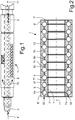
- a bearing assembly 1 of a drive shaft of a drill head is shown.
- the drive shaft is arranged radially inside the bearing assembly 1 and formed as a hollow shaft 3.
- the hollow shaft 3 is supported by the bearing assembly 1 in a rotationally fixed housing 2 and transmits a drive torque from a drive turbine (not shown) on the drill head (not shown).
- a rinsing liquid is introduced according to a flow direction 4, with which the drive turbine is operated.
- a portion of the washing liquid is passed through outlet openings 10 in the hollow shaft 3 in the bearing assembly 1 to cool and lubricate the local rolling bearing, as well as to form a support film in the integrated bearing assembly in the slide bearing.
- Fig. 2 is the bearing assembly 1 of Fig. 1 illustrated, which is formed according to a first embodiment and the hollow shaft 3 in the housing 2 stores.
- this bearing assembly 1 several full-spherical radial thrust ball bearings (4-point bearing) are lined up axially one behind the other to form a stack.
- Each of the 4-point bearings has two radially outer bearing rings 6, 6 * and two radially inner bearing rings 7, 7 *.
- two axially immediately adjacent radially outer bearing rings 6, 6 * together form a radially outer raceway groove 6a and two axially immediately adjacent radially inner bearing rings 7, 7 * together form a radially inner raceway groove 7a.
- the two grooves 6a, 7a of each 4-point bearing are therefore radially divided by a parting plane which is perpendicular to the bearing longitudinal axis 11.
- bearing assembly 1 has axially end one end ring 6 ', 7', which are shorter in comparison to the other bearing rings 6, 7.
- the end rings 6 ', 7' in the second embodiment according to Fig. 3 geometrically and lengthwise identical to the other bearing rings 6, 6 *, 7, 7 * formed.
- the axially longer end rings 6 ', 7' are advantageous in order to reduce the wear and the surface pressure in the end rings 6 ', 7' by applied tilting moments.
- the end rings 6 ', 7' without the in Fig. 3 form half-grooves shown.
- load bearing balls 8 are arranged, which are preferably formed as ceramic balls. Between two of the load-bearing ceramic balls 8 a preferably a slightly smaller separation ball 9 is arranged steel.
- the arrangement of the balls 8, 9 made of steel and ceramic is in Fig. 4 represented in a radial cross section through the bearing assembly 1.
- bearing ceramic balls 8 and separating steel balls 9 are used.
- the radially outer bearing rings 6, 6 *, 6 'and the radially inner bearing rings 7, 7 *, 7' are made of a steel.
- the steel balls 9 may be made of a bearing steel, a stainless bearing steel or a wear-resistant steel.
- the radially outer bearing rings 6, 6 * and the radially inner bearing rings 7, 7 * have axial shoulders 6b and 7b, which end in radial shoulder surfaces 6c, 7c. These radial shoulder surfaces 6c, 7c thus extend axially between the adjacent raceway grooves 6a, 7a.
- the inner diameters Di of the shoulder surfaces 6c of the shoulders 6b on the radially outer bearing rings 6, 6 *, 6 'and the outer diameter Da of the shoulder surfaces 7c of the shoulders 7b on the radially inner bearing rings 7, 7 *, 7' are such that a radial clearance S between the radially opposite shoulder surfaces 6c, 7c is formed. This radial clearance S allows these shoulder surfaces 6c, 7c to perform the function of parallel radial sliding bearing surfaces.
- the radial clearance S between the radially opposite shoulder surfaces 6c, 7c is only a few hundredths of a millimeter.
- the shoulders 7b of the radially inner bearing rings 7, 7 *, 7 'grooves 13 and grooves 12 in the shoulders 6b of the radially outer bearing rings 6, 6 *, 6' are formed to a sufficient flow of the detergent through the To ensure bearing assembly 1.
- These grooves 12, 13 are in the Figures 3 As shown extending in the axial direction, however, it is preferred to form these grooves 12, 13 at an angle to the bearing longitudinal axis 11, not the supporting film of the washing liquid over the entire width of the bearing rings 6, 6 *, 6 ', 7, 7 *, 7 ' to interrupt.
- Fig. 4 shows a ball row of a 4-point bearing of the bearing assembly in the axial plan view.
- the supporting ceramic balls 8 have recognizably on a diameter 8a, which is slightly larger than the diameter 9a of circumferentially adjacent steel balls 9. It is clear from this illustration that the ceramic balls have 8 as Wälzpartner only bearing components made of steel, namely the steel balls 9 and two respectively associated bearing rings 6, 6 *, 6 ', 7, 7 *, 7'.
- the smaller in diameter 9a steel balls 9 must be so much smaller than the ceramic balls 8, that at a maximum load of the bearing assembly 1, these separating steel balls 9 are not to be supported balls.
- the Ceramic balls 8 may consist of all-ceramic or of a carrier material which is coated with ceramic.
- the ceramic material may consist of silicon nitride or zirconium oxide, for example.
- Fig. 4 is also the resulting between the shoulder surfaces 6c and 7c game S shown, since the inner diameter Di of the shoulder surfaces 6c is slightly larger than the outer diameter Da of the shoulder surfaces 7c. Furthermore, the grooves 12 and 13 in the shoulders 6b and 7b can be seen, which favor the flow of the rinsing liquid through the bearing assembly 1.
- At least the shoulder surfaces 6c of the radially outer bearing rings 6, 6 *, 6 'and / or the shoulder surfaces 7c of the radially inner bearing rings 7, 7 *, 7' are provided with a friction and / or wear-reducing coating 14, 15, preferably made of a tribological coating system, which is applied for example by means of the Triondur® process.
- this friction and / or wear-reducing coating 14, 15 are diamond layers.
Landscapes
- Engineering & Computer Science (AREA)
- General Engineering & Computer Science (AREA)
- Mechanical Engineering (AREA)
- Rolling Contact Bearings (AREA)
- Earth Drilling (AREA)
Description
- Die Erfindung betrifft eine Lageranordnung für einen von Spülflüssigkeit durchströmten Bohrkopf einer Tiefbohreinrichtung, mit mehreren radial äußeren und radial inneren Lagerringen, bei der die radial äußeren Lagerringe koaxial über den radial inneren Lagerringen angeordnet sind, bei der radial zwischen den Lagerringen Kugeln angeordnet sind, welche in Laufrillen der Lagerringe abrollen, und bei der die Laufrillen axial beiderseits von Schultern mit parallel zu einer Lagerlängsachse verlaufenden, einander gegenüberliegenden Schulterflächen begrenzt sind. Eine derartige Lageranordnung einer Tiefbohreinrichtung ist aus der
DE 101 62 473 B4 bekannt. Sie umfasst eine größere Anzahl axial hintereinander angeordneter Kugellager, die als 4-Punktkugellager ausgebildet und zu einem Kugellagerstapel zusammengefügt sind. Bei diesen 4-Punktkugellager sind die radial äußeren Lagerringe und die radial inneren Lagerringe geteilt ausgebildet. Es ist bekannt, dass 4-Punktkugellager sowohl Axialkräfte als auch Radialkräfte übertragen können, jedoch wird häufig noch ein Gleitlager axial vor und/oder hinter dem Kugellagerstapel angeordnet, um die 4-Punktkugel-lager von zu großen Radialkräften zu entlasten. Hierdurch ist die Lageranordnung um dieses wenigstens eine Gleitlager axial verlängert, so dass eine solche Lageranordnung in Längsrichtung einen größeren Bauraum erfordert und der minimal mögliche Richtungsänderungsradius für gelenkte Bohrköpfe nachteilig vergrößert ist. -
US 2014/0116780 A1 offenbart die Merkmale des Oberbegriffs von Anspruch 1. - Vor diesem Hintergrund liegt der Erfindung die Aufgabe zugrunde, eine Lageranordnung vorzustellen, die sowohl Radialgleitlager als auch Axialkugellager aufweist, und deren axiale Erstreckung im Wesentlichen einer Lageranordnung ausschließlich aus 4-Punktkugellagern entspricht.
- Die Lösung dieser Aufgabe wird durch eine Lageranordnung mit den Merkmalen des Anspruch1 erreicht. Vorteilhafte Weiterbildungen sind in den Unteransprüchen definiert.
- Demnach geht die Erfindung aus von einer Lageranordnung für einen von Spülflüssigkeit durchströmten Bohrkopf einer Tiefbohreinrichtung, mit mehreren radial äußeren und radial inneren Lagerringen, bei der die radial äußeren Lagerringe koaxial über den radial inneren Lagerringen angeordnet sind, bei der radial zwischen den Lagerringen Kugeln angeordnet sind, welche in Laufrillen der Lagerringe abrollen, und bei der die Laufrillen axial beiderseits von Schultern mit parallel zu einer Lagerlängsachse verlaufenden, einander gegenüberliegenden Schulterflächen begrenzt sind. Bei dieser Lageranordnung ist zur Lösung der gestellten Aufgabe vorgesehen, dass der Innendurchmesser der Schulterflächen der radial äußeren Lagerringe und der Außendurchmesser der Schulterflächen der radial inneren Lagerringe so bemessen sind, dass ein die Funktion von parallelen Radialgleitlagern ergebenes radiales Spiel vorhanden ist.
- Dadurch, dass die Schulterflächen der Schultern beiderseits der Laufrillen der 4-Punkt-kugellager Gleitlager bilden, ist ein kombiniertes Lager geschaffen, welches mehrere Axial-Radial-Wälzlager und Radial-Gleitlager aufweist, dessen Länge genau derjenigen Länge entspricht, welche ein Lagerstapel aufweist, der nur aus 4-Punktkugellagern besteht. Ein gesondertes, gemäß dem Stand der Technik axial hinter oder vor dem Stapel aus 4-Punktkugellagern anzuordnendes Gleitlager wird Kosten sparend nicht benötigt. Außerdem kann durch die Integration der radialen Führung in die Axiallager die axiale Länge der gesamten Lageranordnung vermindert werden. Hierdurch lässt sich der Abstand zwischen dem Bohrkopf und einem Knick für gerichtete Bohrungen verkürzen. Dies ermöglicht vorteilhaft kleinere Radien des Bohrstrangs.
- Gemäß einer vorteilhaften Ausführungsform können die Schulterflächen der radial inneren und/oder der radial äußeren Lagerringe Nuten zum Durchleiten der Spülflüssigkeit aufweisen, sofern der Durchfluss durch die Lageranordnung durch das eingestellte radiale Lagerspiel nicht ausreichen sollte. Vorzugsweise können die Nuten bezüglich der Lagerlängsachse unter einem Winkel angeordnet sein, um nur eine durch die Breite der Nuten bedingte Unterbrechung des Schmierfilms des Gleitlagers zu verursachen.
- Um die Montage eines 4-Punktkugellagers des Kugellagerbereichs der erfindungsgemäßen Lageranordnung zu vereinfachen, können die radial äußeren und/oder radial inneren Lagerringe in einer Ebene geteilt ausgebildet sein, welche senkrecht zur Lagerlängsachse mittig durch die Laufrillen.
- Die Lageranordnung weist mindestens eine Kugelreihe mit den zugehörigen Lagerringen auf. Die axial endseitigen Endringe der Lageranordnung können länger sein, als dies bei 4-Punktkugellagern für Bohrköpfe für vergleichbare Betriebslasten üblich ist, insbesondere zur Vermindung des Verschleißes und der Flächenpressung in dem Radialgleitlager.
- Vorzugsweise ist vorgesehen, dass mehrere Kugelreihen mit dem zugehörigen Lagerringen zu einem Lagerstapel zusammengefügt sind, und dass die Endringe länger ausgebildet sind, als die zwischen diesen Endringen angeordneten Lagerringe.
- Durch die Integration der radialen Gleitlager in die als 4-Punktlager ausgebildeten Axial-Radial-Wälzlager verringert sich der axiale Abstand der radialen Abstützstellen, wodurch das Kippmoment bei gleicher aufgebrachter Kraft ansteigt. Um diesen Effekt zu verringern, kann die Anzahl der Kugelreihen mit den zugehörigen Lagerringen größer sein, als dies bei konventionellen 4-Punktlagern für Bohrköpfe bei vergleichbaren Betriebslasten üblich ist.
- Da die Lageranordnung von einer Spülflüssigkeit durchströmt wird, welche unvermeidlicher Verunreinigungen enthält, die zu einem zu schnellen Verschleiß der Lageranordnung führen, kann vorgesehen sein, dass wenigstens die Schulterflächen der radial äußeren Lagerringe und/oder die Schulterflächen der radial inneren Lagerringe mit einer reibungs- und/oder verschleißmindernden Beschichtung versehen sind, welche vorzugsweise aus einem tribologischen Schichtsystem besteht. Dieses tribologische Schichtsystem kann mittels des Triondur®-Verfahrens aufgebracht sein. Triondur® ist ein eingetragenes Warenzeichen der Anmelderin. Insbesondere kann die reibungs- und/oder verschleißmindernde Beschichtung aus Diamantschichten bestehen.
- Die Erfindung wird nachstehend anhand von in der Zeichnung dargestellten Ausführungsbeispielen weiter erläutert. In dieser Zeichnung zeigt
- Fig. 1
- eine Antriebswelle eines Bohrkopfes mit einer Lageranordnung,
- Fig. 2
- die Lageranordnung gemäß
Fig. 1 im schematischen Längsschnitt gemäß einer ersten Ausführungsform der Erfindung, - Fig. 3
- eine zweite Ausführungsform der Lageranordnung gemäß
Fig. 1 , und - Fig. 4
- einen radialen Querschnitt durch die Lageranordnung der
Figuren 2 und3 . - In
Fig. 1 ist demnach eine Lageranordnung 1 einer Antriebswelle eines Bohrkopfes dargestellt. Die Antriebswelle ist radial innerhalb der Lageranordnung 1 angeordnet und als Hohlwelle 3 ausgebildet. Die Hohlwelle 3 ist mittels der Lageranordnung 1 in einem drehfesten Gehäuse 2 abgestützt und überträgt ein Antriebsdrehmoment von einer Antriebsturbine (nicht dargestellt) auf den Bohrkopf (nicht dargestellt). In die Hohlwelle 3 wird eine Spülflüssigkeit gemäß einer Flussrichtung 4 eingeleitet, mit der die Antriebsturbine betrieben wird. Axial vor der Lageranordnung 1 wird ein Teil der Spülflüssigkeit durch Austrittsöffnungen 10 in der Hohlwelle 3 in die Lageranordnung 1 geleitet, um die dortige Wälzlagerung zu kühlen und zu schmieren, sowie um einen Tragfilm in dem in die Lageranordnung integrierten Gleitlager zu bilden. Mit einem größeren Anteil der Spülflüssigkeit, welcher aus der Hohlwelle 3 im Bereich 5 durch Öffnungen in derselben austritt, wird dann der Bohrkopf gekühlt und geschmiert. Da die Spülflüssigkeit immer etwas verunreinigt ist, gelangen ständig Verunreinigungen in die Lageranordnung 1. - In
Fig. 2 ist die Lageranordnung 1 derFig. 1 dargestellt, welche gemäß einer ersten Ausführungsform ausgebildet ist und die Hohlwelle 3 in dem Gehäuse 2 lagert. Bei dieser Lageranordnung 1 sind mehrere vollkugelige Radial-Axialkugellager (4-Punktlager) axial hintereinander zu einem Stapel aufgereiht. Jedes der 4-Punktlager weist zwei radial äußere Lagerringe 6, 6* und zwei radial innere Lagerringe 7, 7* auf. Jeweils zwei axial unmittelbar benachbarte radial äußere Lagerringe 6, 6* bilden zusammen eine radial äußere Laufrille 6a und jeweils zwei axial unmittelbar benachbarte radial innere Lagerringe 7, 7* bilden zusammen eine radial innere Laufrille 7a. Die beiden Laufrillen 6a, 7a eines jeden 4-Punktlagers sind demnach durch eine Trennebene radial geteilt, welche senkrecht auf der Lagerlängsachse 11 steht. - Die in
Fig. 2 dargestellte Lageranordnung 1 weist axial endseitig jeweils einen Endring 6', 7' auf, die im Vergleich zu den übrigen Lagerringen 6, 7 kürzer sind. Demgegenüber sind die Endringe 6', 7' bei der zweiten Ausführungsform gemäßFig. 3 geometrisch und längenbezogen identisch wie die übrigen Lagerringe 6, 6*, 7, 7* ausgebildet. Die axial längeren Endringe 6', 7' sind vorteilhaft, um den Verschleiß und die Flächenpressung in den Endringen 6', 7' durch aufgebrachte Kippmomente zu verringern. In diesem Fall ist es auch möglich, die Endringe 6', 7' ohne die inFig. 3 dargestellten halben Laufrillen auszubilden. - In den Laufrillen 6a, 7a sind Last tragende Kugeln 8 angeordnet, die vorzugsweise als Keramikkugeln ausgebildet sind. Zwischen zwei der last tragenden Keramikkugeln 8 ist eine vorzugsweise eine etwas kleinere Trennkugel 9 aus Stahl angeordnet. Die Anordnung der Kugeln 8, 9 aus Stahl und Keramik ist in
Fig. 4 in einem radialen Querschnitt durch die Lageranordnung 1 dargestellt. In jedem einzelnen 4-Punktlager der Lageranordnung 1 sind dabei tragende Keramikkugeln 8 und trennende Stahlkugeln 9 eingesetzt. Die radial äußeren Lagerringe 6, 6*, 6' und die radial inneren Lagerringe 7, 7*, 7' bestehen aus einem Stahl. Die Stahlkugeln 9 können aus einem Wälzlagerstahl, aus einem rostfreien Wälzlagerstahl oder aus einem verschleißfesten Stahl gefertigt sein. - Die radial äußeren Lagerringe 6, 6* und die radial inneren Lagerringe 7, 7* weisen axiale Schultern 6b bzw. 7b auf, welche in radialen Schulterflächen 6c, 7c enden. Diese radialen Schulterflächen 6c, 7c erstrecken sich demnach axial zwischen den benachbarten Laufrillen 6a, 7a. Die inneren Durchmesser Di der Schulterflächen 6c der Schultern 6b an den radial äußeren Lagerringen 6, 6*, 6' und die Außendurchmesser Da der Schulterflächen 7c der Schultern 7b an den radial inneren Lagerringen 7, 7*, 7' sind so bemessen, dass ein radiales Spiel S zwischen den radial gegenüber angeordneten Schulterflächen 6c, 7c gebildet ist. Dieses radiale Spiel S ermöglicht es diesen Schulterflächen 6c, 7c die Funktion von parallelen Radialgleitlagerflächen auszuüben. Das radiale Spiel S zwischen den radial gegenüber angeordneten Schulterflächen 6c, 7c beträgt nur wenige Hundertstel Millimeter. In diesen Ausführungsbeispielen sind in den Schultern 7b der radial inneren Lagerringe 7, 7*, 7' Nuten 13 und Nuten 12 in den Schultern 6b der radial äußeren Lagerringe 6, 6*, 6' ausgebildet sind, um einen ausreichenden Durchfluss des Spülmittels durch die Lageranordnung 1 zu gewährleisten. Diese Nuten 12, 13 sind in den
Figuren 3 als in Axialrichtung verlaufend dargestellt, jedoch wird es bevorzugt, diese Nuten 12, 13 unter einem Winkel zur Lagerlängsachse 11 auszubilden, um den Tragfilm der Spülflüssigkeit nicht über die gesamte Breite der Lagerringe 6, 6*, 6', 7, 7*, 7' zu unterbrechen. -
Fig. 4 zeigt eine Kugelreihe eines 4-Punktlagers der Lageranordnung in der axialen Draufsicht. Die tragenden Keramikkugeln 8 weisen erkennbar einen Durchmesser 8a auf, der geringfügig größer ist als der Durchmesser 9a der umfangsbezogen benachbarten Stahlkugeln 9. Es wird aus dieser Darstellung deutlich, dass die Keramikkugeln 8 als Wälzpartner nur Lagerbestandteile aus Stahl haben, nämlich die Stahlkugeln 9 und die beiden jeweils zugeordneten Lagerringe 6, 6*, 6', 7, 7*, 7'. Die im Durchmesser 9a kleineren Stahlkugeln 9 müssen um so viel kleiner als die Keramikkugeln 8 sein, dass bei einer Maximalbelastung der Lageranordnung 1 diese trennenden Stahlkugeln 9 nicht zu tragenden Kugeln werden. Die Keramikkugeln 8 können aus Vollkeramik oder aus einem Trägermaterial, das mit Keramik beschichtet ist, bestehen. Das Keramikmaterial kann beispielsweise aus Siliziumnitrid oder Zirkoniumoxid bestehen. - In
Fig. 4 ist auch das sich zwischen den Schulterflächen 6c und 7c ergebende Spiel S dargestellt, da der Innendurchmesser Di der Schulterflächen 6c geringfügig größer ist als der Außendurchmesser Da der Schulterflächen 7c. Des Weiteren sind auch die Nuten 12 und 13 in den Schultern 6b und 7b erkennbar, welche den Durchfluss der Spülflüssigkeit durch die Lageranordnung 1 begünstigen. - Wenigstens die Schulterflächen 6c der radial äußeren Lagerringe 6, 6*, 6' und/oder die Schulterflächen 7c der radial inneren Lagerringe 7, 7*, 7' sind mit einer reibungs- und/oder verschleißmindernden Beschichtung 14, 15 versehen, die vorzugsweise aus einem tribologischen Schichtsystem besteht, das beispielsweise mittels des Triondur®-Verfahrens aufgebracht wird. Vorzugsweise, aber nicht ausschließlich, handelt es sich bei dieser reibungs- und/oder verschleißmindernden Beschichtung 14, 15 um Diamantschichten.
-
- 1
- Lageranordnung
- 2
- Gehäuse
- 3
- Hohlwelle, Antriebswelle
- 4
- Flussrichtung der Spülflüssigkeit
- 5
- Austritt der Spülflüssigkeit
- 6, 6*
- Radial äußere Lagerringe
- 6a
- Laufrillen in den äußeren Lagerringen 6, 6*
- 6b
- Schultern an den äußeren Lagerringen 6, 6*, 6'
- 6c
- Schulterflächen an den Schultern 6b
- 6'
- Radial äußerer Endring
- 7, 7*
- Radial innere Lagerringe
- 7a
- Laufrillen in den inneren Lagerringen 7, 7*
- 7b
- Schultern an den inneren Lagerringen 7, 7*, 7'
- 7c
- Schulterflächen an den Schultern 7b
- 7'
- Radial innerer Endring
- 8
- Tragende Keramikkugeln
- 8a
- Durchmesser der tragenden Keramikkugeln
- 9
- Trennende Stahlkugeln
- 9a
- Durchmesser der trennenden Stahlkugeln
- 10
- Austrittsöffnungen in der Hohlwelle für die Spülflüssigkeit
- 11
- Lagerlängsachse
- 12
- Nuten in den Schultern 6b
- 13
- Nuten in den Schultern 7b
- 14
- Beschichtung
- 15
- Beschichtung
- Di
- Innendurchmesser der Schulterflächen 6c
- Da
- Außendurchmesser der Schulterflächen 7c
- S
- Radiales Spiel zwischen den Schulterflächen 6c und 7c
Claims (10)
- Lageranordnung (1) für einen von Spülflüssigkeit durchströmten Bohrkopf einer Tiefbohreinrichtung, mit mehreren radial äußeren und radial inneren Lagerringen (6, 6*, 6', 7, 7*, 7'), bei der die radial äußeren Lagerringe (6, 6*, 6') koaxial über den radial inneren Lagerringen (7, 7*, 7') angeordnet sind, bei der radial zwischen den Lagerringen (6, 6*, 6', 7, 7*, 7') Kugeln (8, 9) angeordnet sind, welche in Laufrillen (6a, 7a) der Lagerringe (6, 6*, 6', 7, 7*, 7') abrollen, und bei der die Laufrillen (6a, 7a) axial beiderseits von Schultern (6b, 7b) mit parallel zu einer Lagerlängsachse (11) verlaufenden, einander gegenüberliegenden Schulterflächen (6c, 7c) begrenzt sind, dadurch gekennzeichnet, dass der Innendurchmesser (Di) der Schulterflächen (6c, 7c) der radial äußeren Lagerringe (6, 6*, 6') und der Außendurchmesser (Da) der Schulterflächen (7c) der radial inneren Lagerringe (7, 7*, 7') so bemessen sind, dass ein die Funktion von parallelen Radialgleitlagern ergebenes radiales Spiel (S) vorhanden ist.
- Lageranordnung nach Anspruch 1, dadurch gekennzeichnet, dass die Schulterflächen (6c, 7c) der radial inneren und/oder der radial äußeren Lagerringe (6, 6*, 6', 7, 7*, 7') Nuten (12, 13) zum Durchleiten der Spülflüssigkeit aufweisen.
- Lageranordnung nach Anspruch 1 oder 2, dadurch gekennzeichnet, dass jeder radial äußere und/oder radial innere Lagerring (6, 6*, 6', 7, 7*, 7') in einer Ebene senkrecht zur Lagerlängsachse (11) mittig durch die Laufrillen (6a, 7a) geteilt ist und ein 4-Punktlager bildet.
- Lageranordnung nach Anspruch 1, 2 oder 3, dadurch gekennzeichnet, dass die Lageranordnung (1) mindestens eine Kugelreihe mit den zugehörigen Lagerringen (6, 6*, 6', 7, 7*, 7') aufweist, und dass axial endseitige Endringe (6', 7') axial länger ausgeführt sind, als dies bei 4-Punktlagern für Bohrköpfe bei vergleichbaren Betriebslasten üblich ist.
- Lageranordnung nach einem der Ansprüche 1 bis 3, dadurch gekennzeichnet, dass mehrere Kugelreihen mit dem zugehörigen Lagerringen (6, 6*, 6', 7, 7*, 7') zu einem Lagerstapel zusammengefügt sind, und dass die Endringe (6', 7') länger ausgebildet sind, als die zwischen diesen Endringen (6', 7') angeordneten Lagerringe (6, 6*, 6', 7, 7*, 7').
- Lageranordnung nach einem der Ansprüche 1 bis 5, dadurch gekennzeichnet, dass die Anzahl der Kugelreihen mit den zugehörigen Lagerringen (6, 6*, 6', 7, 7*, 7') größer ist, als dies bei 4-Punklagern für Bohrköpfe bei vergleichbaren Betriebslasten üblich ist.
- Lageranordnung nach einem der Ansprüche 1 bis 6, dadurch gekennzeichnet, dass die Schulterflächen (6c) der radial äußeren Lagerringe (6, 6*, 6') und/oder die Schulterflächen (7c) der radial inneren Lagerringe (7, 7*, 7') mit einer reibungsmindernden und/oder verschleißmindernden Beschichtung (14, 15) versehen sind.
- Lageranordnung nach Anspruch 7, dadurch gekennzeichnet, dass die reibungs- und/oder verschleißmindernde Beschichtung (14, 15) aus einem tribologischen Schichtsystem besteht.
- Lageranordnung nach Anspruch 8, dadurch gekennzeichnet, dass das tribologische Schichtsystem mittels des Triondur®-Verfahrens aufgebracht ist.
- Lageranordnung nach einem der Ansprüche 7 bis 9, dadurch gekennzeichnet, dass die reibungs- und/oder verschleißmindernde Beschichtung (14, 15) Diamantschichten besteht.
Applications Claiming Priority (2)
| Application Number | Priority Date | Filing Date | Title |
|---|---|---|---|
| DE102014220792.4A DE102014220792A1 (de) | 2014-10-14 | 2014-10-14 | Lageranordnung für eine Tiefbohreinrichtung |
| PCT/DE2015/200451 WO2016058602A1 (de) | 2014-10-14 | 2015-09-03 | Lageranordnung für eine tiefbohreinrichtung |
Publications (2)
| Publication Number | Publication Date |
|---|---|
| EP3207267A1 EP3207267A1 (de) | 2017-08-23 |
| EP3207267B1 true EP3207267B1 (de) | 2018-08-29 |
Family
ID=54476625
Family Applications (1)
| Application Number | Title | Priority Date | Filing Date |
|---|---|---|---|
| EP15790447.5A Active EP3207267B1 (de) | 2014-10-14 | 2015-09-03 | Lageranordnung für eine tiefbohreinrichtung |
Country Status (9)
| Country | Link |
|---|---|
| US (1) | US10197100B2 (de) |
| EP (1) | EP3207267B1 (de) |
| CN (1) | CN106795912B (de) |
| BR (1) | BR112017006822B1 (de) |
| CA (1) | CA2959462C (de) |
| DE (1) | DE102014220792A1 (de) |
| MX (1) | MX374815B (de) |
| RU (1) | RU2017112751A (de) |
| WO (1) | WO2016058602A1 (de) |
Families Citing this family (3)
| Publication number | Priority date | Publication date | Assignee | Title |
|---|---|---|---|---|
| JPWO2017082421A1 (ja) * | 2015-11-13 | 2018-08-30 | 日本精工株式会社 | 多列玉軸受 |
| WO2018041124A1 (zh) * | 2016-08-31 | 2018-03-08 | 马鞍山支点传孚智能摩擦工业研究院有限公司 | 轴承 |
| CN108518414A (zh) * | 2018-05-30 | 2018-09-11 | 长江大学 | 一种大通道可钻止推轴承 |
Family Cites Families (8)
| Publication number | Priority date | Publication date | Assignee | Title |
|---|---|---|---|---|
| DE1907632U (de) | 1964-10-09 | 1964-12-31 | Dietmar Wagner | Gleit-waelzlager. |
| DE2527237C3 (de) | 1975-06-19 | 1980-03-20 | Vsesojuznyj Nautschno-Issledovatelskij Institut Burovoj Techniki, Moskau | Axiallagerung für hydraulische Bohrturbinen |
| DE10162473B4 (de) | 2001-12-19 | 2005-12-01 | Fag Kugelfischer Ag & Co. Ohg | Wälzlager in Tiefbohreinrichtung |
| JP2008243694A (ja) * | 2007-03-28 | 2008-10-09 | Jtekt Corp | X線管用転がり軸受およびx線管装置 |
| CN201265597Y (zh) * | 2008-08-13 | 2009-07-01 | 王庆林 | 石油钻井机上用的一种硬质合金轴承 |
| US8414448B2 (en) * | 2011-08-31 | 2013-04-09 | General Electric Company | Gear system for wind turbine |
| DE102012214212A1 (de) * | 2011-09-01 | 2013-03-07 | Schaeffler Technologies AG & Co. KG | Lagereinrichtung und Drehmomentübertragungseinrichtung |
| US9045941B2 (en) * | 2012-10-25 | 2015-06-02 | Scientific Drilling International, Inc. | Hybrid bearings for downhole motors |
-
2014
- 2014-10-14 DE DE102014220792.4A patent/DE102014220792A1/de not_active Withdrawn
-
2015
- 2015-09-03 EP EP15790447.5A patent/EP3207267B1/de active Active
- 2015-09-03 US US15/513,746 patent/US10197100B2/en not_active Expired - Fee Related
- 2015-09-03 CN CN201580055396.2A patent/CN106795912B/zh active Active
- 2015-09-03 WO PCT/DE2015/200451 patent/WO2016058602A1/de not_active Ceased
- 2015-09-03 CA CA2959462A patent/CA2959462C/en active Active
- 2015-09-03 BR BR112017006822-2A patent/BR112017006822B1/pt active IP Right Grant
- 2015-09-03 RU RU2017112751A patent/RU2017112751A/ru not_active Application Discontinuation
- 2015-09-03 MX MX2017004355A patent/MX374815B/es active IP Right Grant
Also Published As
| Publication number | Publication date |
|---|---|
| CN106795912A (zh) | 2017-05-31 |
| DE102014220792A1 (de) | 2016-04-14 |
| US10197100B2 (en) | 2019-02-05 |
| CA2959462A1 (en) | 2016-04-21 |
| MX2017004355A (es) | 2017-07-04 |
| CA2959462C (en) | 2023-03-07 |
| CN106795912B (zh) | 2019-04-12 |
| BR112017006822B1 (pt) | 2021-11-23 |
| EP3207267A1 (de) | 2017-08-23 |
| WO2016058602A1 (de) | 2016-04-21 |
| MX374815B (es) | 2025-03-06 |
| US20170284469A1 (en) | 2017-10-05 |
| RU2017112751A (ru) | 2018-10-15 |
| BR112017006822A2 (pt) | 2018-03-27 |
Similar Documents
| Publication | Publication Date | Title |
|---|---|---|
| DE102012211891B4 (de) | Wälzlager für einen Turbolader | |
| EP2994657B1 (de) | Fettgeschmiertes schrägkugellager | |
| EP3284966A1 (de) | Lageranordnung, insbesondere für eine strömungsmaschine, und strömungsmaschine mit einer derartigen lageranordnung | |
| EP2146113B1 (de) | Reibringgetriebe mit einem Reibring und Verfahren zum Herstellen eines Reibkegels | |
| WO2011018489A1 (de) | Käfigsegment für einen kunststoffkäfig eines wälzlagers und wälzlager mit einem solchen käfigsegment | |
| EP1837536A2 (de) | Schrägrollenlager | |
| DE102015215296B4 (de) | Lageranordnung und Lagerring zum drehbeweglichen Lagern eines ersten Bauteils gegenüber einem zweiten Bauteil sowie Schraubenkompressor mit der Lageranordnung oder dem Lagerring | |
| EP3207267B1 (de) | Lageranordnung für eine tiefbohreinrichtung | |
| EP3019760B1 (de) | Stützlagerung, insbesondere laufrolle | |
| DE102004039641B4 (de) | Längsverschiebeeinheit mit Käfigsicherung | |
| DE102013218434B4 (de) | Lagerung | |
| WO2011018491A1 (de) | Käfigsegment für einen kunststoffkäfig eines wälzlagers und wälzlager mit einem solchen käfigsegment | |
| DE102012016983B4 (de) | Wälzlager mit Wälzlagerkäfig | |
| DE102007033905A1 (de) | Vollkugeliges Schrägkugellager | |
| DE102014212620B4 (de) | Radialwälzlager eines Abgasturboladers | |
| DE102014219574B4 (de) | Wälzlager | |
| DE102011088690A1 (de) | Wälzlagerkäfig und Wälzlager | |
| DE19851897B4 (de) | Kegelrollenlager | |
| EP1554477A2 (de) | Gleitlager für eine welle eines abgasturboladers | |
| DE102010055091A1 (de) | Lagerungsanordnung einer Kurbelwelle an einem Lagerteil | |
| DE102012207528B3 (de) | Wälzlager | |
| DE102009013038B4 (de) | Tripodegelenkrolle und Tripodegelenk | |
| DE102009041747A1 (de) | Wälzlager | |
| EP3014079B1 (de) | Verstellbare nockenwelle | |
| EP2997272B1 (de) | Kippsegment und radialgleitlager |
Legal Events
| Date | Code | Title | Description |
|---|---|---|---|
| PUAI | Public reference made under article 153(3) epc to a published international application that has entered the european phase |
Free format text: ORIGINAL CODE: 0009012 |
|
| 17P | Request for examination filed |
Effective date: 20170515 |
|
| AK | Designated contracting states |
Kind code of ref document: A1 Designated state(s): AL AT BE BG CH CY CZ DE DK EE ES FI FR GB GR HR HU IE IS IT LI LT LU LV MC MK MT NL NO PL PT RO RS SE SI SK SM TR |
|
| AX | Request for extension of the european patent |
Extension state: BA ME |
|
| DAV | Request for validation of the european patent (deleted) | ||
| DAX | Request for extension of the european patent (deleted) | ||
| REG | Reference to a national code |
Ref country code: DE Ref legal event code: R079 Ref document number: 502015005735 Country of ref document: DE Free format text: PREVIOUS MAIN CLASS: F16C0033600000 Ipc: F16C0017020000 |
|
| GRAP | Despatch of communication of intention to grant a patent |
Free format text: ORIGINAL CODE: EPIDOSNIGR1 |
|
| RIC1 | Information provided on ipc code assigned before grant |
Ipc: F16C 19/52 20060101ALI20180302BHEP Ipc: F16C 17/02 20060101AFI20180302BHEP Ipc: F16C 21/00 20060101ALI20180302BHEP Ipc: F16C 33/60 20060101ALI20180302BHEP Ipc: F16C 39/02 20060101ALI20180302BHEP Ipc: F16C 19/18 20060101ALI20180302BHEP Ipc: F16C 33/37 20060101ALI20180302BHEP |
|
| INTG | Intention to grant announced |
Effective date: 20180406 |
|
| GRAS | Grant fee paid |
Free format text: ORIGINAL CODE: EPIDOSNIGR3 |
|
| GRAA | (expected) grant |
Free format text: ORIGINAL CODE: 0009210 |
|
| AK | Designated contracting states |
Kind code of ref document: B1 Designated state(s): AL AT BE BG CH CY CZ DE DK EE ES FI FR GB GR HR HU IE IS IT LI LT LU LV MC MK MT NL NO PL PT RO RS SE SI SK SM TR |
|
| REG | Reference to a national code |
Ref country code: GB Ref legal event code: FG4D Free format text: NOT ENGLISH |
|
| REG | Reference to a national code |
Ref country code: CH Ref legal event code: EP |
|
| REG | Reference to a national code |
Ref country code: AT Ref legal event code: REF Ref document number: 1035479 Country of ref document: AT Kind code of ref document: T Effective date: 20180915 |
|
| REG | Reference to a national code |
Ref country code: IE Ref legal event code: FG4D Free format text: LANGUAGE OF EP DOCUMENT: GERMAN |
|
| REG | Reference to a national code |
Ref country code: DE Ref legal event code: R096 Ref document number: 502015005735 Country of ref document: DE |
|
| REG | Reference to a national code |
Ref country code: NL Ref legal event code: MP Effective date: 20180829 |
|
| REG | Reference to a national code |
Ref country code: LT Ref legal event code: MG4D |
|
| PG25 | Lapsed in a contracting state [announced via postgrant information from national office to epo] |
Ref country code: BG Free format text: LAPSE BECAUSE OF FAILURE TO SUBMIT A TRANSLATION OF THE DESCRIPTION OR TO PAY THE FEE WITHIN THE PRESCRIBED TIME-LIMIT Effective date: 20181129 Ref country code: NL Free format text: LAPSE BECAUSE OF FAILURE TO SUBMIT A TRANSLATION OF THE DESCRIPTION OR TO PAY THE FEE WITHIN THE PRESCRIBED TIME-LIMIT Effective date: 20180829 Ref country code: IS Free format text: LAPSE BECAUSE OF FAILURE TO SUBMIT A TRANSLATION OF THE DESCRIPTION OR TO PAY THE FEE WITHIN THE PRESCRIBED TIME-LIMIT Effective date: 20181229 Ref country code: RS Free format text: LAPSE BECAUSE OF FAILURE TO SUBMIT A TRANSLATION OF THE DESCRIPTION OR TO PAY THE FEE WITHIN THE PRESCRIBED TIME-LIMIT Effective date: 20180829 Ref country code: LT Free format text: LAPSE BECAUSE OF FAILURE TO SUBMIT A TRANSLATION OF THE DESCRIPTION OR TO PAY THE FEE WITHIN THE PRESCRIBED TIME-LIMIT Effective date: 20180829 Ref country code: GR Free format text: LAPSE BECAUSE OF FAILURE TO SUBMIT A TRANSLATION OF THE DESCRIPTION OR TO PAY THE FEE WITHIN THE PRESCRIBED TIME-LIMIT Effective date: 20181130 Ref country code: FI Free format text: LAPSE BECAUSE OF FAILURE TO SUBMIT A TRANSLATION OF THE DESCRIPTION OR TO PAY THE FEE WITHIN THE PRESCRIBED TIME-LIMIT Effective date: 20180829 Ref country code: SE Free format text: LAPSE BECAUSE OF FAILURE TO SUBMIT A TRANSLATION OF THE DESCRIPTION OR TO PAY THE FEE WITHIN THE PRESCRIBED TIME-LIMIT Effective date: 20180829 |
|
| REG | Reference to a national code |
Ref country code: NO Ref legal event code: T2 Effective date: 20180829 |
|
| PG25 | Lapsed in a contracting state [announced via postgrant information from national office to epo] |
Ref country code: AL Free format text: LAPSE BECAUSE OF FAILURE TO SUBMIT A TRANSLATION OF THE DESCRIPTION OR TO PAY THE FEE WITHIN THE PRESCRIBED TIME-LIMIT Effective date: 20180829 Ref country code: LV Free format text: LAPSE BECAUSE OF FAILURE TO SUBMIT A TRANSLATION OF THE DESCRIPTION OR TO PAY THE FEE WITHIN THE PRESCRIBED TIME-LIMIT Effective date: 20180829 Ref country code: HR Free format text: LAPSE BECAUSE OF FAILURE TO SUBMIT A TRANSLATION OF THE DESCRIPTION OR TO PAY THE FEE WITHIN THE PRESCRIBED TIME-LIMIT Effective date: 20180829 |
|
| PG25 | Lapsed in a contracting state [announced via postgrant information from national office to epo] |
Ref country code: EE Free format text: LAPSE BECAUSE OF FAILURE TO SUBMIT A TRANSLATION OF THE DESCRIPTION OR TO PAY THE FEE WITHIN THE PRESCRIBED TIME-LIMIT Effective date: 20180829 Ref country code: PL Free format text: LAPSE BECAUSE OF FAILURE TO SUBMIT A TRANSLATION OF THE DESCRIPTION OR TO PAY THE FEE WITHIN THE PRESCRIBED TIME-LIMIT Effective date: 20180829 Ref country code: CZ Free format text: LAPSE BECAUSE OF FAILURE TO SUBMIT A TRANSLATION OF THE DESCRIPTION OR TO PAY THE FEE WITHIN THE PRESCRIBED TIME-LIMIT Effective date: 20180829 Ref country code: RO Free format text: LAPSE BECAUSE OF FAILURE TO SUBMIT A TRANSLATION OF THE DESCRIPTION OR TO PAY THE FEE WITHIN THE PRESCRIBED TIME-LIMIT Effective date: 20180829 Ref country code: IT Free format text: LAPSE BECAUSE OF FAILURE TO SUBMIT A TRANSLATION OF THE DESCRIPTION OR TO PAY THE FEE WITHIN THE PRESCRIBED TIME-LIMIT Effective date: 20180829 |
|
| REG | Reference to a national code |
Ref country code: CH Ref legal event code: PL |
|
| PG25 | Lapsed in a contracting state [announced via postgrant information from national office to epo] |
Ref country code: SK Free format text: LAPSE BECAUSE OF FAILURE TO SUBMIT A TRANSLATION OF THE DESCRIPTION OR TO PAY THE FEE WITHIN THE PRESCRIBED TIME-LIMIT Effective date: 20180829 Ref country code: SM Free format text: LAPSE BECAUSE OF FAILURE TO SUBMIT A TRANSLATION OF THE DESCRIPTION OR TO PAY THE FEE WITHIN THE PRESCRIBED TIME-LIMIT Effective date: 20180829 Ref country code: DK Free format text: LAPSE BECAUSE OF FAILURE TO SUBMIT A TRANSLATION OF THE DESCRIPTION OR TO PAY THE FEE WITHIN THE PRESCRIBED TIME-LIMIT Effective date: 20180829 |
|
| REG | Reference to a national code |
Ref country code: DE Ref legal event code: R097 Ref document number: 502015005735 Country of ref document: DE |
|
| REG | Reference to a national code |
Ref country code: BE Ref legal event code: MM Effective date: 20180930 |
|
| REG | Reference to a national code |
Ref country code: IE Ref legal event code: MM4A |
|
| PG25 | Lapsed in a contracting state [announced via postgrant information from national office to epo] |
Ref country code: LU Free format text: LAPSE BECAUSE OF NON-PAYMENT OF DUE FEES Effective date: 20180903 Ref country code: MC Free format text: LAPSE BECAUSE OF FAILURE TO SUBMIT A TRANSLATION OF THE DESCRIPTION OR TO PAY THE FEE WITHIN THE PRESCRIBED TIME-LIMIT Effective date: 20180829 |
|
| PLBE | No opposition filed within time limit |
Free format text: ORIGINAL CODE: 0009261 |
|
| STAA | Information on the status of an ep patent application or granted ep patent |
Free format text: STATUS: NO OPPOSITION FILED WITHIN TIME LIMIT |
|
| PG25 | Lapsed in a contracting state [announced via postgrant information from national office to epo] |
Ref country code: IE Free format text: LAPSE BECAUSE OF NON-PAYMENT OF DUE FEES Effective date: 20180903 Ref country code: ES Free format text: LAPSE BECAUSE OF FAILURE TO SUBMIT A TRANSLATION OF THE DESCRIPTION OR TO PAY THE FEE WITHIN THE PRESCRIBED TIME-LIMIT Effective date: 20180829 |
|
| 26N | No opposition filed |
Effective date: 20190531 |
|
| PG25 | Lapsed in a contracting state [announced via postgrant information from national office to epo] |
Ref country code: CH Free format text: LAPSE BECAUSE OF NON-PAYMENT OF DUE FEES Effective date: 20180930 Ref country code: SI Free format text: LAPSE BECAUSE OF FAILURE TO SUBMIT A TRANSLATION OF THE DESCRIPTION OR TO PAY THE FEE WITHIN THE PRESCRIBED TIME-LIMIT Effective date: 20180829 Ref country code: BE Free format text: LAPSE BECAUSE OF NON-PAYMENT OF DUE FEES Effective date: 20180930 Ref country code: FR Free format text: LAPSE BECAUSE OF NON-PAYMENT OF DUE FEES Effective date: 20181029 Ref country code: LI Free format text: LAPSE BECAUSE OF NON-PAYMENT OF DUE FEES Effective date: 20180930 |
|
| PG25 | Lapsed in a contracting state [announced via postgrant information from national office to epo] |
Ref country code: MT Free format text: LAPSE BECAUSE OF FAILURE TO SUBMIT A TRANSLATION OF THE DESCRIPTION OR TO PAY THE FEE WITHIN THE PRESCRIBED TIME-LIMIT Effective date: 20180829 |
|
| PG25 | Lapsed in a contracting state [announced via postgrant information from national office to epo] |
Ref country code: TR Free format text: LAPSE BECAUSE OF FAILURE TO SUBMIT A TRANSLATION OF THE DESCRIPTION OR TO PAY THE FEE WITHIN THE PRESCRIBED TIME-LIMIT Effective date: 20180829 |
|
| PG25 | Lapsed in a contracting state [announced via postgrant information from national office to epo] |
Ref country code: PT Free format text: LAPSE BECAUSE OF FAILURE TO SUBMIT A TRANSLATION OF THE DESCRIPTION OR TO PAY THE FEE WITHIN THE PRESCRIBED TIME-LIMIT Effective date: 20180829 |
|
| PG25 | Lapsed in a contracting state [announced via postgrant information from national office to epo] |
Ref country code: CY Free format text: LAPSE BECAUSE OF FAILURE TO SUBMIT A TRANSLATION OF THE DESCRIPTION OR TO PAY THE FEE WITHIN THE PRESCRIBED TIME-LIMIT Effective date: 20180829 Ref country code: HU Free format text: LAPSE BECAUSE OF FAILURE TO SUBMIT A TRANSLATION OF THE DESCRIPTION OR TO PAY THE FEE WITHIN THE PRESCRIBED TIME-LIMIT; INVALID AB INITIO Effective date: 20150903 Ref country code: MK Free format text: LAPSE BECAUSE OF NON-PAYMENT OF DUE FEES Effective date: 20180829 |
|
| REG | Reference to a national code |
Ref country code: AT Ref legal event code: MM01 Ref document number: 1035479 Country of ref document: AT Kind code of ref document: T Effective date: 20200903 |
|
| PG25 | Lapsed in a contracting state [announced via postgrant information from national office to epo] |
Ref country code: AT Free format text: LAPSE BECAUSE OF NON-PAYMENT OF DUE FEES Effective date: 20200903 |
|
| P01 | Opt-out of the competence of the unified patent court (upc) registered |
Effective date: 20230523 |
|
| PGFP | Annual fee paid to national office [announced via postgrant information from national office to epo] |
Ref country code: DE Payment date: 20231121 Year of fee payment: 9 |
|
| PGFP | Annual fee paid to national office [announced via postgrant information from national office to epo] |
Ref country code: GB Payment date: 20240920 Year of fee payment: 10 |
|
| PGFP | Annual fee paid to national office [announced via postgrant information from national office to epo] |
Ref country code: NO Payment date: 20240923 Year of fee payment: 10 |
|
| REG | Reference to a national code |
Ref country code: DE Ref legal event code: R119 Ref document number: 502015005735 Country of ref document: DE |
|
| PG25 | Lapsed in a contracting state [announced via postgrant information from national office to epo] |
Ref country code: DE Free format text: LAPSE BECAUSE OF NON-PAYMENT OF DUE FEES Effective date: 20250401 |