EP3207302B1 - Dispositif de retenue pour une tôle-témoin - Google Patents
Dispositif de retenue pour une tôle-témoin Download PDFInfo
- Publication number
- EP3207302B1 EP3207302B1 EP15781345.2A EP15781345A EP3207302B1 EP 3207302 B1 EP3207302 B1 EP 3207302B1 EP 15781345 A EP15781345 A EP 15781345A EP 3207302 B1 EP3207302 B1 EP 3207302B1
- Authority
- EP
- European Patent Office
- Prior art keywords
- pushbutton
- holding device
- arrangement
- handle
- user
- Prior art date
- Legal status (The legal status is an assumption and is not a legal conclusion. Google has not performed a legal analysis and makes no representation as to the accuracy of the status listed.)
- Active
Links
Images


Classifications
-
- B—PERFORMING OPERATIONS; TRANSPORTING
- B21—MECHANICAL METAL-WORKING WITHOUT ESSENTIALLY REMOVING MATERIAL; PUNCHING METAL
- B21J—FORGING; HAMMERING; PRESSING METAL; RIVETING; FORGE FURNACES
- B21J15/00—Riveting
- B21J15/10—Riveting machines
-
- B—PERFORMING OPERATIONS; TRANSPORTING
- B21—MECHANICAL METAL-WORKING WITHOUT ESSENTIALLY REMOVING MATERIAL; PUNCHING METAL
- B21J—FORGING; HAMMERING; PRESSING METAL; RIVETING; FORGE FURNACES
- B21J15/00—Riveting
- B21J15/38—Accessories for use in connection with riveting, e.g. pliers for upsetting; Hand tools for riveting
- B21J15/42—Special clamping devices for workpieces to be riveted together, e.g. operating through the rivet holes
-
- B—PERFORMING OPERATIONS; TRANSPORTING
- B21—MECHANICAL METAL-WORKING WITHOUT ESSENTIALLY REMOVING MATERIAL; PUNCHING METAL
- B21D—WORKING OR PROCESSING OF SHEET METAL OR METAL TUBES, RODS OR PROFILES WITHOUT ESSENTIALLY REMOVING MATERIAL; PUNCHING METAL
- B21D43/00—Feeding, positioning or storing devices combined with, or arranged in, or specially adapted for use in connection with, apparatus for working or processing sheet metal, metal tubes or metal profiles; Associations therewith of cutting devices
-
- B—PERFORMING OPERATIONS; TRANSPORTING
- B21—MECHANICAL METAL-WORKING WITHOUT ESSENTIALLY REMOVING MATERIAL; PUNCHING METAL
- B21D—WORKING OR PROCESSING OF SHEET METAL OR METAL TUBES, RODS OR PROFILES WITHOUT ESSENTIALLY REMOVING MATERIAL; PUNCHING METAL
- B21D55/00—Safety devices protecting the machine or the operator, specially adapted for apparatus or machines dealt with in this subclass
-
- B—PERFORMING OPERATIONS; TRANSPORTING
- B21—MECHANICAL METAL-WORKING WITHOUT ESSENTIALLY REMOVING MATERIAL; PUNCHING METAL
- B21J—FORGING; HAMMERING; PRESSING METAL; RIVETING; FORGE FURNACES
- B21J15/00—Riveting
- B21J15/10—Riveting machines
- B21J15/28—Control devices specially adapted to riveting machines not restricted to one of the preceding subgroups
-
- B—PERFORMING OPERATIONS; TRANSPORTING
- B23—MACHINE TOOLS; METAL-WORKING NOT OTHERWISE PROVIDED FOR
- B23Q—DETAILS, COMPONENTS, OR ACCESSORIES FOR MACHINE TOOLS, e.g. ARRANGEMENTS FOR COPYING OR CONTROLLING; MACHINE TOOLS IN GENERAL CHARACTERISED BY THE CONSTRUCTION OF PARTICULAR DETAILS OR COMPONENTS; COMBINATIONS OR ASSOCIATIONS OF METAL-WORKING MACHINES, NOT DIRECTED TO A PARTICULAR RESULT
- B23Q7/00—Arrangements for handling work specially combined with or arranged in, or specially adapted for use in connection with, machine tools, e.g. for conveying, loading, positioning, discharging, sorting
- B23Q7/04—Arrangements for handling work specially combined with or arranged in, or specially adapted for use in connection with, machine tools, e.g. for conveying, loading, positioning, discharging, sorting by means of grippers
-
- B—PERFORMING OPERATIONS; TRANSPORTING
- B25—HAND TOOLS; PORTABLE POWER-DRIVEN TOOLS; MANIPULATORS
- B25B—TOOLS OR BENCH DEVICES NOT OTHERWISE PROVIDED FOR, FOR FASTENING, CONNECTING, DISENGAGING, OR HOLDING
- B25B5/00—Clamps
- B25B5/003—Combinations of clamps
-
- B—PERFORMING OPERATIONS; TRANSPORTING
- B25—HAND TOOLS; PORTABLE POWER-DRIVEN TOOLS; MANIPULATORS
- B25B—TOOLS OR BENCH DEVICES NOT OTHERWISE PROVIDED FOR, FOR FASTENING, CONNECTING, DISENGAGING, OR HOLDING
- B25B9/00—Hand-held gripping tools other than those covered by group B25B7/00
- B25B9/02—Hand-held gripping tools other than those covered by group B25B7/00 without sliding or pivotal connections, e.g. tweezers, onepiece tongs
-
- F—MECHANICAL ENGINEERING; LIGHTING; HEATING; WEAPONS; BLASTING
- F16—ENGINEERING ELEMENTS AND UNITS; GENERAL MEASURES FOR PRODUCING AND MAINTAINING EFFECTIVE FUNCTIONING OF MACHINES OR INSTALLATIONS; THERMAL INSULATION IN GENERAL
- F16P—SAFETY DEVICES IN GENERAL; SAFETY DEVICES FOR PRESSES
- F16P3/00—Safety devices acting in conjunction with the control or operation of a machine; Control arrangements requiring the simultaneous use of two or more parts of the body
- F16P3/18—Control arrangements requiring the use of both hands
Definitions
- the invention relates to a holding device for a test sheet according to the subject matter of claim 1 and a metalworking machine tool according to the subject matter of claim 15 EP1772204
- a generic holding device is known.
- This base material sample is usually formed by a sheet or by laminated cores, which sheet or laminated core is also referred to as a test sheet or test coupon.
- test coupon is regularly positioned manually by a user in a working area of the machine tool in such a way that the metalworking step can be performed on the test coupon.
- the problem of the invention is to make the making of a trial metal working step on a test sheet by a machine tool both simpler and safer.
- Essential to the invention is the recognition that a holding device can be positioned both with a receiving arrangement for the test sheet, by which the recorded test sheet in the right place, with the correct orientation and while maintaining a sufficient distance of the user to the work area in this can also be provided with a probe arrangement for triggering the metalworking step on the machine tool.
- a single user it is possible for a single user to safely position the test sheet in the working area of the machine tool while at the same time having the triggering of the metalworking step under its own control. In this way, performing the metalworking step on the test sheet becomes safer and can be performed by a single person.
- the preferred embodiments of the dependent claims 3 to 5 and 8 and 9 relate to the need to ensure a two-handed grip of the holding device, so that it can be virtually ruled out that a hand of the user of the holding device is in triggering the metalworking step in a danger zone of the machine tool.
- the dependent claim 11 in turn relates to an embodiment of the probe assembly, which makes a complete encompassing the probe assembly required by the user to operate.
- the subclaims 12 and 13 provide a preferred variant, according to which the push button arrangement has an actuation path with different actuation ranges. To trigger the metalworking step then an operation in a defined operating range is required.
- the preferred dependent claim 14 relates to an ergonomically particularly advantageous construction of the holding device, which allows the exact positioning of the test sheet with at the same time very good control over the triggering of the metalworking step.
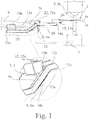
- the proposed holding device for a test sheet 1 has a receiving arrangement 2 for the particular positive engagement with the test sheet 1.
- the test sheet 1 can be any desired, in particular flat, workpiece or a laminated core on which a metalworking step is to be carried out on a trial basis.
- the test sheet 1 is two individual and stacked Aluminum sheets 1a, b, which are to be connected to one another with a rivet joint to be set.
- the receiving assembly 2 is adapted to make an engagement with the test sheet 1, by which engagement the test sheet 1 can be held, lifted and positioned. In addition to this preferably positive engagement, falling out of the test sheet 1 from the receiving arrangement 2 can also be prevented by further measures, which will be described in more detail below.
- the proposed holding device further comprises a handle assembly 3 rigidly connected to the receiving assembly 2 for a user 4 for positioning the test sheet 1.
- a handle assembly 3 rigidly connected to the receiving assembly 2 for a user 4 for positioning the test sheet 1.
- the button assembly 5 generates the switching signal when the button assembly 5 by the user 4, in particular by pressing, is operated.
- the holding device has a transmitting device 6 for transmitting the switching signal.
- the switching signal is transmitted to a control device 7 of a machine tool 8, which control device 7 and machine tool 8 also in the Fig. 1 are shown.
- the transmitting device 6 can be both a device for wireless transmission and, as here, a wired transmission arrangement 6a.
- the machine tool 8 is a riveting machine 8a in the present embodiment.
- the transmitting device 6 can also be set up to receive signals and data from the control device 7.
- the holding device could be adapted to at an attachment point on or at the machine tool 8 z. B. to be mounted pivotally.
- the holding device is portable, namely specifically by gripping the handle assembly 3 by the user 4. This facilitates the use and increases the flexibility of the holding device.
- the handle assembly 3 is adapted for ambidextrous gripping by the user 4. On the one hand, this facilitates the carrying and aligning of the holding device and further ensures that the user 4 actually uses both hands for gripping the handle arrangement 3.
- the handle assembly 3 has two particular spaced individual handles 9a, b for each hand 9c of the user 4. These individual handles 9a, b are specially set up for grasping by a respective hand 9c. Thus, a certain position of the hands is predetermined by the handle assembly 3.
- the push-button arrangement 5 is preferably arranged such that an actuation by the user 4 requires a particularly ambidextrous gripping of the handle arrangement 3 by the user 4.
- this ambidextrous gripping requires embracing the two individual handles 9a, b by the respective one hand 9c of the user 4.
- the functionality for gripping the holding device and that for generating the switching signal are combined in that the probe assembly 5 forms a preferably detachable component of the handle assembly 3.
- the probe assembly 5 forms a preferably detachable component of the handle assembly 3.
- z. B. comprising the approval and release switch already mentioned above, used and in the structure then purely mechanical handle assembly 3 are used.
- the probe assembly 5 has a Schofingertaster 10a and a Maufingertaster 10b, which are actuated by different fingers of the same hand of the user 4. It can - as in the embodiment shown - the Maufingertaster 10b for actuation by a thumb of this hand and a Heilfingertaster 10a for actuation by in particular the middle and ring fingers, possibly also be provided by the index finger, the same hand. Alternatively, a Schofingertaster 10a may be provided for actuation by the index finger and turn a Veryfingertaster 10b for actuation by means and ring finger.
- both the main finger button 10a and the sub finger button 10b would be placed on the same side of the respective single handle 9a, b instead of - as in the present case - on opposite sides of the respective single handle 9a, b.
- the assignment of a button as Hauptfingertaster 10a or as Maufingertaster 10b is arbitrary.
- the probe arrangement 5 has an elongated feeler device 11a, b and the main finger pushbutton 10a and the auxiliary finger pushbutton 10b are arranged offset from one another along a probe longitudinal axis 12a, b of the feeler device 11a, b, which is specifically described in US Pat Fig. 1 is shown.
- the push-button device 11a, b forms part of a single handle 9a, b or is arranged in a single handle 9a, b.
- a “push-button device” can here and below be understood as meaning both a separate device with push-buttons with its own push-button housing and a device with push-buttons, which is formed integrally or monolithically with the respective individual handle 9a, b and thus shares a housing with it ,
- the push-button device can also be detachably arranged in the single handle 9a, b.
- the probe arrangement 5 In order to further reduce the risk of unintentional triggering of the switching signal, it is preferably provided that the probe arrangement 5 generates the switching signal only when the main finger button 10a and the sub finger button 10b are actuated in particular simultaneously.
- the simultaneous operation of the Hauptfingertasters 10a and the Maufingertasters 10b, a grasping of the respective probe device 11a, b presuppose.
- the probe arrangement 5 has two probe devices 11a, b.
- the push-button devices 11a, b are arranged here in particular on a respective individual handle 9a, b and in particular within the respective individual handle 9a, b.
- both Taster devices 11a, b each have a Hauptfingertaster 10a and a Maufingertaster 10b.
- the trigger safety is further increased if it is provided that the probe assembly 5 generates the switching signal only if a particular simultaneous operation of both probe devices 11a, b takes place and preferably only when the Hauptfingertaster 10a both Tasteroara 11a, b and the Maufingertaster 10b at least one push-button device 11a, b - accordingly, a total of at least three buttons - are operated.
- it is arbitrary, whether it is the Crowfingertaster 10b of one or the other Taster réelles 11a, b.
- each push-button device 11a, b can also each push-button device 11a, b more than two fingers, so not only a Hauptfingertaster 10a and a Maufingertaster 10b, then also the operation of more than two finger buttons and especially of all finger buttons both push buttons 11a, b to trigger the switching signal may be required.
- a peculiarity of safety switches which include the above-mentioned release and consent switches, is that the individual push-buttons have an actuation path with a plurality of actuation ranges.
- a risky processing step can only be initiated if the corresponding button is held or actuated in a medium operating range. In this way, it is ensured that both a complete release of the button and a stronger operation - because both reactions reflexively in a moment of shock conceivable - breaks off the risky processing step and z. B. leads to an emergency stop.
- the actuation of the push-button arrangement 5 takes place along an actuation path with at least two actuation areas.
- This variant can advantageously be specified by the fact that the actuation areas have an active area and an inactive area and that the switching signal is generated only when actuated in the active area. Specifically - in the presence of multiple buttons - the switching signal is generated only in a particular simultaneous operation of more than one button in the active area. If a plurality of push-button devices 11a, b are present, it may accordingly be preferred that the switching signal is generated in the active region only when the main finger buttons 10a of both push-button devices 11a, b and the auxiliary finger button 10b of at least one push-button device 11a, b are actuated.
- the holding device has a frame 13 with two substantially parallel arranged and substantially elongated carriers 13a, b. It is preferred that - as shown in the embodiment - the receiving assembly 2 is arranged at each adjacent longitudinal end 14a, b of the two carriers 13a, b. Under the respectively adjacent longitudinal end 14a, b of both carriers in the present sense is to be understood a pair of a first longitudinal end 14a of a first carrier 13a and a second longitudinal end 14b of a second carrier 13b, which - based on the parallel orientation of the carrier 13a, b - pointing in the same direction.
- the receiving arrangement 2 may have a fixing arrangement 15 for fastening the test sheet 1, wherein the fixing arrangement 15 in the present case is a clamping punch arrangement 15a.
- the handle arrangement 3 is arranged on a respective grip region 17a, b of the carriers 13a, b. Due to the substantially elongated design, the carriers 13a, b have a longitudinal axis 16. This respective gripping region 17a, b can then also - as shown in the drawing - each be arranged substantially centrally with respect to this longitudinal axis 16. Likewise, it is preferred that the respective grip area 17a, b at an angle to a longitudinal axis 16 of the carrier 13 a, b is arranged.
- the resulting "gooseneck shape" of the carrier 13a, b which also emerges from the drawing, does not limit the substantially elongated design of the carrier 13a, b or a contradiction to the presence of a longitudinal axis 16. It is also preferable that the individual handles 9a , B are arranged in each case on a carrier 13a, b.
- a support distance 20 from the forearm supports 19a, b to the grip region 17a, b along the longitudinal axis 16 essentially corresponds to a receiving distance 21 from the receiving arrangement 2 to the grip region 17a, b along the longitudinal axis 16.
- Such underarm supports 19a, b facilitate carrying of heavier test sheets 1 with the holding device.
- the holding arrangement has a display device 22 with illuminated displays 22a for indicating an actuation state of the push-button arrangement 5.
- This display device 22 can also reproduce signals from the control device 7 of the machine tool 8.
- the holding arrangement comprises a cover assembly 23, which covers the handle assembly and in particular the individual handles 9a, b in the direction of the receiving device 2.
- the cover assembly 23 at least partially form a cover plane in which the longitudinal axis 16 is located.
- a proposed machine tool 8 for metalworking, and here in particular for producing riveted joints has an end effector 24, which is set up here especially for setting rivets.
- the proposed machine tool 8 also has a control device 7 for driving the end effector 24 and a proposed holding device.
- the proposed machine tool is characterized in that the control device 7 is adapted to trigger the end effector 24 to trigger the switching signal. Consequently, in the present embodiment, the production of a riveted joint on the test sheet 1 is triggered. Further preferred embodiments of the proposed machine tool result arising from the corresponding features and configurations of the proposed holding device.
Landscapes
- Engineering & Computer Science (AREA)
- Mechanical Engineering (AREA)
- General Engineering & Computer Science (AREA)
- Numerical Control (AREA)
- Mechanical Control Devices (AREA)
- Switch Cases, Indication, And Locking (AREA)
- Input From Keyboards Or The Like (AREA)
- Push-Button Switches (AREA)
- Investigating Strength Of Materials By Application Of Mechanical Stress (AREA)
- Lock And Its Accessories (AREA)
- Portable Nailing Machines And Staplers (AREA)
Claims (15)
- Dispositif d'arrêt pour une tôle d'essai (1), comprenant un arrangement d'accueil (2) destiné à venir en prise avec la tôle d'essai (1), un arrangement de poignée (3) relié de manière rigide avec l'arrangement d'accueil (2) pour un utilisateur (4) servant à positionner la tôle d'essai (1), caractérisé par un arrangement de touches (5) destinées à générer un signal de commutation en se basant sur un actionnement par l'utilisateur (4).
- Dispositif d'arrêt selon la revendication 1, caractérisé en ce que le dispositif d'arrêt comprend un dispositif d'émission (6) destiné à la transmission du signal de commutation, de préférence à un système de commande (7) d'une machine-outil (8).
- Dispositif d'arrêt selon la revendication 1 ou 2, caractérisé en ce que le dispositif d'arrêt peut être transporté par l'utilisateur (4), notamment en saisissant l'arrangement de poignée (3).
- Dispositif d'arrêt selon l'une des revendications 1 à 3, caractérisé en ce que l'arrangement de poignée (3) est conçu pour la saisie à deux mains par l'utilisateur (4), l'arrangement de poignée (3) possédant de préférence deux poignées individuelles (9a, b), notamment espacées, encore notamment destinées à être enserrées, respectivement pour une main (9c) de l'utilisateur (4).
- Dispositif d'arrêt selon l'une des revendications 1 à 4, caractérisé en ce que l'arrangement de touches (5) est disposé de telle sorte qu'un actionnement par l'utilisateur (4) suppose une saisie à deux mains de l'arrangement de poignée (3) par l'utilisateur (4), de préférence un enserrage des deux poignées individuelles (9a, b) par la main (9c) respective de l'utilisateur (4).
- Dispositif d'arrêt selon la revendication 5, caractérisé en ce que l'arrangement de touches (5) forme un élément constitutif, de préférence amovible, de l'arrangement de poignée (3).
- Dispositif d'arrêt selon l'une des revendications 1 à 6, caractérisé en ce que l'arrangement de touches (5) possède une touche à doigt principal (10a) et une touche à doigt secondaire (10b), lesquelles peuvent respectivement être actionnées par des doigts différents de la même main de l'utilisateur (4), l'arrangement de touches (5) possédant un appareil à touches (11a, b) allongé et la touche à doigt principal (10a) et la touche à doigt secondaire (10b) étant disposées décalées l'une par rapport à l'autre le long d'un axe longitudinal de touche (12a, b) de l'appareil à touches (11a, b), notamment en ce que l'appareil à touches (11a, b) forme un élément constitutif d'une poignée individuelle (9a, b) ou est disposé dans une poignée individuelle (9a, b).
- Dispositif d'arrêt selon la revendication 7, caractérisé en ce que l'arrangement de touches (5) ne génère le signal de commutation que lorsque la touche à doigt principal (10a) et la touche à doigt secondaire (10b) sont notamment actionnées simultanément, de préférence en ce que l'actionnement simultané de la touche à doigt principal (10a) et de la touche à doigt secondaire (10b) présuppose un enserrage de l'appareil à touches (11a, b) respectif.
- Dispositif d'arrêt selon l'une des revendications 1 à 8, caractérisé en ce que l'arrangement de touches (5) possède deux appareils à touches (11a, b), de préférence les appareils à touches (12a, b) étant disposés respectivement au niveau d'une poignée individuelle (9a, b), notamment à l'intérieur d'une poignée individuelle (9a, b) respective.
- Dispositif d'arrêt selon la revendication 9, caractérisé en ce que les deux appareils à touches (11a, b) possèdent une touche à doigt principal (10a) et une touche à doigt secondaire (10b).
- Dispositif d'arrêt selon la revendication 9 ou 10, caractérisé en ce que l'arrangement de touches (5) ne génère le signal de commutation que lorsqu'un actionnement notamment simultané a lieu au niveau des deux appareils à touches (11a, b), ne génère de préférence le signal de commutation que lorsque la touche à doigt principal (10a) des deux appareils à touches (11a, b) et la touche à doigt secondaire (10b) d'au moins un appareil à touches (11a, b) sont actionnées.
- Dispositif d'arrêt selon l'une des revendications 1 à 11, caractérisé en ce que l'actionnement de l'arrangement de touches (5) s'effectue le long d'une course d'actionnement comprenant au moins deux zones d'actionnement, la touche à doigt principal (10a) et/ou la touche à doigt secondaire (10b), notamment des deux appareils à touches (11a, b), possédant respectivement au moins deux zones d'actionnement.
- Dispositif d'arrêt selon la revendication 12, caractérisé en ce que les zones d'actionnement possèdent une zone active et une zone inactive et en ce que le signal de commutation n'est généré que lors d'un actionnement dans la zone active, de préférence en ce que le signal de commutation n'est généré que lors d'un actionnement notamment simultané des touches à doigt principal (10a) des deux appareils à touches (11a, b) et de la touche à doigt secondaire (10b) d'au moins un appareil à touches (11a, b) dans la zone active.
- Dispositif d'arrêt selon l'une des revendications 1 à 13, caractérisé en ce que le dispositif d'arrêt possède un cadre (13) comprenant au moins deux éléments porteurs (13a, b) disposés sensiblement en parallèle et de configuration sensiblement allongée, de préférence l'arrangement d'accueil (2) étant disposé respectivement au niveau d'une extrémité longitudinale (14a, b) voisine des deux éléments porteurs (13a, b), notamment l'arrangement de poignée (3) étant disposé au niveau d'une zone de poignée (17a, b) respective des éléments porteurs (13a, b), notamment de manière angulaire par rapport à un axe longitudinal (16) des éléments porteurs (13a, b), encore de préférence en ce que les poignées individuelles (9a, b) sont disposées respectivement au niveau d'un élément porteur (13a, b).
- Machine-outil (8) destinée à l'usinage du métal, notamment destinée à fabriquer des assemblages rivetés, comprenant un effecteur terminal (24), notamment destiné à poser des rivets, un système de commande (7) destiné à piloter l'effecteur terminal (24) et un dispositif d'arrêt selon l'une des revendications 1 à 14, caractérisée en ce que le système de commande (7) est conçu pour piloter l'effecteur terminal (24) par déclenchement sur le signal de commutation.
Applications Claiming Priority (2)
| Application Number | Priority Date | Filing Date | Title |
|---|---|---|---|
| DE202014104915.0U DE202014104915U1 (de) | 2014-10-15 | 2014-10-15 | Haltevorrichtung für ein Testblech |
| PCT/EP2015/073888 WO2016059159A1 (fr) | 2014-10-15 | 2015-10-15 | Dispositif de retenue pour une tôle-témoin |
Publications (2)
| Publication Number | Publication Date |
|---|---|
| EP3207302A1 EP3207302A1 (fr) | 2017-08-23 |
| EP3207302B1 true EP3207302B1 (fr) | 2019-01-09 |
Family
ID=54329529
Family Applications (1)
| Application Number | Title | Priority Date | Filing Date |
|---|---|---|---|
| EP15781345.2A Active EP3207302B1 (fr) | 2014-10-15 | 2015-10-15 | Dispositif de retenue pour une tôle-témoin |
Country Status (8)
| Country | Link |
|---|---|
| US (1) | US10807149B2 (fr) |
| EP (1) | EP3207302B1 (fr) |
| CN (1) | CN107000033B (fr) |
| DE (1) | DE202014104915U1 (fr) |
| ES (1) | ES2718556T3 (fr) |
| RU (1) | RU2674794C2 (fr) |
| TR (1) | TR201905029T4 (fr) |
| WO (1) | WO2016059159A1 (fr) |
Families Citing this family (1)
| Publication number | Priority date | Publication date | Assignee | Title |
|---|---|---|---|---|
| DE202014104915U1 (de) | 2014-10-15 | 2016-01-18 | Brötje-Automation GmbH | Haltevorrichtung für ein Testblech |
Family Cites Families (16)
| Publication number | Priority date | Publication date | Assignee | Title |
|---|---|---|---|---|
| US1929484A (en) * | 1926-06-12 | 1933-10-10 | Prosperity Co Inc | Control for power mechanism |
| US1994414A (en) * | 1931-02-18 | 1935-03-12 | Prosperity Co Inc | Garment or ironing press |
| US3628357A (en) * | 1969-11-14 | 1971-12-21 | Verson Allsteel Press Co | Safety control circuit for presses and the like |
| SU651877A1 (ru) * | 1977-09-13 | 1979-03-15 | Государственный Институт По Проектированию Технологии Монтажа Предприятий Химической Промышленности | Устройство дл подачи листового материала в рабочую зону машины дл обработки металлов давлением |
| DE3918673A1 (de) * | 1989-06-08 | 1990-12-13 | Deere & Co | Sicherheitsschaltereinrichtung zur bedienung von maschinen |
| DE4016169A1 (de) * | 1990-05-19 | 1991-11-21 | Darko Dipl Ing Drazic | Beruehrungslose schutz- und steuereinrichtung fuer maschinen |
| US5331831A (en) * | 1993-03-19 | 1994-07-26 | Bermo, Inc. | Hardware sensor |
| JP3177456B2 (ja) * | 1996-10-04 | 2001-06-18 | 富士重工業株式会社 | 塗装樹脂製品の塗膜剥離装置 |
| RU2106220C1 (ru) * | 1996-11-28 | 1998-03-10 | Акционерное общество "АвтоВАЗ" | Клещевой захват |
| BE1016590A3 (nl) | 2005-05-19 | 2007-02-06 | Robosoft Nv | Verbeterde plaatbewerkingsmachine en werkwijze voor het bewerken van platen. |
| ITTO20050705A1 (it) | 2005-10-07 | 2007-04-08 | Crea Srl | Pressa piegatrice per pezzi di lamiera con manipolatore integrato in un dispositivo di posizionamento posteriore |
| CN102554267A (zh) * | 2010-12-31 | 2012-07-11 | 宋树建 | 小型手电车具 |
| CN201997664U (zh) * | 2011-04-21 | 2011-10-05 | 东莞市德生通用电器制造有限公司 | 铆钉装配机 |
| CN203390349U (zh) * | 2013-08-19 | 2014-01-15 | 辛正远 | 一种自动给锡精密焊接设备 |
| CN203509275U (zh) * | 2013-08-22 | 2014-04-02 | 潍坊歌尔电子有限公司 | 除焊吸锡夹子 |
| DE202014104915U1 (de) | 2014-10-15 | 2016-01-18 | Brötje-Automation GmbH | Haltevorrichtung für ein Testblech |
-
2014
- 2014-10-15 DE DE202014104915.0U patent/DE202014104915U1/de not_active Expired - Lifetime
-
2015
- 2015-10-15 CN CN201580055994.XA patent/CN107000033B/zh active Active
- 2015-10-15 ES ES15781345T patent/ES2718556T3/es active Active
- 2015-10-15 US US15/519,202 patent/US10807149B2/en active Active
- 2015-10-15 TR TR2019/05029T patent/TR201905029T4/tr unknown
- 2015-10-15 EP EP15781345.2A patent/EP3207302B1/fr active Active
- 2015-10-15 RU RU2017116577A patent/RU2674794C2/ru active
- 2015-10-15 WO PCT/EP2015/073888 patent/WO2016059159A1/fr not_active Ceased
Non-Patent Citations (1)
| Title |
|---|
| None * |
Also Published As
| Publication number | Publication date |
|---|---|
| TR201905029T4 (tr) | 2019-05-21 |
| RU2017116577A (ru) | 2018-11-15 |
| US20170239710A1 (en) | 2017-08-24 |
| US10807149B2 (en) | 2020-10-20 |
| WO2016059159A1 (fr) | 2016-04-21 |
| ES2718556T3 (es) | 2019-07-02 |
| CN107000033A (zh) | 2017-08-01 |
| CN107000033B (zh) | 2018-12-18 |
| RU2674794C2 (ru) | 2018-12-13 |
| EP3207302A1 (fr) | 2017-08-23 |
| DE202014104915U1 (de) | 2016-01-18 |
| RU2017116577A3 (fr) | 2018-11-15 |
Similar Documents
| Publication | Publication Date | Title |
|---|---|---|
| DE102018107069A1 (de) | Robotersystem | |
| EP3600796B1 (fr) | Effecteur terminal à enveloppe protectrice coulissante pour l'usinage de pièces et système robotisé comprenant un effecteur terminal | |
| DE102020117469A1 (de) | Sicherheitsschaltervorrichtung, die an einem tragbaren endgerät zum bedienen einer maschine angebracht wird, und bedienvorrichtung einer maschine, die mit einer sicherheitsschaltervorrichtung versehen ist | |
| WO2016023057A1 (fr) | Outil de cintrage et dispositif de préhension servant à manipuler l'outil de cintrage | |
| DE102017120030B4 (de) | Werkstückhaltevorrichtung, die Werkstücke durch Festklemmen fixiert | |
| DE1779935B1 (de) | Hilfsgeraet zum einsetzen und herausnehmen des mit einer huelse fest verbundenen fluegelmessers in mischzerkleinerern | |
| DE112017006658B4 (de) | Roboter-Anlernvorrichtung | |
| EP3207302B1 (fr) | Dispositif de retenue pour une tôle-témoin | |
| DE2629722A1 (de) | Handbetaetigbare einbauschaltvorrichtung | |
| DE3312233C1 (de) | Stanzmaschine und Ausklinkmaschine | |
| DE1552657B2 (de) | Vorrichtung zur radialen fuehrung des stanzstempels von aushaumaschinen | |
| DE102020103269A1 (de) | Handhabungsroboter | |
| DE202022102273U1 (de) | Vorrichtung zum manuellen Einbringen von Löchern und/oder Nieten in ein Werkstück | |
| EP3338961B1 (fr) | Dispositif de commande d'un robot et robot pour le nettoyage haute pression à l'eau | |
| DE112022005787T5 (de) | Robotersteuereinrichtung und Robotersystem | |
| DE4025178C2 (fr) | ||
| DE19607168A1 (de) | Vorrichtung mit Sicherheitsschaltersystem mit Werkstückpositioniermechanismus | |
| DE663397C (de) | Automatische handschuetzende Werkstueckniederhalter- und Sperrvorrichtung fuer Stanzen und Pressen bei Einlegearbeit | |
| DE4034155C1 (en) | Cutting notches in metal - involves starting tool and second tool to enlarge first cut | |
| DE318840C (de) | Vorrichtung zur Herstellung von aus einem Plaettchen mit angebogenen Befestigungsstiften bestehenden Schuhschonern | |
| DE1461377A1 (de) | Vorrichtung zum gleichzeitigen oder wechselseitigen Lochen und Heften von Papierstuecken od.dgl. | |
| DE160808C (fr) | ||
| DE112023004868T5 (de) | Verfahren zum Betreiben einer ferngesteuerten Baumaschine mit einer Fernsteuerung und einer auf diese Weise betriebenen ferngesteuerten Baumaschine | |
| DE10226525B4 (de) | Produktionsanlage mit einem einen Bedienerstuhl enthaltenden Bedienplatz und entsprechender Bedienerstuhl | |
| DE568602C (de) | Kombinierte Biege- und Stanzmaschine |
Legal Events
| Date | Code | Title | Description |
|---|---|---|---|
| STAA | Information on the status of an ep patent application or granted ep patent |
Free format text: STATUS: THE INTERNATIONAL PUBLICATION HAS BEEN MADE |
|
| PUAI | Public reference made under article 153(3) epc to a published international application that has entered the european phase |
Free format text: ORIGINAL CODE: 0009012 |
|
| STAA | Information on the status of an ep patent application or granted ep patent |
Free format text: STATUS: REQUEST FOR EXAMINATION WAS MADE |
|
| 17P | Request for examination filed |
Effective date: 20170404 |
|
| AK | Designated contracting states |
Kind code of ref document: A1 Designated state(s): AL AT BE BG CH CY CZ DE DK EE ES FI FR GB GR HR HU IE IS IT LI LT LU LV MC MK MT NL NO PL PT RO RS SE SI SK SM TR |
|
| AX | Request for extension of the european patent |
Extension state: BA ME |
|
| DAV | Request for validation of the european patent (deleted) | ||
| DAX | Request for extension of the european patent (deleted) | ||
| GRAP | Despatch of communication of intention to grant a patent |
Free format text: ORIGINAL CODE: EPIDOSNIGR1 |
|
| STAA | Information on the status of an ep patent application or granted ep patent |
Free format text: STATUS: GRANT OF PATENT IS INTENDED |
|
| INTG | Intention to grant announced |
Effective date: 20180704 |
|
| GRAJ | Information related to disapproval of communication of intention to grant by the applicant or resumption of examination proceedings by the epo deleted |
Free format text: ORIGINAL CODE: EPIDOSDIGR1 |
|
| STAA | Information on the status of an ep patent application or granted ep patent |
Free format text: STATUS: REQUEST FOR EXAMINATION WAS MADE |
|
| GRAP | Despatch of communication of intention to grant a patent |
Free format text: ORIGINAL CODE: EPIDOSNIGR1 |
|
| STAA | Information on the status of an ep patent application or granted ep patent |
Free format text: STATUS: GRANT OF PATENT IS INTENDED |
|
| INTC | Intention to grant announced (deleted) | ||
| INTG | Intention to grant announced |
Effective date: 20181022 |
|
| GRAS | Grant fee paid |
Free format text: ORIGINAL CODE: EPIDOSNIGR3 |
|
| GRAA | (expected) grant |
Free format text: ORIGINAL CODE: 0009210 |
|
| STAA | Information on the status of an ep patent application or granted ep patent |
Free format text: STATUS: THE PATENT HAS BEEN GRANTED |
|
| AK | Designated contracting states |
Kind code of ref document: B1 Designated state(s): AL AT BE BG CH CY CZ DE DK EE ES FI FR GB GR HR HU IE IS IT LI LT LU LV MC MK MT NL NO PL PT RO RS SE SI SK SM TR |
|
| REG | Reference to a national code |
Ref country code: GB Ref legal event code: FG4D Free format text: NOT ENGLISH |
|
| REG | Reference to a national code |
Ref country code: CH Ref legal event code: EP Ref country code: AT Ref legal event code: REF Ref document number: 1087749 Country of ref document: AT Kind code of ref document: T Effective date: 20190115 |
|
| REG | Reference to a national code |
Ref country code: DE Ref legal event code: R096 Ref document number: 502015007637 Country of ref document: DE |
|
| REG | Reference to a national code |
Ref country code: IE Ref legal event code: FG4D Free format text: LANGUAGE OF EP DOCUMENT: GERMAN |
|
| REG | Reference to a national code |
Ref country code: NL Ref legal event code: MP Effective date: 20190109 |
|
| REG | Reference to a national code |
Ref country code: LT Ref legal event code: MG4D |
|
| PG25 | Lapsed in a contracting state [announced via postgrant information from national office to epo] |
Ref country code: NL Free format text: LAPSE BECAUSE OF FAILURE TO SUBMIT A TRANSLATION OF THE DESCRIPTION OR TO PAY THE FEE WITHIN THE PRESCRIBED TIME-LIMIT Effective date: 20190109 |
|
| REG | Reference to a national code |
Ref country code: ES Ref legal event code: FG2A Ref document number: 2718556 Country of ref document: ES Kind code of ref document: T3 Effective date: 20190702 |
|
| PG25 | Lapsed in a contracting state [announced via postgrant information from national office to epo] |
Ref country code: PT Free format text: LAPSE BECAUSE OF FAILURE TO SUBMIT A TRANSLATION OF THE DESCRIPTION OR TO PAY THE FEE WITHIN THE PRESCRIBED TIME-LIMIT Effective date: 20190509 Ref country code: FI Free format text: LAPSE BECAUSE OF FAILURE TO SUBMIT A TRANSLATION OF THE DESCRIPTION OR TO PAY THE FEE WITHIN THE PRESCRIBED TIME-LIMIT Effective date: 20190109 Ref country code: NO Free format text: LAPSE BECAUSE OF FAILURE TO SUBMIT A TRANSLATION OF THE DESCRIPTION OR TO PAY THE FEE WITHIN THE PRESCRIBED TIME-LIMIT Effective date: 20190409 Ref country code: SE Free format text: LAPSE BECAUSE OF FAILURE TO SUBMIT A TRANSLATION OF THE DESCRIPTION OR TO PAY THE FEE WITHIN THE PRESCRIBED TIME-LIMIT Effective date: 20190109 Ref country code: LT Free format text: LAPSE BECAUSE OF FAILURE TO SUBMIT A TRANSLATION OF THE DESCRIPTION OR TO PAY THE FEE WITHIN THE PRESCRIBED TIME-LIMIT Effective date: 20190109 Ref country code: PL Free format text: LAPSE BECAUSE OF FAILURE TO SUBMIT A TRANSLATION OF THE DESCRIPTION OR TO PAY THE FEE WITHIN THE PRESCRIBED TIME-LIMIT Effective date: 20190109 |
|
| PG25 | Lapsed in a contracting state [announced via postgrant information from national office to epo] |
Ref country code: HR Free format text: LAPSE BECAUSE OF FAILURE TO SUBMIT A TRANSLATION OF THE DESCRIPTION OR TO PAY THE FEE WITHIN THE PRESCRIBED TIME-LIMIT Effective date: 20190109 Ref country code: GR Free format text: LAPSE BECAUSE OF FAILURE TO SUBMIT A TRANSLATION OF THE DESCRIPTION OR TO PAY THE FEE WITHIN THE PRESCRIBED TIME-LIMIT Effective date: 20190410 Ref country code: BG Free format text: LAPSE BECAUSE OF FAILURE TO SUBMIT A TRANSLATION OF THE DESCRIPTION OR TO PAY THE FEE WITHIN THE PRESCRIBED TIME-LIMIT Effective date: 20190409 Ref country code: LV Free format text: LAPSE BECAUSE OF FAILURE TO SUBMIT A TRANSLATION OF THE DESCRIPTION OR TO PAY THE FEE WITHIN THE PRESCRIBED TIME-LIMIT Effective date: 20190109 Ref country code: IS Free format text: LAPSE BECAUSE OF FAILURE TO SUBMIT A TRANSLATION OF THE DESCRIPTION OR TO PAY THE FEE WITHIN THE PRESCRIBED TIME-LIMIT Effective date: 20190509 Ref country code: RS Free format text: LAPSE BECAUSE OF FAILURE TO SUBMIT A TRANSLATION OF THE DESCRIPTION OR TO PAY THE FEE WITHIN THE PRESCRIBED TIME-LIMIT Effective date: 20190109 |
|
| REG | Reference to a national code |
Ref country code: DE Ref legal event code: R097 Ref document number: 502015007637 Country of ref document: DE |
|
| PG25 | Lapsed in a contracting state [announced via postgrant information from national office to epo] |
Ref country code: SK Free format text: LAPSE BECAUSE OF FAILURE TO SUBMIT A TRANSLATION OF THE DESCRIPTION OR TO PAY THE FEE WITHIN THE PRESCRIBED TIME-LIMIT Effective date: 20190109 Ref country code: RO Free format text: LAPSE BECAUSE OF FAILURE TO SUBMIT A TRANSLATION OF THE DESCRIPTION OR TO PAY THE FEE WITHIN THE PRESCRIBED TIME-LIMIT Effective date: 20190109 Ref country code: DK Free format text: LAPSE BECAUSE OF FAILURE TO SUBMIT A TRANSLATION OF THE DESCRIPTION OR TO PAY THE FEE WITHIN THE PRESCRIBED TIME-LIMIT Effective date: 20190109 Ref country code: EE Free format text: LAPSE BECAUSE OF FAILURE TO SUBMIT A TRANSLATION OF THE DESCRIPTION OR TO PAY THE FEE WITHIN THE PRESCRIBED TIME-LIMIT Effective date: 20190109 Ref country code: AL Free format text: LAPSE BECAUSE OF FAILURE TO SUBMIT A TRANSLATION OF THE DESCRIPTION OR TO PAY THE FEE WITHIN THE PRESCRIBED TIME-LIMIT Effective date: 20190109 Ref country code: CZ Free format text: LAPSE BECAUSE OF FAILURE TO SUBMIT A TRANSLATION OF THE DESCRIPTION OR TO PAY THE FEE WITHIN THE PRESCRIBED TIME-LIMIT Effective date: 20190109 |
|
| PLBE | No opposition filed within time limit |
Free format text: ORIGINAL CODE: 0009261 |
|
| STAA | Information on the status of an ep patent application or granted ep patent |
Free format text: STATUS: NO OPPOSITION FILED WITHIN TIME LIMIT |
|
| PG25 | Lapsed in a contracting state [announced via postgrant information from national office to epo] |
Ref country code: SM Free format text: LAPSE BECAUSE OF FAILURE TO SUBMIT A TRANSLATION OF THE DESCRIPTION OR TO PAY THE FEE WITHIN THE PRESCRIBED TIME-LIMIT Effective date: 20190109 |
|
| 26N | No opposition filed |
Effective date: 20191010 |
|
| PG25 | Lapsed in a contracting state [announced via postgrant information from national office to epo] |
Ref country code: SI Free format text: LAPSE BECAUSE OF FAILURE TO SUBMIT A TRANSLATION OF THE DESCRIPTION OR TO PAY THE FEE WITHIN THE PRESCRIBED TIME-LIMIT Effective date: 20190109 |
|
| PG25 | Lapsed in a contracting state [announced via postgrant information from national office to epo] |
Ref country code: MC Free format text: LAPSE BECAUSE OF FAILURE TO SUBMIT A TRANSLATION OF THE DESCRIPTION OR TO PAY THE FEE WITHIN THE PRESCRIBED TIME-LIMIT Effective date: 20190109 |
|
| REG | Reference to a national code |
Ref country code: CH Ref legal event code: PL |
|
| PG25 | Lapsed in a contracting state [announced via postgrant information from national office to epo] |
Ref country code: LI Free format text: LAPSE BECAUSE OF NON-PAYMENT OF DUE FEES Effective date: 20191031 Ref country code: CH Free format text: LAPSE BECAUSE OF NON-PAYMENT OF DUE FEES Effective date: 20191031 Ref country code: LU Free format text: LAPSE BECAUSE OF NON-PAYMENT OF DUE FEES Effective date: 20191015 |
|
| REG | Reference to a national code |
Ref country code: BE Ref legal event code: MM Effective date: 20191031 |
|
| PG25 | Lapsed in a contracting state [announced via postgrant information from national office to epo] |
Ref country code: BE Free format text: LAPSE BECAUSE OF NON-PAYMENT OF DUE FEES Effective date: 20191031 |
|
| PG25 | Lapsed in a contracting state [announced via postgrant information from national office to epo] |
Ref country code: IE Free format text: LAPSE BECAUSE OF NON-PAYMENT OF DUE FEES Effective date: 20191015 |
|
| PG25 | Lapsed in a contracting state [announced via postgrant information from national office to epo] |
Ref country code: CY Free format text: LAPSE BECAUSE OF FAILURE TO SUBMIT A TRANSLATION OF THE DESCRIPTION OR TO PAY THE FEE WITHIN THE PRESCRIBED TIME-LIMIT Effective date: 20190109 |
|
| PG25 | Lapsed in a contracting state [announced via postgrant information from national office to epo] |
Ref country code: MT Free format text: LAPSE BECAUSE OF FAILURE TO SUBMIT A TRANSLATION OF THE DESCRIPTION OR TO PAY THE FEE WITHIN THE PRESCRIBED TIME-LIMIT Effective date: 20190109 Ref country code: HU Free format text: LAPSE BECAUSE OF FAILURE TO SUBMIT A TRANSLATION OF THE DESCRIPTION OR TO PAY THE FEE WITHIN THE PRESCRIBED TIME-LIMIT; INVALID AB INITIO Effective date: 20151015 |
|
| REG | Reference to a national code |
Ref country code: AT Ref legal event code: MM01 Ref document number: 1087749 Country of ref document: AT Kind code of ref document: T Effective date: 20201015 |
|
| PG25 | Lapsed in a contracting state [announced via postgrant information from national office to epo] |
Ref country code: AT Free format text: LAPSE BECAUSE OF NON-PAYMENT OF DUE FEES Effective date: 20201015 |
|
| PG25 | Lapsed in a contracting state [announced via postgrant information from national office to epo] |
Ref country code: MK Free format text: LAPSE BECAUSE OF FAILURE TO SUBMIT A TRANSLATION OF THE DESCRIPTION OR TO PAY THE FEE WITHIN THE PRESCRIBED TIME-LIMIT Effective date: 20190109 |
|
| PGFP | Annual fee paid to national office [announced via postgrant information from national office to epo] |
Ref country code: DE Payment date: 20251028 Year of fee payment: 11 |
|
| PGFP | Annual fee paid to national office [announced via postgrant information from national office to epo] |
Ref country code: GB Payment date: 20251024 Year of fee payment: 11 |
|
| PGFP | Annual fee paid to national office [announced via postgrant information from national office to epo] |
Ref country code: IT Payment date: 20251024 Year of fee payment: 11 |
|
| PGFP | Annual fee paid to national office [announced via postgrant information from national office to epo] |
Ref country code: FR Payment date: 20251030 Year of fee payment: 11 |
|
| PGFP | Annual fee paid to national office [announced via postgrant information from national office to epo] |
Ref country code: TR Payment date: 20251007 Year of fee payment: 11 |
|
| PGFP | Annual fee paid to national office [announced via postgrant information from national office to epo] |
Ref country code: ES Payment date: 20251210 Year of fee payment: 11 |