EP3207308B1 - Wallwasher - Google Patents
Wallwasher Download PDFInfo
- Publication number
- EP3207308B1 EP3207308B1 EP15781100.1A EP15781100A EP3207308B1 EP 3207308 B1 EP3207308 B1 EP 3207308B1 EP 15781100 A EP15781100 A EP 15781100A EP 3207308 B1 EP3207308 B1 EP 3207308B1
- Authority
- EP
- European Patent Office
- Prior art keywords
- reflector
- light
- diffuser
- lamp
- leds
- Prior art date
- Legal status (The legal status is an assumption and is not a legal conclusion. Google has not performed a legal analysis and makes no representation as to the accuracy of the status listed.)
- Active
Links
Images

Classifications
-
- F—MECHANICAL ENGINEERING; LIGHTING; HEATING; WEAPONS; BLASTING
- F21—LIGHTING
- F21V—FUNCTIONAL FEATURES OR DETAILS OF LIGHTING DEVICES OR SYSTEMS THEREOF; STRUCTURAL COMBINATIONS OF LIGHTING DEVICES WITH OTHER ARTICLES, NOT OTHERWISE PROVIDED FOR
- F21V7/00—Reflectors for light sources
- F21V7/04—Optical design
-
- F—MECHANICAL ENGINEERING; LIGHTING; HEATING; WEAPONS; BLASTING
- F21—LIGHTING
- F21V—FUNCTIONAL FEATURES OR DETAILS OF LIGHTING DEVICES OR SYSTEMS THEREOF; STRUCTURAL COMBINATIONS OF LIGHTING DEVICES WITH OTHER ARTICLES, NOT OTHERWISE PROVIDED FOR
- F21V3/00—Globes; Bowls; Cover glasses
- F21V3/04—Globes; Bowls; Cover glasses characterised by materials, surface treatments or coatings
-
- F—MECHANICAL ENGINEERING; LIGHTING; HEATING; WEAPONS; BLASTING
- F21—LIGHTING
- F21S—NON-PORTABLE LIGHTING DEVICES; SYSTEMS THEREOF; VEHICLE LIGHTING DEVICES SPECIALLY ADAPTED FOR VEHICLE EXTERIORS
- F21S4/00—Lighting devices or systems using a string or strip of light sources
- F21S4/20—Lighting devices or systems using a string or strip of light sources with light sources held by or within elongate supports
- F21S4/28—Lighting devices or systems using a string or strip of light sources with light sources held by or within elongate supports rigid, e.g. LED bars
-
- F—MECHANICAL ENGINEERING; LIGHTING; HEATING; WEAPONS; BLASTING
- F21—LIGHTING
- F21S—NON-PORTABLE LIGHTING DEVICES; SYSTEMS THEREOF; VEHICLE LIGHTING DEVICES SPECIALLY ADAPTED FOR VEHICLE EXTERIORS
- F21S8/00—Lighting devices intended for fixed installation
- F21S8/04—Lighting devices intended for fixed installation intended only for mounting on a ceiling or the like overhead structures
-
- F—MECHANICAL ENGINEERING; LIGHTING; HEATING; WEAPONS; BLASTING
- F21—LIGHTING
- F21V—FUNCTIONAL FEATURES OR DETAILS OF LIGHTING DEVICES OR SYSTEMS THEREOF; STRUCTURAL COMBINATIONS OF LIGHTING DEVICES WITH OTHER ARTICLES, NOT OTHERWISE PROVIDED FOR
- F21V19/00—Fastening of light sources or lamp holders
- F21V19/001—Fastening of light sources or lamp holders the light sources being semiconductors devices, e.g. LEDs
- F21V19/003—Fastening of light source holders, e.g. of circuit boards or substrates holding light sources
-
- F—MECHANICAL ENGINEERING; LIGHTING; HEATING; WEAPONS; BLASTING
- F21—LIGHTING
- F21V—FUNCTIONAL FEATURES OR DETAILS OF LIGHTING DEVICES OR SYSTEMS THEREOF; STRUCTURAL COMBINATIONS OF LIGHTING DEVICES WITH OTHER ARTICLES, NOT OTHERWISE PROVIDED FOR
- F21V3/00—Globes; Bowls; Cover glasses
-
- F—MECHANICAL ENGINEERING; LIGHTING; HEATING; WEAPONS; BLASTING
- F21—LIGHTING
- F21V—FUNCTIONAL FEATURES OR DETAILS OF LIGHTING DEVICES OR SYSTEMS THEREOF; STRUCTURAL COMBINATIONS OF LIGHTING DEVICES WITH OTHER ARTICLES, NOT OTHERWISE PROVIDED FOR
- F21V7/00—Reflectors for light sources
- F21V7/0008—Reflectors for light sources providing for indirect lighting
-
- F—MECHANICAL ENGINEERING; LIGHTING; HEATING; WEAPONS; BLASTING
- F21—LIGHTING
- F21V—FUNCTIONAL FEATURES OR DETAILS OF LIGHTING DEVICES OR SYSTEMS THEREOF; STRUCTURAL COMBINATIONS OF LIGHTING DEVICES WITH OTHER ARTICLES, NOT OTHERWISE PROVIDED FOR
- F21V7/00—Reflectors for light sources
- F21V7/005—Reflectors for light sources with an elongated shape to cooperate with linear light sources
-
- F—MECHANICAL ENGINEERING; LIGHTING; HEATING; WEAPONS; BLASTING
- F21—LIGHTING
- F21V—FUNCTIONAL FEATURES OR DETAILS OF LIGHTING DEVICES OR SYSTEMS THEREOF; STRUCTURAL COMBINATIONS OF LIGHTING DEVICES WITH OTHER ARTICLES, NOT OTHERWISE PROVIDED FOR
- F21V7/00—Reflectors for light sources
- F21V7/04—Optical design
- F21V7/09—Optical design with a combination of different curvatures
-
- F—MECHANICAL ENGINEERING; LIGHTING; HEATING; WEAPONS; BLASTING
- F21—LIGHTING
- F21Y—INDEXING SCHEME ASSOCIATED WITH SUBCLASSES F21K, F21L, F21S and F21V, RELATING TO THE FORM OR THE KIND OF THE LIGHT SOURCES OR OF THE COLOUR OF THE LIGHT EMITTED
- F21Y2103/00—Elongate light sources, e.g. fluorescent tubes
- F21Y2103/10—Elongate light sources, e.g. fluorescent tubes comprising a linear array of point-like light-generating elements
-
- F—MECHANICAL ENGINEERING; LIGHTING; HEATING; WEAPONS; BLASTING
- F21—LIGHTING
- F21Y—INDEXING SCHEME ASSOCIATED WITH SUBCLASSES F21K, F21L, F21S and F21V, RELATING TO THE FORM OR THE KIND OF THE LIGHT SOURCES OR OF THE COLOUR OF THE LIGHT EMITTED
- F21Y2115/00—Light-generating elements of semiconductor light sources
- F21Y2115/10—Light-emitting diodes [LED]
Definitions
- the present invention relates to a luminaire intended for use as a so-called wall washer.
- a wallwasher is understood to be a luminaire which is specially designed to illuminate a vertical surface of a room, that is to say in particular its wall.
- this lights are used, which are arranged on a horizontally oriented base surface, so for example the ceiling of a room, directly on this or suspended from this and are designed in terms of their light output such that they are, for example, an obliquely located below the mounting position of the lamp wall illuminate.
- the light distribution curve of a wall washer is rather asymmetrical.
- US 2008/204888 A1 refers to an optical system for mixing and redirecting light to illuminate a target surface.
- the system includes a first reflector for receiving a light emitted from the light source (called a first light).
- the light reflected by the first reflector (called the second light) falls on a first diffuser and is transmitted as a so-called third light, namely, reflected to a second reflector and projected onto a second diffuser.
- DE 10 2007 001702 A1 refers to a lighting device (for low ceiling systems, for example, in the aircraft) in the form of a combination of areal backlighting and a reflection of reflected light on a side facing the observer to produce optical depth effect.
- the device consists of two curved, parallel spaced surfaces whose first surface Observer side of a first, hidden behind a panel light source is irradiated. A diffuser between the first light source and the first surface scatters the light emitted from the first light source.
- the second light source faces the second surface, wherein the latter may alternatively or additionally be light-scattering.
- US 8038321 B1 refers to a luminaire housing in which light rays are projected onto a (curved) stationary reflector in the form of a concave reflecting surface. The reflected light passes through the light passageway, passing through a light-spreading or distribution lens, possibly further reflected at an aperture reflector, and finally projective, ie, not diffusely exiting the housing.
- the prior art also shows that in the solutions known hitherto the luminaires must have a certain minimum size in order to be able to achieve a satisfactory illumination of the wall area.
- the present invention is therefore based on the object to provide a novel way to realize a Wallwashers, in spite of a relatively small construction of the lamp, a homogeneous, uniform light field can be achieved on a wall area to be illuminated.
- the solution according to the invention provides for a combination of different measures which, on the one hand, lead to a small construction of the lamp or the wall washer, on the other hand, make it possible to achieve a uniform and homogeneous light distribution.
- LEDs are used as the light source, which are arranged one behind the other in a longitudinal direction of the lamp. The light emitted by these LEDs light is not emitted directly through the lamp but with the help of a concave reflector reflected back so that a light output is made laterally downwards.
- the lamps or LEDs are in this case arranged in the upper region of the reflector so that they light in Essentially opposite to the light emission direction of the lamp to emit the reflector.
- the invention proposes a luminaire which has luminous means which have LEDs arranged one after the other in a longitudinal direction of the luminaire.
- a reflector which is concavely curved in a plane perpendicular to a longitudinal axis of the luminaire, wherein the luminous means in the upper region of the reflector are arranged such that they emit light substantially opposite to a light emission direction of the luminaire onto the reflector.
- a diffuser is arranged below the luminous means, which diffuser extends substantially from a plane in which the luminous means are arranged to the reflector, and wherein the diffuser is oriented substantially perpendicular to this plane and the reflector is aligned in the upper region has a greater curvature than at the bottom.
- the invention is characterized in that the diffuser divides the reflector into two regions, wherein the first reflector region is the upper region of the reflector and faces the LEDs, and wherein the second reflector region is the lower region of the reflector and is on the side facing away from the LEDs the diffuser is located.
- the lighting means so the LEDs, apart from that region of the reflector, which they are opposite, completely separated by the diffuser from the reflector.
- the bulbs, the upper end of the reflector and the diffuser thus enclose a small, running in the longitudinal direction of the lamp so-called mixing chamber in which substantially the desired homogeneous distribution of the light is made. Only the light emerging from this mixing chamber via the diffuser, which is then reflected by the reflector in Lichtabstrahlraum the light out, then leave the light. All the light that is emitted by the lamp, so initially through the diffuser influenced, which ultimately the desired uniform light distribution can be obtained.
- the reflector is concavely curved, it being provided that it has a greater curvature in the upper region, ie the region to which the illuminants are assigned, than in the lower region. This ensures that even such light, which is emitted from the LEDs at relatively shallow angles, still efficiently reflected by the reflector within the above-mentioned mixing chamber and can be directed through the diffuser in the actual responsible for the light output of the lamp reflector area.
- At least in front of the lower region of the reflector can preferably be arranged a glass or PMMA existing cover.
- the arrangement of this cover can be in particular such that it extends approximately from the reflector facing away from the end of the diffuser to the lower edge of the reflector.
- the cover may extend substantially in the plane in which the bulbs are arranged.
- a profiled base body which may be formed for example by an aluminum extruded profile. This can be designed both for the direct installation of a ceiling and for attachment to a support element, for example a so-called support rail of a lighting system or the like.
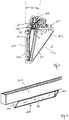
- FIG. 1 shows first an overall view of the generally provided with the reference numeral 100 lamp according to the invention, which should be used as already mentioned as a so-called wall washer.
- the reference numeral 100 lamp As usual in such lights their assembly takes place on a horizontal mounting surface, so for example on the ceiling of a room or in a comparable manner. In the intended operating mode, this would mean that the in FIG. 1 with the reference numeral 110 provided rear wall of the housing 101 is oriented substantially vertically. However, the light of the luminaire 100 is then not emitted horizontally or vertically downwards but rather obliquely laterally downwards, so that in the case where the luminaire is arranged in the vicinity of a wall, the wall area located obliquely below it is illuminated.
- the aim is for the so-called light field generated on the wall to be illuminated to have the most uniform possible homogeneous brightness.
- special measures are responsible for the light output, which will be explained in more detail below with reference to the other figures.
- the light emitted by the luminous means is not directed directly onto the wall to be illuminated, but instead is indirectly emitted during a so-called retro-reflection.
- LEDs 5 are used as the light source, which are arranged one after the other in the longitudinal direction I of the luminaire 100 and are aligned such that they initially emit their light in the opposite direction to the main emission direction A of the luminaire 100.
- the arrangement of the LEDs 5 takes place with the help of one or more boards 6, which are preferably slightly inclined relative to the vertical defined by the rear wall 101 at an angle ⁇ of about 10 ° to 20 °, in particular about 15 °.
- the actual deflection of the light emitted by the LEDs 5 in the direction of the light emission direction A of the luminaire 100 takes place with the aid of a reflector 10 which extends from an underside of the luminaire housing 101 to an area just above the LEDs 5.
- This invariably embodied in the longitudinal direction I of the lamp 100 reflector 10 has a concave shape in a plane perpendicular to the longitudinal direction I, where he could either be executed correspondingly angled, according to the invention, however, continuously concave curved as shown.
- the preferably made of a highly reflective material reflector 10 thus serves as a so-called back reflector to give off the light obliquely laterally towards the bottom.
- the reflector 10 over the height of the lamp 100 away across no constant curvature but is shaped such that the curvature in the upper region 11, ie the area in the vicinity of which the LEDs are 5, is strongest.
- this allows the dimensions of the mixing chamber 25 are kept relatively compact, on the other hand it is ensured that even light, which is emitted from the LEDs 5 at shallow angles, for example, vertically upwards, is still reflected back from the reflector to the diffuser 20 and as for the light output of the lamp 100 usable light can be used.
- the curvature of the reflector 10 in the area located below the diffuser 20 is then selected such that in this way the desired shape or dimension of the light field on the wall to be illuminated can be achieved.
- an additional cover plate 30 is disposed in front of the lower portion of the reflector, which extends from the lower end of the reflector 10 to the diffuser 20 back.
- This cover 30 defines the actual light exit region of the lamp 100, however, has relatively little influence on the light output, since it is preferably made crystal clear and for this purpose consists of either glass or PMMA.
- the actual light-emitting properties of the luminaire 100 are primarily determined by the arrangement and design of the reflector 10 and the diffuser 20.
- the diffuser 20 itself is preferably formed by a diffuser film which ideally has at least some inherent stability so that it retains its shape and arrangement as shown.
- a film which is sold under the name Brightview Film Circular 15 degrees has been found because when using this film particularly advantageous Lichtabrahleigenschaften can be achieved. This also applies to the case that the luminaire has very compact dimensions of, for example, 40x50mm.
- the holder and arrangement of the various components of the lamp 100 according to the invention is carried out, as already mentioned, preferably with the aid of an extruded aluminum profile, whose configuration in turn is the sectional view of Figures 2 and 3 can be removed.
- This profile part is executed approximately angled and has on the one hand a vertically oriented leg 102, which forms the rear wall 110 of the lamp 100, and a horizontal leg 103, in particular the inclusion of electronic components for operating the LEDs 5 and the assembly of the lamp 100 at a suitable carrier.
- an approximately trapezoidal receiving area 104 is provided in the upper region of the profile part, in the one hand from the bottom of the reflector 10 projects with its upper end portion 11 and the recording of the LED boards 6 is used.
- operating means for operating the LEDs 5 are also arranged within this receiving space.
- This may in particular be a converter or the like, wherein the side walls of this receiving area 104 additionally also have openings or feedthroughs 105 for the feeding of cables or the like.
- the aluminum profile body in this case has a plurality of longitudinally extending grooves or channels, which allow easy insertion of the optical components described above. It can be seen, for example, that the cover plate 30 is received with its upper and lower end respectively in longitudinally extending grooves, so that they can be easily inserted from an end face into the profile body.
- a receptacle and mounting of the reflector 10 which is supported on the one hand at its upper and lower end, but in addition also on its rear side by the profile body.
- the reflector automatically when inserting the illustrated curvature assumes.
- the storage of the diffuser 20 in a corresponding recess extending in the longitudinal direction of the profile body, so that - apart from the LED boards 6 - all essential components of the lamp 100 are held without additional support means on the profile body.
- two correspondingly shaped end caps 120 serve two more longitudinally extending channels that allow the placement and reliable holding the end caps 120.
- FIG. 4 A conceivable arrangement of the wall washer 100 according to the invention on a support is in FIG. 4 illustrated, in which case the carrier rail of a lighting system is used as a carrier element 200.
- the support rail is approximately U-shaped and open to the bottom open, so that the lamp 100 can be attached in a simple manner from the bottom to the mounting rail 200 and fastened there, in which case the upper components, in particular the above mentioned receiving area 104 of the profile body with the operating means located thereon are received in the receiving space of the mounting rail 200.
- An attachment to the support rail 200 is achieved here by means of two clamping webs 106, which are formed at the upper portion of the horizontally extending leg 103 of the profile body.
Landscapes
- Engineering & Computer Science (AREA)
- General Engineering & Computer Science (AREA)
- Non-Portable Lighting Devices Or Systems Thereof (AREA)
Claims (5)
- Luminaire (100) comprenant
des sources d'éclairage, lesquelles comprennent des LED (5) disposées les unes derrière les autres dans une direction longitudinale (I) du luminaire (100), ainsi
qu'un réflecteur (10), qui est courbé de manière concave dans un plan perpendiculaire à la direction longitudinale (I) du luminaire (100),
les sources d'éclairage dans la zone supérieure (11) du réflecteur (10) étant disposées de telle façon qu'elles émettent de la lumière sur le réflecteur (10) dans une direction essentiellement opposée à la direction d'émission de lumière (A) du luminaire (100),
un diffuseur (20) étant disposé en dessous des sources d'éclairage, lequel s'étend essentiellement d'un plan, dans lequel sont disposées les sources d'éclairage, jusqu'au réflecteur (10), et le diffuseur (20) étant orienté essentiellement perpendiculairement à ce plan et le réflecteur (10) présentant dans la zone supérieure (11) une courbure plus forte que celle dans la zone inférieure,
caractérisé en ce
que le diffuseur (20) divise le réflecteur (10) en deux zones, la première zone de réflexion étant la zone supérieure (11) du réflecteur (10) et faisant face aux LED (5) et la deuxième zone de réflexion étant la zone inférieure du réflecteur (10) et se trouvant sur le côté du diffuseur (20) qui est opposé aux LED (5). - Luminaire selon l'une quelconque des revendications précédentes, caractérisé en ce qu'il comprend une plaque de recouvrement (30), de préférence en verre ou en PMMA, laquelle est disposée devant la partie inférieure du réflecteur (10).
- Luminaire selon la revendication 2, caractérisé en ce que la plaque de recouvrement (30) s'étend de l'extrémité du diffuseur (20) opposée au réflecteur (10) jusqu'au bord inférieur du réflecteur (10).
- Luminaire selon la revendication 2 ou 3, caractérisé en ce que la plaque de recouvrement (30) s'étend essentiellement dans le plan dans lequel sont disposées les sources d'éclairage.
- Luminaire selon l'une quelconque des revendications précédentes, caractérisé en ce qu'il s'agit d'un lèche-mur.
Applications Claiming Priority (2)
| Application Number | Priority Date | Filing Date | Title |
|---|---|---|---|
| DE202014104900.2U DE202014104900U1 (de) | 2014-10-15 | 2014-10-15 | Leuchte zur Verwendung als Wallwasher |
| PCT/EP2015/073864 WO2016059148A1 (fr) | 2014-10-15 | 2015-10-15 | Lèche-mur |
Publications (2)
| Publication Number | Publication Date |
|---|---|
| EP3207308A1 EP3207308A1 (fr) | 2017-08-23 |
| EP3207308B1 true EP3207308B1 (fr) | 2019-06-26 |
Family
ID=54325551
Family Applications (1)
| Application Number | Title | Priority Date | Filing Date |
|---|---|---|---|
| EP15781100.1A Active EP3207308B1 (fr) | 2014-10-15 | 2015-10-15 | Wallwasher |
Country Status (4)
| Country | Link |
|---|---|
| US (1) | US10222028B2 (fr) |
| EP (1) | EP3207308B1 (fr) |
| DE (1) | DE202014104900U1 (fr) |
| WO (1) | WO2016059148A1 (fr) |
Families Citing this family (6)
| Publication number | Priority date | Publication date | Assignee | Title |
|---|---|---|---|---|
| JP1553416S (fr) * | 2015-06-18 | 2016-07-11 | ||
| CN107781787B (zh) | 2016-08-29 | 2020-12-08 | 查克森科技有限公司 | 照明装置和照明系统 |
| DE202018104615U1 (de) * | 2018-08-10 | 2019-11-14 | Zumtobel Lighting Gmbh | Leuchte mit veränderbarer Lichtabgabe |
| USD925805S1 (en) * | 2018-11-21 | 2021-07-20 | Ansorg Gmbh | Ceiling lamp |
| DE102019106678A1 (de) * | 2019-03-15 | 2020-09-17 | Siteco Gmbh | Modulare Wall- und Shelfwasher |
| US11175012B1 (en) * | 2020-07-08 | 2021-11-16 | Abl Ip Holding Llc | Indirect light wall pack |
Family Cites Families (21)
| Publication number | Priority date | Publication date | Assignee | Title |
|---|---|---|---|---|
| US5115384A (en) * | 1990-11-15 | 1992-05-19 | Arriflex Corporation | Soft light |
| US5199782A (en) * | 1991-05-23 | 1993-04-06 | Glen Co. Breda & Associates, Inc. | Illumination system for vanity or the like |
| US5709460A (en) * | 1996-12-17 | 1998-01-20 | Covelight Corporation | Indirect fluorescent lighting fixture |
| DE29906806U1 (de) * | 1999-04-19 | 2000-08-31 | ERCO Leuchten GmbH, 58507 Lüdenscheid | Reflektorleuchte, die als Flächenfluter, wie z.B. als Wand- oder Deckenfluter, ausgebildet ist |
| US6663262B2 (en) * | 2001-09-10 | 2003-12-16 | 3M Innovative Properties Company | Backlighting transmissive displays |
| US6789914B1 (en) * | 2003-05-29 | 2004-09-14 | Hubbell Incorporated | Luminaire providing direct and indirect lighting |
| DE102004051661B3 (de) * | 2004-10-22 | 2006-03-30 | Erco Leuchten Gmbh | Leuchte und Lichtquelleneinheit zur Ausleuchtung einer Gebäudefläche oder einer Gebäudeteilfläche |
| US7740387B2 (en) * | 2006-05-24 | 2010-06-22 | 3M Innovative Properties Company | Backlight wedge with side mounted light source |
| DE102007001702B4 (de) | 2007-01-11 | 2010-04-08 | Airbus Deutschland Gmbh | Beleuchtungsvorrichtung eines Luftfahrzeugs |
| WO2008098360A1 (fr) * | 2007-02-16 | 2008-08-21 | Koninklijke Philips Electronics N.V. | Système optique pour luminaire |
| EP2150851B1 (fr) * | 2007-05-29 | 2015-03-11 | Koninklijke Philips N.V. | Système d'éclairage, luminaire et unité de rétroéclairage |
| DE102007059607A1 (de) | 2007-12-11 | 2009-06-18 | Bartenbach, Christian, Ing. | Wand- und/oder Deckenleuchte |
| US8038327B1 (en) * | 2008-05-06 | 2011-10-18 | Genlyte Thomas Group Llc | Color mixing luminaire |
| US8038321B1 (en) * | 2008-05-06 | 2011-10-18 | Koninklijke Philips Electronics N.V. | Color mixing luminaire |
| ES2592168T3 (es) * | 2008-09-12 | 2016-11-28 | Philips Lighting Holding B.V. | Luminaria y sistema de iluminación |
| US8113680B2 (en) * | 2009-05-05 | 2012-02-14 | Lightology, Llc | Light fixture with directed LED light |
| CN101994940B (zh) * | 2009-08-19 | 2015-04-01 | Lg伊诺特有限公司 | 照明装置 |
| EP2636945B1 (fr) * | 2010-09-16 | 2015-09-02 | LG Innotek Co., Ltd. | Dispositif d'éclairage |
| JP6061479B2 (ja) * | 2012-03-12 | 2017-01-18 | ミネベア株式会社 | 照明装置 |
| ITFI20130065A1 (it) * | 2013-03-26 | 2014-09-27 | Iguzzini Illuminazione | Apparecchio di illuminazione di tipo wall washer. |
| US9726337B2 (en) * | 2014-08-27 | 2017-08-08 | R. W. Swarens Associates, Inc. | Light fixture for indirect asymmetric illumination with LEDs |
-
2014
- 2014-10-15 DE DE202014104900.2U patent/DE202014104900U1/de not_active Expired - Lifetime
-
2015
- 2015-10-15 WO PCT/EP2015/073864 patent/WO2016059148A1/fr not_active Ceased
- 2015-10-15 EP EP15781100.1A patent/EP3207308B1/fr active Active
- 2015-10-15 US US15/503,166 patent/US10222028B2/en active Active
Non-Patent Citations (1)
| Title |
|---|
| None * |
Also Published As
| Publication number | Publication date |
|---|---|
| WO2016059148A1 (fr) | 2016-04-21 |
| US10222028B2 (en) | 2019-03-05 |
| US20170234508A1 (en) | 2017-08-17 |
| DE202014104900U1 (de) | 2016-01-18 |
| EP3207308A1 (fr) | 2017-08-23 |
Similar Documents
| Publication | Publication Date | Title |
|---|---|---|
| EP1378771B1 (fr) | Eclairage intérieur | |
| EP1979668B1 (fr) | Lampe comprenant un logement sous forme de boitier et element de sortie d'eclairage | |
| EP1043542B2 (fr) | Système d' éclairage pour installation au plafond ou au mur d' une pièce | |
| DE102008060874A1 (de) | Leuchte | |
| WO2016059148A1 (fr) | Lèche-mur | |
| DE102007059607A1 (de) | Wand- und/oder Deckenleuchte | |
| EP2993394B1 (fr) | Dispositif d'éclairage | |
| DE10011378B4 (de) | Hohllichtleiterleuchte mit indirekter Lichtabstrahlung | |
| EP2258978B1 (fr) | Luminaire avec une glace de fermeture transparente | |
| DE102014207640A1 (de) | Anordnung zur Lichtabgabe zur Anordnung an einem Leuchtengehäuse | |
| EP4509755A1 (fr) | Dispositif d'éclairage | |
| EP2796779B1 (fr) | Éclairage doté de système optique d'émission de lumière à travers une ouverture de sortie de lumière longitudinale | |
| EP1496308A2 (fr) | Lampe d'éclairage intérieur avec un élément réfractif | |
| EP4168711B1 (fr) | Ensemble d'émission de lumière, et luminaire | |
| EP3112747B1 (fr) | Élement optique destine a influencer l'emission lumineuse d'une source lumineuse allongee | |
| EP4107426B1 (fr) | Lampe allongée | |
| DE10354462B4 (de) | Leuchte mit asymmetrischer Lichtabstrahlung | |
| WO2002044614A1 (fr) | Lampe dotee d'une plaque de recouvrement | |
| DE202012100628U1 (de) | Leuchte mit einem länglichen Gehäuse und Anbauelement hierfür | |
| EP1843082B1 (fr) | Plafonnier, en particulier pour utilisation dans un couloir | |
| DE202017105773U1 (de) | Deckenleuchte sowie Beleuchtungsvorrichtung umfassend eine Anzahl von Deckenleuchten | |
| AT18305U1 (de) | Deckenleuchte und Beleuchtungsanordnung | |
| EP3798506A1 (fr) | Couvercle de luminaire pour un système d'éclairage linéaire | |
| AT16410U1 (de) | Anordnung zur flächigen Lichtabgabe |
Legal Events
| Date | Code | Title | Description |
|---|---|---|---|
| STAA | Information on the status of an ep patent application or granted ep patent |
Free format text: STATUS: THE INTERNATIONAL PUBLICATION HAS BEEN MADE |
|
| PUAI | Public reference made under article 153(3) epc to a published international application that has entered the european phase |
Free format text: ORIGINAL CODE: 0009012 |
|
| STAA | Information on the status of an ep patent application or granted ep patent |
Free format text: STATUS: REQUEST FOR EXAMINATION WAS MADE |
|
| 17P | Request for examination filed |
Effective date: 20170412 |
|
| AK | Designated contracting states |
Kind code of ref document: A1 Designated state(s): AL AT BE BG CH CY CZ DE DK EE ES FI FR GB GR HR HU IE IS IT LI LT LU LV MC MK MT NL NO PL PT RO RS SE SI SK SM TR |
|
| AX | Request for extension of the european patent |
Extension state: BA ME |
|
| DAV | Request for validation of the european patent (deleted) | ||
| DAX | Request for extension of the european patent (deleted) | ||
| STAA | Information on the status of an ep patent application or granted ep patent |
Free format text: STATUS: EXAMINATION IS IN PROGRESS |
|
| 17Q | First examination report despatched |
Effective date: 20181031 |
|
| REG | Reference to a national code |
Ref country code: DE Ref legal event code: R079 Ref document number: 502015009460 Country of ref document: DE Free format text: PREVIOUS MAIN CLASS: F21V0007000000 Ipc: F21V0007090000 |
|
| GRAP | Despatch of communication of intention to grant a patent |
Free format text: ORIGINAL CODE: EPIDOSNIGR1 |
|
| STAA | Information on the status of an ep patent application or granted ep patent |
Free format text: STATUS: GRANT OF PATENT IS INTENDED |
|
| RIC1 | Information provided on ipc code assigned before grant |
Ipc: F21V 3/04 20180101ALI20190313BHEP Ipc: F21V 7/00 20060101ALN20190313BHEP Ipc: F21Y 103/10 20160101ALN20190313BHEP Ipc: F21V 7/09 20060101AFI20190313BHEP Ipc: F21Y 115/10 20160101ALN20190313BHEP Ipc: F21S 8/04 20060101ALI20190313BHEP |
|
| INTG | Intention to grant announced |
Effective date: 20190410 |
|
| GRAS | Grant fee paid |
Free format text: ORIGINAL CODE: EPIDOSNIGR3 |
|
| GRAA | (expected) grant |
Free format text: ORIGINAL CODE: 0009210 |
|
| STAA | Information on the status of an ep patent application or granted ep patent |
Free format text: STATUS: THE PATENT HAS BEEN GRANTED |
|
| AK | Designated contracting states |
Kind code of ref document: B1 Designated state(s): AL AT BE BG CH CY CZ DE DK EE ES FI FR GB GR HR HU IE IS IT LI LT LU LV MC MK MT NL NO PL PT RO RS SE SI SK SM TR |
|
| REG | Reference to a national code |
Ref country code: GB Ref legal event code: FG4D Free format text: NOT ENGLISH |
|
| REG | Reference to a national code |
Ref country code: CH Ref legal event code: EP |
|
| REG | Reference to a national code |
Ref country code: AT Ref legal event code: REF Ref document number: 1148714 Country of ref document: AT Kind code of ref document: T Effective date: 20190715 |
|
| REG | Reference to a national code |
Ref country code: DE Ref legal event code: R096 Ref document number: 502015009460 Country of ref document: DE |
|
| REG | Reference to a national code |
Ref country code: IE Ref legal event code: FG4D Free format text: LANGUAGE OF EP DOCUMENT: GERMAN |
|
| REG | Reference to a national code |
Ref country code: NL Ref legal event code: MP Effective date: 20190626 |
|
| PG25 | Lapsed in a contracting state [announced via postgrant information from national office to epo] |
Ref country code: LT Free format text: LAPSE BECAUSE OF FAILURE TO SUBMIT A TRANSLATION OF THE DESCRIPTION OR TO PAY THE FEE WITHIN THE PRESCRIBED TIME-LIMIT Effective date: 20190626 Ref country code: FI Free format text: LAPSE BECAUSE OF FAILURE TO SUBMIT A TRANSLATION OF THE DESCRIPTION OR TO PAY THE FEE WITHIN THE PRESCRIBED TIME-LIMIT Effective date: 20190626 Ref country code: NO Free format text: LAPSE BECAUSE OF FAILURE TO SUBMIT A TRANSLATION OF THE DESCRIPTION OR TO PAY THE FEE WITHIN THE PRESCRIBED TIME-LIMIT Effective date: 20190926 Ref country code: HR Free format text: LAPSE BECAUSE OF FAILURE TO SUBMIT A TRANSLATION OF THE DESCRIPTION OR TO PAY THE FEE WITHIN THE PRESCRIBED TIME-LIMIT Effective date: 20190626 Ref country code: AL Free format text: LAPSE BECAUSE OF FAILURE TO SUBMIT A TRANSLATION OF THE DESCRIPTION OR TO PAY THE FEE WITHIN THE PRESCRIBED TIME-LIMIT Effective date: 20190626 Ref country code: SE Free format text: LAPSE BECAUSE OF FAILURE TO SUBMIT A TRANSLATION OF THE DESCRIPTION OR TO PAY THE FEE WITHIN THE PRESCRIBED TIME-LIMIT Effective date: 20190626 |
|
| REG | Reference to a national code |
Ref country code: LT Ref legal event code: MG4D |
|
| PG25 | Lapsed in a contracting state [announced via postgrant information from national office to epo] |
Ref country code: RS Free format text: LAPSE BECAUSE OF FAILURE TO SUBMIT A TRANSLATION OF THE DESCRIPTION OR TO PAY THE FEE WITHIN THE PRESCRIBED TIME-LIMIT Effective date: 20190626 Ref country code: LV Free format text: LAPSE BECAUSE OF FAILURE TO SUBMIT A TRANSLATION OF THE DESCRIPTION OR TO PAY THE FEE WITHIN THE PRESCRIBED TIME-LIMIT Effective date: 20190626 Ref country code: GR Free format text: LAPSE BECAUSE OF FAILURE TO SUBMIT A TRANSLATION OF THE DESCRIPTION OR TO PAY THE FEE WITHIN THE PRESCRIBED TIME-LIMIT Effective date: 20190927 Ref country code: BG Free format text: LAPSE BECAUSE OF FAILURE TO SUBMIT A TRANSLATION OF THE DESCRIPTION OR TO PAY THE FEE WITHIN THE PRESCRIBED TIME-LIMIT Effective date: 20190926 |
|
| PG25 | Lapsed in a contracting state [announced via postgrant information from national office to epo] |
Ref country code: NL Free format text: LAPSE BECAUSE OF FAILURE TO SUBMIT A TRANSLATION OF THE DESCRIPTION OR TO PAY THE FEE WITHIN THE PRESCRIBED TIME-LIMIT Effective date: 20190626 Ref country code: CZ Free format text: LAPSE BECAUSE OF FAILURE TO SUBMIT A TRANSLATION OF THE DESCRIPTION OR TO PAY THE FEE WITHIN THE PRESCRIBED TIME-LIMIT Effective date: 20190626 Ref country code: PT Free format text: LAPSE BECAUSE OF FAILURE TO SUBMIT A TRANSLATION OF THE DESCRIPTION OR TO PAY THE FEE WITHIN THE PRESCRIBED TIME-LIMIT Effective date: 20191028 Ref country code: SK Free format text: LAPSE BECAUSE OF FAILURE TO SUBMIT A TRANSLATION OF THE DESCRIPTION OR TO PAY THE FEE WITHIN THE PRESCRIBED TIME-LIMIT Effective date: 20190626 Ref country code: RO Free format text: LAPSE BECAUSE OF FAILURE TO SUBMIT A TRANSLATION OF THE DESCRIPTION OR TO PAY THE FEE WITHIN THE PRESCRIBED TIME-LIMIT Effective date: 20190626 Ref country code: EE Free format text: LAPSE BECAUSE OF FAILURE TO SUBMIT A TRANSLATION OF THE DESCRIPTION OR TO PAY THE FEE WITHIN THE PRESCRIBED TIME-LIMIT Effective date: 20190626 |
|
| PG25 | Lapsed in a contracting state [announced via postgrant information from national office to epo] |
Ref country code: ES Free format text: LAPSE BECAUSE OF FAILURE TO SUBMIT A TRANSLATION OF THE DESCRIPTION OR TO PAY THE FEE WITHIN THE PRESCRIBED TIME-LIMIT Effective date: 20190626 Ref country code: IS Free format text: LAPSE BECAUSE OF FAILURE TO SUBMIT A TRANSLATION OF THE DESCRIPTION OR TO PAY THE FEE WITHIN THE PRESCRIBED TIME-LIMIT Effective date: 20191026 Ref country code: SM Free format text: LAPSE BECAUSE OF FAILURE TO SUBMIT A TRANSLATION OF THE DESCRIPTION OR TO PAY THE FEE WITHIN THE PRESCRIBED TIME-LIMIT Effective date: 20190626 Ref country code: IT Free format text: LAPSE BECAUSE OF FAILURE TO SUBMIT A TRANSLATION OF THE DESCRIPTION OR TO PAY THE FEE WITHIN THE PRESCRIBED TIME-LIMIT Effective date: 20190626 |
|
| PG25 | Lapsed in a contracting state [announced via postgrant information from national office to epo] |
Ref country code: TR Free format text: LAPSE BECAUSE OF FAILURE TO SUBMIT A TRANSLATION OF THE DESCRIPTION OR TO PAY THE FEE WITHIN THE PRESCRIBED TIME-LIMIT Effective date: 20190626 |
|
| PG25 | Lapsed in a contracting state [announced via postgrant information from national office to epo] |
Ref country code: PL Free format text: LAPSE BECAUSE OF FAILURE TO SUBMIT A TRANSLATION OF THE DESCRIPTION OR TO PAY THE FEE WITHIN THE PRESCRIBED TIME-LIMIT Effective date: 20190626 Ref country code: DK Free format text: LAPSE BECAUSE OF FAILURE TO SUBMIT A TRANSLATION OF THE DESCRIPTION OR TO PAY THE FEE WITHIN THE PRESCRIBED TIME-LIMIT Effective date: 20190626 |
|
| PG25 | Lapsed in a contracting state [announced via postgrant information from national office to epo] |
Ref country code: MC Free format text: LAPSE BECAUSE OF FAILURE TO SUBMIT A TRANSLATION OF THE DESCRIPTION OR TO PAY THE FEE WITHIN THE PRESCRIBED TIME-LIMIT Effective date: 20190626 Ref country code: IS Free format text: LAPSE BECAUSE OF FAILURE TO SUBMIT A TRANSLATION OF THE DESCRIPTION OR TO PAY THE FEE WITHIN THE PRESCRIBED TIME-LIMIT Effective date: 20200224 |
|
| REG | Reference to a national code |
Ref country code: CH Ref legal event code: PL |
|
| REG | Reference to a national code |
Ref country code: DE Ref legal event code: R097 Ref document number: 502015009460 Country of ref document: DE |
|
| PLBE | No opposition filed within time limit |
Free format text: ORIGINAL CODE: 0009261 |
|
| STAA | Information on the status of an ep patent application or granted ep patent |
Free format text: STATUS: NO OPPOSITION FILED WITHIN TIME LIMIT |
|
| PG2D | Information on lapse in contracting state deleted |
Ref country code: IS |
|
| PG25 | Lapsed in a contracting state [announced via postgrant information from national office to epo] |
Ref country code: LU Free format text: LAPSE BECAUSE OF NON-PAYMENT OF DUE FEES Effective date: 20191015 Ref country code: LI Free format text: LAPSE BECAUSE OF NON-PAYMENT OF DUE FEES Effective date: 20191031 Ref country code: CH Free format text: LAPSE BECAUSE OF NON-PAYMENT OF DUE FEES Effective date: 20191031 |
|
| 26N | No opposition filed |
Effective date: 20200603 |
|
| REG | Reference to a national code |
Ref country code: BE Ref legal event code: MM Effective date: 20191031 |
|
| PG25 | Lapsed in a contracting state [announced via postgrant information from national office to epo] |
Ref country code: SI Free format text: LAPSE BECAUSE OF FAILURE TO SUBMIT A TRANSLATION OF THE DESCRIPTION OR TO PAY THE FEE WITHIN THE PRESCRIBED TIME-LIMIT Effective date: 20190626 Ref country code: BE Free format text: LAPSE BECAUSE OF NON-PAYMENT OF DUE FEES Effective date: 20191031 |
|
| PG25 | Lapsed in a contracting state [announced via postgrant information from national office to epo] |
Ref country code: IE Free format text: LAPSE BECAUSE OF NON-PAYMENT OF DUE FEES Effective date: 20191015 |
|
| PG25 | Lapsed in a contracting state [announced via postgrant information from national office to epo] |
Ref country code: CY Free format text: LAPSE BECAUSE OF FAILURE TO SUBMIT A TRANSLATION OF THE DESCRIPTION OR TO PAY THE FEE WITHIN THE PRESCRIBED TIME-LIMIT Effective date: 20190626 |
|
| PG25 | Lapsed in a contracting state [announced via postgrant information from national office to epo] |
Ref country code: MT Free format text: LAPSE BECAUSE OF FAILURE TO SUBMIT A TRANSLATION OF THE DESCRIPTION OR TO PAY THE FEE WITHIN THE PRESCRIBED TIME-LIMIT Effective date: 20190626 Ref country code: HU Free format text: LAPSE BECAUSE OF FAILURE TO SUBMIT A TRANSLATION OF THE DESCRIPTION OR TO PAY THE FEE WITHIN THE PRESCRIBED TIME-LIMIT; INVALID AB INITIO Effective date: 20151015 |
|
| REG | Reference to a national code |
Ref country code: AT Ref legal event code: MM01 Ref document number: 1148714 Country of ref document: AT Kind code of ref document: T Effective date: 20201015 |
|
| PG25 | Lapsed in a contracting state [announced via postgrant information from national office to epo] |
Ref country code: AT Free format text: LAPSE BECAUSE OF NON-PAYMENT OF DUE FEES Effective date: 20201015 |
|
| PG25 | Lapsed in a contracting state [announced via postgrant information from national office to epo] |
Ref country code: MK Free format text: LAPSE BECAUSE OF FAILURE TO SUBMIT A TRANSLATION OF THE DESCRIPTION OR TO PAY THE FEE WITHIN THE PRESCRIBED TIME-LIMIT Effective date: 20190626 |
|
| PGFP | Annual fee paid to national office [announced via postgrant information from national office to epo] |
Ref country code: FR Payment date: 20221024 Year of fee payment: 8 |
|
| P01 | Opt-out of the competence of the unified patent court (upc) registered |
Effective date: 20230530 |
|
| REG | Reference to a national code |
Ref country code: DE Ref legal event code: R084 Ref document number: 502015009460 Country of ref document: DE |
|
| PG25 | Lapsed in a contracting state [announced via postgrant information from national office to epo] |
Ref country code: FR Free format text: LAPSE BECAUSE OF NON-PAYMENT OF DUE FEES Effective date: 20231031 |
|
| PGFP | Annual fee paid to national office [announced via postgrant information from national office to epo] |
Ref country code: DE Payment date: 20251028 Year of fee payment: 11 |
|
| PGFP | Annual fee paid to national office [announced via postgrant information from national office to epo] |
Ref country code: GB Payment date: 20251023 Year of fee payment: 11 |